EP0437413B1 - Verschiebbare einheitliche Struktur zur Befestigung oder zum Unterstützen von Fahrzeugrädern - Google Patents
Verschiebbare einheitliche Struktur zur Befestigung oder zum Unterstützen von Fahrzeugrädern Download PDFInfo
- Publication number
- EP0437413B1 EP0437413B1 EP91440001A EP91440001A EP0437413B1 EP 0437413 B1 EP0437413 B1 EP 0437413B1 EP 91440001 A EP91440001 A EP 91440001A EP 91440001 A EP91440001 A EP 91440001A EP 0437413 B1 EP0437413 B1 EP 0437413B1
- Authority
- EP
- European Patent Office
- Prior art keywords
- arm
- structure according
- pivot pin
- support structure
- securing
- Prior art date
- Legal status (The legal status is an assumption and is not a legal conclusion. Google has not performed a legal analysis and makes no representation as to the accuracy of the status listed.)
- Expired - Lifetime
Links
Images


Classifications
-
- B—PERFORMING OPERATIONS; TRANSPORTING
- B60—VEHICLES IN GENERAL
- B60P—VEHICLES ADAPTED FOR LOAD TRANSPORTATION OR TO TRANSPORT, TO CARRY, OR TO COMPRISE SPECIAL LOADS OR OBJECTS
- B60P3/00—Vehicles adapted to transport, to carry or to comprise special loads or objects
- B60P3/06—Vehicles adapted to transport, to carry or to comprise special loads or objects for carrying vehicles
- B60P3/07—Vehicles adapted to transport, to carry or to comprise special loads or objects for carrying vehicles for carrying road vehicles
- B60P3/073—Vehicle retainers
- B60P3/075—Vehicle retainers for wheels, hubs, or axle shafts
Definitions
- the present invention relates to a movable unitary structure for wedging or supporting a road vehicle by its wheels.
- the various existing pivoting wedges comprise a pivoting arm immobilizable by a mechanical device at a determined location after rotation of an angular amplitude around a pivot axis.
- a structure according to the characteristics of the preamble of claim 1 is for example represented by EP-A-0 284 532.
- This mechanical device operates by manual locking, snap-fastening or other blocking or locking mechanism in a predetermined angular position.
- This angular blocking associated with an adjustment movement on or along an adjacent linear structure serving as a support makes it possible to constitute a blocking zone at any location on a support plane of a vehicle.
- the main qualities desired for these relate to the ease and speed of implementation, efficiency and technical-economic yield.
- the pivoting structure according to the present invention overcomes all the drawbacks of the previous assemblies and also has many advantages.
- the pivoting structure is remarkable in that it consists of a pivoting arm articulated on a vertical axis on a movable base carried by sliding by a rectilinear support, said pivoting arm being mechanically connected to a locking-unlocking mechanism in angular position by wedging support of a shoe on the adjacent face of the rectilinear support through a piece movable transversely under the joint action of a spring cocking, a foot control and the angular movement of the arm.
- the pivoting carrying structure according to the present invention proceeds from the general inventive idea which consists in controlling the unlocking of the pivoting by a pedal, in arming the locking by the movement of the arm and in blocking along the straight supporting carrier the carrying body.
- the pivot axis by a wedging support of a shoe on the facing surface in the manner of a brake, support controlled by the rotational movement of the pivoting arm.
- the pivoting structure generally comprises a pivoting arm 1 articulated at its rear end on a pivot axis 2 carried by a base or a body 3 mounted movable along a rectilinear support or carrying profile 4.
- the profile is of simple section, easy to find on the market, for example of the flat iron type with lateral edges 5 and 6 and with large external 7 and internal 8 faces.
- the body 3 can be immobilized on the rectilinear support 4 at the same time as the blocking of the arm by the action of a locking-unlocking mechanism 9 in an angular position predetermined by the angular movement of the pivoting arm.
- the body is formed of a lower yoke 10 and an upper yoke 11 connected together in look of the internal face 8 of the support profile 4 by two plates 12 and 13 revealing between them a blocking part which will be discussed below.
- the yokes 10 and 11 are each extended towards the support profile by two hooking lugs 14, 15 and 16, 17 each delimiting a groove such as 18 adapted to the shape of the edges of the support profile 4 and thus coming to bear therein sliding. , thus constituting a carriage moving in translation along the support profile.
- the base or the body 3 is hung on the support profile by these tabs and is kept stable in displacement there by the engagement of each pair of grooves 18 on each corresponding lateral edge, 5 or 6.
- the pivoting arm 1 consists, for example, of a simple rectilinear section marked with asperities or of a non-slip relief. Its rear end is articulated to the body 3 and shaped according to a jaw 19 formed of two flanges, lower 20 and upper 21, each provided with a central opening through each of which passes the pivot axis 2 to thereby form a double bearing by which the axis carries the pivoting arm.
- the flanges 20 and 21 are mechanically joined together at the junction with the pivoting arm 1 and form an end piece 22 of general transverse U-shaped profile.
- the recessed part of the open face of this end piece has a recessed relief formed by an open semi-cylindrical cavity 23 in recess recess followed upwards by a conical ramp 24 of clearance.
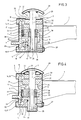
- the opposite end of the arm is free in the case of an application as a support or support arm (FIG. 2) or equipped with a support pad 26 in contact with the support plane in the case of an application in wedge (FIG. 1) thus making it possible to completely relieve the mechanical grip of the base 3 on the support profile 4 during the bearing force of the wheel.
- the pivoting arm 1 moves angularly around the pivot axis 2 which it uses as a bearing by means of the openings of the flanges 20 and 21.
- This axis is made stationary in rotation by the intermediary of any blocking, for example using a screw 27.
- it remains mobile in translation, from top to bottom and vice versa, perpendicular to the arm and to its angular plane of movement as shown by the light located on either side of this screw.
- the pivot axis 2 is provided upwards with a generally mushroom-shaped end piece constituting a bearing surface intended to receive a vertical actuating pressure by the foot.
- This end piece will therefore be called pedal 28 hereinafter.
- the pivot axis 2 is mounted in axial elastic return upwards by a return spring 29 concentric with the axis, housed under the end piece, in the volume delimited between its rear underside and a facing surface 30 of the upper yoke 11 which has a slight cavity 31 at this point delimited by an edge 32 intended to receive the base of the concentric return spring 29.
- pivot axis 2 is formed of two distinct parts: a main part 33 having a circular narrowing shoulder 34 at about half the length, ending in a cylindrical part 35 more small diameter which carries an armament 36 attached at the end and integral with this axis.
- this two-piece structure can be made in one piece depending on the facilities machining.
- the arming piece 36, the concentric return spring 29 of the axis and an arming spring described below form an arming-triggering device 37 of the locking-blocking controlled by the arming spring and arm as we will see it below.
- the technical space located between the circular narrowing shoulder 34 and the top of the part 35 forms a crank pin on which is mounted, by means of a deformable displaceable ring 38, a movable blocking part 39 constituting, with the rear end of the arm and the pivot axis, the locking-unlocking mechanism 9.
- This locking piece 39 is axially movable from bottom to top and vice versa with the pivot axis 2 which carries it.
- the movable blocking part 39 comprises, at its front end, a front wall 40 provided with a support and blocking pad 41 against the internal face 8 of the support profile. It has a rear wall 42, the upper part of which is shaped in a suitable manner to allow, from the angular movement of blocking of the arm, a transverse movement of the part 39 forcing in blocking blocking the shoe 41 against the internal face 8 of the profile. carrier 4.
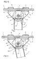
- FIG. 9 A clear distinction is made in FIG. 9 between the symmetrical surfaces in contact which provide two symmetrical locking positions relative to the perpendicular position of the arm of FIG. 8.
- the armament 36 has in a transverse plane a hollow cam 48 formed of a succession of grooves or grooves, for example three grooves 49, 50 and 51 in the cylindrical lateral surface of the armament 36, whose bottom planes are, for example, perpendicular two by two.
- grooves are used for the temporary housing of a latching part or a part thereof, for example an arming spring 54 by its body or its end which takes the form of a rod or of a blade 55.
- the rod or the blade 55 is arranged in line with the grooves or grooves of the cam.
- the rod or blade 55 blocks the ascent of the axis 2 when the latter is pressed in and housed in one or the other of the grooves or grooves. It releases this axis moving upwards when it leaves said groove by its lifting consecutive to the passage from the adjacent rounded corner.
- the spring is of the rod or leaf type made, for example, of tinsel steel, of which, for reasons of simplicity of construction, one of the ends 56 is immobilized in the lower flange of the arm and the other end of which is free through a window 57.
- the domed appearance results from the contact pressure of the adjacent rounded corner between two consecutive grooves, which compresses it over part of its length against its fixed end by a cantilever compression work.
- the spring rod After passing the adjacent corner, comes out of the groove , mechanically releasing the pivot axis in its rise, under the effect of the return spring, with a view to blocking the wedge on its support profile, by an additional angular movement of the arm.
- the arm is in the initial state in the folded position against the straight supporting element leaving the way open for vehicles carried by the loading plane.
- the arm will rotate freely after release of the pedal and engagement of the arming spring 54 in one of the grooves.
- the arm is then pivoted in the proper direction from right to left or from left to right.
- the return spring of the pivot axis automatically brings the latter up with the locking piece 37 which, by the play of mechanical contact between the front plane of thrust 25 of the rear end of the arm and the rear wall bevelled of the blocking piece ensures the thrust thereof towards the internal face 8 of the carrier profile and the correlative immobilization contact of jamming of the lining of its front edge on the carrier profile.
- An additional deflection leads to the blocking position in which the spring has clearly exceeded the cocking position and is vertical to a groove arranged at an angle but sufficiently inclined relative to the spring so that it can receive it without additional angular deviation.
- the additional deflection allows the arm to block by pressing its rear end front on the rear wall of the blocking piece. At the end of blocking it is located above the next groove, ready to be housed therein by the movement of the pivot axis following a depressing action on the pedal ( Figure 8). When this occurs, it sinks into the throat without additional angular movement of the arm.
- the arming and locking positions differ from each other by an angular difference of about 30 °.
- two wedges are arranged converging or diverging in the locking position under each wheel so as to support and block each wheel as load-bearing structures with clamps.
- This arrangement can also be used to stall a vehicle by its only front wheels.
Claims (14)
- Baueinheit zum Festsetzen oder Abstützen eines Kraftfahrzeugs mittels seiner Räder mit einem Schwenkarm (1), der mit seinem hinteren Ende an einer vertikalen Achse (2) schwenkbar gelagert ist, die von einem translatorisch entlang eines Tragprofils (4) verschiebbaren Sockel (3) getragen ist und durch Druckkontakt an diesem Tragprofil (4) mittels eines Blockierstücks (39) festgesetzt werden kann, dadurch gekennzeichnet, daß das an der Schwenkachse (2) schwenkbar gelagerte Ende des Schwenkarms (1) an der Innenraumfläche seines nahe dem Tragprofil (4) liegenden Endstücks eine Aufnahme- und Druckanordnung auf dem Blockierstück (39) aufweist, um durch Zwischenschaltung dieses Blockierstücks (39) einen Druckkontakt auf der Innenseite des Tragprofils (4) unter Wirkung des durch das schwenkbar gelagerte Ende des Arms innerhalb eines festgelegten Winkelbereichs der Ausfederung erzeugten Drucks sowie eine Winkelblockierung des Schwenkarms (1) herzustellen, und daß das Blockierstück (39) unter der Wirkung einer Spann-,Auslöseeeinrichtung (37) der Richtung der Drehachse folgend axial verschiebbar ist zwischen einer oberen Stellung, in der die Winkelbewegung des Arms innerhalb eines festgelegten Winkelbereichs ein gemeinsames Blockieren der Schwenkbewegung des Arms (1) und der Translationsbewegung seines Sockels (3) am Tragprofil (4) erlaubt, und einer unteren Stellung, in der das Blockierstück (39) von der Druckeinwirkung freikommt und den Arm zum Schwenken freigibt, wobei das hintere Ende des Arms und die Schwenkachse (2) mit dem Blockierstück (39) einen Verriegelungs- und Entriegelungsmechanismus (9) bilden.
- Baueinheit nach Anspruch 1, dadurch gekennzeichnet, daß das Blockierstück (39) auf der Schwenkachse (2) angebracht und diese axial beweglich ist.
- Baueinheit zum Festsetzen oder Abstützen nach Anspruch 2, dadurch gekennzeichnet, daß das Blockierstück (39) auf der Drehachse (2) mit einer transversalen Druck-Ausfederung axial festsetzbar ist und an seinem vorderen Ende eine Kontakt- und infolge Flächnandrucks eine Blockierstirnseite in Bezug auf das Tragprofil (4) aufweist.
- Baueinheit zum Festsetzen oder Abstützen nach einem der Ansprüche 2 oder 3, dadurch gekennzeichnet, daß das Blockierstück (39) axial mit der Drehachse (2) verschiebbar ist, die es unter Wirkung der Spann-, Auslöseeinrichtung (37) trägt, die es in Richtung nach unten zurückhält oder es beim Auslösen in elastischer Rückführung nach oben freigibt.
- Baueinheit zum Festsetzen oder Abstützen nach einem der vorangehenden Ansprüche, dadurch gekennzeichnet, daß das hintere Ende des Schwenkarms (1) zwei mechanisch miteinander verbundene Flansche (20, 21) aufweist, die in ihrem Zentrum mit Öffnungen versehen und von der Schwenkachse (2) getragen sind, wobei die zwei Flansche (20, 21) ein Einspannungteil (22) mit einem Querprofil in Form eines liegenden U's bilden, dessen Innenfläche oben entsprechend einer Schulter ausgebildet ist, die durch eine Auslöserampe (24) und eine dieser nach vorne und oben folgende vertikale Druckanschlagfläche (25) über dem Blokkierstück (39) definiert ist, um eine Klemmblockierung zu erreichen, wobei die vertikale Druckanschlagfläche (25) des Schwenkarms (1) eben und senkrecht zur Achse des Schwenkarms ausgebildet ist.
- Baueinheit zum Festsetzen oder Abstützen nach einem der vorangehenden Ansprüche, dadurch gekennzeichnet, daß das Blockierstück (39) eine mit der Schulter des Endteils (22) des Arms zusammenwirkende Rückwand aufweist, um diesen durch Pressen gegen die benachbarte Fläche des Tragprofils (4) zu blockieren durch Zusammenwirken einerseits der Spann-, Auslöseeinrichtung (37), die die Achse in Spannlage bringt, andererseits des Verriegelungs- und Entriegelungsmechanismus (9), der durch die Winkel-Schenkbewegung des Arms in einem festgelegten Winkelbereich gesteuert wird.
- Baueinheit zum Festsetzen oder Abstützen nach einem der Ansprüche 5 oder 6, dadurch gekennzeichnet, daß die Schwenkachse (2) von einem Hauptteil (33) gebildet ist, welches ungefähr auf halber Länge eine kreisförmige Schultereinschnürung (34) aufweist, um in ein zylindrisches Teil (35) geringeren Durchmessers überzugehen, welches ein am Ende der Achse aufgesetztes und mit dieser verbundenes Spannteil (36) trägt, wobei der technische Zwischenraum zwischen der Schulter (34) und dem oberen Bereich des Teils (35) einen Zapfen bildet, auf dem unter Zwischenschaltung eines beweglichen verformbaren Rings (38) das bewegliche Blockierstück (39) angeordnet ist.
- Baueinheit zum Festsetzen oder Abstützen nach einem der Ansprüche 5,6 oder 7, dadurch gekennzeichnet, daß die Rückwand des Blockierstücks (39) eine Druckfläche aufweist, die von zwei durch eine Abflachung (46) getrennten Abschrägungen (44) gebildet ist.
- Baueinheit zum Festsetzen oder Abstützen nach den vorangehenden Ansprüchen in ihrer Gesamtheit, dadurch gekennzeichnet, daß die Schwenkachse (2) in elastischer Rückstellung nach oben in der Verriegelung des Arms angeordnet ist.
- Baueinheit zum Festsetzen oder Abstützen nach Anspruch 9, dadurch gekennzeichnet, daß die Spann-, Auslöseeinrichtung (37) ein Teil der Schwenkachse ist, welche ein selektives Halten derselben in der unteren Schwenkposition in dem Schwenkwinkelbereich ermöglicht.
- Baueinheit zum Festsetzen und Abstützen nach Anspruch 10, dadurch gekennzeichnet, daß die Spann-, Auslöseeinrichtung (37) eine vertiefte Kurve (48) ist, in deren Vertiefung wahlweise eine Klinke oder ein Teil dieser Klinke einsitzt.
- Baueinheit zum Festsetzen oder Abstützen nach Anspruch 11, dadurch gekennzeichnet, daß die Klinke eine Spannfeder (54) mit Blatt oder Stift (55) und die vertiefte Kurve (48) ein Teil ist, welches in einer transversalen Ebene mit mehreren Vertiefungen oder Nuten (49, 50, 51) versehen ist, die durch die Vertiefungen an den Seitenflächen verbindende Kanten (52, 53) getrennt sind, um die Aufnahme und die Freigabe des Stiftes während der Drehung der Schwenkachse sicherzustellen.
- Baueinheit zum Festsetzen oder Abstützen nach Anspruch 12, dadurch gekennzeichnet, daß die mit Vertiefungen versehene Kurve (48) die Schwenkachse (2) ist.
- Baueinheit zum Festsetzen oder Abstützen nach Anspruch 1, dadurch gekennzeichnet, daß die Schwenkachse (2) an ihrem oberen Ende von einem pilzförmigen Pedal (28) zum manuellen Rückstellen der Einrichtung begrenzt ist.
Applications Claiming Priority (2)
| Application Number | Priority Date | Filing Date | Title |
|---|---|---|---|
| FR9000309 | 1990-01-09 | ||
| FR9000309A FR2656858B1 (fr) | 1990-01-09 | 1990-01-09 | Structure unitaire deplacable de calage ou de soutien d'un vehicule routier par ses roues. |
Publications (2)
| Publication Number | Publication Date |
|---|---|
| EP0437413A1 EP0437413A1 (de) | 1991-07-17 |
| EP0437413B1 true EP0437413B1 (de) | 1994-07-13 |
Family
ID=9392696
Family Applications (1)
| Application Number | Title | Priority Date | Filing Date |
|---|---|---|---|
| EP91440001A Expired - Lifetime EP0437413B1 (de) | 1990-01-09 | 1991-01-09 | Verschiebbare einheitliche Struktur zur Befestigung oder zum Unterstützen von Fahrzeugrädern |
Country Status (5)
| Country | Link |
|---|---|
| EP (1) | EP0437413B1 (de) |
| AT (1) | ATE108377T1 (de) |
| DE (1) | DE69102773T2 (de) |
| ES (1) | ES2056610T3 (de) |
| FR (1) | FR2656858B1 (de) |
Families Citing this family (7)
| Publication number | Priority date | Publication date | Assignee | Title |
|---|---|---|---|---|
| DE4126005A1 (de) * | 1991-08-06 | 1993-02-11 | Graaff Gmbh | Radvorleger fuer autotransportfahrzeuge |
| US5415505A (en) * | 1991-10-30 | 1995-05-16 | G & G Intellectual Properties, Inc. | Vehicle-carrying frame |
| FR2730462A1 (fr) * | 1995-02-10 | 1996-08-14 | Pierre Neuville Ets | Cale pour le transport de vehicules automobiles |
| CA2208465C (en) | 1996-12-02 | 2005-05-10 | James A. Ditch | Tie down for wheelchairs |
| US6113325A (en) | 1997-09-29 | 2000-09-05 | Craft; Richard D. | Wheelchair restraint system for a transportation vehicle |
| US7455490B1 (en) | 2004-07-21 | 2008-11-25 | Gregory F Goosen | Wheelchair holding device |
| CN107394699A (zh) * | 2017-09-06 | 2017-11-24 | 荣成中元电器有限公司 | 一种线束式理线排线器 |
Family Cites Families (4)
| Publication number | Priority date | Publication date | Assignee | Title |
|---|---|---|---|---|
| FR2419198A2 (fr) * | 1976-12-29 | 1979-10-05 | Niesky Waggonbau Veb | Cale de blocage de roue pour wagons de transport de voitures automobiles |
| FR2606716B1 (fr) * | 1986-11-18 | 1989-02-03 | Lohr Sa | Bras unitaire porteur pour le soutien d'un vehicule par ses roues |
| FR2609671B1 (fr) * | 1987-01-16 | 1989-05-05 | Lohr Sa | Element escamotable de soutien d'un vehicule par ses roues utilisable par paires notamment sur vehicule porte-voitures |
| FR2612853B1 (fr) * | 1987-03-26 | 1991-05-17 | Lohr Sa | Cale pivotante autoverrouillable pour l'immobilisation d'un vehicule automobile sur un plan de chargement |
-
1990
- 1990-01-09 FR FR9000309A patent/FR2656858B1/fr not_active Expired - Fee Related
-
1991
- 1991-01-09 EP EP91440001A patent/EP0437413B1/de not_active Expired - Lifetime
- 1991-01-09 DE DE69102773T patent/DE69102773T2/de not_active Expired - Fee Related
- 1991-01-09 AT AT91440001T patent/ATE108377T1/de not_active IP Right Cessation
- 1991-01-09 ES ES91440001T patent/ES2056610T3/es not_active Expired - Lifetime
Also Published As
| Publication number | Publication date |
|---|---|
| DE69102773D1 (de) | 1994-08-18 |
| FR2656858B1 (fr) | 1992-05-15 |
| EP0437413A1 (de) | 1991-07-17 |
| DE69102773T2 (de) | 1995-02-23 |
| ATE108377T1 (de) | 1994-07-15 |
| FR2656858A1 (fr) | 1991-07-12 |
| ES2056610T3 (es) | 1994-10-01 |
Similar Documents
| Publication | Publication Date | Title |
|---|---|---|
| EP2043824B1 (de) | Vorrichtung zur schnellen montage von werkzeugen auf einem träger | |
| EP0277896B1 (de) | Schwenkbare Stützvorrichtung für die Räder eines Fahrzeuges, paarweise verwendbar, insbesondere auf Autotransportfahrzeugen | |
| FR2658108A1 (fr) | Dispositif de serrage a action rapide. | |
| EP2659149B1 (de) | Vorrichtung zum gegenseitigen verriegeln zweier gleitbare montierbarer rohre | |
| EP2307237B1 (de) | Entlang einem teilabschnitt verschiebbarer unterlegteil, der durch schwenken gegen diesen teilabschnitt umgeklappt werden kann, für jeden reifen eines von einer transporteinheit beförderten strassenfahrzeugs | |
| FR2794422A3 (fr) | Frein a disque avant pour bicyclette | |
| FR2715119A1 (fr) | Bras perfectionné d'autoguidage d'un véhicule routier le long d'un rail directeur. | |
| EP0768469A1 (de) | Schnellspannbefestigungsvorrichtung auf einem Gewindeschaft zum Drehantrieb | |
| EP1626893B1 (de) | Vorrichtung mit einem schnellklemmmechanismus zur befestigung eines fahrradrades an einem rahmen mit einem überhang | |
| FR2917471A1 (fr) | Attache de support et de fixation d'une structure sur une paroi, structure associee, et ensemble de structure correspondant | |
| EP0437413B1 (de) | Verschiebbare einheitliche Struktur zur Befestigung oder zum Unterstützen von Fahrzeugrädern | |
| FR2777049A1 (fr) | Systeme d'arrimage modulable a commande par cames | |
| EP3203000A1 (de) | Schloss eines öffnungsflügels mit einem elastisch einklinkbaren sockel | |
| EP2930130B1 (de) | Keilvorrichtung als wegfahrsperre für fahrzeug | |
| FR2623431A1 (fr) | Mandrin de serrage pour machine-outil | |
| EP0734338B1 (de) | Einrichtung zur befestigung eines rades eines motorrades am ständer und leistungsprüfstand dafür | |
| FR2497184A1 (fr) | Engin de levage | |
| FR2966490A1 (fr) | Verrou a crochet muni d'un ressort perfectionne | |
| CH629106A5 (fr) | Fixation de securite pour ski. | |
| EP0083881B1 (de) | Schwimmsattel-Scheibenbremse | |
| FR2759049A1 (fr) | Chariot d'achat a pivot deverrouillable | |
| FR2730264A1 (fr) | Ensemble de plaques et poignees de porte comportant un dispositif de rappel en position de la poignee | |
| FR2809976A1 (fr) | Porte-outil pour le montage d'un outil sur une presse plieuse | |
| EP0330556B1 (de) | Drehscheibe zum Ausstellen eines Kraftfahrzeuges | |
| FR2801527A1 (fr) | Pince de pose d'un dispositif d'ancrage tel qu'une cheville metallique a expansion ou analogue |
Legal Events
| Date | Code | Title | Description |
|---|---|---|---|
| PUAI | Public reference made under article 153(3) epc to a published international application that has entered the european phase |
Free format text: ORIGINAL CODE: 0009012 |
|
| AK | Designated contracting states |
Kind code of ref document: A1 Designated state(s): AT BE CH DE ES GB IT LI LU NL |
|
| 17P | Request for examination filed |
Effective date: 19911004 |
|
| 17Q | First examination report despatched |
Effective date: 19930114 |
|
| GRAA | (expected) grant |
Free format text: ORIGINAL CODE: 0009210 |
|
| AK | Designated contracting states |
Kind code of ref document: B1 Designated state(s): AT BE CH DE ES GB IT LI LU NL |
|
| REF | Corresponds to: |
Ref document number: 108377 Country of ref document: AT Date of ref document: 19940715 Kind code of ref document: T |
|
| REF | Corresponds to: |
Ref document number: 69102773 Country of ref document: DE Date of ref document: 19940818 |
|
| REG | Reference to a national code |
Ref country code: ES Ref legal event code: FG2A Ref document number: 2056610 Country of ref document: ES Kind code of ref document: T3 |
|
| ITF | It: translation for a ep patent filed |
Owner name: MARIETTI E GISLON S.R.L. |
|
| GBT | Gb: translation of ep patent filed (gb section 77(6)(a)/1977) |
Effective date: 19941017 |
|
| PG25 | Lapsed in a contracting state [announced via postgrant information from national office to epo] |
Ref country code: LU Free format text: LAPSE BECAUSE OF NON-PAYMENT OF DUE FEES Effective date: 19950131 |
|
| PLBE | No opposition filed within time limit |
Free format text: ORIGINAL CODE: 0009261 |
|
| STAA | Information on the status of an ep patent application or granted ep patent |
Free format text: STATUS: NO OPPOSITION FILED WITHIN TIME LIMIT |
|
| 26N | No opposition filed | ||
| PGFP | Annual fee paid to national office [announced via postgrant information from national office to epo] |
Ref country code: CH Payment date: 19960119 Year of fee payment: 6 |
|
| PGFP | Annual fee paid to national office [announced via postgrant information from national office to epo] |
Ref country code: BE Payment date: 19960122 Year of fee payment: 6 |
|
| PGFP | Annual fee paid to national office [announced via postgrant information from national office to epo] |
Ref country code: NL Payment date: 19960131 Year of fee payment: 6 |
|
| PG25 | Lapsed in a contracting state [announced via postgrant information from national office to epo] |
Ref country code: LI Effective date: 19970131 Ref country code: CH Effective date: 19970131 Ref country code: BE Effective date: 19970131 |
|
| BERE | Be: lapsed |
Owner name: S.A. LOHR INDUSTRIE Effective date: 19970131 |
|
| PG25 | Lapsed in a contracting state [announced via postgrant information from national office to epo] |
Ref country code: NL Effective date: 19970801 |
|
| GBPC | Gb: european patent ceased through non-payment of renewal fee |
Effective date: 19970109 |
|
| REG | Reference to a national code |
Ref country code: CH Ref legal event code: PL |
|
| NLV4 | Nl: lapsed or anulled due to non-payment of the annual fee |
Effective date: 19970801 |
|
| REG | Reference to a national code |
Ref country code: GB Ref legal event code: 728V |
|
| REG | Reference to a national code |
Ref country code: GB Ref legal event code: 728Y |
|
| REG | Reference to a national code |
Ref country code: GB Ref legal event code: IF02 |
|
| PGFP | Annual fee paid to national office [announced via postgrant information from national office to epo] |
Ref country code: GB Payment date: 20021231 Year of fee payment: 13 |
|
| PGFP | Annual fee paid to national office [announced via postgrant information from national office to epo] |
Ref country code: ES Payment date: 20030115 Year of fee payment: 13 |
|
| PGFP | Annual fee paid to national office [announced via postgrant information from national office to epo] |
Ref country code: DE Payment date: 20030123 Year of fee payment: 13 |
|
| PGFP | Annual fee paid to national office [announced via postgrant information from national office to epo] |
Ref country code: AT Payment date: 20030128 Year of fee payment: 13 |
|
| PG25 | Lapsed in a contracting state [announced via postgrant information from national office to epo] |
Ref country code: GB Free format text: LAPSE BECAUSE OF NON-PAYMENT OF DUE FEES Effective date: 20040109 Ref country code: AT Free format text: LAPSE BECAUSE OF NON-PAYMENT OF DUE FEES Effective date: 20040109 |
|
| PG25 | Lapsed in a contracting state [announced via postgrant information from national office to epo] |
Ref country code: ES Free format text: LAPSE BECAUSE OF NON-PAYMENT OF DUE FEES Effective date: 20040110 |
|
| PG25 | Lapsed in a contracting state [announced via postgrant information from national office to epo] |
Ref country code: DE Free format text: LAPSE BECAUSE OF NON-PAYMENT OF DUE FEES Effective date: 20040803 |
|
| GBPC | Gb: european patent ceased through non-payment of renewal fee |
Effective date: 20040109 |
|
| PG25 | Lapsed in a contracting state [announced via postgrant information from national office to epo] |
Ref country code: IT Free format text: LAPSE BECAUSE OF NON-PAYMENT OF DUE FEES;WARNING: LAPSES OF ITALIAN PATENTS WITH EFFECTIVE DATE BEFORE 2007 MAY HAVE OCCURRED AT ANY TIME BEFORE 2007. THE CORRECT EFFECTIVE DATE MAY BE DIFFERENT FROM THE ONE RECORDED. Effective date: 20050109 |
|
| REG | Reference to a national code |
Ref country code: ES Ref legal event code: FD2A Effective date: 20040110 |