EP0064146B1 - Système d'injection pour injecter deux combustibles par une seule buse d'injection - Google Patents
Système d'injection pour injecter deux combustibles par une seule buse d'injection Download PDFInfo
- Publication number
- EP0064146B1 EP0064146B1 EP82102059A EP82102059A EP0064146B1 EP 0064146 B1 EP0064146 B1 EP 0064146B1 EP 82102059 A EP82102059 A EP 82102059A EP 82102059 A EP82102059 A EP 82102059A EP 0064146 B1 EP0064146 B1 EP 0064146B1
- Authority
- EP
- European Patent Office
- Prior art keywords
- fuel
- injection
- nozzle needle
- pressure
- main
- Prior art date
- Legal status (The legal status is an assumption and is not a legal conclusion. Google has not performed a legal analysis and makes no representation as to the accuracy of the status listed.)
- Expired
Links
- 239000000446 fuel Substances 0.000 title claims abstract description 145
- 238000002347 injection Methods 0.000 title claims abstract description 64
- 239000007924 injection Substances 0.000 title claims abstract description 64
- 238000002485 combustion reaction Methods 0.000 abstract description 9
- 238000011144 upstream manufacturing Methods 0.000 description 8
- 238000000034 method Methods 0.000 description 6
- 230000006835 compression Effects 0.000 description 4
- 238000007906 compression Methods 0.000 description 4
- 238000006073 displacement reaction Methods 0.000 description 3
- 239000007921 spray Substances 0.000 description 2
- 238000010276 construction Methods 0.000 description 1
- 230000000694 effects Effects 0.000 description 1
- 230000000149 penetrating effect Effects 0.000 description 1
- 108090000623 proteins and genes Proteins 0.000 description 1
Images
Classifications
-
- F—MECHANICAL ENGINEERING; LIGHTING; HEATING; WEAPONS; BLASTING
- F02—COMBUSTION ENGINES; HOT-GAS OR COMBUSTION-PRODUCT ENGINE PLANTS
- F02M—SUPPLYING COMBUSTION ENGINES IN GENERAL WITH COMBUSTIBLE MIXTURES OR CONSTITUENTS THEREOF
- F02M43/00—Fuel-injection apparatus operating simultaneously on two or more fuels, or on a liquid fuel and another liquid, e.g. the other liquid being an anti-knock additive
- F02M43/04—Injectors peculiar thereto
Definitions
- the invention relates to an injection system for injecting two fuels through a single injection valve, in which the two fuels are fed separately from separate injection pumps and only meet in the area of the tip of a nozzle needle of the injection valve, a main fuel line through a pressure relief valve, in particular on the injection pump can be relieved of pressure for the main fuel, a non-return valve being assigned to a pilot fuel line in the immediate vicinity of the outlet opening of the pilot fuel line and a spring-loaded piston being provided within the injection valve, which piston is in operative connection with the main fuel line.
- an injection valve for injecting ignition fuel on the one hand and ignition-resistant main fuel on the other hand for diesel engines is known.
- This injection valve has a separate feed for the main fuel and the pilot fuel to the nozzle needle seat.
- the pilot fuel and the main fuel are delivered by two separate pumps, with the main fuel pump being a high-pressure injection pump and the pilot fuel pump being a commercially available delivery pump which operates at a delivery pressure of 20-50 bar.
- the pilot fuel is deposited on one side and the main fuel on the other side of the nozzle needle above the seat thereof.
- a spring-loaded pre-injection piston with differential pistons is provided in the pilot fuel channel, which is connected on its spring-loaded side to the main fuel channel via a branch channel.
- the pilot fuel is supplied on the side opposite the spring-loaded piston side, so that the piston must be displaced by the pilot fuel against the pressure of the spring so that the necessary quantity of pilot fuel can be supplied.
- the main fuel If the main fuel is then only slightly pressurized, it can act via the branch channel on the spring-loaded side of the pre-injection piston and, due to the differential piston, increases the pressure in such a way that the nozzle needle is raised so that the pilot fuel is injected into the combustion chamber. Then the pressure of the pilot fuel collapses, the nozzle needle closes again and only after a sufficient pressure has built up in the main fuel does it open again and allow the main fuel to enter the combustion chamber.
- pilot fuel pre-charges to the main fuel without the need for a differential piston.
- the main fuel line is relieved of pressure on the injection pump by a pressure relief valve.
- the pilot fuel compresses the pressure-relieved main fuel inside the nozzle and in the main fuel line and thereby displaces the main fuel at the nozzle needle tip.
- the pilot fuel upstream of the nozzle needle tip is injected first in time.
- a check valve arranged in the vicinity of the outlet opening of the pilot fuel line prevents the pilot fuel from flowing back. If the amount of pilot fuel is to be metered exactly, further separate devices, such as solenoid valves and metering pistons, are provided.
- pilot fuel injection pump must provide the relatively high pressure of 20-50 bar. Injection pumps of this type require a relatively large amount of construction work and are therefore expensive in comparison with simple feed pumps. In a disadvantageous manner, additional devices, such as solenoid valves, are still required for the exact metering of the pilot fuel.
- an injection valve for injecting ignition and main fuel is also known.
- both fuel lines are equipped with check valves.
- a spring-loaded displacement piston is arranged in a branch line of the main fuel line and, depending on its position, provides relief space for the main fuel.
- Both fuel lines open near the nozzle needle tip. If pilot fuel is to be upstream of the main fuel, the check valve of the main fuel line is closed and the main fuel is pressed into the piston chamber of the displacer piston by the pressure of the pilot fuel against the spring force of the displacer.
- the pilot fuel thus creates space in that it presses the main fuel against the spring force virtually in front of it into the relief space created by the displacement piston.
- DE-A-2 908 375 proposes an injection valve for injecting two fuels gene, in which two high-pressure injection pumps deliver the two fuels, i.e. both the main fuel and the pilot fuel, separately. Only in the vicinity of the nozzle needle tip do the two fuel channels meet, separated by a check valve each located there. Both injection pumps work at very high pressure, ie around 250 bar. Thus, here too, the pilot fuel injection pump is disadvantageously designed as an expensive high-pressure injection pump.
- an injection pump which provides the high pressure necessary for injection for a fuel.
- a pressure relief valve is provided on the outlet line of the injection pump in this injection pump.
- a defined relief volume is made available by the stroke of a piston. This relief volume allows the fuel line to be relieved of pressure after the delivery stroke has been completed.
- the object of the present invention is therefore to propose an injection system of the type mentioned at the outset, with which a sufficient quantity of pilot fuel is surely injected into the combustion chamber ahead of the main fuel.
- the pilot fuel is to be upstream of the main fuel at the tip of the nozzle needle using a low-pressure low-pressure feed pump.
- the main fuel acts directly on the pilot fuel.
- the pressure of the main fuel raises the nozzle needle and first injects the pilot fuel.
- Any differential pistons can advantageously be omitted entirely.
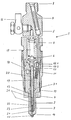
- the single figure shows a cross section through an injection nozzle according to the invention.
- the injection nozzle 1 consists, in a manner known per se, of the nozzle body 2, in which the nozzle needle 3 is arranged centrally and is held in the closed position by the force of the compression spring 6.
- the nozzle body 2 is fastened to the nozzle holder 5 by a union nut 4.
- the main fuel is fed into the nozzle holder 5 at 7. It passes through a rod filter 8 into an inlet bore 9, which can be closed by a piston 10, which is loaded by a spring 11.
- the piston 10 and the spring 11 form a relief valve.
- the piston 10 has a blind bore 10.1 which is equipped with drain openings 10.2 which are closed in the position shown.
- the distance of the drain openings 10.2 from the seat of the piston 10 is a measure of the size of the relief volume. The greater this distance, the greater the relief volume.
- the main fuel After passing through the piston 10, the main fuel reaches the pressure chamber 12, which is arranged concentrically around the nozzle needle 3.
- the nozzle needle 3 has a pressure shoulder 3.1 within the pressure chamber, so that it can be raised against the force of the compression spring at a corresponding pressure of the main fuel.
- An annular channel 13 runs from the pressure chamber 12 to the nozzle needle seat surface. This Ring channel is closed by the nozzle needle in the closed state. In the open state of the nozzle needle, the annular channel 13 ′ merges into an intermediate bore 14, from which one or more spray holes 15 branch off.
- the pilot fuel is preferably supplied according to the invention through the leakage system provided in conventional injectors.
- the pilot fuel passes through its connecting line 16 and bores in the nozzle holder to the compression spring chamber 17 and from there to the nozzle needle.
- the nozzle needle has a blind hole 18 in which a cylindrical insert 19 with a flattened side wall is inserted. As a result, a gap 20 is formed between the flattened side wall and the nozzle needle inner wall.
- the device according to the invention works as follows.
- the injection valve 1 is in the position shown, i. H. the nozzle needle 3 is closed and the piston 10 is in its position shown. He can take this because a pressure relief valve is provided in the main fuel system, so that the pressure in the inlet bore 9 drops after the end of the injection process, so that the spring 11 can move the piston 10 into the position shown.
- the pilot fuel Since the pilot fuel is to be injected first with every injection process, it must also be supplied first. For this purpose, it is supplied by a constant delivery pump with a pressure of 3 to 4 bar via the connecting line 16, the pressure spring chamber 17 into the gap 20 and from there via the central bore 21 to the check valve.
- the spring 23 of the check valve is set such that the check valve opens at a pressure of 2 bar. As a result, the ignition fuel flows into the annular channel 13 via the outlet openings 24.
- the main fuel remaining in the annular channel 13 from the last injection process is also depressurized, since the closing movement of the piston 10 and the nozzle needle seat results in the volume existing between the piston 10 and the nozzle needle seat due to the closing movement of the piston 10, e.g. B. was increased by 10 or 15 mm 3 . As a result, the pilot fuel easily gets into the ring channel and can accumulate around the nozzle needle tip.
- the main fuel is then supplied under pressure.
- the force of the spring 11 of the relief valve is dimensioned such that the main fuel can move the piston 10 so that the main fuel can flow via the discharge openings 10.2 to the pressure chamber 12 and from there into the annular channel 13.
- Due to the pressure of the main fuel the nozzle needle is raised over the pressure shoulder 3.1.
- the pilot fuel upstream of the nozzle needle seat can enter the combustion chamber via the intermediate bore 14 and the spray holes 15, followed by the main fuel.
- both the nozzle needle 3 and the piston 10 close again.
- the relief volume is thus again formed in the main fuel channel between the piston 10 and the nozzle needle seat surface, so that the pilot fuel can be supplied.
- the check valve in the pilot fuel line Due to the check valve in the pilot fuel line, the main fuel is prevented from penetrating into the pilot fuel line during the injection process, so that the main fuel only has to be pushed out again when pilot fuel is supplied. Since this would then fill the relief volume created in the ring channel 13, too little pilot fuel could be stored upstream. For this reason, the check valve is also arranged as close as possible to the outlet openings 24 and has such a low mass that it can react without delay.
Landscapes
- Engineering & Computer Science (AREA)
- Chemical & Material Sciences (AREA)
- Combustion & Propulsion (AREA)
- Mechanical Engineering (AREA)
- General Engineering & Computer Science (AREA)
- Fuel-Injection Apparatus (AREA)
- Feeding, Discharge, Calcimining, Fusing, And Gas-Generation Devices (AREA)
Claims (4)
Priority Applications (1)
| Application Number | Priority Date | Filing Date | Title |
|---|---|---|---|
| AT82102059T ATE13931T1 (de) | 1981-05-06 | 1982-03-13 | Einspritzsystem zum einspritzen zweier brennstoffe durch eine einspritzduese. |
Applications Claiming Priority (2)
| Application Number | Priority Date | Filing Date | Title |
|---|---|---|---|
| DE19813117796 DE3117796A1 (de) | 1981-05-06 | 1981-05-06 | Einspritzsystem zum einspritzen zweier brennstoffe durch eine einspritzduese |
| DE3117796 | 1981-05-06 |
Publications (2)
| Publication Number | Publication Date |
|---|---|
| EP0064146A1 EP0064146A1 (fr) | 1982-11-10 |
| EP0064146B1 true EP0064146B1 (fr) | 1985-06-19 |
Family
ID=6131527
Family Applications (1)
| Application Number | Title | Priority Date | Filing Date |
|---|---|---|---|
| EP82102059A Expired EP0064146B1 (fr) | 1981-05-06 | 1982-03-13 | Système d'injection pour injecter deux combustibles par une seule buse d'injection |
Country Status (4)
| Country | Link |
|---|---|
| US (1) | US4465237A (fr) |
| EP (1) | EP0064146B1 (fr) |
| AT (1) | ATE13931T1 (fr) |
| DE (2) | DE3117796A1 (fr) |
Families Citing this family (14)
| Publication number | Priority date | Publication date | Assignee | Title |
|---|---|---|---|---|
| GB2126650B (en) * | 1982-08-31 | 1988-02-10 | George Stan Baranescu | I c engine injection system providing a stratified charge of two fuels |
| DE3237932A1 (de) * | 1982-10-13 | 1984-04-19 | Robert Bosch Gmbh, 7000 Stuttgart | Kraftstoff-einspritzduese fuer brennkraftmaschinen |
| JP2526856B2 (ja) * | 1984-12-19 | 1996-08-21 | トヨタ自動車株式会社 | 二種の燃料を順次に噴射可能な燃料噴射装置 |
| DE3770275D1 (de) * | 1986-07-30 | 1991-06-27 | Elsbett L | Einspritzvorrichtung zum einbringen von kraftstoffen in den brennraum einer brennkraftmaschine. |
| JP2538908B2 (ja) * | 1987-03-15 | 1996-10-02 | 三菱重工業株式会社 | 2種燃料エンジンの噴射システム |
| US5311902A (en) * | 1991-07-02 | 1994-05-17 | Overfield Norbert W | Reciprocating compressor valve |
| EP0694123A1 (fr) * | 1994-02-11 | 1996-01-31 | Mtu Motoren- Und Turbinen-Union Friedrichshafen Gmbh | Systeme d'injection |
| US5899385A (en) * | 1995-07-21 | 1999-05-04 | Robert Bosch Gmbh | Fuel injection valve for internal combustion engines |
| DE602006008377D1 (de) * | 2005-04-28 | 2009-09-24 | Delphi Tech Inc | Einspritzdüse |
| DE602007011961D1 (de) | 2006-10-13 | 2011-02-24 | Parker Hannifin Corp | Dreiweg-tellerventil |
| US9068539B2 (en) | 2012-08-03 | 2015-06-30 | Caterpillar Inc. | Dual check fuel injector and fuel system using same |
| GB201309122D0 (en) | 2013-05-21 | 2013-07-03 | Delphi Tech Holding Sarl | Fuel Injector |
| GB2543826B (en) * | 2015-10-30 | 2019-07-24 | Caterpillar Inc | A fuel injector, a fuel injector assembly and an associated method |
| DE102015015518B4 (de) | 2015-11-26 | 2023-04-27 | Hermann GOLLE | Kraftstoff/Luft-Einspritzsystem für Verbrennungsmotoren |
Citations (2)
| Publication number | Priority date | Publication date | Assignee | Title |
|---|---|---|---|---|
| CH305822A (de) * | 1950-11-17 | 1955-03-15 | Nat Res Dev | Brennstoffeinspritzeinrichtung mit einer Einspritzdüse und einer Kolbenpumpe. |
| DE2547783A1 (de) * | 1974-12-19 | 1976-06-24 | Friedmann & Maier Ag | Brennstoffeinspritzpumpe |
Family Cites Families (13)
| Publication number | Priority date | Publication date | Assignee | Title |
|---|---|---|---|---|
| FR484774A (fr) * | 1916-03-14 | 1917-11-06 | Edward Gardner | Perfectionnements aux injecteurs de combustibles pour moteurs à combustion interne |
| GB120609A (en) * | 1917-11-10 | 1918-11-11 | Kenneth Irwin Crossley | Improvements in Oil Fuel Injection Devices for Internal Combustion Engines. |
| DE479273C (de) * | 1925-11-03 | 1929-07-13 | Motorenfabrik Deutz Akt Ges | Einspritzvorrichtung fuer Dieselmotoren mit Zuendoelvorlagerung |
| DE568366C (de) * | 1931-12-09 | 1933-01-18 | Fried Krupp Germaniawerft Akt | Brennstoffnadelventil fuer Einspritzbrennkraftmaschinen |
| DE577810C (de) * | 1932-02-13 | 1933-06-06 | Motorenfabrik Herford Ges M B | Einspritzvorrichtung fuer zwei verschiedene Brennstoffe |
| CH172170A (de) * | 1933-12-22 | 1934-09-30 | Sulzer Ag | Brennstoffpumpe für mit Zünd- und Treibbrennstoff arbeitende Brennkraftmaschinen. |
| DE849325C (de) * | 1940-09-19 | 1952-09-15 | Bosch Gmbh Robert | Einspritzventil fuer Brennkraftmaschinen |
| CH234210A (de) * | 1943-05-29 | 1944-09-15 | Sulzer Ag | Verfahren und Einrichtung zum Einspritzen unter Druck von zündträgem Brennstoff. |
| US2602703A (en) * | 1947-09-22 | 1952-07-08 | Atlas Diesel Ab | Fuel injection valve |
| DE969853C (de) * | 1952-12-25 | 1958-07-24 | Maschf Augsburg Nuernberg Ag | Einrichtung zur Verwendung verschiedener Brennstoffarten und -mengen bei Einspritzduesen von Brennkraftmaschinen |
| GB1357887A (en) * | 1970-11-05 | 1974-06-26 | Cav Ltd | Fuel injection system for an internal combustion engine |
| DE2908375A1 (de) * | 1979-03-03 | 1980-09-11 | Klaus Dipl Ing Starke | Dieselmotorisches verfahren mit einer vorrichtung zum betrieb mit zwei fluessigen kraftstoffen unter verwendung zweier einspritzpumpensysteme und einer kraftstoffduese |
| DE2924128A1 (de) * | 1979-06-15 | 1980-12-18 | Motoren Werke Mannheim Ag | Einrichtung zur einspritzung von zuendkraftstoff einerseits und zuendunwilligem hauptkraftstoff andererseits fuer dieselmotoren |
-
1981
- 1981-05-06 DE DE19813117796 patent/DE3117796A1/de not_active Withdrawn
-
1982
- 1982-03-13 DE DE8282102059T patent/DE3264208D1/de not_active Expired
- 1982-03-13 AT AT82102059T patent/ATE13931T1/de not_active IP Right Cessation
- 1982-03-13 EP EP82102059A patent/EP0064146B1/fr not_active Expired
- 1982-05-04 US US06/374,911 patent/US4465237A/en not_active Expired - Fee Related
Patent Citations (2)
| Publication number | Priority date | Publication date | Assignee | Title |
|---|---|---|---|---|
| CH305822A (de) * | 1950-11-17 | 1955-03-15 | Nat Res Dev | Brennstoffeinspritzeinrichtung mit einer Einspritzdüse und einer Kolbenpumpe. |
| DE2547783A1 (de) * | 1974-12-19 | 1976-06-24 | Friedmann & Maier Ag | Brennstoffeinspritzpumpe |
Also Published As
| Publication number | Publication date |
|---|---|
| US4465237A (en) | 1984-08-14 |
| DE3117796A1 (de) | 1982-11-25 |
| ATE13931T1 (de) | 1985-07-15 |
| EP0064146A1 (fr) | 1982-11-10 |
| DE3264208D1 (en) | 1985-07-25 |
Similar Documents
| Publication | Publication Date | Title |
|---|---|---|
| DE2954686C2 (fr) | ||
| EP0064146B1 (fr) | Système d'injection pour injecter deux combustibles par une seule buse d'injection | |
| DE60125098T2 (de) | Kraftstoffeinspritzventil | |
| EP0694123A1 (fr) | Systeme d'injection | |
| DE3629751C2 (de) | Voreinspritzvorrichtung für Brennkraftmaschinen | |
| WO2004003376A1 (fr) | Injecteur de carburant a multiplicateur de pression a reduction de pression rapide lors de l'injection | |
| DE4421714A1 (de) | Kraftstoffeinspritzsystem | |
| DE10229415A1 (de) | Einrichtung zur Nadelhubdämpfung an druckgesteuerten Kraftstoffinjektoren | |
| EP0432402B1 (fr) | Dispositif d'injection pour moteur à combustion interne à auto-allumage | |
| EP2410168A1 (fr) | Distributeur de fluide et procédé de préparation d'un fluide de travail à l'aide d'un distributeur de fluide | |
| EP1045975B1 (fr) | Unite servant a commander l'etablissement de la pression dans une unite de pompage | |
| DE3401658C2 (fr) | ||
| DE19802828A1 (de) | Hydraulisch betätigte Einspritzvorrichtung mit nadelventilbetätigtem Überlaufdurchlaß | |
| CH671809A5 (fr) | ||
| EP0610585B1 (fr) | Dispositif d'injection de combustible à pré-injection et injection principale | |
| DE1751080B1 (de) | Kraftstoffeinspritzduese fuer Dieselmotoren | |
| DE10023960A1 (de) | Kraftstoffeinspritzvorrichtung für eine Brennkraftmaschine | |
| DE3009750C2 (de) | Brennstoffeinspritzvorrichtung für Brennkraftmaschinen | |
| EP0610584B1 (fr) | Dispositif d'injection de combustible à pré-injection et injection principale de combustibles différents par un injecteur mono-aiguille | |
| DE4425339C2 (de) | Einspritzsystem | |
| DE102008000082B4 (de) | Einspritzeinrichtung | |
| EP1483499A1 (fr) | Systeme pour moduler en pression le comportement d'injection | |
| DE19746490A1 (de) | Kraftstoffeinspritzanlage für eine Brennkraftmaschine | |
| AT512439A1 (de) | Vorrichtung zum einspritzen von kraftstoff in den brennraum einer brennkraftmaschine | |
| DE3700359C2 (de) | Kraftstoffeinspritzeinrichtung für Brennkraftmaschinen, insbesondere Pumpedüse |
Legal Events
| Date | Code | Title | Description |
|---|---|---|---|
| PUAI | Public reference made under article 153(3) epc to a published international application that has entered the european phase |
Free format text: ORIGINAL CODE: 0009012 |
|
| AK | Designated contracting states |
Designated state(s): AT CH DE FR GB IT NL SE |
|
| 17P | Request for examination filed |
Effective date: 19821216 |
|
| ITF | It: translation for a ep patent filed | ||
| GRAA | (expected) grant |
Free format text: ORIGINAL CODE: 0009210 |
|
| AK | Designated contracting states |
Designated state(s): AT CH DE FR GB IT LI NL SE |
|
| REF | Corresponds to: |
Ref document number: 13931 Country of ref document: AT Date of ref document: 19850715 Kind code of ref document: T |
|
| REF | Corresponds to: |
Ref document number: 3264208 Country of ref document: DE Date of ref document: 19850725 |
|
| ET | Fr: translation filed | ||
| PLBE | No opposition filed within time limit |
Free format text: ORIGINAL CODE: 0009261 |
|
| STAA | Information on the status of an ep patent application or granted ep patent |
Free format text: STATUS: NO OPPOSITION FILED WITHIN TIME LIMIT |
|
| 26N | No opposition filed | ||
| PGFP | Annual fee paid to national office [announced via postgrant information from national office to epo] |
Ref country code: AT Payment date: 19870209 Year of fee payment: 6 |
|
| PGFP | Annual fee paid to national office [announced via postgrant information from national office to epo] |
Ref country code: NL Payment date: 19870331 Year of fee payment: 6 |
|
| PG25 | Lapsed in a contracting state [announced via postgrant information from national office to epo] |
Ref country code: GB Effective date: 19890313 Ref country code: AT Effective date: 19890313 |
|
| PG25 | Lapsed in a contracting state [announced via postgrant information from national office to epo] |
Ref country code: SE Effective date: 19890314 |
|
| PG25 | Lapsed in a contracting state [announced via postgrant information from national office to epo] |
Ref country code: LI Effective date: 19890331 Ref country code: CH Effective date: 19890331 |
|
| PG25 | Lapsed in a contracting state [announced via postgrant information from national office to epo] |
Ref country code: NL Effective date: 19891001 |
|
| GBPC | Gb: european patent ceased through non-payment of renewal fee | ||
| NLV4 | Nl: lapsed or anulled due to non-payment of the annual fee | ||
| PG25 | Lapsed in a contracting state [announced via postgrant information from national office to epo] |
Ref country code: FR Free format text: LAPSE BECAUSE OF NON-PAYMENT OF DUE FEES Effective date: 19891130 |
|
| REG | Reference to a national code |
Ref country code: CH Ref legal event code: PL |
|
| PG25 | Lapsed in a contracting state [announced via postgrant information from national office to epo] |
Ref country code: DE Effective date: 19891201 |
|
| REG | Reference to a national code |
Ref country code: FR Ref legal event code: ST |
|
| EUG | Se: european patent has lapsed |
Ref document number: 82102059.1 Effective date: 19900124 |