EP0064024B1 - Procédé et dispositif pour l'analyse colorimétrique d'une bande de mesure d'impression colorée - Google Patents
Procédé et dispositif pour l'analyse colorimétrique d'une bande de mesure d'impression colorée Download PDFInfo
- Publication number
- EP0064024B1 EP0064024B1 EP82810142A EP82810142A EP0064024B1 EP 0064024 B1 EP0064024 B1 EP 0064024B1 EP 82810142 A EP82810142 A EP 82810142A EP 82810142 A EP82810142 A EP 82810142A EP 0064024 B1 EP0064024 B1 EP 0064024B1
- Authority
- EP
- European Patent Office
- Prior art keywords
- measuring
- color
- strip
- positions
- density values
- Prior art date
- Legal status (The legal status is an assumption and is not a legal conclusion. Google has not performed a legal analysis and makes no representation as to the accuracy of the status listed.)
- Expired
Links
- 238000000034 method Methods 0.000 title claims description 20
- 238000012360 testing method Methods 0.000 title claims description 10
- 238000004737 colorimetric analysis Methods 0.000 title claims description 7
- 238000005259 measurement Methods 0.000 claims abstract description 26
- 238000012545 processing Methods 0.000 claims abstract description 13
- 238000011156 evaluation Methods 0.000 claims abstract description 8
- 239000003086 colorant Substances 0.000 claims description 18
- 230000008569 process Effects 0.000 claims description 13
- 230000003287 optical effect Effects 0.000 claims description 6
- 230000000153 supplemental effect Effects 0.000 claims 1
- 238000004458 analytical method Methods 0.000 abstract description 8
- 238000010586 diagram Methods 0.000 description 12
- 238000001514 detection method Methods 0.000 description 7
- 238000005070 sampling Methods 0.000 description 7
- 230000007704 transition Effects 0.000 description 7
- 230000015572 biosynthetic process Effects 0.000 description 3
- 230000008859 change Effects 0.000 description 3
- 239000000976 ink Substances 0.000 description 3
- 230000004888 barrier function Effects 0.000 description 2
- 238000001739 density measurement Methods 0.000 description 2
- 229910000831 Steel Inorganic materials 0.000 description 1
- 230000000712 assembly Effects 0.000 description 1
- 238000000429 assembly Methods 0.000 description 1
- 238000007630 basic procedure Methods 0.000 description 1
- 239000004020 conductor Substances 0.000 description 1
- 238000012937 correction Methods 0.000 description 1
- 125000004122 cyclic group Chemical group 0.000 description 1
- 230000001419 dependent effect Effects 0.000 description 1
- 238000013461 design Methods 0.000 description 1
- 230000004069 differentiation Effects 0.000 description 1
- 238000005516 engineering process Methods 0.000 description 1
- 239000003550 marker Substances 0.000 description 1
- 230000000873 masking effect Effects 0.000 description 1
- 238000000691 measurement method Methods 0.000 description 1
- 239000002184 metal Substances 0.000 description 1
- 239000000203 mixture Substances 0.000 description 1
- 230000009467 reduction Effects 0.000 description 1
- 239000007787 solid Substances 0.000 description 1
- 230000003595 spectral effect Effects 0.000 description 1
- 239000010959 steel Substances 0.000 description 1
- 238000011144 upstream manufacturing Methods 0.000 description 1
- 230000000007 visual effect Effects 0.000 description 1
- 239000002023 wood Substances 0.000 description 1
Images


Classifications
-
- G—PHYSICS
- G01—MEASURING; TESTING
- G01J—MEASUREMENT OF INTENSITY, VELOCITY, SPECTRAL CONTENT, POLARISATION, PHASE OR PULSE CHARACTERISTICS OF INFRARED, VISIBLE OR ULTRAVIOLET LIGHT; COLORIMETRY; RADIATION PYROMETRY
- G01J3/00—Spectrometry; Spectrophotometry; Monochromators; Measuring colours
- G01J3/02—Details
-
- B—PERFORMING OPERATIONS; TRANSPORTING
- B41—PRINTING; LINING MACHINES; TYPEWRITERS; STAMPS
- B41F—PRINTING MACHINES OR PRESSES
- B41F33/00—Indicating, counting, warning, control or safety devices
- B41F33/0036—Devices for scanning or checking the printed matter for quality control
-
- G—PHYSICS
- G01—MEASURING; TESTING
- G01J—MEASUREMENT OF INTENSITY, VELOCITY, SPECTRAL CONTENT, POLARISATION, PHASE OR PULSE CHARACTERISTICS OF INFRARED, VISIBLE OR ULTRAVIOLET LIGHT; COLORIMETRY; RADIATION PYROMETRY
- G01J3/00—Spectrometry; Spectrophotometry; Monochromators; Measuring colours
- G01J3/02—Details
- G01J3/0289—Field-of-view determination; Aiming or pointing of a spectrometer; Adjusting alignment; Encoding angular position; Size of measurement area; Position tracking
-
- B—PERFORMING OPERATIONS; TRANSPORTING
- B41—PRINTING; LINING MACHINES; TYPEWRITERS; STAMPS
- B41P—INDEXING SCHEME RELATING TO PRINTING, LINING MACHINES, TYPEWRITERS, AND TO STAMPS
- B41P2233/00—Arrangements for the operation of printing presses
- B41P2233/50—Marks on printed material
- B41P2233/51—Marks on printed material for colour quality control
Definitions
- the invention relates to a method for colorimetric analysis of a color measuring strip applied to a print carrier according to the preamble of claim 1 and to a densitometer for carrying out a colorimetric analysis according to the preamble of claim 10.
- Densitometers of the type in question are widely used particularly in the printing industry. They enable the printer to carry out an objective assessment of the quality of the printed product and the appropriate adjustment or readjustment of the printing device with regard to a desired result on the basis of a colorimetric analysis of a color measuring strip that is also printed and a comparison of the measured values found with target values. More details can be found in the relevant technical literature, in particular also in US-A-4,200,932 and US-A-3,995,958 and the publications cited therein.
- a fundamental problem with automatic measuring strip measurement is to find and identify the individual measuring fields as well as to find a suitable measuring position or to correctly assign the measuring signals to the individual measuring fields. It must be taken into account that the measuring head or the electronics controlling it can only orient itself on the information contained in the measuring strip itself, if apart from the unusual and usually undesirable special case that additional aids such as synchronization characters or the like are used (see e.g. EP-A-11376), the positions of which are determined by the measuring head in a detection run and which are then stored for subsequent scans.
- the determination of the measuring field limits is only guaranteed if solid color fields with a sufficiently high density and constantly changing colors follow one another in the color measuring strip.
- Another, much more serious disadvantage is that the densitometer must know both the structure of the measuring strip and the nominal measuring field lengths, so that the color filters can be changed in a suitable manner and the measuring field centers can be determined as measuring positions.
- US-A-3 995 958 describes another, to a certain extent, automatic sensing densitometer.
- This densitometer scans the measuring strip in discrete steps, the determination of a change in the color density measured value being used in two successive scanning steps to indicate a transition between two measuring strip blocks with different color properties.
- the relevant color density measurement value for a block the measurement value is selected at the point which is at a certain distance from the transition point determined according to the criterion mentioned. After each block transition, the color filter is changed to ensure a sufficiently large density jump for the next block transition.
- the disadvantage of this known densitometer is that it requires a very specific structure of the color measuring strip, namely a cyclic sequence of mutually overlapping full-tone blocks or empty blocks. Furthermore, the color sequence of the individual blocks must be known to the densitometer or its control. Likewise, the lengths of the individual blocks must also be known in order to determine the effective measuring locations on the basis of the relatively inaccurately determined block transitions.
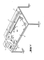
- the device shown in Fig. 1 comprises a measuring table 1 and on this a measuring bridge 2 with a measuring carriage 3, four clamping blocks 4 for holding a sheet 5 to be measured, an electronic part 6 and a personal computer 7.
- the plate of the table 1 is made of wood and has a sheet steel layer under an uppermost cover layer, which allows the printed sheet 5 to be held in place by means of magnets or the like.
- the electronic part 6 is designed as a plug-in module.
- the personal computer 7 provided with an integrated screen terminal is rotatably mounted on the table. Measuring car 3, electronic part 6 and personal computer 7 are connected via lines, not shown.
- the electronic part 6 comprises a microprocessor system and interfaces for processing the supplied and the measurement and control signals generated by it.
- the processor system in the electronic part works with the personal computer 7 in the so-called master-slave mode, the personal computer having the control function and evaluating the measured and entered data, while the system in the electronic part for carrying out the measurements and Movements of the measuring carriage is responsible (see also Fig. 8).
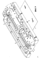
- the measuring bridge 2 is shown larger. It comprises two vertical side parts 11 and 12, which carry the other parts of the bridge, and two cover hoods 13 and 14, which cover the space between the two side parts and are pivotably mounted on them, so that they move into the position shown in FIG. 3 can be unfolded and give access to the inner parts of the measuring bridge.
- the two side parts 11 and 12 are connected to one another by a guide shaft 15 and a connecting rod 16, which is only indicated in the drawing.
- the measuring carriage 3 On the guide shaft 15, the measuring carriage, designated as a whole by 3, can be moved back and forth and pivoted about the shaft.
- the measuring carriage 3 consists of a guide block 17 provided with two ball bushings and two measuring heads 18 and 19 fastened to it and a guide or hold-down plate 20 which is angled upwards on both sides.
- the measuring carriage is provided with rollers 21 and two spring-loaded hold-down clamps 22 (FIG . 4 and 5). In operation, the measuring carriage is supported with its rollers 21 on the printed sheet 5 to be measured, whereby the distance between the measuring heads 18 and 19 and the individual fields MF of the measuring strip MS located on the printed sheet 5 is always constant.
- the measuring heads are in principle of the type described in US-A-4078858, wherein the measuring head 19 measures three color channels simultaneously, while the other measuring head 18 is only designed as a single channel, but is instead equipped with filters that can be changed manually or, if necessary, under program control.
- the measuring head 18 is intended for special cases for measuring house and spot colors, but in the normal case, as will be explained further below, the simultaneous measuring head 19 is always used.
- a toothed belt 23 is provided, which is guided over two rollers or rollers 24 and 25 rotatably mounted on each of the side parts 11 and 12 and on whose lower run the guide block 17 is fastened.
- the left-hand roller 25 in FIG. 3 is driven by a stepping motor 27 via a toothed belt reduction gear 26, which is only indicated by broken lines.
- the other roller 24 is freely rotatable in a clamping device 28.
- Stepper motor 27 and gear 26 are dimensioned such that the toothed belt 23 and thus the measuring carriage 3 are transported further by 0.1 mm per complete motor step.
- a guide profile 29 is arranged in the rear cover 13, in which the electrical flat conductor connection, not shown, of the measuring carriage 3 with the electronic part 6 runs.
- On the side parts 11 and 12 are also indicated by blocks 30 quick-release fasteners for fixing the two covers 13 and 14 in the folded-up closed position and a fork light barrier 31 each, which with a sheet metal strip, not shown, or the like. on the guide block 17 or measuring carriage 3 cooperates in such a way that the measuring carriage is automatically stopped when it hits one or the other side part, e.g. B. comes closer than a certain minimum distance due to a control error.
- a cross-sectionally U-shaped holder 32 is fastened in the front cover 14, in which five marker lamps 33 are arranged which are distributed uniformly over the length of the measuring bridge.
- These lamps each consist of a light source in the form of a so-called line lamp 33a in the outside Leg of the bracket, and P rojekomsoptik 33b in the lower support leg and generate aur the print sheet 5 in a five line lying marking lines of light 34, each about 20 mm in length.
- the beam paths of the lamps 33 are indicated in FIG. 2 by the dashed lines 34a.
- the light lines serve to align the printed sheet 5 such that the measuring strip MS comes to lie exactly below the path of movement of the two measuring heads 18 and 19.
- the projection optics 33b are mounted eccentrically and rotatably arranged in the holder. Instead of the lines of light, light spots or crosses or the like can of course also be provided as markings.
- a switching rocker 35 is provided on the top of the front cover 14, by means of which the measuring carriage 3 can be moved manually controlled into the desired measuring position along the measuring strip MS.
- the hold-down plate 20 is provided with a sighting window 36 (FIG. 5), the contour of which forms a pointer 37, which is in fixed spatial association with the optical axes of the two measuring heads 18 and 19, designated 38 and 39 stands.
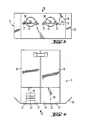
- FIGS. 9 and 10 The structure of the magnetic terminal blocks 4 is shown in FIGS. 9 and 10.
- Each block 4 comprises two arch stops 4a.
- the armature 4b of a hold-down magnet 4c is arranged between them and can be pivoted about a horizontal axis 4d.
- a vertical pin 4e is slidably mounted, which is mechanically coupled to the armature 4b and visually indicates the armature position.
- the magnet 4c When the magnet 4c is acted on with tension, it pulls the armature 4b up and at the same time presses a resilient pressing member 4f down on the armature 4b, as a result of which a possibly struck printed sheet is clamped.
- the arc clamping blocks 4 are actuated automatically via electronic part 6 before the measuring carriage 3 is set in motion.
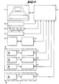
- FIG. 8 shows a basic block circuit diagram of the electrical parts of the device, insofar as it is necessary to understand how they work. It is understood that what is shown is purely exemplary and that the individual functions of the device could also be easily implemented by other implementations.
- the central part of the circuit is the personal computer 7.
- the personal computer is connected to the microprocessor system of the electronic part 6, to which the remaining electrical and electronic assemblies and parts of the device are in turn connected via lines that are not specified.
- These are the rocker 35 for manual control of the test vehicle.
- analog-digital converters are also provided on all analog-digital transitions.
- the basic apparatus structure of the device and its basic mode of operation correspond to those of the known devices of this type, for example the device shown in great detail in US Pat. No. 3,995,958: the measuring carriage 3 is operated manually or automatically guided along the measuring strip MS to be examined on the printed sheet 5, and the remission values detected by the (respectively active) measuring head 18 or 19 are processed or evaluated in electronics (here electronic part 6 and personal computer 7).
- One of the basic ideas of the method according to the invention is to divide the measuring process into two phases, namely into a so-called detection run and one or more subsequent measuring runs.
- the recognition run carried out first in time, the color measuring strips, which are initially unknown to the device, are scanned in short successive intervals and the structure of the measuring strip and the most suitable measuring positions in the strip are determined from the sample values obtained in the process.
- the color densities at the measurement positions determined during the recognition run are measured on any number of printed sheets with the same color measurement strips and are used for evaluation. With the first printed sheet, the measurement run can of course also be carried out together with the recognition run.
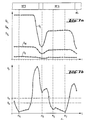
- FIG. 6a shows a section of a typical density curve as it arises when a measuring strip MS is scanned periodically during the recognition run, the increments of indexing of the measuring carriage or measuring head indexed with i being plotted along the measuring strip MS on the abscissa.
- the three curves D M , Dy and D c show the course of the simultaneously measured density values DM "Dy.
- D co for the three colors magenta, yellow and cyan in the individual sampling points i for the measuring fields of the measuring strip section MS designated here with MF1 to MF4 .
- the density profiles within the individual measuring fields MF have more or less pronounced flat areas, while they have relatively steep flanks at the transitions between the individual measuring fields.
- the centers of these flat spots are obviously possible measuring positions for the measuring runs.
- the analysis of the measuring strip structure during the recognition run is now based on the determination of these flat points of the density profiles in accordance with the second essential basic idea of the invention.
- the correct measuring positions are selected from all the flat points, which are still to be described, and thus, in principle, possible measuring positions by taking into account a predetermined minimum measuring field length and preventing multiple measuring positions from being assigned to longer measuring fields.
- the qualitative type (color, grid type, etc.) of the measuring fields can be followed.
- the unknown measuring strip is divided into overlapping intervals of the same length, with a new interval j consisting of n sampling points beginning at each sampling point i.
- the length (n-1) times the distance between two sampling points i of the intervals j preferably corresponds approximately to the difference between the minimum field length possible by the measuring optics and the diameter of the measuring spot of the measuring head.
- the standard deviations in each interval or the sum of the absolute values of the deviations of the density measured values from the mean density value in each interval are now formed.
- the three standard deviations or absolute value sums are summed in the three colors for each interval or the maximum standard deviation or absolute value sum is selected for each interval. The value found in this way is designated Xj.
- 7b shows e.g. B. that relative minima of the X j course even with gaps between two measuring fields -here z. B. between the designated with MF 5 and MF 6 - or occur in very narrow, only for visual control fields or that within a single measuring field - here MF 6- z. B. several minima may occur as a result of inhomogeneities.
- the type of measuring strip to be analyzed is known to the device or if the measuring strip to be recognized is composed of individual pieces of known measuring strip types, known correlation or comparison methods can be used for the fully automatic type determination.
- the device If the measuring strip is unknown, the device must be given certain information about the types of measuring field occurring before the recognition run. The device then tries to determine the geometric structure of the strip and the types of all measurement fields during the recognition run. Measuring fields that are not recognized or cannot be determined must then be defined or specified by hand.
- a semi-automatic measurement field determination would be e.g. B. also possible by entering the density setpoints with corresponding tolerances for all occurring measuring field types before the detection run.
- the recognition run can of course also be carried out manually controlled.
- the measuring head is successively positioned manually on the individual measuring fields and at the same time the necessary information about the relevant measuring field type is entered via the keyboard.
- the density values and the measuring position are automatically determined or recorded.
- a recognition run can be dispensed with. In order to take into account any paper distortion, only the positions of the first and last measuring field are entered manually.
- the actual measuring phase takes place.
- the measuring fields or measuring field types of interest are entered (masking the measuring field strip). From these input data and the possible measurement positions obtained during the recognition run, those are then selected at which measurements are actually to be carried out (in extreme cases, of course, these can also be all measurement fields). And finally, the measuring carriage is then guided evenly over the measuring strip and the color densities in the three color channels are determined simultaneously at all points of interest.
- the measured values are processed by the electronic part 6 and then forwarded to the personal computer 7 for processing or evaluation.
- the actual processing of the measurement data itself is not the subject of the invention.
- the detection and measurement runs are not necessarily separate, i. H. must be carried out in two separate runs, but can of course also be done together.
- the actual measurement can also z. B. may also take place when the measuring carriage returns after the detection run. Since the recognition run is usually only carried out once for each color measuring strip, this question is of minor importance.
- the measuring carriage 3 is equipped with an additional measuring head 18 for special colors.
- These so-called decorative or house colors which are often used in printing technology, have a different spectral composition than the standard printing inks and consequently require specially matched measuring filters so that a sufficiently high measuring signal is achieved.
- the additional or "piggyback" measuring head 18 now makes it possible to measure standard printing inks and special printing inks with the same precision.
- the computer is advised in the start dialog which color field (color) should be measured with which filter.
- the selection of the corresponding filter is then computer-controlled, as is the switchover from the normal simultaneous measuring head 19 to the additional measuring head 18 and vice versa.
- EAN codes European article numbering
- EAN codes have certain requirements that are set out in standards.
- the bar codes themselves and / or test marks specified in standards are suitable for checking the codes.
- the testing (of the print quality) of these codes takes place today by means of hand-held test devices, in which a laser is guided over the test marks or over the EAN code.
- the measuring processes for code checking and color measuring strips are carried out independently and take a lot of time.
- the additional measuring head 18 is now designed as a barcode reader, whereby it can possibly be articulated and / or telescopically connected to the simultaneous measuring head 19, so that it can easily be set to EAN codes present in the image of the printed sheet .
- the analysis of the EAN check marks contained in the print control strip is carried out analogously to the measuring fields of the color measuring strip, i. H. the position of the measuring positions is determined in a recognition or positioning run and the actual density measurement is then carried out in a separate measuring run, for which the same applies as what was said for the evaluation of the color measuring strip.
- the scanning of color measuring strips and EAN test marks can of course be carried out simultaneously or at different times. The actual checking of the code then takes place in the computer and is not the subject of the present application.
Claims (22)
procédé caractérisé en ce que, pour la détermination des positions de mesure,
caractérisé en ce que
Priority Applications (1)
| Application Number | Priority Date | Filing Date | Title |
|---|---|---|---|
| AT82810142T ATE15271T1 (de) | 1981-04-03 | 1982-03-30 | Verfahren und vorrichtung zur farbmetrischen analyse eines gedruckten farbmessstreifens. |
Applications Claiming Priority (2)
| Application Number | Priority Date | Filing Date | Title |
|---|---|---|---|
| CH228381 | 1981-04-03 | ||
| CH2283/81 | 1981-04-03 |
Publications (2)
| Publication Number | Publication Date |
|---|---|
| EP0064024A1 EP0064024A1 (fr) | 1982-11-03 |
| EP0064024B1 true EP0064024B1 (fr) | 1985-08-28 |
Family
ID=4230148
Family Applications (1)
| Application Number | Title | Priority Date | Filing Date |
|---|---|---|---|
| EP82810142A Expired EP0064024B1 (fr) | 1981-04-03 | 1982-03-30 | Procédé et dispositif pour l'analyse colorimétrique d'une bande de mesure d'impression colorée |
Country Status (11)
| Country | Link |
|---|---|
| US (1) | US4505589A (fr) |
| EP (1) | EP0064024B1 (fr) |
| JP (1) | JPS58739A (fr) |
| AT (1) | ATE15271T1 (fr) |
| AU (1) | AU556480B2 (fr) |
| CA (1) | CA1171298A (fr) |
| DE (1) | DE3265740D1 (fr) |
| DK (1) | DK156923C (fr) |
| ES (1) | ES8305128A1 (fr) |
| NO (1) | NO158358C (fr) |
| ZA (1) | ZA822290B (fr) |
Cited By (3)
| Publication number | Priority date | Publication date | Assignee | Title |
|---|---|---|---|---|
| DE102008022013A1 (de) * | 2008-05-02 | 2009-11-12 | Basf Coatings Ag | Verfahren zur Messung der Wolkigkeit von Lackierungen auf Prüftafeln |
| US8047089B2 (en) | 2006-11-20 | 2011-11-01 | Heidelberger Druckmachinen Ag | Device for the optical measurement of a printed sheet and method for operating the device |
| DE102007051582B4 (de) | 2006-11-20 | 2018-03-08 | Heidelberger Druckmaschinen Ag | Verfahren zum Betreiben einer Vorrichtung zum optischen Messen eines Druckbogens |
Families Citing this family (95)
| Publication number | Priority date | Publication date | Assignee | Title |
|---|---|---|---|---|
| DE3219743C2 (de) * | 1982-05-26 | 1985-01-10 | Heidelberger Druckmaschinen Ag, 6900 Heidelberg | Verfahren zur farbmetrischen Auswertung eines auf der Schöndruck- und auf der Widerdruckseite in einem Maschinendurchgang bedruckten Bogens |
| ATE26674T1 (de) * | 1983-01-29 | 1987-05-15 | Roland Man Druckmasch | Vorrichtung zum ermitteln und auswerten von farbmessfeldern auf einem druckbogen. |
| DE3324951A1 (de) * | 1983-07-11 | 1985-01-24 | M.A.N.- Roland Druckmaschinen AG, 6050 Offenbach | Vorrichtung zum ermitteln und auswerten von farbmessfeldern auf einem auf einem messtisch liegenden druckbogen mit einem densitometer |
| EP0143744B1 (fr) * | 1983-11-04 | 1988-01-13 | GRETAG Aktiengesellschaft | Procédé et dispositif d'analyse de qualité d'impression et/ou de réglage d'encre dans une rotative offset et rotative offset équipée d'un tel dispositif |
| US4660159A (en) * | 1983-11-04 | 1987-04-21 | Gretag Aktiengesellschaft | Process and apparatus for the regulation of ink feed controls in an offset printing machine |
| GB8330869D0 (en) * | 1983-11-18 | 1983-12-29 | Centurfax Ltd | Page make-up system |
| EP0149424B1 (fr) * | 1983-12-19 | 1990-11-14 | GRETAG Aktiengesellschaft | Procédé et dispositif pour le contrôle de la qualité d'impression et ruban test coloré pour ce contrôle |
| JPS60154124A (ja) * | 1984-01-24 | 1985-08-13 | Omron Tateisi Electronics Co | 色情報検知器 |
| US4654794A (en) * | 1984-02-18 | 1987-03-31 | Colorgen, Inc. | Methods for determining the proper coloring for a tooth replica |
| US4583186A (en) * | 1984-03-26 | 1986-04-15 | Bremson Data Systems | Computerized video imaging system |
| USRE33244E (en) * | 1984-03-26 | 1990-06-26 | Bremson Data Systems | Computerized video imaging system |
| JP2548692B2 (ja) * | 1984-10-23 | 1996-10-30 | 凸版印刷 株式会社 | 複数段の印刷管理用スケ−ルの濃度値判別方法 |
| US4900148A (en) * | 1985-12-09 | 1990-02-13 | Nabisco Brands, Inc. | Apparatus and process for measuring an optical characteristic of a predetermined portion of a flat object |
| ATE47564T1 (de) * | 1985-12-10 | 1989-11-15 | Heidelberger Druckmasch Ag | Verfahren zur farbauftragssteuerung bei einer druckmaschine, entsprechend ausgeruestete druckanlage und messvorrichtung fuer eine solche druckanlage. |
| US5182721A (en) * | 1985-12-10 | 1993-01-26 | Heidelberger Druckmaschinen Aktiengesellschaft | Process and apparatus for controlling the inking process in a printing machine |
| US4717258A (en) * | 1985-12-31 | 1988-01-05 | Smith College | 3-channel microdensitometer for analysis of plate spectra |
| US4730930A (en) * | 1986-06-24 | 1988-03-15 | Technical Arts Corporation | Scanning apparatus and method |
| ES2028127T3 (es) * | 1986-08-29 | 1992-07-01 | Gretag Aktiengesellschaft | Dispositivo de guia para cables. |
| JP2657914B2 (ja) * | 1986-12-08 | 1997-09-30 | 株式会社 小森コーポレーション | 走査濃度計の測定位置同期方法 |
| DE3643721A1 (de) * | 1986-12-20 | 1988-06-30 | Heidelberger Druckmasch Ag | Druckkontrollstreifen |
| DE3643720C2 (de) * | 1986-12-20 | 1994-03-10 | Heidelberger Druckmasch Ag | Verfahren zum Ermitteln von Steuer- /Regelgrößen für das Farbwerk von Druckmaschinen |
| US4947348A (en) * | 1987-03-25 | 1990-08-07 | Kollmorgen Corporation | Densitometer method and system for identifying and analyzing printed targets |
| US4853879A (en) * | 1987-04-03 | 1989-08-01 | Matzoll Jr Robert J | Automated paint film characterization system |
| DE3738850A1 (de) * | 1987-11-16 | 1989-05-24 | Roland Man Druckmasch | Verfahren zur automatischen positionsfindung von druckkontrollstreifen fuer automatisch messende farbdichtemessanlagen |
| US4967379A (en) * | 1987-12-16 | 1990-10-30 | Gretag Aktiengesellschaft | Process for the ink control or regulation of a printing machine by comparing desired color to obtainable color data |
| US4975862A (en) * | 1988-01-14 | 1990-12-04 | Gretag Aktiengesellschaft | Process and apparatus for the ink control of a printing machine |
| US4959790A (en) * | 1988-06-28 | 1990-09-25 | F & S Corporation Of Columbus, Georgia | Apparatus and method for producing color corrected reproduction of colored original images |
| DE3826385A1 (de) * | 1988-08-03 | 1990-02-08 | Roland Man Druckmasch | Vorrichtung zum auswerten von druckvorlagen |
| JPH089615Y2 (ja) * | 1988-09-05 | 1996-03-21 | 大日本スクリーン製造株式会社 | 印刷濃度測定装置 |
| DE3830731A1 (de) * | 1988-09-09 | 1990-03-22 | Heidelberger Druckmasch Ag | Vorrichtung zur farbmessung |
| JPH02103446A (ja) * | 1988-10-12 | 1990-04-16 | Maruzen Petrochem Co Ltd | 濃度パターン解析装置 |
| ATE142561T1 (de) * | 1988-11-23 | 1996-09-15 | Komori Printing Mach | Verfahren zum auswerten des farbmessstreifens bei selbsttätiger densitometrischer farbsteuerung |
| US5118183A (en) * | 1989-02-10 | 1992-06-02 | X-Rite, Incorporated | Automated strip reader densitometer |
| US5073857A (en) * | 1989-06-01 | 1991-12-17 | Accuron Corporation | Method and apparatus for cell analysis |
| US5077806A (en) * | 1989-06-01 | 1991-12-31 | Accuron Corporation | Machine vision analysis apparatus |
| US5073028A (en) * | 1990-04-23 | 1991-12-17 | X-Rite, Incorporated | Scanning densitometer |
| US5202767A (en) * | 1990-12-26 | 1993-04-13 | Pathology Imaging Corporation | Multimode computerized multicolor camera and method therefor |
| US5402361A (en) * | 1991-04-18 | 1995-03-28 | X-Rite, Incorporated | Apparatus for method for logging, storing, and redirection of process related non-densitometric data generated by color processing equipment for use by an off site host computer |
| JP2526454B2 (ja) * | 1991-10-31 | 1996-08-21 | 株式会社島津製作所 | 分光光度計の試料室 |
| US5841955A (en) * | 1991-12-02 | 1998-11-24 | Goss Graphic Systems, Inc. | Control system for a printing press |
| US6100982A (en) * | 1991-12-24 | 2000-08-08 | Tobias Associates, Inc. | Method and apparatus for determining a scanning track for a narrow color bar |
| US5495429A (en) * | 1993-02-12 | 1996-02-27 | West Virginia University | Method and apparatus for measuring the color of three dimensional objects |
| US5369494A (en) * | 1993-04-12 | 1994-11-29 | X-Rite, Incorporated | Portable scanning colorimeter |
| JPH07110263A (ja) * | 1993-10-08 | 1995-04-25 | Yazaki Corp | コネクタ内端子の識別方法及び装置 |
| US5812705A (en) * | 1995-02-28 | 1998-09-22 | Goss Graphic Systems, Inc. | Device for automatically aligning a production copy image with a reference copy image in a printing press control system |
| DE19511076C1 (de) * | 1995-03-25 | 1996-05-23 | Roland Man Druckmasch | Verfahren zum Feststellen von Farbverschmutzungen beim Herstellen mehrfarbiger Druckexemplare auf Druckmaschinen |
| US5767980A (en) * | 1995-06-20 | 1998-06-16 | Goss Graphic Systems, Inc. | Video based color sensing device for a printing press control system |
| US5805280A (en) * | 1995-09-28 | 1998-09-08 | Goss Graphic Systems, Inc. | Control system for a printing press |
| US5903712A (en) * | 1995-10-05 | 1999-05-11 | Goss Graphic Systems, Inc. | Ink separation device for printing press ink feed control |
| US5966205A (en) * | 1997-07-01 | 1999-10-12 | Lj Laboratories, Llc | Method and apparatus for detecting and preventing counterfeiting |
| US5759030A (en) * | 1996-01-02 | 1998-06-02 | Lj Laboratories, L.L.C. | Method for determing optical characteristics of teeth |
| US6239868B1 (en) | 1996-01-02 | 2001-05-29 | Lj Laboratories, L.L.C. | Apparatus and method for measuring optical characteristics of an object |
| US5880826A (en) | 1997-07-01 | 1999-03-09 | L J Laboratories, L.L.C. | Apparatus and method for measuring optical characteristics of teeth |
| US6307629B1 (en) | 1997-08-12 | 2001-10-23 | Lj Laboratories, L.L.C. | Apparatus and method for measuring optical characteristics of an object |
| US5745229A (en) * | 1996-01-02 | 1998-04-28 | Lj Laboratories, L.L.C. | Apparatus for determining optical characteristics of an object |
| US6118521A (en) * | 1996-01-02 | 2000-09-12 | Lj Laboratories, L.L.C. | Apparatus and method for measuring optical characteristics of an object |
| US5926262A (en) * | 1997-07-01 | 1999-07-20 | Lj Laboratories, L.L.C. | Apparatus and method for measuring optical characteristics of an object |
| US6254385B1 (en) | 1997-01-02 | 2001-07-03 | Lj Laboratories, Llc | Apparatus and method for measuring optical characteristics of teeth |
| US6373573B1 (en) * | 2000-03-13 | 2002-04-16 | Lj Laboratories L.L.C. | Apparatus for measuring optical characteristics of a substrate and pigments applied thereto |
| IT1284432B1 (it) * | 1996-03-22 | 1998-05-21 | De La Rue Giori Sa | Procedimento di controllo automatico della qualita' di stampa di un'immagine policroma |
| US5739914A (en) * | 1996-11-12 | 1998-04-14 | Yokogawa Instrument Corporation | Colorimetric instrument |
| US6233047B1 (en) | 1997-01-02 | 2001-05-15 | Lj Laboratories, L.L.C. | Apparatus and method for measuring optical characteristics of an object |
| US6301004B1 (en) | 2000-05-31 | 2001-10-09 | Lj Laboratories, L.L.C. | Apparatus and method for measuring optical characteristics of an object |
| DE19716066C1 (de) * | 1997-04-17 | 1998-09-10 | Techkon Elektronik Gmbh | Handmeßgerät für Reflexionsmessungen auf Druckbogen und Testformen |
| US6501542B2 (en) | 1998-06-30 | 2002-12-31 | Lj Laboratories, Llc | Apparatus and method for measuring optical characteristics of an object |
| US6449041B1 (en) | 1997-07-01 | 2002-09-10 | Lj Laboratories, Llc | Apparatus and method for measuring optical characteristics of an object |
| US6870616B2 (en) * | 1998-06-30 | 2005-03-22 | Jjl Technologies Llc | Spectrometer apparatus for determining an optical characteristic of an object or material having one or more sensors for determining a physical position or non-color property |
| US6271913B1 (en) | 1997-07-01 | 2001-08-07 | Lj Laboratories, Llc | Apparatus and method for measuring optical characteristics of an object |
| US6246471B1 (en) | 1998-06-08 | 2001-06-12 | Lj Laboratories, Llc | Apparatus and method for measuring optical characteristics of an object |
| US6246479B1 (en) | 1998-06-08 | 2001-06-12 | Lj Laboratories, L.L.C. | Integrated spectrometer assembly and methods |
| US6573984B2 (en) | 1998-06-30 | 2003-06-03 | Lj Laboratories Llc | Apparatus and method for measuring optical characteristics of teeth |
| US6249348B1 (en) * | 1998-11-23 | 2001-06-19 | Lj Laboratories, L.L.C. | Integrated spectrometer assembly and methods |
| US6538726B2 (en) | 1998-07-10 | 2003-03-25 | Lj Laboratories, Llc | Apparatus and method for measuring optical characteristics of an object |
| DE59915109D1 (de) | 1999-07-06 | 2010-01-21 | X Rite Europe Gmbh | Lichtmessvorrichtung |
| DE29916379U1 (de) * | 1999-09-17 | 1999-12-09 | Roland Man Druckmasch | Vorrichtung zum densitometrischen Ausmessen von Druckprodukten |
| US6519037B2 (en) | 1999-12-23 | 2003-02-11 | Lj Laboratories, Llc | Spectrometer having optical unit including a randomized fiber optic implement |
| US6362888B1 (en) | 1999-12-23 | 2002-03-26 | Lj Laboratories, L.L.C. | Spectrometer assembly |
| US6414750B2 (en) | 2000-01-10 | 2002-07-02 | Lj Laboratories, L.L.C. | Spectrometric apparatus and method for measuring optical characteristics of an object |
| US6499402B1 (en) | 2000-05-17 | 2002-12-31 | Web Printing Controls Co., Inc. | System for dynamically monitoring and controlling a web printing press |
| EP1180898B1 (fr) * | 2000-08-11 | 2006-10-04 | Gretag-Macbeth AG | Méthode et dispositif pour la mesure colorimétrique d'un document bidimensionnel |
| US6903813B2 (en) | 2002-02-21 | 2005-06-07 | Jjl Technologies Llc | Miniaturized system and method for measuring optical characteristics |
| US7173705B2 (en) * | 2003-02-26 | 2007-02-06 | Hamamatsu Photonics K.K. | Measuring device for immunochromatography test piece |
| JP4280615B2 (ja) * | 2003-12-09 | 2009-06-17 | 富士フイルム株式会社 | 調整量測定装置および調整量測定プログラム |
| US7345763B2 (en) * | 2004-04-30 | 2008-03-18 | X-Rite, Inc. | Method for operating a color measurement system |
| CN100586712C (zh) * | 2006-03-06 | 2010-02-03 | 海德堡印刷机械股份公司 | 识别颜色测量条的方法 |
| EP1936337B1 (fr) * | 2006-12-21 | 2010-06-02 | X-Rite Europe GmbH | Tête manométrique et dispositif de balayage et dispositif de balayage équipé de celle-ci |
| DE102007008017A1 (de) * | 2007-02-15 | 2008-08-21 | Gretag-Macbeth Ag | Farbspaltungskorrekturverfahren |
| EP2199765B1 (fr) | 2008-12-18 | 2013-10-16 | X-Rite Europe GmbH | Procédé et appareil de mesure de couleur manuelle destinés à la mesure d'une échelle de mesure de couleur |
| US8736840B1 (en) * | 2010-05-23 | 2014-05-27 | Arkady Ten | Method for finding an aim position of a measuring device |
| DE102011102452B4 (de) | 2010-06-18 | 2024-04-25 | Heidelberger Druckmaschinen Ag | Bestimmung von Messfeldbreiten bei Farbmessgeräten |
| JP2012152974A (ja) * | 2011-01-25 | 2012-08-16 | Komori Corp | 印刷機のインキ供給量制御装置 |
| US20150028876A1 (en) * | 2013-07-24 | 2015-01-29 | Nathan McLaughlin | Method and apparatus for testing a lighting device under temperature |
| WO2016047378A1 (fr) * | 2014-09-26 | 2016-03-31 | 富士フイルム株式会社 | Procédé de présentation de position de mesure, procédé de production de guide de présentation de position de mesure, procédé de mesure de matière imprimée, procédé de détermination de position de mesure de matière imprimée, et dispositif de détermination de position de mesure de matière imprimée |
| DE102015216264A1 (de) * | 2015-08-26 | 2017-03-02 | Koenig & Bauer Ag | Druckmessstreifen und Anwendungsverfahren dafür |
| DE102016201123A1 (de) * | 2016-01-27 | 2017-07-27 | Koenig & Bauer Ag | Verfahren zum Vergleichen eines gedruckten Farbmessstreifens mit einem Muster |
Citations (1)
| Publication number | Priority date | Publication date | Assignee | Title |
|---|---|---|---|---|
| EP0011376A1 (fr) * | 1978-10-13 | 1980-05-28 | Philip Emanuel Tobias | Système de densitomètre photoélectrique |
Family Cites Families (2)
| Publication number | Priority date | Publication date | Assignee | Title |
|---|---|---|---|---|
| US3995958A (en) * | 1975-07-21 | 1976-12-07 | Hallmark Cards, Incorporated | Automatic densitometer and method of color control in multi-color printing |
| US4003660A (en) * | 1975-12-03 | 1977-01-18 | Hunter Associates Laboratory, Inc. | Sensing head assembly for multi-color printing press on-line densitometer |
-
1982
- 1982-03-30 US US06/363,538 patent/US4505589A/en not_active Expired - Lifetime
- 1982-03-30 AT AT82810142T patent/ATE15271T1/de not_active IP Right Cessation
- 1982-03-30 DE DE8282810142T patent/DE3265740D1/de not_active Expired
- 1982-03-30 EP EP82810142A patent/EP0064024B1/fr not_active Expired
- 1982-03-31 CA CA000400081A patent/CA1171298A/fr not_active Expired
- 1982-04-02 ES ES511114A patent/ES8305128A1/es not_active Expired
- 1982-04-02 JP JP57053996A patent/JPS58739A/ja active Granted
- 1982-04-02 AU AU82299/82A patent/AU556480B2/en not_active Ceased
- 1982-04-02 DK DK153182A patent/DK156923C/da not_active IP Right Cessation
- 1982-04-02 NO NO821126A patent/NO158358C/no unknown
- 1982-04-02 ZA ZA822290A patent/ZA822290B/xx unknown
Patent Citations (1)
| Publication number | Priority date | Publication date | Assignee | Title |
|---|---|---|---|---|
| EP0011376A1 (fr) * | 1978-10-13 | 1980-05-28 | Philip Emanuel Tobias | Système de densitomètre photoélectrique |
Cited By (3)
| Publication number | Priority date | Publication date | Assignee | Title |
|---|---|---|---|---|
| US8047089B2 (en) | 2006-11-20 | 2011-11-01 | Heidelberger Druckmachinen Ag | Device for the optical measurement of a printed sheet and method for operating the device |
| DE102007051582B4 (de) | 2006-11-20 | 2018-03-08 | Heidelberger Druckmaschinen Ag | Verfahren zum Betreiben einer Vorrichtung zum optischen Messen eines Druckbogens |
| DE102008022013A1 (de) * | 2008-05-02 | 2009-11-12 | Basf Coatings Ag | Verfahren zur Messung der Wolkigkeit von Lackierungen auf Prüftafeln |
Also Published As
| Publication number | Publication date |
|---|---|
| ATE15271T1 (de) | 1985-09-15 |
| DE3265740D1 (en) | 1985-10-03 |
| NO158358B (no) | 1988-05-16 |
| ES511114A0 (es) | 1983-04-01 |
| DK156923B (da) | 1989-10-16 |
| DK156923C (da) | 1990-03-12 |
| ZA822290B (en) | 1983-02-23 |
| NO158358C (no) | 1988-08-24 |
| JPS58739A (ja) | 1983-01-05 |
| AU556480B2 (en) | 1986-11-06 |
| JPH041293B2 (fr) | 1992-01-10 |
| DK153182A (da) | 1982-10-04 |
| AU8229982A (en) | 1982-10-07 |
| ES8305128A1 (es) | 1983-04-01 |
| EP0064024A1 (fr) | 1982-11-03 |
| US4505589A (en) | 1985-03-19 |
| NO821126L (no) | 1982-10-04 |
| CA1171298A (fr) | 1984-07-24 |
Similar Documents
| Publication | Publication Date | Title |
|---|---|---|
| EP0064024B1 (fr) | Procédé et dispositif pour l'analyse colorimétrique d'une bande de mesure d'impression colorée | |
| EP0149424B1 (fr) | Procédé et dispositif pour le contrôle de la qualité d'impression et ruban test coloré pour ce contrôle | |
| DE3830732C2 (de) | Verfahren zur Feuchtmittelführung bei einer Offset-Druckmaschine | |
| EP0884182B1 (fr) | Procédé de regulation des operations effectuées par une machine d'impression | |
| EP0135700B1 (fr) | Procédé de réglage de l'encrier d'une machine à imprimer | |
| DE8605667U1 (de) | Schnittholz-Prüfvorrichtung | |
| DE3830731A1 (de) | Vorrichtung zur farbmessung | |
| DE2253189B2 (de) | Verfahren und Vorrichtung zur maschinellen Kontrolle der Farbdichte von auf eine laufende Bahn aufgebrachten Druckfarben | |
| DE1941057A1 (de) | Einrichtung zur Lageeinstellung eines Gegenstandes relativ zu einem Bezugspunkt | |
| DE2921862A1 (de) | Maschine fuer die automatische qualitaetskontrolle an frisch gedruckten banknoten und wertpapieren | |
| EP0993947A1 (fr) | Procédé et dispositif pour mesurer optiquement la position d'impression et/ou la déviation de registre entre les différentes couleurs dans une machine à imprimer en plusieurs couleurs | |
| DE3148076C2 (fr) | ||
| DE2537343C3 (de) | Verfahren zur densitometrischen Messung einer auf einem Trägermaterial entwickelten Substanzzone und Densitometer zur Durchführung des Verfahrens | |
| DE3219743A1 (de) | Verfahren zur farbmetrischen auswertung eines beiderseits bedruckten bogens | |
| EP0388697A2 (fr) | Procédé et dispositif pour la fixation d'un champ de mesure pour la détermination de l'épaisseur de la couche de mouillage d'une plaque d'impression offset | |
| EP0925917A1 (fr) | Système de mesure | |
| DE2901980C2 (de) | Einrichtung zum Steuern des Farbwerkes einer Bogenoffsetdruckmaschine | |
| DE2738575C2 (fr) | ||
| EP0860276B1 (fr) | Procédé et dispositif de contrôle de qualité | |
| DE3801860C2 (de) | Vorrichtung zur Untersuchung einer Oberfläche eines fortlaufend bewegten Bandmaterials | |
| DE2713004A1 (de) | Lage-messwertgeber fuer werkzeugmaschinen und messvorrichtungen oder -maschinen | |
| DE4301272A1 (de) | Vorrichtung zur Bestimmung des Registerfehlers zwischen den einzelnen Farben beim Mehrfarbendruck in einer Langbahn-Rollenrotationsdruckmaschine | |
| EP0434072A2 (fr) | Bande de contrôle d'impression | |
| EP0311729A1 (fr) | Procédé et dispositif pour le positionnement d'éléments d'impression cylindriques dans une machine d'impression avec au moins deux stations d'impression | |
| DE3736629C2 (fr) |
Legal Events
| Date | Code | Title | Description |
|---|---|---|---|
| PUAI | Public reference made under article 153(3) epc to a published international application that has entered the european phase |
Free format text: ORIGINAL CODE: 0009012 |
|
| 17P | Request for examination filed |
Effective date: 19820401 |
|
| AK | Designated contracting states |
Designated state(s): AT CH DE FR GB IT NL SE |
|
| ITF | It: translation for a ep patent filed |
Owner name: SOCIETA' ITALIANA BREVETTI S.P.A. |
|
| RAP1 | Party data changed (applicant data changed or rights of an application transferred) |
Owner name: GRETAG AKTIENGESELLSCHAFT Owner name: HEIDELBERGER DRUCKMASCHINEN AKTIENGESELLSCHAFT |
|
| GRAA | (expected) grant |
Free format text: ORIGINAL CODE: 0009210 |
|
| AK | Designated contracting states |
Designated state(s): AT CH DE FR GB IT LI NL SE |
|
| REF | Corresponds to: |
Ref document number: 15271 Country of ref document: AT Date of ref document: 19850915 Kind code of ref document: T |
|
| REF | Corresponds to: |
Ref document number: 3265740 Country of ref document: DE Date of ref document: 19851003 |
|
| ET | Fr: translation filed | ||
| PLBE | No opposition filed within time limit |
Free format text: ORIGINAL CODE: 0009261 |
|
| STAA | Information on the status of an ep patent application or granted ep patent |
Free format text: STATUS: NO OPPOSITION FILED WITHIN TIME LIMIT |
|
| 26N | No opposition filed | ||
| ITTA | It: last paid annual fee | ||
| EAL | Se: european patent in force in sweden |
Ref document number: 82810142.8 |
|
| PGFP | Annual fee paid to national office [announced via postgrant information from national office to epo] |
Ref country code: CH Payment date: 19960607 Year of fee payment: 15 |
|
| PG25 | Lapsed in a contracting state [announced via postgrant information from national office to epo] |
Ref country code: LI Effective date: 19970331 Ref country code: CH Effective date: 19970331 |
|
| REG | Reference to a national code |
Ref country code: CH Ref legal event code: PL |
|
| PGFP | Annual fee paid to national office [announced via postgrant information from national office to epo] |
Ref country code: GB Payment date: 19990212 Year of fee payment: 18 |
|
| PGFP | Annual fee paid to national office [announced via postgrant information from national office to epo] |
Ref country code: FR Payment date: 19990216 Year of fee payment: 18 |
|
| PGFP | Annual fee paid to national office [announced via postgrant information from national office to epo] |
Ref country code: SE Payment date: 19990224 Year of fee payment: 18 |
|
| PGFP | Annual fee paid to national office [announced via postgrant information from national office to epo] |
Ref country code: AT Payment date: 19990225 Year of fee payment: 18 |
|
| PGFP | Annual fee paid to national office [announced via postgrant information from national office to epo] |
Ref country code: NL Payment date: 19990228 Year of fee payment: 18 |
|
| PG25 | Lapsed in a contracting state [announced via postgrant information from national office to epo] |
Ref country code: AT Free format text: LAPSE BECAUSE OF NON-PAYMENT OF DUE FEES Effective date: 20000330 Ref country code: GB Free format text: LAPSE BECAUSE OF NON-PAYMENT OF DUE FEES Effective date: 20000330 |
|
| PG25 | Lapsed in a contracting state [announced via postgrant information from national office to epo] |
Ref country code: SE Free format text: LAPSE BECAUSE OF NON-PAYMENT OF DUE FEES Effective date: 20000331 |
|
| PG25 | Lapsed in a contracting state [announced via postgrant information from national office to epo] |
Ref country code: NL Free format text: LAPSE BECAUSE OF NON-PAYMENT OF DUE FEES Effective date: 20001001 |
|
| EUG | Se: european patent has lapsed |
Ref document number: 82810142.8 |
|
| GBPC | Gb: european patent ceased through non-payment of renewal fee |
Effective date: 20000330 |
|
| PG25 | Lapsed in a contracting state [announced via postgrant information from national office to epo] |
Ref country code: FR Free format text: LAPSE BECAUSE OF NON-PAYMENT OF DUE FEES Effective date: 20001130 |
|
| NLV4 | Nl: lapsed or anulled due to non-payment of the annual fee |
Effective date: 20001001 |
|
| REG | Reference to a national code |
Ref country code: FR Ref legal event code: ST |
|
| PGFP | Annual fee paid to national office [announced via postgrant information from national office to epo] |
Ref country code: DE Payment date: 20010420 Year of fee payment: 20 |