EP0064024B1 - Method and device for the colorimetric analysis of a printed colour test scale - Google Patents
Method and device for the colorimetric analysis of a printed colour test scale Download PDFInfo
- Publication number
- EP0064024B1 EP0064024B1 EP82810142A EP82810142A EP0064024B1 EP 0064024 B1 EP0064024 B1 EP 0064024B1 EP 82810142 A EP82810142 A EP 82810142A EP 82810142 A EP82810142 A EP 82810142A EP 0064024 B1 EP0064024 B1 EP 0064024B1
- Authority
- EP
- European Patent Office
- Prior art keywords
- measuring
- color
- strip
- positions
- density values
- Prior art date
- Legal status (The legal status is an assumption and is not a legal conclusion. Google has not performed a legal analysis and makes no representation as to the accuracy of the status listed.)
- Expired
Links
- 238000000034 method Methods 0.000 title claims description 20
- 238000012360 testing method Methods 0.000 title claims description 10
- 238000004737 colorimetric analysis Methods 0.000 title claims description 7
- 238000005259 measurement Methods 0.000 claims abstract description 26
- 238000012545 processing Methods 0.000 claims abstract description 13
- 238000011156 evaluation Methods 0.000 claims abstract description 8
- 239000003086 colorant Substances 0.000 claims description 18
- 230000008569 process Effects 0.000 claims description 13
- 230000003287 optical effect Effects 0.000 claims description 6
- 230000000153 supplemental effect Effects 0.000 claims 1
- 238000004458 analytical method Methods 0.000 abstract description 8
- 238000010586 diagram Methods 0.000 description 12
- 238000001514 detection method Methods 0.000 description 7
- 238000005070 sampling Methods 0.000 description 7
- 230000007704 transition Effects 0.000 description 7
- 230000015572 biosynthetic process Effects 0.000 description 3
- 230000008859 change Effects 0.000 description 3
- 239000000976 ink Substances 0.000 description 3
- 230000004888 barrier function Effects 0.000 description 2
- 238000001739 density measurement Methods 0.000 description 2
- 229910000831 Steel Inorganic materials 0.000 description 1
- 230000000712 assembly Effects 0.000 description 1
- 238000000429 assembly Methods 0.000 description 1
- 238000007630 basic procedure Methods 0.000 description 1
- 239000004020 conductor Substances 0.000 description 1
- 238000012937 correction Methods 0.000 description 1
- 125000004122 cyclic group Chemical group 0.000 description 1
- 230000001419 dependent effect Effects 0.000 description 1
- 238000013461 design Methods 0.000 description 1
- 230000004069 differentiation Effects 0.000 description 1
- 238000005516 engineering process Methods 0.000 description 1
- 239000003550 marker Substances 0.000 description 1
- 230000000873 masking effect Effects 0.000 description 1
- 238000000691 measurement method Methods 0.000 description 1
- 239000002184 metal Substances 0.000 description 1
- 239000000203 mixture Substances 0.000 description 1
- 230000009467 reduction Effects 0.000 description 1
- 239000007787 solid Substances 0.000 description 1
- 230000003595 spectral effect Effects 0.000 description 1
- 239000010959 steel Substances 0.000 description 1
- 238000011144 upstream manufacturing Methods 0.000 description 1
- 230000000007 visual effect Effects 0.000 description 1
- 239000002023 wood Substances 0.000 description 1
Images


Classifications
-
- G—PHYSICS
- G01—MEASURING; TESTING
- G01J—MEASUREMENT OF INTENSITY, VELOCITY, SPECTRAL CONTENT, POLARISATION, PHASE OR PULSE CHARACTERISTICS OF INFRARED, VISIBLE OR ULTRAVIOLET LIGHT; COLORIMETRY; RADIATION PYROMETRY
- G01J3/00—Spectrometry; Spectrophotometry; Monochromators; Measuring colours
- G01J3/02—Details
-
- B—PERFORMING OPERATIONS; TRANSPORTING
- B41—PRINTING; LINING MACHINES; TYPEWRITERS; STAMPS
- B41F—PRINTING MACHINES OR PRESSES
- B41F33/00—Indicating, counting, warning, control or safety devices
- B41F33/0036—Devices for scanning or checking the printed matter for quality control
-
- G—PHYSICS
- G01—MEASURING; TESTING
- G01J—MEASUREMENT OF INTENSITY, VELOCITY, SPECTRAL CONTENT, POLARISATION, PHASE OR PULSE CHARACTERISTICS OF INFRARED, VISIBLE OR ULTRAVIOLET LIGHT; COLORIMETRY; RADIATION PYROMETRY
- G01J3/00—Spectrometry; Spectrophotometry; Monochromators; Measuring colours
- G01J3/02—Details
- G01J3/0289—Field-of-view determination; Aiming or pointing of a spectrometer; Adjusting alignment; Encoding angular position; Size of measurement area; Position tracking
-
- B—PERFORMING OPERATIONS; TRANSPORTING
- B41—PRINTING; LINING MACHINES; TYPEWRITERS; STAMPS
- B41P—INDEXING SCHEME RELATING TO PRINTING, LINING MACHINES, TYPEWRITERS, AND TO STAMPS
- B41P2233/00—Arrangements for the operation of printing presses
- B41P2233/50—Marks on printed material
- B41P2233/51—Marks on printed material for colour quality control
Definitions
- the invention relates to a method for colorimetric analysis of a color measuring strip applied to a print carrier according to the preamble of claim 1 and to a densitometer for carrying out a colorimetric analysis according to the preamble of claim 10.
- Densitometers of the type in question are widely used particularly in the printing industry. They enable the printer to carry out an objective assessment of the quality of the printed product and the appropriate adjustment or readjustment of the printing device with regard to a desired result on the basis of a colorimetric analysis of a color measuring strip that is also printed and a comparison of the measured values found with target values. More details can be found in the relevant technical literature, in particular also in US-A-4,200,932 and US-A-3,995,958 and the publications cited therein.
- a fundamental problem with automatic measuring strip measurement is to find and identify the individual measuring fields as well as to find a suitable measuring position or to correctly assign the measuring signals to the individual measuring fields. It must be taken into account that the measuring head or the electronics controlling it can only orient itself on the information contained in the measuring strip itself, if apart from the unusual and usually undesirable special case that additional aids such as synchronization characters or the like are used (see e.g. EP-A-11376), the positions of which are determined by the measuring head in a detection run and which are then stored for subsequent scans.
- the determination of the measuring field limits is only guaranteed if solid color fields with a sufficiently high density and constantly changing colors follow one another in the color measuring strip.
- Another, much more serious disadvantage is that the densitometer must know both the structure of the measuring strip and the nominal measuring field lengths, so that the color filters can be changed in a suitable manner and the measuring field centers can be determined as measuring positions.
- US-A-3 995 958 describes another, to a certain extent, automatic sensing densitometer.
- This densitometer scans the measuring strip in discrete steps, the determination of a change in the color density measured value being used in two successive scanning steps to indicate a transition between two measuring strip blocks with different color properties.
- the relevant color density measurement value for a block the measurement value is selected at the point which is at a certain distance from the transition point determined according to the criterion mentioned. After each block transition, the color filter is changed to ensure a sufficiently large density jump for the next block transition.
- the disadvantage of this known densitometer is that it requires a very specific structure of the color measuring strip, namely a cyclic sequence of mutually overlapping full-tone blocks or empty blocks. Furthermore, the color sequence of the individual blocks must be known to the densitometer or its control. Likewise, the lengths of the individual blocks must also be known in order to determine the effective measuring locations on the basis of the relatively inaccurately determined block transitions.
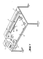
- the device shown in Fig. 1 comprises a measuring table 1 and on this a measuring bridge 2 with a measuring carriage 3, four clamping blocks 4 for holding a sheet 5 to be measured, an electronic part 6 and a personal computer 7.
- the plate of the table 1 is made of wood and has a sheet steel layer under an uppermost cover layer, which allows the printed sheet 5 to be held in place by means of magnets or the like.
- the electronic part 6 is designed as a plug-in module.
- the personal computer 7 provided with an integrated screen terminal is rotatably mounted on the table. Measuring car 3, electronic part 6 and personal computer 7 are connected via lines, not shown.
- the electronic part 6 comprises a microprocessor system and interfaces for processing the supplied and the measurement and control signals generated by it.
- the processor system in the electronic part works with the personal computer 7 in the so-called master-slave mode, the personal computer having the control function and evaluating the measured and entered data, while the system in the electronic part for carrying out the measurements and Movements of the measuring carriage is responsible (see also Fig. 8).
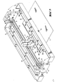
- the measuring bridge 2 is shown larger. It comprises two vertical side parts 11 and 12, which carry the other parts of the bridge, and two cover hoods 13 and 14, which cover the space between the two side parts and are pivotably mounted on them, so that they move into the position shown in FIG. 3 can be unfolded and give access to the inner parts of the measuring bridge.
- the two side parts 11 and 12 are connected to one another by a guide shaft 15 and a connecting rod 16, which is only indicated in the drawing.
- the measuring carriage 3 On the guide shaft 15, the measuring carriage, designated as a whole by 3, can be moved back and forth and pivoted about the shaft.
- the measuring carriage 3 consists of a guide block 17 provided with two ball bushings and two measuring heads 18 and 19 fastened to it and a guide or hold-down plate 20 which is angled upwards on both sides.
- the measuring carriage is provided with rollers 21 and two spring-loaded hold-down clamps 22 (FIG . 4 and 5). In operation, the measuring carriage is supported with its rollers 21 on the printed sheet 5 to be measured, whereby the distance between the measuring heads 18 and 19 and the individual fields MF of the measuring strip MS located on the printed sheet 5 is always constant.
- the measuring heads are in principle of the type described in US-A-4078858, wherein the measuring head 19 measures three color channels simultaneously, while the other measuring head 18 is only designed as a single channel, but is instead equipped with filters that can be changed manually or, if necessary, under program control.
- the measuring head 18 is intended for special cases for measuring house and spot colors, but in the normal case, as will be explained further below, the simultaneous measuring head 19 is always used.
- a toothed belt 23 is provided, which is guided over two rollers or rollers 24 and 25 rotatably mounted on each of the side parts 11 and 12 and on whose lower run the guide block 17 is fastened.
- the left-hand roller 25 in FIG. 3 is driven by a stepping motor 27 via a toothed belt reduction gear 26, which is only indicated by broken lines.
- the other roller 24 is freely rotatable in a clamping device 28.
- Stepper motor 27 and gear 26 are dimensioned such that the toothed belt 23 and thus the measuring carriage 3 are transported further by 0.1 mm per complete motor step.
- a guide profile 29 is arranged in the rear cover 13, in which the electrical flat conductor connection, not shown, of the measuring carriage 3 with the electronic part 6 runs.
- On the side parts 11 and 12 are also indicated by blocks 30 quick-release fasteners for fixing the two covers 13 and 14 in the folded-up closed position and a fork light barrier 31 each, which with a sheet metal strip, not shown, or the like. on the guide block 17 or measuring carriage 3 cooperates in such a way that the measuring carriage is automatically stopped when it hits one or the other side part, e.g. B. comes closer than a certain minimum distance due to a control error.
- a cross-sectionally U-shaped holder 32 is fastened in the front cover 14, in which five marker lamps 33 are arranged which are distributed uniformly over the length of the measuring bridge.
- These lamps each consist of a light source in the form of a so-called line lamp 33a in the outside Leg of the bracket, and P rojekomsoptik 33b in the lower support leg and generate aur the print sheet 5 in a five line lying marking lines of light 34, each about 20 mm in length.
- the beam paths of the lamps 33 are indicated in FIG. 2 by the dashed lines 34a.
- the light lines serve to align the printed sheet 5 such that the measuring strip MS comes to lie exactly below the path of movement of the two measuring heads 18 and 19.
- the projection optics 33b are mounted eccentrically and rotatably arranged in the holder. Instead of the lines of light, light spots or crosses or the like can of course also be provided as markings.
- a switching rocker 35 is provided on the top of the front cover 14, by means of which the measuring carriage 3 can be moved manually controlled into the desired measuring position along the measuring strip MS.
- the hold-down plate 20 is provided with a sighting window 36 (FIG. 5), the contour of which forms a pointer 37, which is in fixed spatial association with the optical axes of the two measuring heads 18 and 19, designated 38 and 39 stands.
- FIGS. 9 and 10 The structure of the magnetic terminal blocks 4 is shown in FIGS. 9 and 10.
- Each block 4 comprises two arch stops 4a.
- the armature 4b of a hold-down magnet 4c is arranged between them and can be pivoted about a horizontal axis 4d.
- a vertical pin 4e is slidably mounted, which is mechanically coupled to the armature 4b and visually indicates the armature position.
- the magnet 4c When the magnet 4c is acted on with tension, it pulls the armature 4b up and at the same time presses a resilient pressing member 4f down on the armature 4b, as a result of which a possibly struck printed sheet is clamped.
- the arc clamping blocks 4 are actuated automatically via electronic part 6 before the measuring carriage 3 is set in motion.
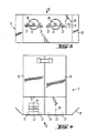
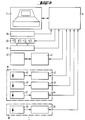
- FIG. 8 shows a basic block circuit diagram of the electrical parts of the device, insofar as it is necessary to understand how they work. It is understood that what is shown is purely exemplary and that the individual functions of the device could also be easily implemented by other implementations.
- the central part of the circuit is the personal computer 7.
- the personal computer is connected to the microprocessor system of the electronic part 6, to which the remaining electrical and electronic assemblies and parts of the device are in turn connected via lines that are not specified.
- These are the rocker 35 for manual control of the test vehicle.
- analog-digital converters are also provided on all analog-digital transitions.
- the basic apparatus structure of the device and its basic mode of operation correspond to those of the known devices of this type, for example the device shown in great detail in US Pat. No. 3,995,958: the measuring carriage 3 is operated manually or automatically guided along the measuring strip MS to be examined on the printed sheet 5, and the remission values detected by the (respectively active) measuring head 18 or 19 are processed or evaluated in electronics (here electronic part 6 and personal computer 7).
- One of the basic ideas of the method according to the invention is to divide the measuring process into two phases, namely into a so-called detection run and one or more subsequent measuring runs.
- the recognition run carried out first in time, the color measuring strips, which are initially unknown to the device, are scanned in short successive intervals and the structure of the measuring strip and the most suitable measuring positions in the strip are determined from the sample values obtained in the process.
- the color densities at the measurement positions determined during the recognition run are measured on any number of printed sheets with the same color measurement strips and are used for evaluation. With the first printed sheet, the measurement run can of course also be carried out together with the recognition run.
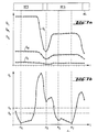
- FIG. 6a shows a section of a typical density curve as it arises when a measuring strip MS is scanned periodically during the recognition run, the increments of indexing of the measuring carriage or measuring head indexed with i being plotted along the measuring strip MS on the abscissa.
- the three curves D M , Dy and D c show the course of the simultaneously measured density values DM "Dy.
- D co for the three colors magenta, yellow and cyan in the individual sampling points i for the measuring fields of the measuring strip section MS designated here with MF1 to MF4 .
- the density profiles within the individual measuring fields MF have more or less pronounced flat areas, while they have relatively steep flanks at the transitions between the individual measuring fields.
- the centers of these flat spots are obviously possible measuring positions for the measuring runs.
- the analysis of the measuring strip structure during the recognition run is now based on the determination of these flat points of the density profiles in accordance with the second essential basic idea of the invention.
- the correct measuring positions are selected from all the flat points, which are still to be described, and thus, in principle, possible measuring positions by taking into account a predetermined minimum measuring field length and preventing multiple measuring positions from being assigned to longer measuring fields.
- the qualitative type (color, grid type, etc.) of the measuring fields can be followed.
- the unknown measuring strip is divided into overlapping intervals of the same length, with a new interval j consisting of n sampling points beginning at each sampling point i.
- the length (n-1) times the distance between two sampling points i of the intervals j preferably corresponds approximately to the difference between the minimum field length possible by the measuring optics and the diameter of the measuring spot of the measuring head.
- the standard deviations in each interval or the sum of the absolute values of the deviations of the density measured values from the mean density value in each interval are now formed.
- the three standard deviations or absolute value sums are summed in the three colors for each interval or the maximum standard deviation or absolute value sum is selected for each interval. The value found in this way is designated Xj.
- 7b shows e.g. B. that relative minima of the X j course even with gaps between two measuring fields -here z. B. between the designated with MF 5 and MF 6 - or occur in very narrow, only for visual control fields or that within a single measuring field - here MF 6- z. B. several minima may occur as a result of inhomogeneities.
- the type of measuring strip to be analyzed is known to the device or if the measuring strip to be recognized is composed of individual pieces of known measuring strip types, known correlation or comparison methods can be used for the fully automatic type determination.
- the device If the measuring strip is unknown, the device must be given certain information about the types of measuring field occurring before the recognition run. The device then tries to determine the geometric structure of the strip and the types of all measurement fields during the recognition run. Measuring fields that are not recognized or cannot be determined must then be defined or specified by hand.
- a semi-automatic measurement field determination would be e.g. B. also possible by entering the density setpoints with corresponding tolerances for all occurring measuring field types before the detection run.
- the recognition run can of course also be carried out manually controlled.
- the measuring head is successively positioned manually on the individual measuring fields and at the same time the necessary information about the relevant measuring field type is entered via the keyboard.
- the density values and the measuring position are automatically determined or recorded.
- a recognition run can be dispensed with. In order to take into account any paper distortion, only the positions of the first and last measuring field are entered manually.
- the actual measuring phase takes place.
- the measuring fields or measuring field types of interest are entered (masking the measuring field strip). From these input data and the possible measurement positions obtained during the recognition run, those are then selected at which measurements are actually to be carried out (in extreme cases, of course, these can also be all measurement fields). And finally, the measuring carriage is then guided evenly over the measuring strip and the color densities in the three color channels are determined simultaneously at all points of interest.
- the measured values are processed by the electronic part 6 and then forwarded to the personal computer 7 for processing or evaluation.
- the actual processing of the measurement data itself is not the subject of the invention.
- the detection and measurement runs are not necessarily separate, i. H. must be carried out in two separate runs, but can of course also be done together.
- the actual measurement can also z. B. may also take place when the measuring carriage returns after the detection run. Since the recognition run is usually only carried out once for each color measuring strip, this question is of minor importance.
- the measuring carriage 3 is equipped with an additional measuring head 18 for special colors.
- These so-called decorative or house colors which are often used in printing technology, have a different spectral composition than the standard printing inks and consequently require specially matched measuring filters so that a sufficiently high measuring signal is achieved.
- the additional or "piggyback" measuring head 18 now makes it possible to measure standard printing inks and special printing inks with the same precision.
- the computer is advised in the start dialog which color field (color) should be measured with which filter.
- the selection of the corresponding filter is then computer-controlled, as is the switchover from the normal simultaneous measuring head 19 to the additional measuring head 18 and vice versa.
- EAN codes European article numbering
- EAN codes have certain requirements that are set out in standards.
- the bar codes themselves and / or test marks specified in standards are suitable for checking the codes.
- the testing (of the print quality) of these codes takes place today by means of hand-held test devices, in which a laser is guided over the test marks or over the EAN code.
- the measuring processes for code checking and color measuring strips are carried out independently and take a lot of time.
- the additional measuring head 18 is now designed as a barcode reader, whereby it can possibly be articulated and / or telescopically connected to the simultaneous measuring head 19, so that it can easily be set to EAN codes present in the image of the printed sheet .
- the analysis of the EAN check marks contained in the print control strip is carried out analogously to the measuring fields of the color measuring strip, i. H. the position of the measuring positions is determined in a recognition or positioning run and the actual density measurement is then carried out in a separate measuring run, for which the same applies as what was said for the evaluation of the color measuring strip.
- the scanning of color measuring strips and EAN test marks can of course be carried out simultaneously or at different times. The actual checking of the code then takes place in the computer and is not the subject of the present application.
Abstract
Description
Die Erfindung betrifft ein Verfahren zur farbmetrischen Analyse eines auf einem Druckträger aufgebrachten Farbmessstreifens gemäss dem Oberbegriff des Patentanspruchs 1 sowie ein Densitometer zur Durchführung einer farbmetrischen Analyse gemäß dem Oberbegriff des Anspruchs 10.The invention relates to a method for colorimetric analysis of a color measuring strip applied to a print carrier according to the preamble of
Densitometer der zur Rede stehenden Art finden insbesondere im Druckereigewerbe breite Anwendung. Sie ermöglichen dem' Drucker anhand einer farbmetrischen Analyse eines mitgedruckten Farbmessstreifens und Vergleichs der dabei gefundenen Messwerte mit Sollwerten eine objektive Beurteilung der Qualität des Druckerzeugnisses sowie die entsprechende Einstellung bzw. Nachregulierung der Druckeinrichtung im Hinblick auf ein gewünschtes Ergebnis. Näheres darüber findet sich in der einschlägigen Fachliteratur, insbesondere auch in US-A-4 200 932 und US-A-3 995 958 und den darin angeführten Druckschriften.Densitometers of the type in question are widely used particularly in the printing industry. They enable the printer to carry out an objective assessment of the quality of the printed product and the appropriate adjustment or readjustment of the printing device with regard to a desired result on the basis of a colorimetric analysis of a color measuring strip that is also printed and a comparison of the measured values found with target values. More details can be found in the relevant technical literature, in particular also in US-A-4,200,932 and US-A-3,995,958 and the publications cited therein.
Aus naheliegenden Gründen ist es erstrebenswert, die Ausmessung und Auswertung der Farbmessstreifen so weit wie möglich zu automatisieren. Dementsprechend sind auch schon verschiedene sogenannte Abtast- oder Scanning-Densitometer bekanntgeworden, die mit einem auf einer den Druckbogen überspannenden Brücke hin- und herbeweglichen Messkopf und einer entsprechenden Steuerung ausgestattet sind und den Messstreifen mehr oder weniger selbsttätig abzutasten und auszumessen vermögen.For obvious reasons, it is desirable to automate the measurement and evaluation of the color measuring strips as much as possible. Accordingly, various so-called scanning densitometers have already become known, which are equipped with a measuring head which moves back and forth on a bridge spanning the printed sheet and a corresponding control and which are able to scan and measure the measuring strip more or less automatically.
Ein grundlegendes Problem bei der automatischen Messstreifen-Ausmessung besteht in der Auffindung und Identifizierung der einzelnen Messfelder sowie in der Auffindung einer geeigneten Messposition bzw. richtigen Zuordnung der Messsignale zu den einzelnen Messfeldern. Dabei muss berücksichtigt werden, dass sich der Messkopf bzw. die ihn steuernde Elektronik einzig und allein an der im Messstreifen enthaltenen Information selbst orientieren kann, wenn von dem ungebräuchlichen und in der Regel unerwünschten Sonderfall abgesehen wird, dass zusätzliche Hilfsmittel wie Synchronisierzeichen oder ähnliches verwendet werden (siehe z. B. EP-A-11376), deren Positionen in einem Erkennungslauf vom Messkopf festgestellt werden und die dann für anschließende Abtastungen gespeichert werden.A fundamental problem with automatic measuring strip measurement is to find and identify the individual measuring fields as well as to find a suitable measuring position or to correctly assign the measuring signals to the individual measuring fields. It must be taken into account that the measuring head or the electronics controlling it can only orient itself on the information contained in the measuring strip itself, if apart from the unusual and usually undesirable special case that additional aids such as synchronization characters or the like are used (see e.g. EP-A-11376), the positions of which are determined by the measuring head in a detection run and which are then stored for subsequent scans.
- Bei dem in der DE-A-2 901 980 beschriebenen Abtast-Densitometer wird dieses Problem angegangen. indem der Messstreifen kontinuierlich abgetastet und das dabei erzeugte Messsignal zweimal differenziert wird. Durch das zweimalige Differenzieren entstehen an den Messfeldgrenzen Nulldurchgänge des Signals. Als Messfeldmitte und geeigneter Messort wird nun derjenige Ort definiert, der in einem bestimmten, vorgegebenen Abstand auf einen Nulldurchgang und damit auf eine Messfeldgrenze folgt. Zur einfachen Korrektur der bei dieser Vorgehensweise auftretenden Aperturfehler werden durch der Struktur des zu messenden Farbmessstreifens entsprechenden Wechsel der dem Messkopf vorgeschalteten Farbfilter nur Dichtesprünge in einer Richtung für die Erkennung der Messfeldgrenzen herangezogen.This problem is addressed in the scanning densitometer described in DE-A-2 901 980. by continuously scanning the measuring strip and differentiating the measuring signal generated twice. The two differentiations result in zero crossings of the signal at the measuring field boundaries. The center of the measuring field and a suitable measuring location is now defined as the location that follows a zero crossing and thus a measuring field boundary at a specific, predetermined distance. For simple correction of the aperture errors occurring with this procedure, only changes in density in one direction are used for the detection of the measuring field boundaries due to the structure of the color measuring strip to be measured, corresponding change of the color filter upstream of the measuring head.
Bei diesem bekannten Densitometer ist die Ermittlung der Messfeldgrenzen nur gewährleistet, wenn im Farbmessstreifen Volltonfelder mit ausreichend hoher Dichte und ständig wechselnden Farben aufeinanderfolgen. Ein weiterer, noch viel schwerwiegender Nachteil besteht darin, dass dem Densitometer sowohl der Aufbau bzw. die Struktur des Messstreifens als auch die nominellen Messfeldlängen bekannt sein müssen, so dass die Farbfilter in geeigneter Weise gewechselt und die Messfeldmitten als Messpositionen bestimmt werden können.With this known densitometer, the determination of the measuring field limits is only guaranteed if solid color fields with a sufficiently high density and constantly changing colors follow one another in the color measuring strip. Another, much more serious disadvantage is that the densitometer must know both the structure of the measuring strip and the nominal measuring field lengths, so that the color filters can be changed in a suitable manner and the measuring field centers can be determined as measuring positions.
In der US-A-3 995 958 ist ein anderes bis zu einem gewissen Grad automatisch arbeitendes Abtast-Densitometer beschrieben. Dieses Densitometer tastet den Messstreifen in diskreten Schritten ab, wobei die Feststellung einer Farbdichte-Messwertänderung bestimmten Ausmasses bei zwei aufeinanderfolgenden Abtastschritten zur Anzeige eines Uebergangs zwischen zwei Messstreifenblöcken mit unterschiedlichen Farbeigenschaften ausgenutzt wird. Als massgeblicher Farbdichte-Messwert für einen Block wird der Messwert an derjenigen Stelle ausgewählt, die einen bestimmten Abstand von der nach dem genannten Kriterium ermittelten Uebergangsstelle hat. Nach jedem Blockübergang wird eine Wechsel des Farbfilters durchgeführt, um für den nächstfolgenden Blockübergang einen ausreichend grossen Dichtesprung sicherzüstellen.US-A-3 995 958 describes another, to a certain extent, automatic sensing densitometer. This densitometer scans the measuring strip in discrete steps, the determination of a change in the color density measured value being used in two successive scanning steps to indicate a transition between two measuring strip blocks with different color properties. As the relevant color density measurement value for a block, the measurement value is selected at the point which is at a certain distance from the transition point determined according to the criterion mentioned. After each block transition, the color filter is changed to ensure a sufficiently large density jump for the next block transition.
Der Nachteil dieses bekannten Densitometers besteht darin, dass es einen ganz bestimmten Aufbau des Farbmessstreifens voraussetzt, nämlich eine zyklische Folge von sich gegenseitig überlappenden Vollton-Blöcken oder Leerblöcken. Ferner muss die Farbreihenfolge der einzelnen Blöcke dem Densitometer bzw. dessen Steuerung bekannt sein. Desgleichen müssen auch die Längen der einzelnen Blöcke bekannt sein, um die effektiven Messorte aufgrund der relativ ungenau ermittelten Blockübergänge zu bestimmen.The disadvantage of this known densitometer is that it requires a very specific structure of the color measuring strip, namely a cyclic sequence of mutually overlapping full-tone blocks or empty blocks. Furthermore, the color sequence of the individual blocks must be known to the densitometer or its control. Likewise, the lengths of the individual blocks must also be known in order to determine the effective measuring locations on the basis of the relatively inaccurately determined block transitions.
Durch die vorliegende Erfindung sollen nun diese Nachteile vermieden und ein Verfahren und eine Vorrichtung der zur Rede stehenden Art derart verbessert werden. dass eine weitestgehende vollautomatische Abtastung beliebiger Farbmessstreifen ermöglicht wird, und zwar unabhjängig vom Aufbau des Messstreifens und ohne dass dessen Struktur im voraus bekannt sein muss. Insbesondere sollen für die automatische Abtastung keine Synchronisiermarken oder dergleichen und ferner auch keine Filterwechsei nötig sein.These disadvantages are to be avoided by the present invention and a method and a device of the type in question are to be improved in this way. that a largely fully automatic scanning of any color measuring strips is made possible, regardless of the structure of the measuring strip and without having to know its structure beforehand. In particular, no synchronization marks or the like and furthermore no filter change should be necessary for the automatic scanning.
Das diesen Anforderungen gerecht werdende Verfahren und das entsprechende Densitometer sWU, erfindungsgemäss durch die in den unabhängigen Ansprüchen beschriebenen Massnahmen und Merkmale gekennzeichnet. Vorteilhafte Ausgestaltungen sind in den abhängigen Ansprüchen beschrieben.The process that meets these requirements and the corresponding densitometer s W U, according to the invention characterized by the measures and features described in the independent claims. Advantageous embodiments are described in the dependent claims.
Im folgenden wird die Erfindung anhand der Zeichnung näher erläutert.The invention is explained in more detail below with reference to the drawing.
Es zeigen :
Figur 1 eine etwas vereinfachte Gesamtansicht eines Ausführungsbeispiels einer erfindungsgemässen Vorrichtung,Figur 2 eine teilweise aufgeschnittene Ansicht der Messbrücke aus Fig. 1,Figur 3 die Messbrücke aus Fig. 2 in teilweise demontiertem bzw. geöffnetem Zustand,Figur 4 eine Vorderansicht des Messkopfs aus Fig. 3,Figur 5 eine Unteransicht desselben Messkopfs,Figuren 6 und 7 Diagramme zur Erläuterung des erfindungsgemässen Verfahrens.Figur 8 ein grundsätzliches Blockschaltbild des elektrischen Teils der Vorrichtung, und- Figuren 9 und 10. einen Vertikalschnitt und eine Unteransicht eines Klemmblocks.
- FIG. 1 shows a somewhat simplified overall view of an exemplary embodiment of a device according to the invention,
- FIG. 2 shows a partially cutaway view of the measuring bridge from FIG. 1,
- FIG. 3 shows the measuring bridge from FIG. 2 in a partially disassembled or opened state,
- FIG. 4 shows a front view of the measuring head from FIG. 3,
- FIG. 5 shows a bottom view of the same measuring head,
- Figures 6 and 7 diagrams to explain the inventive method.
- Figure 8 is a basic block diagram of the electrical part of the device, and
- Figures 9 and 10. a vertical section and a bottom view of a terminal block.
Die in Fig. 1 dargestellte Vorrichtung umfasst einen Messtisch 1 und auf diesem eine Messbrücke 2 mit einem Messwagen 3, vier Klemmblöcke 4 zum Festhalten eines auszumessenden Druckbogens 5, einen Elektronikteil 6 und einen Personal-Computer 7. Die Platte des Tischs 1 besteht aus Holz und weist unter einer obersten Deckschicht eine Stahlblechschicht auf, die es erlaubt, den Druckbogen 5 mittels Magneten oder dergleichen festzuhalten. Der Elektronikteil 6 ist als Einschubmodul ausgeführt. Der mit einem integrierten Bildschirm-Terminal versehene Personal-Computer 7 ist drehbar auf dem Tisch befestigt. Messwagen 3, Elektronikteil 6 und Personal-Computer 7 sind über nicht gezeigte Leitungen verbunden.The device shown in Fig. 1 comprises a measuring table 1 and on this a
Der Elektronikteil 6 umfasst ein Mikroprozessorsystem und Schnittstellen zur Aufbereitung der ihm zugeführten sowie der von ihm erzeugten Mess- und Steuersignale. Das Prozessorsystem im Elektronikteil arbeitet mit dem Personal-Computer 7 im sogenannten Master-Slave-Betrieb zusammen, wobei der Personal-Computer die Kontrollfunktion hat und die Auswertung der gemessenen und eingegebenen Daten vornimmt, während das System im Elektronikteil für die Ausführung der Messungen und der Bewegungen des Messwagens zuständig ist (siehe auch Fig.8).The
In den Fig. 2 und 3 ist die Messbrücke 2 grösser dargestellt. Sie umfasst zwei vertikale Seitenteile 11 und 12, die die übrigen Teile der Brücke tragen, sowie zwei Abdeckhauben 13 und 14, die den Zwischenraum zwischen den beiden Seitenteilen überdachen und an diesen schwenkbar gelagert sind, so dass sie in die in Fig. 3 dargestellte Lage auseinandergeklappt werden können und den Zugang zu den inneren Teilen der Messbrücke freigeben. Die beiden Seitenteile 11 und 12 sind durch eine Führungswelle 15 und eine nur andeutungsweise dargestellte Verbindungsstange 16 miteinander verbunden.2 and 3, the
Auf der Führungswelle 15 ist der als Ganzes mit 3 bezeichnete Messwagen hin- und herbeweglich sowie um die Welle schwenkbar geführt. Der Messwagen 3 besteht aus einem mit zwei Kugelbüchsen versehenen Führungsblock 17 und zwei an diesem befestigten Messköpfen 18 und 19 sowie einem beidseits nach oben abgewinkelten Leit- oder Niederhalteblech 20. An der Unterseite ist der Messwagen mit Rollen 21 sowie zwei gefederten Niederhaltebügeln 22 versehen (Fig. 4 und 5). Im Betrieb stützt sich der Messwagen mit seinen Rollen 21 auf dem auszumessenden Druckbogen 5 ab, wodurch der Abstand zwischen den Messköpfen 18 und 19 und den einzelnen Feldern MF des am Druckbogen 5 befindlichen Messstreifens MS stets konstant ist. Die Messköpfe sind im Prinzip von der in der US-A-4078858 beschriebenen Art, wobei der Messkopf 19 simultan drei Farbkanäle misst, während der andere Messkopf 18 nur einkanalig ausgelegt, dafür aber mit manuell oder gegebenenfalls programmgesteuert wechselbaren Filtern ausgestattet ist. Der Messkopf 18 ist für Sonderfälle zur Messung von Haus- und Schmuckfarben bestimmt, im Normalfall wird jedoch, wie weiter unten noch erläutert wird, stets der Simultanmesskopf 19 verwendet.On the
Zum Antrieb des Messwagens 3 ist ein Zahnriemen 23 vorgesehen, der über zwei an je einem der Seitenteile 11 und 12 drehbar gelagerte Rollen oder Walzen 24 und 25 geführt und an dessen unterem Trum der Führungsblock 17 befestigt ist. Die in der Fig. 3 linke Walze 25 ist über ein nur strichliert angedeutetes Zahnriemen-Untersetzungsgetriebe 26 von einem Schrittmotor 27 angetrieben. Die andere Walze 24 ist in einer Spannvorrichtung 28 frei drehbar gelagert. Schrittmotor 27 und Getriebe 26 sind so bemessen, dass der Zahnriemen 23 und damit der Messwagen 3 pro vollständigem Motor-Schritt um 0,1 mm weitertransportiert wird.To drive the measuring
In der hinteren Abdeckhaube 13 ist ein Führungsprofil 29 angeordnet, in welchem die nicht dargestellte elektrische Flachleiter-Verbindung des Messwagens 3 mit dem Elektronikteil 6 verläuft. An den Seitenteilen 11 und 12 sind ferner noch durch Blöcke 30 angedeutete Schnellverschlüsse zum Fixieren der beiden Abdeckhauben 13 und 14 in der hochgeklappten geschlossenen Stellung sowie je eine Gabellichtschranke 31 angeordnet, welche mit einem nicht dargestellten Blechstreifen o.ä. am Führungsblock 17 bzw. Messwagen 3 derart zusammenwirkt, dass der Messwagen automatisch angehalten wird, wenn er dem einen oder dem anderen Seitenteil z. B. infolge eines Steuerungsfehlers näher als eine bestimmte Mindestdistanz kommt.A
In der vorderen Abdeckhaube 14 ist eine im Querschnitt U-förmige Halterung 32 befestigt, in welcher fünf gleichmässig über die Länge der Messbrücke verteilte Markierungslampen 33 angeordnet sind. Diese Lampen bestehen je aus einer Lichtquelle in Form einer sogenannten Strichlampe 33a im.eßeren Schenkel der Halterung und einer Projektionsoptik 33b im unteren Halterungsschenkel und erzeugen aur dem Druckbogen 5 fünf in einer Linie liegende Markierungslichtstriche 34 von je etwa 20 mm Länge. Die Strahlengänge der Lampen 33 sind in der Fig. 2 durch die strichlierten Linien 34a angedeutet. Die Lichtstriche dienen zur Ausrichtung des Druckbogens 5 derart, dass der Messstreifen MS exakt unter der Bewegungsbahn der beiden Messköpfe 18 und 19 zu liegen kommt. Zur genauen Justierung der Lichtstriche selbst sind die Projektionsoptiken 33b exzentrisch gefasst und drehbar in der Halterung angeordnet. Anstelle der Lichtstriche können als Markierungen selbstverständlich auch Lichtpunkte oder Kreuze oder dergleichen vorgesehen sein.A cross-sectionally
Schliesslich ist auf der Oberseite der vorderen Abdeckung 14 noch eine Schaltwippe 35 vorgesehen, mittels welcher der Messwagen 3 manuell gesteuert in die gewünschte Messposition längs des Messstreifens MS gefahren werden kann. Zur Erleichterung dieser manuellen Positionierung ist das Niederhalteblech 20 mit einem Visier-Fenster 36 (Fig. 5) versehen, dessen Kontur einen Zeiger 37 bildet, der in fester räumlicher Zuordnung zu den .mit 38 und 39 bezeichneten optischen Achsen der beiden Messköpfe 18 und 19 steht.Finally, a switching
Der Aufbau der Magnet-Klemmblöcke 4 geht aus den Fig. 9 und 10 hervor. Jeder Block 4 umfasst zwei Bogenanschläge 4a. Zwischen diesen ist der Anker 4b eines Niederhaltemagneten 4c angeordnet und um eine horizontale Achse 4d schwenkbar. Im hinteren Blockteil ist noch ein vertikaler Stift 4e verschiebbar gelagert, welcher mit dem Anker 4b mechanisch gekoppelt ist und die Ankerstelung optisch anzeigt. Bei Beaufschlagung des Magneten 4c mit Spannung zieht er den Anker 4b hoch und drückt damit gleichzeitig ein federndes Anpressglied 4f am Anker 4b nach unten, wodurch ein allenfalls angeschlagener Druckbogen festgeklemmt wird. Die Betätigung der Bogenklemmblöcke 4 erfolgt via Elektronikteil 6 automatisch, bevor der Messwagen 3 in Bewegung gesetzt wird.The structure of the magnetic terminal blocks 4 is shown in FIGS. 9 and 10. Each
Die elektrischen Verbindungsleitungen der einzelnen Teile der Messbrücke untereinander und mit dem Elektronikteil sind in der Zeichnung der Uebersichtlichkeit halber nicht dargestellt.The electrical connection lines of the individual parts of the measuring bridge with each other and with the electronic part are not shown in the drawing for the sake of clarity.
In Fig. 8 ist ein prinzipielles Blockschaltschema der elektrischen Teile der Vorrichtung, soweit es zum Verständnis von deren Funktionsweise nötig ist, dargestellt. Es versteht sich, dass das Dargestellte rein beispielsweisen Charakter besitzt und die einzelnen Funktionen der Vorrichtung ohne weiteres auch durch andere Implementationen realisiert werden könnten.FIG. 8 shows a basic block circuit diagram of the electrical parts of the device, insofar as it is necessary to understand how they work. It is understood that what is shown is purely exemplary and that the individual functions of the device could also be easily implemented by other implementations.
Der zentrale Teil der Schaltung ist, wie schon erwähnt wurde, der Personal-Computer 7. Dabei kann es sich im Prinzip um jeden beliebigen Klein- oder Mikrocomputer handeln. Der Personal-Computer steht mit dem Mikroprozessorsystem des Elektronikteils 6 in Verbindung, an welches wiederum über nicht näher bezeichnete Leitungen die übrigen elektrischen und elektronischen Baugruppen und -teile der Vorrichtung angeschlossen sind. Es sind dies die Wippe 35 zum manuellen Steuern des Messwagens. die hier in ihrer Gesamtheit mit 40 bezeichneten vier Magnet-Klemmblöcke 4 zum Niederhalten des Druckbogens auf dem Messtisch, die Lichtschranken 31 zur Begrenzung der Messwagenbewegung, eine Schnittstelle 41 zur Steuereung des Schrittmotors 27, drei Messverstärker 42-44 für die drei Fotosensoren 45-47 im Simultanmesskopf 19 und ein Messverstärker 48 für den Fotosensor 49 im Spezial- oder Zusatzmesskopf 18. Ferner sind noch an allen Analog-Digital-Uebergängen nicht gesondert dargestellte Analog-Digitalwandler vorgesehen.As already mentioned, the central part of the circuit is the personal computer 7. In principle, this can be any small or microcomputer. The personal computer is connected to the microprocessor system of the
Nach dem Vorstehenden stimmen somit der grundsätzliche apparative Aufbau der Vorrichtung und ihre grundsätzliche Funktionsweise mit denen der bekannten Vorrichtungen dieser Art, beispielsweise etwa der in der US-A-3 995 958 in grösster Ausführlichkeit dargestellten Vorrichtung überein : Der Messwagen 3 wird von Hand oder automatisch dem zu untersuchenden Messstreifen MS auf dem Druckbogen 5 entlanggeführt, und die dabei vom (jeweils aktiven) Messkopf 18 oder 19 erfassten Remissionswerte werden in einer Elektronik (hier Elektronikteil 6 und Personal-Computer 7) verarbeitet bzw. ausgewertet.According to the above, the basic apparatus structure of the device and its basic mode of operation correspond to those of the known devices of this type, for example the device shown in great detail in US Pat. No. 3,995,958: the measuring
Im folgenden wird die Arbeitsweise der Vorrichtung bzw. das erfindungsgemässe Messverfahren und die Unterschiede zu der eben genannten bekannten Vorrichtung näher erläutert.The mode of operation of the device and the measurement method according to the invention and the differences from the known device just mentioned are explained in more detail below.
Eine der grundlegenden Ideen des erfindungsgemässen Verfahrens besteht darin den Messvorgang in zwei Phasen aufzuteilen, und zwar in einen sogenannten Erkennungslauf und einen oder mehrere darauf folgende Messläufe. Im zeitlich als erstes durchgeführten Erkennungslauf werden der der Vorrichtung zunächst unbekannte Farbmessstreifen in kurz aufeinanderfolgenden Abständen abgetastet und aus den dabei gewonnenen Abtastwerten der Aufbau des Messstreifens sowie die geeignetsten Messpositionen im Streifen ermittelt. In den folgenden Messläufen werden nun die Farbdichten an den während dem Erkennungslauf bestimmten Messpositionen auf beliebig vielen Druckbogen mit gleichen Farbmessstreifen gemessen und der Auswertung zugeführt. Beim ersten Druckbogen kann der Messlauf natürlich auch zusammen mit dem Erkennungslauf durchgeführt werden.One of the basic ideas of the method according to the invention is to divide the measuring process into two phases, namely into a so-called detection run and one or more subsequent measuring runs. In the recognition run carried out first in time, the color measuring strips, which are initially unknown to the device, are scanned in short successive intervals and the structure of the measuring strip and the most suitable measuring positions in the strip are determined from the sample values obtained in the process. In the following measurement runs, the color densities at the measurement positions determined during the recognition run are measured on any number of printed sheets with the same color measurement strips and are used for evaluation. With the first printed sheet, the measurement run can of course also be carried out together with the recognition run.
Im nachstehenden Fliessschema ist dieses erfindungsgemässe Arbeitsprinzip nochmals übersichtlich dargestellt. ,
(Siehe das Schema, Seite 5 f.)
(See the diagram, page 5 f.)
In Fig. 6a ist ein Ausschnitt aus einem typischen Dichteverlauf dargestellt, wie er beim periodischen Abtasten eines Messstreifens MS während des Erkennungslaufs entsteht, wobei auf der Abszisse die mit i indexierten Vorschubinkremente des Messwagens bzw. Messkopfs längs des Messstreifens MS aufgetragen sind. Die drei Kurven DM, Dy und Dc zeigen den Verlauf der simultan gemessenen Dichtewerte DM" Dy. und Dco für die drei Farben Magenta, Gelb und Cyan in den einzelnen Abtastpunkten i für die hier mit MF1 bis MF4 bezeichneten Messfelder des Messstreifenausschnitts MS.FIG. 6a shows a section of a typical density curve as it arises when a measuring strip MS is scanned periodically during the recognition run, the increments of indexing of the measuring carriage or measuring head indexed with i being plotted along the measuring strip MS on the abscissa. The three curves D M , Dy and D c show the course of the simultaneously measured density values DM "Dy. And D co for the three colors magenta, yellow and cyan in the individual sampling points i for the measuring fields of the measuring strip section MS designated here with MF1 to MF4 .
Wie man erkennt, besitzen die Dichteverläufe innerhalb der einzelnen Messfelder MF mehr oder weniger .ausgeprägte Flachstellen, während sie an den Uebergängen zwischen den einzelnen Messfeldern relativ steile Flanken aufweisen. Die Mitten dieser Flachstellen sind offenschtlich mögliche Messpositionen für die Messläufe. Die Analyse des Messstreifenaufbaus während des Erkennungslaufs beruht nun gemäss dem zweiten wesentlichen Grundgedanken der Erfindung auf der Ermittlung dieser Flachstellen der Dichteverläufe. Dabei werden aus allen in noch zu beschreibender Weise ermittelten Flachstellen und damit im Prinzip möglichen Messpositionen die richtigen Messpositionen dadurch ausgewählt, dass ausserdem noch eine vorgegebene minimale Messfeldlänge berücksichtigt und verhindert wird, dass auf längere Messfelder mehrere Messpositionen entfallen. Nach dieser Analyse des geometrischen Aufbaus des Messstreifens können sich noch den qualitativen Typus (Farbe, Rasterart etc.) der Messfelder betreffende Analysen anschliessen.As can be seen, the density profiles within the individual measuring fields MF have more or less pronounced flat areas, while they have relatively steep flanks at the transitions between the individual measuring fields. The centers of these flat spots are obviously possible measuring positions for the measuring runs. The analysis of the measuring strip structure during the recognition run is now based on the determination of these flat points of the density profiles in accordance with the second essential basic idea of the invention. The correct measuring positions are selected from all the flat points, which are still to be described, and thus, in principle, possible measuring positions by taking into account a predetermined minimum measuring field length and preventing multiple measuring positions from being assigned to longer measuring fields. After this analysis of the geometric structure of the measuring strip, the qualitative type (color, grid type, etc.) of the measuring fields can be followed.
Zur Erkenung der Flachstellen wird der unbekannte Messstreifen in überlappende Intervalle gleicher Länge unterteilt, wobei bei jedem Abtastpunkt i ein aus n Abtastpunkten bestehendes neues Intervall j beginnt. Die Länge (n-1) mal Abstand zwischen zwei Abtastpunkten i der Intervalle j entspricht dabei vorzugsweise etwa der Differenz zwischen der durch die Messoptik minimal möglichen Messfeidlänge und dem Durchmesser des Messflecks des Messkopfs.To identify the flat spots, the unknown measuring strip is divided into overlapping intervals of the same length, with a new interval j consisting of n sampling points beginning at each sampling point i. The length (n-1) times the distance between two sampling points i of the intervals j preferably corresponds approximately to the difference between the minimum field length possible by the measuring optics and the diameter of the measuring spot of the measuring head.
Es werden nun für jede der drei Farben einzeln die Standardabweichungen in jedem Intervall oder die Summe der Absolutwerte der Abweichungen der Dichtmesswerte vom Dichtemittelwert in jedem Intervall gebildet. Jetzt werden die drei Standardabweichungen bzw. Absolutwertsummen in den drei Farben für jedes Intervall summiert oder es wird für jedes Intervall die maximale Standardabweichung bzw. Absolutwertsumme ausgewählt. Der so gefundene Wert sei mit Xj bezeichnet.For each of the three colors, the standard deviations in each interval or the sum of the absolute values of the deviations of the density measured values from the mean density value in each interval are now formed. Now the three standard deviations or absolute value sums are summed in the three colors for each interval or the maximum standard deviation or absolute value sum is selected for each interval. The value found in this way is designated Xj.
Mathematisch lassen sich diese Operationen etwa wie folgt formulieren :
- Intervalleinteilung :
- Intervall j = Abtastpunkte j bis j + n - 1
- 1 ≦j≦imax-
n+ 1 - n = Anzahl Abtastpunkte pro Intervall, imax = max. Abtastschrittzahl.
- Interval division:
- Interval j = sampling points j to j + n - 1
- 1 ≦ j ≦ i max -
n + 1 - n = number of sampling points per interval, i max = max. Number of sampling steps.
Dichtemittelwerte in den drei Farben in jedem Intervall j :![]()
![]()
![]()
![]()
![]()
![]()
Bildung der Summe der Absolutwerte der Abweichungen der Dichtemesswerte vom Dichtemittelwert des zugehörigen Intervalls für jeden Farbkanal in jedem Intervall :![]()
![]()
![]()
![]()
![]()
![]()
Bildung der empirischen Standardabweichung in jedem Intervall für jeden Dichteverlauf einzeln :![]()
![]()

![]()
![]()
Bestimmung des Maximalwerts aus ACl, AMi, Ay, oder SCl, SMi, SYj in jedem Intervall :
- Ajmax = max (Ac, AM1, AYl)
bzw.
- Sjmax = max (SCi, SMi, Sy,)
oder
- Bildung der Summe von ACl, AMi, AYi bzw. SG, SMi., Sy, in jedem Intervall :


- Auswahl einer der Werte Ajmax1 Sjmax1,

- A j max = max (A c , A M1 , A Yl )
respectively.
- S j max = max (S Ci , S Mi , Sy,)
or
- Formation of the sum of A Cl , A Mi , A Yi or S G , S Mi. , Sy, in each interval:
- Selection of one of the values A j max 1 S j max 1 ,
Trägt man die Werte Xj gemäss Fig. 6b auf, so stellt man fest, dass der Xj-Verlauf unabhängig von der getroffenen Wahl im Bereich der Flachstellen der Dichteverläufe relative Minima aufweist. Umgekehrt kann daher geschlossen werden, dass die Mitten derjenigen Intervalle, für welche der Xj-Verlauf relative Minima aufweist, als mögliche Messpositionen in Frage kommen. In Fig. 6b sind solche möglichen Messpositionen mit m, bis m3 bezeichnet.If the values X j according to FIG. 6 b are plotted, it is found that the X j curve has relative minima regardless of the choice made in the area of the flat points of the density curves. Conversely, it can therefore be concluded that the centers of those intervals for which the X j course has relative minima can be considered as possible measurement positions. 6b, such possible measurement positions are designated by m, to m 3 .
Wie schon weiter vorne erwähnt, sind von diesen möglichen Messpositionen nicht tatsächlich alle als effektive Messpositionen brauchbar. Die Fig. 7b zeigt z. B., dass relative Minima des Xj-Verlaufs auch bei Zwischenräumen zwischen zwei Messfeldern -hier z. B. zwischen den mit MF 5 und MF 6 bezeichneten-oder bei ganz schmalen, nur für visuelle Kontrollen bestimmten Feldern auftreten oder dass innerhalb eines einzigen Messfeldes -hier MF 6- z. B. infolge Inhomogenitäten auch mehrere Minima auftreten können.As mentioned earlier, not all of these possible measurement positions can actually be used as effective measurement positions. 7b shows e.g. B. that relative minima of the X j course even with gaps between two measuring fields -here z. B. between the designated with
Um diese ungewollten Messpositionen bzw. Mehrdeutigkeiten ausschalten zu können, werden nun nur solche Minima berücksichtigt, deren Werte Xj einen bestimmten Schwellenwert Xa unterschreiten. Im Beispiel gemäss Fig. 7b ist dies für die Minimastellen ms, m6 und m7 der Fall, während Xj bei der Zwischenraum-Minimastelle m8 über dem Schwellenwert Xa liegt. Als Alternative können unechte Messpositionen auf zu schmalen Messfeldern bzw. Zwischenräumen auch dadurch unterdrückt werden. dass der durch die Messoptik gegebene Minimalabstand zwischen zwei Messpositionen berücksichtigt wird.In order to be able to eliminate these unwanted measurement positions or ambiguities, only those minima are taken into account whose values X j fall below a certain threshold value Xa. In the example according to FIG. 7b, this is the case for the minimum positions m s , m 6 and m 7 , while X j lies above the threshold value X a at the minimum space m 8 . As an alternative, spurious measuring positions on measuring fields or gaps that are too narrow can also be suppressed in this way. that the minimum distance between two measuring positions given by the measuring optics is taken into account.
Zur Beseitigung von Mehrfach-Messpositicnen auf ein und demselben Messfeld kann so vorgegangen werden, dass man die drei Farbdichten an aufeinanderfolgenden minimastellen miteinander vergleicht und daraus bestimmt, ob die Minimastellen auf dem gleichen Messfeld liegen oder nicht. Als Alternative kann getestet werden, ob zwischen zwei aufeinanderfolgenden Minimastellen eine Messfeldgrenze liegt. Eine solche Grenze ist dann vorhanden, wenn zwischen den beiden Minimastellen ein Intervall existiert, dessen Xi einen zweiten Schwellenwert Xb überschreitet. In Fig. 7b ist dies z. B. für das Paar me-me der Fall, während die Bedingung für das paar me-m7 nicht zutrifft. diese beiden messpositionen somit auf demselben Messfeld liegen. in diesem Fall wird man von den zwei oder mehreren Messpositionen eine auswählen, vorzugsweise diejenige mit dem kleinsten Xi.To eliminate multiple measurement positions on one and the same measuring field, one can proceed by comparing the three color densities at successive minimum positions with one another and determining whether the minimum positions lie on the same measuring field or not. As an alternative, you can test whether there is a measuring field boundary between two successive minimum positions. Such a limit is present if there is an interval between the two minimum positions, the X i of which exceeds a second threshold value X b . In Fig. 7b this is e.g. B. for the pair m e -m e the case, while the condition for the couple m e -m 7 does not apply. these two measuring positions are therefore on the same measuring field. in this case one of the two or more measuring positions will be selected, preferably the one with the smallest X i .
Mit den bisherigen Schritten des Erkennungslaufs wurde mit Ausnahme weniger spezieller Messfelder, die von der Vorrichtung nicht erkannt bzw. unterschieden werden können (z. B. aufeinanderfolgende gleichfarbige Linienrasterfelder, die sich nur durch die Richtung der Rasterlinien unterscheiden), der geometrische Aufbau eines unbekannten Farbmessstreifens ermitelt. Mit den im folgenden beschriebenen prinzipiellen Vorgehensweisen können, sofern erwünscht, auch darüber hinausgehende Informationen, wie z. B. Rasterart etc. über den Messstreifen gewonnen werden. Der Grad dieser automatischen Erkennung bzw. Analyse hängt dabei davon ab, wieviel Information der Vorrichtung über den betreffenden Messstreifen bereits bekannt ist.With the previous steps of the recognition run, with the exception of a few special measuring fields, which cannot be recognized or distinguished by the device (e.g. successive lines of the same color, which differ only in the direction of the grid lines), the geometric structure of an unknown color measuring strip became determined. With the basic procedures described below, if desired, additional information such as B. grid type etc. can be obtained via the measuring strips. The degree of this automatic detection or analysis depends on how much information of the device about the measuring strip in question is already known.
Falls der Vorrichtung der Typ des zu analysierenden Messstreifens bekant ist oder falls der zu erkennende Messstreifen aus einzelnen Stücken bekannter Messstreifen-Typen zusammengesetzt ist, können bekannte Korrelations- oder Vergleichsverfahren zur vollautomatischen Typus-Bestimmung herangezogen werden.If the type of measuring strip to be analyzed is known to the device or if the measuring strip to be recognized is composed of individual pieces of known measuring strip types, known correlation or comparison methods can be used for the fully automatic type determination.
Bei einem unbekannten Messstreifen müssen der Vorrichtung gewisse Angaben über die vorkommenden Messfeld-Typen vor dem Erkennungslauf eingegeben werden. Die Vorrichtung versucht dann während des Erkennungslaufs den geometrischen Aufbau des Streifens sowie die Typen aller Messfelder zu bestimmen. Nicht erkannte oder nicht bestimmbare Messfelder müssen dann von Hand definiert bzw. spezifiziert werden.If the measuring strip is unknown, the device must be given certain information about the types of measuring field occurring before the recognition run. The device then tries to determine the geometric structure of the strip and the types of all measurement fields during the recognition run. Measuring fields that are not recognized or cannot be determined must then be defined or specified by hand.
Eine halbautomatische Messfeld-Bestimmung wäre z. B. auch möglich, indem der Vorrichtung vor dem Erkennungslauf die Dichtesollwerte mit entsprechenden Toleranzen für alle vorkommenden Messfeldtypen eingegeben werden.A semi-automatic measurement field determination would be e.g. B. also possible by entering the density setpoints with corresponding tolerances for all occurring measuring field types before the detection run.
Grundsätzlich kann der Erkennungslauf natürlich auch manuell gesteuert durchgeführt werden. Der Messkopf wird dabei manuell sukzessive auf den einzelnen Messfeldern positioniert und gleichzeitig werden die nötigen Angaben über den betreffenden Messfeld-Typus via Tastatur eingegeben. Die Dichtewerte und die Messposition werden automatisch ermittelt bzw. festgehalten.In principle, the recognition run can of course also be carried out manually controlled. The measuring head is successively positioned manually on the individual measuring fields and at the same time the necessary information about the relevant measuring field type is entered via the keyboard. The density values and the measuring position are automatically determined or recorded.
Auch im Falle, dass der Messstreifen der Vorrichtung bekannt ist, kann auf einen Erkennungslauf verzichtet werden. Um einen allfälligen Papierverzug zu berücksichtigen, werden dabei lediglich die Positionen des ersten und des letzten Messfelds manuell eingegeben.In the event that the measuring strip of the device is known, a recognition run can be dispensed with. In order to take into account any paper distortion, only the positions of the first and last measuring field are entered manually.
Das folgende Fliessschema gibt die einzelnen Schritte des Erkennungslaufs nochmals übersichtlich wieder :
(Siehe das Schema, Seite 9 f.)
(See the diagram, page 9 f.)
Die Schritte Abtastung, Flachstellenermittlung und Flachstellenauswähl bei der geometrischen Analyse des Messstreifens sind in den folgenden Fliessschemen detaillierter dargestellt. Anhand dieser Fliessschemen ist es dem Fachmann ohne weiteres möglich, ein geeignetes Steuerungsprogramm für die Prozessorsysteme im Elektronikteil 6 und im Personal-Computer 7 zu konzipieren.
(Siehe das Schema, Seite 11 ff.)


(See the diagram,
Nachdem dann so die Analyse des Messstreifens abgeschlossen ist, erfolgt die eigentliche Messphase. Zunächst werden die interessierenden Messfelder oder Messfeldtypen eingegeben (Maskierung des Messfeldstreifens). Aus diesen Eingabedaten und den während dem Erkennungslauf gewonnenen möglichen Messpositionen werden dann diejenigen ausgewählt, an denen tatsächlich gemessen werden soll (im Extremfall können dies natürlich auch alle Messfelder sein). Und schliesslich wird dann der Messwagen gleichmässig über den Messstreifen hinweggeführt und an allen interessierenden Stellen werden simultan die Farbdichten in den drei Farbkanälen ermittelt. Die Messwerte werden vom Elektronikteil 6 aufbereitet und dann an den Personal-Computer 7 zur Verarbeitung bzw. Auswertung weitergeleitet. Die eigentliche Verarbeitung der Messdaten selbst ist nicht Gegenstand der Erfindung. Es sei jedoch festgehalten, dass diese Verarbeitung beim heutigen Stand der Technik bis zur vollautomatischen Steuerung der Druckanläge, auf welcher der den Messstreifen enthaltende Druckbogen hergestellt worden ist, geführt werden kann. Das nachfolgende Fliessschema zeigt die einzelnen Schritte des Messlaufs nochmals in übersichtlicher Darstellung.
(Siehe das Schema, Seite 15 f.)
(See the diagram, page 15 f.)
Der Vollständigkeit halber sei nochmals betont, dass Erkennungs- und Messlauf nicht unbedingt getrennt, d. h. in zwei separaten Durchgängen durchgeführt werden müssen, sondern selbstverständlich auch gemeinsam erfolgen können. Die eigentliche Messung kann ferner z. B. eventuell auch beim Rücklauf des Messwagens nach dem Erkennungslauf erfolgen. Da der Erkennungslauf in der Regel für jeden Farbmessstreifen nur einmal durchgeführt wird, ist diese Frage jedoch von untergeordneter Bedeutung.For the sake of completeness, it should again be emphasized that the detection and measurement runs are not necessarily separate, i. H. must be carried out in two separate runs, but can of course also be done together. The actual measurement can also z. B. may also take place when the measuring carriage returns after the detection run. Since the recognition run is usually only carried out once for each color measuring strip, this question is of minor importance.
Wie schon weiter vorne erwähnt, ist der Messwagen 3 mit einem Zusatzmesskopf 18 für Sonderfarben ausgerüstet. Diese in der Drucktechnik oft verwendeten sogenannten Schmuck- oder Hausfarben besitzen eine andere spektrale Zusammensetzung als die Normdruckfarben und erfordern demzufolge speziell darauf abgestimmte Messfilter, damit ein genügend hohes Messignal erzielt wird. In Ermangelung geeignet abgestimmter Densitometer begnügt man sich heute in der Regel damit, dass man diese Sonderfarben mit demjenigen Standard-Filter misst, welches den höchsten Dichtewert liefert. Für die Steuerung von Druckmaschinen ist dies jedoch vielfach unzureichend. Durch den Zusatz- oder « Huckepack ·-Messkopf 18 ist es nun möglich, wahlweise Normdruckfarben und Sonderdruckfarben in gleicher Präzision zu messen. Dem Rechner wird dabei zweckmässig im Startdialog mitgeteilt, welches Farbfeld (Farbe) mit welchem Filter gemessen werden soll. Die Auswahl des entsprechenden Filters erfolgt dann rechnergesteuert, ebenso die allfällige Umschaltung vom Normal-Simultan-Messkopf 19 zum Zusatzmesskopf 18 und umgekehrt.As mentioned earlier, the measuring
Eine weitere Einsatzmöglichkeit des erfindungsgemässen Abtast-Densitometers ergibt sich im Zusammenhang mit der Prüfung von Strichcodes, insbesondere etwa des EAN-Codes (Europäische Artikel-Numerierung). An EAN-Codes werden bestimmte Anforderungen gestellt, die in Normen festgelegt sind. Zur Prüfung der Codes eignen sich die Strichcodes selbst und/oder in Normen festgelegte Prüfmarken. Die Prüfung (der Druckqualität) dieser Codes erfolgt heute mittels Handprüfgeräten, bei denen ein Laser über die Prüfmarken bzw. über den EAN-Code geführt wird. Es sind keine Kombinationsgeräte bekannt, mit denen sowohl Farbdichten als auch EAN-Codes geprüft werden können, insbesondere nicht maschinell. Bisher müssen für solche Zwecke immer zwei separate Systeme eingesetzt werden, die über eigene Rechner etc. verfügen und entsprechend teuer sind. Ausserdem erfolgen die Messvorgänge für Code-Prüfung und Farbmessstreifen unabhängig und nehmen entsprechend viel Zeit in Anspruch.Another possible application of the scanning densitometer according to the invention arises in connection with the testing of bar codes, in particular, for example, the EAN code (European article numbering). EAN codes have certain requirements that are set out in standards. The bar codes themselves and / or test marks specified in standards are suitable for checking the codes. The testing (of the print quality) of these codes takes place today by means of hand-held test devices, in which a laser is guided over the test marks or over the EAN code. There are no known combination devices with which both color densities and EAN codes can be checked, especially not by machine. So far, two separate systems have to be used for such purposes, which have their own computers etc. and are correspondingly expensive. In addition, the measuring processes for code checking and color measuring strips are carried out independently and take a lot of time.
Gemäss einer weiteren Ausgestaltung der Erfindung ist nun der Zusatzmesskopf 18 als Strichcode-Leser ausgebildet, wobei er mit dem Simultan-Messkopf 19 eventuell gelenkig und/oder teleskopartig verbunden sein kann, sodass er leicht auf im Bild des Druckbogens vorhandene EAN-Codes eingestellt werden kann. Die Analyse der im Druckkontrollstreifen enthaltenen EAN-Prüfmarken erfolgt dabei analog den Messfeldern des Farbmessstreifens, d. h. die Lage der Messpositionen wird in einem Erkennungs-oder Positionierlauf ermittelt und die eigentliche Dichtemessung erfolgt dann in-einem separaten Messlauf, für den dasselbe gilt wie das für die Auswertung des Farbmessstreifens Gesagte. Die Abtastung von Farbmessstreifen und EAN-Prüfmarken kann natürlich simultan oder auch zeitlich versetzt erfolgen. Die eigentliche Prüfung des Codes erfolgt dann im Rechner und ist nicht Gegenstand der vorliegenden Anmeldung.According to a further embodiment of the invention, the additional measuring
Claims (22)
characterized in that
Priority Applications (1)
| Application Number | Priority Date | Filing Date | Title |
|---|---|---|---|
| AT82810142T ATE15271T1 (en) | 1981-04-03 | 1982-03-30 | METHOD AND DEVICE FOR THE COLORMETRIC ANALYSIS OF A PRINTED COLOR MEASUREMENT STRIP. |
Applications Claiming Priority (2)
| Application Number | Priority Date | Filing Date | Title |
|---|---|---|---|
| CH2283/81 | 1981-04-03 | ||
| CH228381 | 1981-04-03 |
Publications (2)
| Publication Number | Publication Date |
|---|---|
| EP0064024A1 EP0064024A1 (en) | 1982-11-03 |
| EP0064024B1 true EP0064024B1 (en) | 1985-08-28 |
Family
ID=4230148
Family Applications (1)
| Application Number | Title | Priority Date | Filing Date |
|---|---|---|---|
| EP82810142A Expired EP0064024B1 (en) | 1981-04-03 | 1982-03-30 | Method and device for the colorimetric analysis of a printed colour test scale |
Country Status (11)
| Country | Link |
|---|---|
| US (1) | US4505589A (en) |
| EP (1) | EP0064024B1 (en) |
| JP (1) | JPS58739A (en) |
| AT (1) | ATE15271T1 (en) |
| AU (1) | AU556480B2 (en) |
| CA (1) | CA1171298A (en) |
| DE (1) | DE3265740D1 (en) |
| DK (1) | DK156923C (en) |
| ES (1) | ES8305128A1 (en) |
| NO (1) | NO158358C (en) |
| ZA (1) | ZA822290B (en) |
Cited By (3)
| Publication number | Priority date | Publication date | Assignee | Title |
|---|---|---|---|---|
| DE102008022013A1 (en) * | 2008-05-02 | 2009-11-12 | Basf Coatings Ag | Method for measuring the cloudiness of coatings on test panels |
| US8047089B2 (en) | 2006-11-20 | 2011-11-01 | Heidelberger Druckmachinen Ag | Device for the optical measurement of a printed sheet and method for operating the device |
| DE102007051582B4 (en) | 2006-11-20 | 2018-03-08 | Heidelberger Druckmaschinen Ag | Method for operating a device for optically measuring a printed sheet |
Families Citing this family (95)
| Publication number | Priority date | Publication date | Assignee | Title |
|---|---|---|---|---|
| DE3219743C2 (en) * | 1982-05-26 | 1985-01-10 | Heidelberger Druckmaschinen Ag, 6900 Heidelberg | Method for the colorimetric evaluation of a sheet printed on the front and back side in one machine pass |
| EP0114914B1 (en) * | 1983-01-29 | 1987-04-22 | M.A.N.-ROLAND Druckmaschinen Aktiengesellschaft | Device for detecting and evaluating colour control strips on a printing sheet |
| DE3324951A1 (en) * | 1983-07-11 | 1985-01-24 | M.A.N.- Roland Druckmaschinen AG, 6050 Offenbach | DEVICE FOR DETERMINING AND EVALUATING COLOR MEASURING FIELDS ON A PRINT SHEET LYING ON A MEASURING TABLE WITH A DENSITOMETER |
| ATE31673T1 (en) * | 1983-11-04 | 1988-01-15 | Gretag Ag | METHOD AND DEVICE FOR EVALUATION OF THE PRINTING QUALITY OF A PRINT PRODUCT PREFERABLY PRODUCED ON AN OFFSET PRINTING MACHINE AND OFFSET PRINTING MACHINE EQUIPPED WITH A CORRESPONDING DEVICE. |
| US4649502A (en) * | 1983-11-04 | 1987-03-10 | Gretag Aktiengesellschaft | Process and apparatus for evaluating printing quality and for regulating the ink feed controls in an offset printing machine |
| GB8330869D0 (en) * | 1983-11-18 | 1983-12-29 | Centurfax Ltd | Page make-up system |
| DE3483606D1 (en) * | 1983-12-19 | 1990-12-20 | Gretag Ag | METHOD, DEVICE AND COLOR MEASUREMENT STRIP FOR PRINT QUALITY ASSESSMENT. |
| JPS60154124A (en) * | 1984-01-24 | 1985-08-13 | Omron Tateisi Electronics Co | Color information detector |
| US4654794A (en) * | 1984-02-18 | 1987-03-31 | Colorgen, Inc. | Methods for determining the proper coloring for a tooth replica |
| US4583186A (en) * | 1984-03-26 | 1986-04-15 | Bremson Data Systems | Computerized video imaging system |
| USRE33244E (en) * | 1984-03-26 | 1990-06-26 | Bremson Data Systems | Computerized video imaging system |
| JP2548692B2 (en) * | 1984-10-23 | 1996-10-30 | 凸版印刷 株式会社 | Density value determination method for multiple-stage print management scale |
| US4900148A (en) * | 1985-12-09 | 1990-02-13 | Nabisco Brands, Inc. | Apparatus and process for measuring an optical characteristic of a predetermined portion of a flat object |
| DE3666554D1 (en) * | 1985-12-10 | 1989-11-30 | Heidelberger Druckmasch Ag | Process for controlling the application of colours in a printing machine, printing device equipped therewith and measuring device for such a printing device |
| US5182721A (en) * | 1985-12-10 | 1993-01-26 | Heidelberger Druckmaschinen Aktiengesellschaft | Process and apparatus for controlling the inking process in a printing machine |
| US4717258A (en) * | 1985-12-31 | 1988-01-05 | Smith College | 3-channel microdensitometer for analysis of plate spectra |
| US4730930A (en) * | 1986-06-24 | 1988-03-15 | Technical Arts Corporation | Scanning apparatus and method |
| EP0260225B1 (en) * | 1986-08-29 | 1992-01-02 | GRETAG Aktiengesellschaft | Cable guiding device |
| JP2657914B2 (en) * | 1986-12-08 | 1997-09-30 | 株式会社 小森コーポレーション | Scanning densitometer measurement position synchronization method |
| DE3643721A1 (en) * | 1986-12-20 | 1988-06-30 | Heidelberger Druckmasch Ag | PRINT CONTROL STRIP |
| DE3643720C2 (en) * | 1986-12-20 | 1994-03-10 | Heidelberger Druckmasch Ag | Method for determining control variables for the inking unit of printing machines |
| US4947348A (en) * | 1987-03-25 | 1990-08-07 | Kollmorgen Corporation | Densitometer method and system for identifying and analyzing printed targets |
| US4853879A (en) * | 1987-04-03 | 1989-08-01 | Matzoll Jr Robert J | Automated paint film characterization system |
| DE3738850A1 (en) * | 1987-11-16 | 1989-05-24 | Roland Man Druckmasch | METHOD FOR THE AUTOMATIC POSITION DETECTION OF PRINT CONTROL STRIPS FOR AUTOMATICALLY MEASURING COLOR DENSITY MEASUREMENT SYSTEMS |
| US4967379A (en) * | 1987-12-16 | 1990-10-30 | Gretag Aktiengesellschaft | Process for the ink control or regulation of a printing machine by comparing desired color to obtainable color data |
| EP0324718B1 (en) * | 1988-01-14 | 1992-07-08 | GRETAG Aktiengesellschaft | Method and device for ink monitoring in a printing machine |
| US4959790A (en) * | 1988-06-28 | 1990-09-25 | F & S Corporation Of Columbus, Georgia | Apparatus and method for producing color corrected reproduction of colored original images |
| DE3826385A1 (en) * | 1988-08-03 | 1990-02-08 | Roland Man Druckmasch | DEVICE FOR EVALUATING PRINT ORIGINALS |
| JPH089615Y2 (en) * | 1988-09-05 | 1996-03-21 | 大日本スクリーン製造株式会社 | Print density measuring device |
| DE3830731A1 (en) * | 1988-09-09 | 1990-03-22 | Heidelberger Druckmasch Ag | DEVICE FOR COLOR MEASUREMENT |
| JPH02103446A (en) * | 1988-10-12 | 1990-04-16 | Maruzen Petrochem Co Ltd | Density-pattern analyzing apparatus |
| ATE142561T1 (en) * | 1988-11-23 | 1996-09-15 | Komori Printing Mach | METHOD FOR EVALUATION OF THE COLOR MEASURE STRIP IN AUTOMATIC DENSITOMETRIC COLOR CONTROL |
| US5118183A (en) * | 1989-02-10 | 1992-06-02 | X-Rite, Incorporated | Automated strip reader densitometer |
| US5073857A (en) * | 1989-06-01 | 1991-12-17 | Accuron Corporation | Method and apparatus for cell analysis |
| US5077806A (en) * | 1989-06-01 | 1991-12-31 | Accuron Corporation | Machine vision analysis apparatus |
| US5073028A (en) * | 1990-04-23 | 1991-12-17 | X-Rite, Incorporated | Scanning densitometer |
| US5202767A (en) * | 1990-12-26 | 1993-04-13 | Pathology Imaging Corporation | Multimode computerized multicolor camera and method therefor |
| US5402361A (en) * | 1991-04-18 | 1995-03-28 | X-Rite, Incorporated | Apparatus for method for logging, storing, and redirection of process related non-densitometric data generated by color processing equipment for use by an off site host computer |
| JP2526454B2 (en) * | 1991-10-31 | 1996-08-21 | 株式会社島津製作所 | Spectrophotometer sample chamber |
| US5841955A (en) * | 1991-12-02 | 1998-11-24 | Goss Graphic Systems, Inc. | Control system for a printing press |
| US6100982A (en) * | 1991-12-24 | 2000-08-08 | Tobias Associates, Inc. | Method and apparatus for determining a scanning track for a narrow color bar |
| US5495429A (en) * | 1993-02-12 | 1996-02-27 | West Virginia University | Method and apparatus for measuring the color of three dimensional objects |
| US5369494A (en) * | 1993-04-12 | 1994-11-29 | X-Rite, Incorporated | Portable scanning colorimeter |
| JPH07110263A (en) * | 1993-10-08 | 1995-04-25 | Yazaki Corp | Method and device for discriminating connector terminal |
| US5812705A (en) * | 1995-02-28 | 1998-09-22 | Goss Graphic Systems, Inc. | Device for automatically aligning a production copy image with a reference copy image in a printing press control system |
| DE19511076C1 (en) * | 1995-03-25 | 1996-05-23 | Roland Man Druckmasch | Colour impurity detection in multicolour print esp. on offset machine |
| US5767980A (en) * | 1995-06-20 | 1998-06-16 | Goss Graphic Systems, Inc. | Video based color sensing device for a printing press control system |
| US5805280A (en) * | 1995-09-28 | 1998-09-08 | Goss Graphic Systems, Inc. | Control system for a printing press |
| US5903712A (en) * | 1995-10-05 | 1999-05-11 | Goss Graphic Systems, Inc. | Ink separation device for printing press ink feed control |
| US6373573B1 (en) * | 2000-03-13 | 2002-04-16 | Lj Laboratories L.L.C. | Apparatus for measuring optical characteristics of a substrate and pigments applied thereto |
| US5880826A (en) | 1997-07-01 | 1999-03-09 | L J Laboratories, L.L.C. | Apparatus and method for measuring optical characteristics of teeth |
| US6239868B1 (en) | 1996-01-02 | 2001-05-29 | Lj Laboratories, L.L.C. | Apparatus and method for measuring optical characteristics of an object |
| US6254385B1 (en) * | 1997-01-02 | 2001-07-03 | Lj Laboratories, Llc | Apparatus and method for measuring optical characteristics of teeth |
| US6307629B1 (en) | 1997-08-12 | 2001-10-23 | Lj Laboratories, L.L.C. | Apparatus and method for measuring optical characteristics of an object |
| US5926262A (en) * | 1997-07-01 | 1999-07-20 | Lj Laboratories, L.L.C. | Apparatus and method for measuring optical characteristics of an object |
| US5759030A (en) | 1996-01-02 | 1998-06-02 | Lj Laboratories, L.L.C. | Method for determing optical characteristics of teeth |
| US6118521A (en) * | 1996-01-02 | 2000-09-12 | Lj Laboratories, L.L.C. | Apparatus and method for measuring optical characteristics of an object |
| US5745229A (en) * | 1996-01-02 | 1998-04-28 | Lj Laboratories, L.L.C. | Apparatus for determining optical characteristics of an object |
| US5966205A (en) | 1997-07-01 | 1999-10-12 | Lj Laboratories, Llc | Method and apparatus for detecting and preventing counterfeiting |
| IT1284432B1 (en) * | 1996-03-22 | 1998-05-21 | De La Rue Giori Sa | PROCEDURE FOR AUTOMATIC CHECK OF THE PRINT QUALITY OF A POLYCHROME IMAGE |
| US5739914A (en) * | 1996-11-12 | 1998-04-14 | Yokogawa Instrument Corporation | Colorimetric instrument |
| US6233047B1 (en) | 1997-01-02 | 2001-05-15 | Lj Laboratories, L.L.C. | Apparatus and method for measuring optical characteristics of an object |
| US6301004B1 (en) | 2000-05-31 | 2001-10-09 | Lj Laboratories, L.L.C. | Apparatus and method for measuring optical characteristics of an object |
| DE19716066C1 (en) * | 1997-04-17 | 1998-09-10 | Techkon Elektronik Gmbh | Manual measurement device for reflection measurement on printed sheets and test patterns |
| US6271913B1 (en) | 1997-07-01 | 2001-08-07 | Lj Laboratories, Llc | Apparatus and method for measuring optical characteristics of an object |
| US6870616B2 (en) * | 1998-06-30 | 2005-03-22 | Jjl Technologies Llc | Spectrometer apparatus for determining an optical characteristic of an object or material having one or more sensors for determining a physical position or non-color property |
| US6449041B1 (en) | 1997-07-01 | 2002-09-10 | Lj Laboratories, Llc | Apparatus and method for measuring optical characteristics of an object |
| US6501542B2 (en) | 1998-06-30 | 2002-12-31 | Lj Laboratories, Llc | Apparatus and method for measuring optical characteristics of an object |
| US6246471B1 (en) | 1998-06-08 | 2001-06-12 | Lj Laboratories, Llc | Apparatus and method for measuring optical characteristics of an object |
| US6246479B1 (en) | 1998-06-08 | 2001-06-12 | Lj Laboratories, L.L.C. | Integrated spectrometer assembly and methods |
| US6573984B2 (en) | 1998-06-30 | 2003-06-03 | Lj Laboratories Llc | Apparatus and method for measuring optical characteristics of teeth |
| US6249348B1 (en) | 1998-11-23 | 2001-06-19 | Lj Laboratories, L.L.C. | Integrated spectrometer assembly and methods |
| US6538726B2 (en) | 1998-07-10 | 2003-03-25 | Lj Laboratories, Llc | Apparatus and method for measuring optical characteristics of an object |
| DE59915109D1 (en) | 1999-07-06 | 2010-01-21 | X Rite Europe Gmbh | Light-sensing device |
| DE29916379U1 (en) * | 1999-09-17 | 1999-12-09 | Roland Man Druckmasch | Device for the densitometric measurement of printed products |
| US6519037B2 (en) | 1999-12-23 | 2003-02-11 | Lj Laboratories, Llc | Spectrometer having optical unit including a randomized fiber optic implement |
| US6362888B1 (en) | 1999-12-23 | 2002-03-26 | Lj Laboratories, L.L.C. | Spectrometer assembly |
| US6414750B2 (en) | 2000-01-10 | 2002-07-02 | Lj Laboratories, L.L.C. | Spectrometric apparatus and method for measuring optical characteristics of an object |
| US6499402B1 (en) | 2000-05-17 | 2002-12-31 | Web Printing Controls Co., Inc. | System for dynamically monitoring and controlling a web printing press |
| EP1703717A3 (en) * | 2000-08-11 | 2008-07-30 | GretagMacbeth AG | Method and device for the colorimetric measurement of a two-dimensional document |
| US6903813B2 (en) | 2002-02-21 | 2005-06-07 | Jjl Technologies Llc | Miniaturized system and method for measuring optical characteristics |
| US7173705B2 (en) | 2003-02-26 | 2007-02-06 | Hamamatsu Photonics K.K. | Measuring device for immunochromatography test piece |
| JP4280615B2 (en) * | 2003-12-09 | 2009-06-17 | 富士フイルム株式会社 | Adjustment amount measuring apparatus and adjustment amount measurement program |
| US7345763B2 (en) * | 2004-04-30 | 2008-03-18 | X-Rite, Inc. | Method for operating a color measurement system |
| US7830549B2 (en) * | 2006-03-06 | 2010-11-09 | Heidelberger Druckmaschinen Ag | Method for the identification of color measuring strips |
| EP1936337B1 (en) * | 2006-12-21 | 2010-06-02 | X-Rite Europe GmbH | Colour measuring head fitted with scanning device |
| DE102007008017A1 (en) * | 2007-02-15 | 2008-08-21 | Gretag-Macbeth Ag | Color separation correction methods |
| EP2199765B1 (en) | 2008-12-18 | 2013-10-16 | X-Rite Europe GmbH | Method and handheld colour measuring device for measuring a colour measuring table |
| US8736840B1 (en) * | 2010-05-23 | 2014-05-27 | Arkady Ten | Method for finding an aim position of a measuring device |
| DE102011102452A1 (en) | 2010-06-18 | 2012-03-15 | Heidelberger Druckmaschinen Aktiengesellschaft | Method for detecting color measuring strips on printed sheet produced in sheet-fed printing machine, involves detecting color measuring strips with color measuring fields of different widths, and processing detected measurement values |
| JP2012152974A (en) * | 2011-01-25 | 2012-08-16 | Komori Corp | Ink supply amount control apparatus for printing press |
| US20150028876A1 (en) * | 2013-07-24 | 2015-01-29 | Nathan McLaughlin | Method and apparatus for testing a lighting device under temperature |
| WO2016047378A1 (en) * | 2014-09-26 | 2016-03-31 | 富士フイルム株式会社 | Measurement position presentation method, measurement position presentation guide production method, printed matter measurement method, printed matter measurement position determination method, and printed matter measurement position determination device |
| DE102015216264A1 (en) * | 2015-08-26 | 2017-03-02 | Koenig & Bauer Ag | Pressure gauges and methods of application |
| DE102016201123A1 (en) * | 2016-01-27 | 2017-07-27 | Koenig & Bauer Ag | Method for comparing a printed colorimeter with a pattern |
Citations (1)
| Publication number | Priority date | Publication date | Assignee | Title |
|---|---|---|---|---|
| EP0011376A1 (en) * | 1978-10-13 | 1980-05-28 | Philip Emanuel Tobias | Photoelectric densitometer system |
Family Cites Families (2)
| Publication number | Priority date | Publication date | Assignee | Title |
|---|---|---|---|---|
| US3995958A (en) * | 1975-07-21 | 1976-12-07 | Hallmark Cards, Incorporated | Automatic densitometer and method of color control in multi-color printing |
| US4003660A (en) * | 1975-12-03 | 1977-01-18 | Hunter Associates Laboratory, Inc. | Sensing head assembly for multi-color printing press on-line densitometer |
-
1982
- 1982-03-30 US US06/363,538 patent/US4505589A/en not_active Expired - Lifetime
- 1982-03-30 DE DE8282810142T patent/DE3265740D1/en not_active Expired
- 1982-03-30 AT AT82810142T patent/ATE15271T1/en not_active IP Right Cessation
- 1982-03-30 EP EP82810142A patent/EP0064024B1/en not_active Expired
- 1982-03-31 CA CA000400081A patent/CA1171298A/en not_active Expired
- 1982-04-02 JP JP57053996A patent/JPS58739A/en active Granted
- 1982-04-02 AU AU82299/82A patent/AU556480B2/en not_active Ceased
- 1982-04-02 ES ES511114A patent/ES8305128A1/en not_active Expired
- 1982-04-02 NO NO821126A patent/NO158358C/en unknown
- 1982-04-02 ZA ZA822290A patent/ZA822290B/en unknown
- 1982-04-02 DK DK153182A patent/DK156923C/en not_active IP Right Cessation
Patent Citations (1)
| Publication number | Priority date | Publication date | Assignee | Title |
|---|---|---|---|---|
| EP0011376A1 (en) * | 1978-10-13 | 1980-05-28 | Philip Emanuel Tobias | Photoelectric densitometer system |
Cited By (3)
| Publication number | Priority date | Publication date | Assignee | Title |
|---|---|---|---|---|
| US8047089B2 (en) | 2006-11-20 | 2011-11-01 | Heidelberger Druckmachinen Ag | Device for the optical measurement of a printed sheet and method for operating the device |
| DE102007051582B4 (en) | 2006-11-20 | 2018-03-08 | Heidelberger Druckmaschinen Ag | Method for operating a device for optically measuring a printed sheet |
| DE102008022013A1 (en) * | 2008-05-02 | 2009-11-12 | Basf Coatings Ag | Method for measuring the cloudiness of coatings on test panels |
Also Published As
| Publication number | Publication date |
|---|---|
| DK153182A (en) | 1982-10-04 |
| DK156923B (en) | 1989-10-16 |
| NO158358C (en) | 1988-08-24 |
| JPS58739A (en) | 1983-01-05 |
| EP0064024A1 (en) | 1982-11-03 |
| ES511114A0 (en) | 1983-04-01 |
| ATE15271T1 (en) | 1985-09-15 |
| US4505589A (en) | 1985-03-19 |
| ZA822290B (en) | 1983-02-23 |
| AU8229982A (en) | 1982-10-07 |
| CA1171298A (en) | 1984-07-24 |
| NO158358B (en) | 1988-05-16 |
| AU556480B2 (en) | 1986-11-06 |
| DK156923C (en) | 1990-03-12 |
| JPH041293B2 (en) | 1992-01-10 |
| NO821126L (en) | 1982-10-04 |
| DE3265740D1 (en) | 1985-10-03 |
| ES8305128A1 (en) | 1983-04-01 |
Similar Documents
| Publication | Publication Date | Title |
|---|---|---|
| EP0064024B1 (en) | Method and device for the colorimetric analysis of a printed colour test scale | |
| EP0149424B1 (en) | Method and device for determining the quality of prints, and colour test strip for said determination | |
| DE3830732C2 (en) | Process for dampening solution control in an offset printing machine | |
| EP0884179B1 (en) | Process for regulating operations carried out by a printing machine | |
| EP0135700B1 (en) | Method of adjusting the inking unit of a printing machine | |
| DE8605667U1 (en) | Sawn timber testing device | |
| DE3830731A1 (en) | DEVICE FOR COLOR MEASUREMENT | |
| DE2253189B2 (en) | Method and device for the automatic control of the color density of printing inks applied to a moving web | |
| EP0993947B1 (en) | Method and means for optically measuring the printing position and/or the register deviation between the several colours in a multicolour printing machine | |
| DE1941057A1 (en) | Device for adjusting the position of an object relative to a reference point | |
| DE2921862A1 (en) | MACHINE FOR AUTOMATIC QUALITY CONTROL OF FRESHLY PRINTED BANKNOTES AND SECURITIES | |
| DE3148076C2 (en) | ||
| DE2537343C3 (en) | Method for densitometric measurement of a substance zone developed on a carrier material and densitometer for carrying out the method | |
| DE3219743A1 (en) | METHOD FOR COLOR-METRIC EVALUATION OF A BOTH PRINTED SHEET | |
| EP0388697A2 (en) | Method and device for setting a measure field for measuring the thickness of the dampening film in an offset printing plate | |
| EP0925917A1 (en) | Measuring system | |
| DE2901980C2 (en) | Device for controlling the inking unit of a sheet-fed offset printing machine | |
| DE2738575C2 (en) | ||
| EP0860276B1 (en) | Device and method for quality control | |
| DE2713004A1 (en) | POSITION TRANSDUCERS FOR MACHINE TOOLS AND MEASURING DEVICES OR MACHINERY | |
| DE4301272A1 (en) | Device for determining the register error between the individual colors in multi-color printing in a long web web-fed rotary printing press | |
| EP3628489B1 (en) | Register measurement without register marks | |
| EP0434072A2 (en) | Printing control strip | |
| EP0311729A1 (en) | Method and device for positioning cylindrical printing elements in a printing device with at least two printing units | |
| DE3736629C2 (en) |
Legal Events
| Date | Code | Title | Description |
|---|---|---|---|
| PUAI | Public reference made under article 153(3) epc to a published international application that has entered the european phase |
Free format text: ORIGINAL CODE: 0009012 |
|
| 17P | Request for examination filed |
Effective date: 19820401 |
|
| AK | Designated contracting states |
Designated state(s): AT CH DE FR GB IT NL SE |
|
| ITF | It: translation for a ep patent filed |
Owner name: SOCIETA' ITALIANA BREVETTI S.P.A. |
|
| RAP1 | Party data changed (applicant data changed or rights of an application transferred) |
Owner name: GRETAG AKTIENGESELLSCHAFT Owner name: HEIDELBERGER DRUCKMASCHINEN AKTIENGESELLSCHAFT |
|
| GRAA | (expected) grant |
Free format text: ORIGINAL CODE: 0009210 |
|
| AK | Designated contracting states |
Designated state(s): AT CH DE FR GB IT LI NL SE |
|
| REF | Corresponds to: |
Ref document number: 15271 Country of ref document: AT Date of ref document: 19850915 Kind code of ref document: T |
|
| REF | Corresponds to: |
Ref document number: 3265740 Country of ref document: DE Date of ref document: 19851003 |
|
| ET | Fr: translation filed | ||
| PLBE | No opposition filed within time limit |
Free format text: ORIGINAL CODE: 0009261 |
|
| STAA | Information on the status of an ep patent application or granted ep patent |
Free format text: STATUS: NO OPPOSITION FILED WITHIN TIME LIMIT |
|
| 26N | No opposition filed | ||
| ITTA | It: last paid annual fee | ||
| EAL | Se: european patent in force in sweden |
Ref document number: 82810142.8 |
|
| PGFP | Annual fee paid to national office [announced via postgrant information from national office to epo] |
Ref country code: CH Payment date: 19960607 Year of fee payment: 15 |
|
| PG25 | Lapsed in a contracting state [announced via postgrant information from national office to epo] |
Ref country code: LI Effective date: 19970331 Ref country code: CH Effective date: 19970331 |
|
| REG | Reference to a national code |
Ref country code: CH Ref legal event code: PL |
|
| PGFP | Annual fee paid to national office [announced via postgrant information from national office to epo] |
Ref country code: GB Payment date: 19990212 Year of fee payment: 18 |
|
| PGFP | Annual fee paid to national office [announced via postgrant information from national office to epo] |
Ref country code: FR Payment date: 19990216 Year of fee payment: 18 |
|
| PGFP | Annual fee paid to national office [announced via postgrant information from national office to epo] |
Ref country code: SE Payment date: 19990224 Year of fee payment: 18 |
|
| PGFP | Annual fee paid to national office [announced via postgrant information from national office to epo] |
Ref country code: AT Payment date: 19990225 Year of fee payment: 18 |
|
| PGFP | Annual fee paid to national office [announced via postgrant information from national office to epo] |
Ref country code: NL Payment date: 19990228 Year of fee payment: 18 |
|
| PG25 | Lapsed in a contracting state [announced via postgrant information from national office to epo] |
Ref country code: AT Free format text: LAPSE BECAUSE OF NON-PAYMENT OF DUE FEES Effective date: 20000330 Ref country code: GB Free format text: LAPSE BECAUSE OF NON-PAYMENT OF DUE FEES Effective date: 20000330 |
|
| PG25 | Lapsed in a contracting state [announced via postgrant information from national office to epo] |
Ref country code: SE Free format text: LAPSE BECAUSE OF NON-PAYMENT OF DUE FEES Effective date: 20000331 |
|
| PG25 | Lapsed in a contracting state [announced via postgrant information from national office to epo] |
Ref country code: NL Free format text: LAPSE BECAUSE OF NON-PAYMENT OF DUE FEES Effective date: 20001001 |
|
| EUG | Se: european patent has lapsed |
Ref document number: 82810142.8 |
|
| GBPC | Gb: european patent ceased through non-payment of renewal fee |
Effective date: 20000330 |
|
| PG25 | Lapsed in a contracting state [announced via postgrant information from national office to epo] |
Ref country code: FR Free format text: LAPSE BECAUSE OF NON-PAYMENT OF DUE FEES Effective date: 20001130 |
|
| NLV4 | Nl: lapsed or anulled due to non-payment of the annual fee |
Effective date: 20001001 |
|
| REG | Reference to a national code |
Ref country code: FR Ref legal event code: ST |
|
| PGFP | Annual fee paid to national office [announced via postgrant information from national office to epo] |
Ref country code: DE Payment date: 20010420 Year of fee payment: 20 |