EP0062743B1 - Dispositif de soins pour tapis - Google Patents
Dispositif de soins pour tapis Download PDFInfo
- Publication number
- EP0062743B1 EP0062743B1 EP82101090A EP82101090A EP0062743B1 EP 0062743 B1 EP0062743 B1 EP 0062743B1 EP 82101090 A EP82101090 A EP 82101090A EP 82101090 A EP82101090 A EP 82101090A EP 0062743 B1 EP0062743 B1 EP 0062743B1
- Authority
- EP
- European Patent Office
- Prior art keywords
- brush rollers
- shaft
- carrier pin
- coupling
- head pieces
- Prior art date
- Legal status (The legal status is an assumption and is not a legal conclusion. Google has not performed a legal analysis and makes no representation as to the accuracy of the status listed.)
- Expired
Links
Images

Classifications
-
- A—HUMAN NECESSITIES
- A47—FURNITURE; DOMESTIC ARTICLES OR APPLIANCES; COFFEE MILLS; SPICE MILLS; SUCTION CLEANERS IN GENERAL
- A47L—DOMESTIC WASHING OR CLEANING; SUCTION CLEANERS IN GENERAL
- A47L9/00—Details or accessories of suction cleaners, e.g. mechanical means for controlling the suction or for effecting pulsating action; Storing devices specially adapted to suction cleaners or parts thereof; Carrying-vehicles specially adapted for suction cleaners
- A47L9/02—Nozzles
- A47L9/04—Nozzles with driven brushes or agitators
-
- A—HUMAN NECESSITIES
- A47—FURNITURE; DOMESTIC ARTICLES OR APPLIANCES; COFFEE MILLS; SPICE MILLS; SUCTION CLEANERS IN GENERAL
- A47L—DOMESTIC WASHING OR CLEANING; SUCTION CLEANERS IN GENERAL
- A47L5/00—Structural features of suction cleaners
- A47L5/12—Structural features of suction cleaners with power-driven air-pumps or air-compressors, e.g. driven by motor vehicle engine vacuum
- A47L5/22—Structural features of suction cleaners with power-driven air-pumps or air-compressors, e.g. driven by motor vehicle engine vacuum with rotary fans
- A47L5/28—Suction cleaners with handles and nozzles fixed on the casings, e.g. wheeled suction cleaners with steering handle
- A47L5/30—Suction cleaners with handles and nozzles fixed on the casings, e.g. wheeled suction cleaners with steering handle with driven dust-loosening tools, e.g. rotating brushes
Definitions
- the invention relates to a carpet care device according to the preamble of claim 1.
- the object of the invention is to design and develop the known maintenance device in such a way that torque transmission is as favorable as possible and manufacture is as inexpensive as possible.
- a generic carpet care device which is characterized on the one hand by favorable torque transmission due to lower forces and on the other hand has the advantage of lower production costs.
- the torque transfer of the brush rollers now takes place via the hollow shaft, while the support is carried out via the support mandrel.
- the mandrel has only the function of a support function. It can be smooth throughout and thus represents a very simple, inexpensive to manufacture automatic part.
- the torque transmission to the brush rollers takes place via the counterclaws of the hub of the drive gear, which counterclaws engage positively in the clutch claws of the clutch bushings, which carry end pieces at the end. These are in turn plug-in with the brush rollers.
- the shaft receives a bridge-like support on both sides of the drive system through the ball bearings on the housing side, which are penetrated by the coupling sleeves of the head pieces.
- the brush rollers and the components interacting with them can be assembled by means of plug-in assembly.
- the drive wheel and the ball bearings on both sides of it are to be positioned.
- the coupling sleeves are then to be inserted through the ball bearings, the coupling claws of which engage in the counterclaws of the hub of the drive gear.
- the next step is to push the brush rollers onto the shaft ends, making the push-fit with the head pieces. Replacing the brush rollers after any wear is therefore also very simplified.
- the coupling sleeves have resilient fingers with bevels that snap in front of the inner ring of the ball bearing. This means that after the coupling bushes have been pushed through the ball bearings, the coupling bushes are fixed in the axial direction. If the shaft is then inserted, the resilient fingers cannot come out of their locked position.
- the ball bearings are surrounded by cup-shaped sleeves of the housing and the shaft extends beyond the sleeves into the hubs of the brush rollers, the end openings of which are closed by clipped-on covers which have a cup-shaped entry bore for the end of the shaft .
- the housing sections accommodating the ball bearings can accordingly be of shell-like design. The insertion of the ball bearings is simplified.
- the cup-shaped sleeves placed on the housing sections secure the position of the ball bearings, which also support the shaft. The ends of these engage in the hubs of the brush rollers and in the cup-shaped entry bores of the covers clipped into the front end openings.
- the two covers are used to axially secure the shaft. After removing a cover, it is possible to pull out the shaft.
- ejector springs for the brush rollers can be assigned to the head pieces.
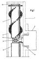
- the carpet care device shown has a dash-dotted housing 1. This is approximately T-shaped. In the T-bar 2 there is a gear motor, not shown, while the T-bar 3 receives brush rollers 4, 5.
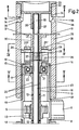
- a gear bridge 6 is fastened in the T-web 2 of the housing 1. This sits on both sides of a middle drive point in two Half shells 7, 8 on.
- a drive gear 9 extends between the two half-shells 7, 8 and sits non-rotatably and immovably on a hub 10. The latter protrudes on both sides of the drive gear 9 forming the drive point and forms counter-claws 11 at the end.
- clutch claws 12 which are arranged coaxially to the hub 10 and have clutch bushings 13 which pass through the inner rings 14 of ball bearings 15.
- the ball bearings 15 are embedded in the half-shells 7, 8 of the gear bridge and secured there by shoulders 16, 17.
- a cup-shaped sleeve 18 is pushed over each half-shell 7, 8, the cup edge 18 'of which is supported on a step 19' of the gear bridge 6.
- Each coupling sleeve 13 is provided with resilient fingers 20 which extend in the axial direction and which form bevels 21 at their ends facing away from the drive point.
- the finger ends 22 extend in front of the inner rings 14 of the ball bearings 15.
- the coupling bushes 13 are axially immovable by a support shoulder 23 opposite the finger ends 22.
- each coupling sleeve 13 continues into a head piece 24.
- four bayonet slots 25 are worked in from the front side of the head piece 24 in such a way that the insertion ends 25 'are widened in a funnel shape.
- the head piece contains a central bore 26 for receiving a compression spring 27.
- the bayonet slots 25 crosswise arranged webs 28 engage, which connect the brush roller casing 29 to the hub 30 of the brush roller.
- the webs 28 extend in the sections 25 "of the bayonet slots 25.
- the brush rollers 4, 5 are equipped with spoke walls 31 which connect the hub 30 to the casing 29.
- each lid 32 has a pot shape.
- the outwardly directed pot edge 33 is supported on the front end of the brush roller 4 or 5. From the bottom of the pot, there are webs 34 directed inward of the brush rollers, the outward-facing latching lugs 35 of which engage with clips in the shape-matched openings 36 of the brush roller 4 and 5, respectively.
- Each pot bottom of the cover 32 forms brush-oriented bushes 37.
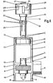
- the free ends 39 of a support mandrel 40 which supports the hub 10 of the drive gear 9, the coupling bushes 13, the head pieces 24 and the hubs 30 of the brush rollers 4, protrude into the inlet bores 38 of the bushes 37 of the cover , 5 interspersed. All of the above-mentioned components are rotatably seated on the mandrel 40, so that the drive gear 9, which is rotated by a worm (not shown), drives the coupling sleeves 13 with the head pieces 24 attached to them via the claw coupling connections 11, 12, which in turn, according to the bayonet slots 25, the Take brush rollers 4, 5 with you.
- the last assembly step is to bring the brush rollers 4, 5 into a snap-in connection with the head pieces 24.
- the webs 28 are inserted into the bayonet slots 25, the compression spring 27 serving as an ejector spring being charged. After the brush roller has been rotated, the webs 28 reach the internally assigned sections 25 ′′ of the bayonet slots 25.
- covers 32 are not yet assigned to the brush rollers 4, 5, this can then be done by clipping them on, so that the ends of the support mandrel 40 lie in the inlet bores 38 of the covers 32, thereby achieving an axial securing of the position.
- the brush rollers 4, 5 are replaced by pressure on them in the direction of the drive position and subsequent rotation, the webs 28 of the brush rollers 4 being able to leave the bayonet slots 25.
- the removal of the brush rollers from the support mandrel is supported by the ejector springs 27.
Landscapes
- Engineering & Computer Science (AREA)
- Mechanical Engineering (AREA)
- Treatment Of Fiber Materials (AREA)
- Brushes (AREA)
- Carpets (AREA)
- Saccharide Compounds (AREA)
- Cleaning In General (AREA)
- Catalysts (AREA)
- Pharmaceuticals Containing Other Organic And Inorganic Compounds (AREA)
- Nitrogen Condensed Heterocyclic Rings (AREA)
- Socks And Pantyhose (AREA)
- Spinning Methods And Devices For Manufacturing Artificial Fibers (AREA)
- Nozzles For Electric Vacuum Cleaners (AREA)
- Massaging Devices (AREA)
- Mechanical Operated Clutches (AREA)
Claims (4)
Priority Applications (1)
| Application Number | Priority Date | Filing Date | Title |
|---|---|---|---|
| AT82101090T ATE32301T1 (de) | 1981-04-11 | 1982-02-15 | Teppich-pflegegeraet. |
Applications Claiming Priority (2)
| Application Number | Priority Date | Filing Date | Title |
|---|---|---|---|
| DE3114753 | 1981-04-11 | ||
| DE19813114753 DE3114753A1 (de) | 1981-04-11 | 1981-04-11 | Teppich-pflegegeraet |
Publications (3)
| Publication Number | Publication Date |
|---|---|
| EP0062743A2 EP0062743A2 (fr) | 1982-10-20 |
| EP0062743A3 EP0062743A3 (en) | 1986-01-15 |
| EP0062743B1 true EP0062743B1 (fr) | 1988-02-03 |
Family
ID=6129972
Family Applications (1)
| Application Number | Title | Priority Date | Filing Date |
|---|---|---|---|
| EP82101090A Expired EP0062743B1 (fr) | 1981-04-11 | 1982-02-15 | Dispositif de soins pour tapis |
Country Status (8)
| Country | Link |
|---|---|
| US (1) | US4437199A (fr) |
| EP (1) | EP0062743B1 (fr) |
| AT (1) | ATE32301T1 (fr) |
| DE (2) | DE3114753A1 (fr) |
| DK (1) | DK151928C (fr) |
| ES (1) | ES509740A0 (fr) |
| FI (1) | FI74203C (fr) |
| NO (1) | NO154983C (fr) |
Families Citing this family (4)
| Publication number | Priority date | Publication date | Assignee | Title |
|---|---|---|---|---|
| DE19621301A1 (de) * | 1996-05-28 | 1997-12-04 | Vorwerk Co Interholding | Motorangetriebenes Bürstengerät |
| DE102004046383B4 (de) | 2004-09-24 | 2009-06-18 | Stein & Co Gmbh | Vorrichtung für Bürstwalze von Bodenpflegegeräten |
| DE102011116419B4 (de) | 2011-10-18 | 2013-07-25 | Stein & Co. Gmbh | Bürstenwalze eines Bodenpflegegerätes |
| EP2768371B1 (fr) | 2011-10-18 | 2016-03-02 | Stein & Co. GmbH | Ensemble palier de brosse rotative |
Citations (1)
| Publication number | Priority date | Publication date | Assignee | Title |
|---|---|---|---|---|
| US2969556A (en) * | 1957-11-23 | 1961-01-31 | Grasmann Josef | Floor cleaning machine |
Family Cites Families (5)
| Publication number | Priority date | Publication date | Assignee | Title |
|---|---|---|---|---|
| CH262056A (de) * | 1945-05-19 | 1949-06-15 | Sulzer Ag | Anlage mit Klauenkupplung. |
| GB842668A (en) * | 1958-01-01 | 1960-07-27 | Glenhose Ltd | Fitment for vacuum cleaners for applying the same to use for different purposes |
| US4026397A (en) * | 1975-10-06 | 1977-05-31 | Xerox Corporation | Control knob clutches with lock |
| DE2615511A1 (de) * | 1976-04-09 | 1977-10-20 | Fhn Verbindungstechnik Gmbh | Getriebe, insbesondere fuer elektrische fensterheber in kraftfahrzeugen |
| DE2741912C3 (de) * | 1977-09-17 | 1981-10-15 | Klaus 5620 Velbert Stein | Sicherheits-Ausrückkupplung für den Antrieb der rotierenden Bürsten von Bodenpflegemaschinen |
-
1981
- 1981-04-11 DE DE19813114753 patent/DE3114753A1/de not_active Withdrawn
-
1982
- 1982-01-27 FI FI820263A patent/FI74203C/fi not_active IP Right Cessation
- 1982-02-15 EP EP82101090A patent/EP0062743B1/fr not_active Expired
- 1982-02-15 AT AT82101090T patent/ATE32301T1/de not_active IP Right Cessation
- 1982-02-15 DE DE8282101090T patent/DE3278071D1/de not_active Expired
- 1982-02-19 ES ES509740A patent/ES509740A0/es active Granted
- 1982-03-12 DK DK108482A patent/DK151928C/da not_active IP Right Cessation
- 1982-03-22 US US06/360,498 patent/US4437199A/en not_active Expired - Fee Related
- 1982-04-06 NO NO821172A patent/NO154983C/no unknown
Patent Citations (1)
| Publication number | Priority date | Publication date | Assignee | Title |
|---|---|---|---|---|
| US2969556A (en) * | 1957-11-23 | 1961-01-31 | Grasmann Josef | Floor cleaning machine |
Also Published As
| Publication number | Publication date |
|---|---|
| NO154983C (no) | 1987-01-28 |
| NO154983B (no) | 1986-10-20 |
| ES8301613A1 (es) | 1983-01-16 |
| DK108482A (da) | 1982-10-12 |
| ES509740A0 (es) | 1983-01-16 |
| DK151928C (da) | 1988-08-01 |
| US4437199A (en) | 1984-03-20 |
| DE3278071D1 (en) | 1988-03-10 |
| EP0062743A3 (en) | 1986-01-15 |
| FI74203C (fi) | 1988-01-11 |
| EP0062743A2 (fr) | 1982-10-20 |
| FI74203B (fi) | 1987-09-30 |
| DK151928B (da) | 1988-01-18 |
| ATE32301T1 (de) | 1988-02-15 |
| NO821172L (no) | 1982-10-12 |
| DE3114753A1 (de) | 1982-10-28 |
| FI820263L (fi) | 1982-10-12 |
Similar Documents
| Publication | Publication Date | Title |
|---|---|---|
| DE60005285T2 (de) | Befestigungsanordnung für ein elektrisches Gerät, wie ein Starter-Generator, in einem Kupplungsgehäuse eines Kraftfahrzeugs | |
| DE1813638A1 (de) | Elektrischer Antriebsmotor fuer Scheibenwischer,insbesondere von Kraftfahrzeugen | |
| DE2805045C2 (de) | Wälzlager-Ausrücker | |
| EP0062743B1 (fr) | Dispositif de soins pour tapis | |
| DE19830890B4 (de) | Dreiringnadellagerung für einen Pumpenteil | |
| DE19843226B4 (de) | Lageranordnung für einen Elektrokleinstmotor | |
| DE3003698C2 (de) | Rad für Spiel- und Demonstrationszwecke | |
| DE2818847A1 (de) | Buerst- und/oder klopfwalze fuer staubsauger o.dgl. | |
| DE1923753A1 (de) | Elektromotor mit Feldmagnet aus Ferrit und Verfahren zu seiner Herstellung | |
| DE2021409A1 (de) | Elektrostatisches Kopiergeraet | |
| EP0482235A1 (fr) | Moteur à bagues ou moteur commutateur | |
| EP0325943B1 (fr) | Accouplement rapide entre un arbre et un moyeu | |
| DE3220388C2 (de) | Lenkrolle für Möbel, Apparate u. dgl. Objekte | |
| DE3925021A1 (de) | Befestigung eines rades auf einer welle | |
| DE719879C (de) | Dichtungseinrichtung, insbesondere fuer die Wellen der Kuehlwasserpumpen von Kraftfahrzeugen | |
| DE2856310B2 (de) | Lageranordnung für den eine Wicklung und einen Kommutator aufweisenden Läufer einer elektrischen Maschine | |
| DE1939505A1 (de) | Elektrisch betriebenes Handwerkzeug | |
| DE2228724C3 (de) | Gelenkige Kupplung zum Antrieb der Bürsten in einer Schuhputzmaschine | |
| DE1138457B (de) | Staenderanordnung fuer elektrische Gleichstromkleinstmotoren | |
| DE454728C (de) | Kegelraedergetriebe | |
| DE10056986A1 (de) | Verfahren und Vorrichtung zur Montage oder Demontage von Antriebselementen eines Haushaltgeräts | |
| DE2333552C3 (de) | Schreibwalze für Schreibmaschinen und dergleichen | |
| DE2043276A1 (de) | Reibkorperumlaufgetnebe | |
| CH659431A5 (de) | Typenrad. | |
| DE7827935U1 (de) | Elektromotorisch verstellbarer spiegel |
Legal Events
| Date | Code | Title | Description |
|---|---|---|---|
| PUAI | Public reference made under article 153(3) epc to a published international application that has entered the european phase |
Free format text: ORIGINAL CODE: 0009012 |
|
| AK | Designated contracting states |
Designated state(s): AT CH DE FR GB IT SE |
|
| 17P | Request for examination filed |
Effective date: 19830114 |
|
| PUAL | Search report despatched |
Free format text: ORIGINAL CODE: 0009013 |
|
| AK | Designated contracting states |
Designated state(s): AT CH DE FR GB IT LI SE |
|
| 17Q | First examination report despatched |
Effective date: 19861124 |
|
| R17C | First examination report despatched (corrected) |
Effective date: 19870130 |
|
| GRAA | (expected) grant |
Free format text: ORIGINAL CODE: 0009210 |
|
| AK | Designated contracting states |
Kind code of ref document: B1 Designated state(s): AT CH DE FR GB IT LI SE |
|
| REF | Corresponds to: |
Ref document number: 32301 Country of ref document: AT Date of ref document: 19880215 Kind code of ref document: T |
|
| GBT | Gb: translation of ep patent filed (gb section 77(6)(a)/1977) | ||
| REF | Corresponds to: |
Ref document number: 3278071 Country of ref document: DE Date of ref document: 19880310 |
|
| ET | Fr: translation filed | ||
| ITF | It: translation for a ep patent filed |
Owner name: STUDIO JAUMANN |
|
| PLBE | No opposition filed within time limit |
Free format text: ORIGINAL CODE: 0009261 |
|
| STAA | Information on the status of an ep patent application or granted ep patent |
Free format text: STATUS: NO OPPOSITION FILED WITHIN TIME LIMIT |
|
| 26N | No opposition filed | ||
| PGFP | Annual fee paid to national office [announced via postgrant information from national office to epo] |
Ref country code: SE Payment date: 19900112 Year of fee payment: 9 |
|
| PGFP | Annual fee paid to national office [announced via postgrant information from national office to epo] |
Ref country code: FR Payment date: 19900118 Year of fee payment: 9 |
|
| PGFP | Annual fee paid to national office [announced via postgrant information from national office to epo] |
Ref country code: AT Payment date: 19900206 Year of fee payment: 9 |
|
| PGFP | Annual fee paid to national office [announced via postgrant information from national office to epo] |
Ref country code: DE Payment date: 19900208 Year of fee payment: 9 |
|
| ITTA | It: last paid annual fee | ||
| PGFP | Annual fee paid to national office [announced via postgrant information from national office to epo] |
Ref country code: GB Payment date: 19900228 Year of fee payment: 9 |
|
| PGFP | Annual fee paid to national office [announced via postgrant information from national office to epo] |
Ref country code: CH Payment date: 19900504 Year of fee payment: 9 |
|
| PG25 | Lapsed in a contracting state [announced via postgrant information from national office to epo] |
Ref country code: GB Effective date: 19910215 Ref country code: AT Effective date: 19910215 |
|
| PG25 | Lapsed in a contracting state [announced via postgrant information from national office to epo] |
Ref country code: SE Effective date: 19910216 |
|
| PG25 | Lapsed in a contracting state [announced via postgrant information from national office to epo] |
Ref country code: LI Effective date: 19910228 Ref country code: CH Effective date: 19910228 |
|
| GBPC | Gb: european patent ceased through non-payment of renewal fee | ||
| PG25 | Lapsed in a contracting state [announced via postgrant information from national office to epo] |
Ref country code: FR Effective date: 19911031 |
|
| REG | Reference to a national code |
Ref country code: CH Ref legal event code: PL |
|
| PG25 | Lapsed in a contracting state [announced via postgrant information from national office to epo] |
Ref country code: DE Effective date: 19911101 |
|
| REG | Reference to a national code |
Ref country code: FR Ref legal event code: ST |
|
| EUG | Se: european patent has lapsed |
Ref document number: 82101090.7 Effective date: 19911008 |