EP0062743B1 - Carpet care apparatus - Google Patents
Carpet care apparatus Download PDFInfo
- Publication number
- EP0062743B1 EP0062743B1 EP82101090A EP82101090A EP0062743B1 EP 0062743 B1 EP0062743 B1 EP 0062743B1 EP 82101090 A EP82101090 A EP 82101090A EP 82101090 A EP82101090 A EP 82101090A EP 0062743 B1 EP0062743 B1 EP 0062743B1
- Authority
- EP
- European Patent Office
- Prior art keywords
- brush rollers
- shaft
- carrier pin
- coupling
- head pieces
- Prior art date
- Legal status (The legal status is an assumption and is not a legal conclusion. Google has not performed a legal analysis and makes no representation as to the accuracy of the status listed.)
- Expired
Links
Images

Classifications
-
- A—HUMAN NECESSITIES
- A47—FURNITURE; DOMESTIC ARTICLES OR APPLIANCES; COFFEE MILLS; SPICE MILLS; SUCTION CLEANERS IN GENERAL
- A47L—DOMESTIC WASHING OR CLEANING; SUCTION CLEANERS IN GENERAL
- A47L9/00—Details or accessories of suction cleaners, e.g. mechanical means for controlling the suction or for effecting pulsating action; Storing devices specially adapted to suction cleaners or parts thereof; Carrying-vehicles specially adapted for suction cleaners
- A47L9/02—Nozzles
- A47L9/04—Nozzles with driven brushes or agitators
-
- A—HUMAN NECESSITIES
- A47—FURNITURE; DOMESTIC ARTICLES OR APPLIANCES; COFFEE MILLS; SPICE MILLS; SUCTION CLEANERS IN GENERAL
- A47L—DOMESTIC WASHING OR CLEANING; SUCTION CLEANERS IN GENERAL
- A47L5/00—Structural features of suction cleaners
- A47L5/12—Structural features of suction cleaners with power-driven air-pumps or air-compressors, e.g. driven by motor vehicle engine vacuum
- A47L5/22—Structural features of suction cleaners with power-driven air-pumps or air-compressors, e.g. driven by motor vehicle engine vacuum with rotary fans
- A47L5/28—Suction cleaners with handles and nozzles fixed on the casings, e.g. wheeled suction cleaners with steering handle
- A47L5/30—Suction cleaners with handles and nozzles fixed on the casings, e.g. wheeled suction cleaners with steering handle with driven dust-loosening tools, e.g. rotating brushes
Definitions
- the invention relates to a carpet care device according to the preamble of claim 1.
- the object of the invention is to design and develop the known maintenance device in such a way that torque transmission is as favorable as possible and manufacture is as inexpensive as possible.
- a generic carpet care device which is characterized on the one hand by favorable torque transmission due to lower forces and on the other hand has the advantage of lower production costs.
- the torque transfer of the brush rollers now takes place via the hollow shaft, while the support is carried out via the support mandrel.
- the mandrel has only the function of a support function. It can be smooth throughout and thus represents a very simple, inexpensive to manufacture automatic part.
- the torque transmission to the brush rollers takes place via the counterclaws of the hub of the drive gear, which counterclaws engage positively in the clutch claws of the clutch bushings, which carry end pieces at the end. These are in turn plug-in with the brush rollers.
- the shaft receives a bridge-like support on both sides of the drive system through the ball bearings on the housing side, which are penetrated by the coupling sleeves of the head pieces.
- the brush rollers and the components interacting with them can be assembled by means of plug-in assembly.
- the drive wheel and the ball bearings on both sides of it are to be positioned.
- the coupling sleeves are then to be inserted through the ball bearings, the coupling claws of which engage in the counterclaws of the hub of the drive gear.
- the next step is to push the brush rollers onto the shaft ends, making the push-fit with the head pieces. Replacing the brush rollers after any wear is therefore also very simplified.
- the coupling sleeves have resilient fingers with bevels that snap in front of the inner ring of the ball bearing. This means that after the coupling bushes have been pushed through the ball bearings, the coupling bushes are fixed in the axial direction. If the shaft is then inserted, the resilient fingers cannot come out of their locked position.
- the ball bearings are surrounded by cup-shaped sleeves of the housing and the shaft extends beyond the sleeves into the hubs of the brush rollers, the end openings of which are closed by clipped-on covers which have a cup-shaped entry bore for the end of the shaft .
- the housing sections accommodating the ball bearings can accordingly be of shell-like design. The insertion of the ball bearings is simplified.
- the cup-shaped sleeves placed on the housing sections secure the position of the ball bearings, which also support the shaft. The ends of these engage in the hubs of the brush rollers and in the cup-shaped entry bores of the covers clipped into the front end openings.
- the two covers are used to axially secure the shaft. After removing a cover, it is possible to pull out the shaft.
- ejector springs for the brush rollers can be assigned to the head pieces.
- the carpet care device shown has a dash-dotted housing 1. This is approximately T-shaped. In the T-bar 2 there is a gear motor, not shown, while the T-bar 3 receives brush rollers 4, 5.
- a gear bridge 6 is fastened in the T-web 2 of the housing 1. This sits on both sides of a middle drive point in two Half shells 7, 8 on.
- a drive gear 9 extends between the two half-shells 7, 8 and sits non-rotatably and immovably on a hub 10. The latter protrudes on both sides of the drive gear 9 forming the drive point and forms counter-claws 11 at the end.
- clutch claws 12 which are arranged coaxially to the hub 10 and have clutch bushings 13 which pass through the inner rings 14 of ball bearings 15.
- the ball bearings 15 are embedded in the half-shells 7, 8 of the gear bridge and secured there by shoulders 16, 17.
- a cup-shaped sleeve 18 is pushed over each half-shell 7, 8, the cup edge 18 'of which is supported on a step 19' of the gear bridge 6.
- Each coupling sleeve 13 is provided with resilient fingers 20 which extend in the axial direction and which form bevels 21 at their ends facing away from the drive point.
- the finger ends 22 extend in front of the inner rings 14 of the ball bearings 15.
- the coupling bushes 13 are axially immovable by a support shoulder 23 opposite the finger ends 22.
- each coupling sleeve 13 continues into a head piece 24.
- four bayonet slots 25 are worked in from the front side of the head piece 24 in such a way that the insertion ends 25 'are widened in a funnel shape.
- the head piece contains a central bore 26 for receiving a compression spring 27.
- the bayonet slots 25 crosswise arranged webs 28 engage, which connect the brush roller casing 29 to the hub 30 of the brush roller.
- the webs 28 extend in the sections 25 "of the bayonet slots 25.
- the brush rollers 4, 5 are equipped with spoke walls 31 which connect the hub 30 to the casing 29.
- each lid 32 has a pot shape.
- the outwardly directed pot edge 33 is supported on the front end of the brush roller 4 or 5. From the bottom of the pot, there are webs 34 directed inward of the brush rollers, the outward-facing latching lugs 35 of which engage with clips in the shape-matched openings 36 of the brush roller 4 and 5, respectively.
- Each pot bottom of the cover 32 forms brush-oriented bushes 37.
- the free ends 39 of a support mandrel 40 which supports the hub 10 of the drive gear 9, the coupling bushes 13, the head pieces 24 and the hubs 30 of the brush rollers 4, protrude into the inlet bores 38 of the bushes 37 of the cover , 5 interspersed. All of the above-mentioned components are rotatably seated on the mandrel 40, so that the drive gear 9, which is rotated by a worm (not shown), drives the coupling sleeves 13 with the head pieces 24 attached to them via the claw coupling connections 11, 12, which in turn, according to the bayonet slots 25, the Take brush rollers 4, 5 with you.
- the last assembly step is to bring the brush rollers 4, 5 into a snap-in connection with the head pieces 24.
- the webs 28 are inserted into the bayonet slots 25, the compression spring 27 serving as an ejector spring being charged. After the brush roller has been rotated, the webs 28 reach the internally assigned sections 25 ′′ of the bayonet slots 25.
- covers 32 are not yet assigned to the brush rollers 4, 5, this can then be done by clipping them on, so that the ends of the support mandrel 40 lie in the inlet bores 38 of the covers 32, thereby achieving an axial securing of the position.
- the brush rollers 4, 5 are replaced by pressure on them in the direction of the drive position and subsequent rotation, the webs 28 of the brush rollers 4 being able to leave the bayonet slots 25.
- the removal of the brush rollers from the support mandrel is supported by the ejector springs 27.
Abstract
Description
Die Erfindung betrifft ein Teppich-Pflegegerät gemäß Oberbegriff des Anspruchs 1.The invention relates to a carpet care device according to the preamble of
Bei einem bekannten Pflegegerät, dort allerdings einem reinen Boden-Pflegegerät (vergl. US-A-2 969 556) werden die Bürstenwalzen über miteinander im Eingriff stehende Zahnräder angetrieben, wobei eines der Zahnräder auf einer zentralen, die Bürstenwalzen durchsetzenden und diese antreibenden Welle angebracht ist. Hiermit ist bei dem bekannten Pflegegerät eine ungünstige Drehmomentübertragung verbunden, da aufgrund der mittigen Anordnung der Antriebswelle relativ hohe Kräfte notwendig sind. Die Zahnräder müssen beispielsweise hinsichtlich dieser Kräfte ausgelegt sein.In a known maintenance device, however, a pure floor maintenance device (see US Pat. No. 2,969,556), the brush rollers are driven via gearwheels which are in engagement with one another, one of the gearwheels being mounted on a central shaft which passes through and drives the brush rollers is. This is associated with an unfavorable torque transmission in the known maintenance device, since relatively high forces are necessary due to the central arrangement of the drive shaft. The gears must be designed for these forces, for example.
Im Hinblick auf den bekannten Stand der Technik stellt sich der Erfindung die Aufgabe, das bekannte Pflegegerät so auszugestalten und weiterzubilden, daß eine möglichst günstige Drehmomentübertragung und eine möglichst kostengünstige Herstelibarkeit gegeben ist.In view of the known state of the art, the object of the invention is to design and develop the known maintenance device in such a way that torque transmission is as favorable as possible and manufacture is as inexpensive as possible.
Diese Aufgabe ist durch die im Kennzeichnungsteil des Anspruchs 1 aufgeführten Merkmale gelöst.This object is achieved by the features listed in the characterizing part of
Zufolge derartiger Ausgestaltung ist ein gattungsgemäßes Teppich-Pflegegerät angegeben, welches sich einerseits durch eine günstige Drehmomentübertragung, aufgrund geringerer Kräfte, auszeichnet und andererseits den Vorteil geringerer Herstellungskosten besitzt. Die Drehmomentübertragung der Bürstenwalzen erfolgt nun über die Hohlwelle, die Abstützung dagegen über den Tragdorn. Der Tragdorn hat nur die Aufgabe einer Stützfunktion. Er kann durchgehend glatt ausgebildet sein und stellt dadurch ein sehr einfaches, kostengünstig zu fertigendes Automatenteil dar. Die Drehmomentübertragung auf die Bürstenwalzen geschieht über die Gegenklauen der Nabe des Antriebszahnrades, welche Gegenklauen formschlüssig in die Kupplungsklauen der Kupplungsbüchsen eingreifen, die endseitig Kopfstücke tragen. Die stehen wiederum in Steck-Rastverbindung mit den Bürstenwalzen. Eine beiderseits der Antriebsstelie brückenartige Abstützung erhält die Welle durch die von den Kupplungsbüchsen der Kopfstücke durchsetzten gehäuseseitigen Kugellagern. Das Montieren der Bürstenwalzen und der mit diesen zusammenwirkenden Bauteile kann im Wege der Steckmontage ausgeführt werden. Vorerst sind das Antriebsrad sowie die beiderseits davon befindlichen Kugellager zu positionieren. Anschließend sind die Kupplungsbüchsen durch die Kugellager zu stecken, deren Kupplungsklauen in die Gegenklauen der Nabe des Antriebszahnrades eingreifen. Der nächste Arbeitsschritt besteht darin, die Bürstenwalzen auf die Wellenenden aufzuschieben unter Herstellung der Steck-Verrastung mit den Kopfstücken. Ein Auswechseln der Bürstenwalzen nach einem etwaigen Verschleiß ist daher auch sehr vereinfacht.As a result of such a design, a generic carpet care device is specified which is characterized on the one hand by favorable torque transmission due to lower forces and on the other hand has the advantage of lower production costs. The torque transfer of the brush rollers now takes place via the hollow shaft, while the support is carried out via the support mandrel. The mandrel has only the function of a support function. It can be smooth throughout and thus represents a very simple, inexpensive to manufacture automatic part. The torque transmission to the brush rollers takes place via the counterclaws of the hub of the drive gear, which counterclaws engage positively in the clutch claws of the clutch bushings, which carry end pieces at the end. These are in turn plug-in with the brush rollers. The shaft receives a bridge-like support on both sides of the drive system through the ball bearings on the housing side, which are penetrated by the coupling sleeves of the head pieces. The brush rollers and the components interacting with them can be assembled by means of plug-in assembly. For the time being, the drive wheel and the ball bearings on both sides of it are to be positioned. The coupling sleeves are then to be inserted through the ball bearings, the coupling claws of which engage in the counterclaws of the hub of the drive gear. The next step is to push the brush rollers onto the shaft ends, making the push-fit with the head pieces. Replacing the brush rollers after any wear is therefore also very simplified.
Eine vorteilhafte Weiterbildung besteht darin, daß die Kupplungsbüchsen federnde Finger mit Auflaufschrägen besitzen, welche vor den Kugellager-Innenring schnappen. Das bedeutet, daß nach Durchstecken der Kupplungsbüchsen durch die Kugellager die Kupplungsbüchsen in Achsrichtung fixiert sind. Wird dann die Welle eingebracht, können die federnden Finger nicht aus inrer Sicherungsstellung treten.An advantageous development is that the coupling sleeves have resilient fingers with bevels that snap in front of the inner ring of the ball bearing. This means that after the coupling bushes have been pushed through the ball bearings, the coupling bushes are fixed in the axial direction. If the shaft is then inserted, the resilient fingers cannot come out of their locked position.
Ein weiteres vorteilhaftes Merkmal besteht darin, daß die Kugellager von topfförmigen Hülsen des Gehäuses umfaßt sind und die Welle sich über die Hülsen hinaus bis in Naben der Bürstenwalzen erstreckt, deren Stirnendöffnungen von eingeklipsten Deckeln verschlossen sind, die eine topfförmige Eintrittsbohrung für das Ende der Welle besitzen. Die die Kugellager aufnehmenden Gehäuseabschnitte können demgemäß schalenartig ausgebildet sein. Das Einsetzen der Kugellager ist dadurch vereinfacht. Die auf die Gehäuseabschnitte gesteckten topfförmigen Hülsen sichern die Lage der Kugeliager, welche gleichzeitig die Welle abstützen. Die Enden derselben greifen in die Naben der Bürstenwalzen ein sowie in die topfförmigen Eintrittsbohrungen der in den Stirnendöffnungen eingeklipsten Deckel. Die beiden Deckel dienen zur axialen Lagesicherung der Welle. Nach Entfernen eines Deckels ist es möglich, die Welle herauszuziehen.Another advantageous feature is that the ball bearings are surrounded by cup-shaped sleeves of the housing and the shaft extends beyond the sleeves into the hubs of the brush rollers, the end openings of which are closed by clipped-on covers which have a cup-shaped entry bore for the end of the shaft . The housing sections accommodating the ball bearings can accordingly be of shell-like design. The insertion of the ball bearings is simplified. The cup-shaped sleeves placed on the housing sections secure the position of the ball bearings, which also support the shaft. The ends of these engage in the hubs of the brush rollers and in the cup-shaped entry bores of the covers clipped into the front end openings. The two covers are used to axially secure the shaft. After removing a cover, it is possible to pull out the shaft.
Damit die Bürstenwalzen nicht ungewollt aus ihrer vorschriftsmäßigen Steck-Rastverbindung treten, können den Kopfstücken Auswerferfedern für die Bürstenwalzen zugeordnet sein.So that the brush rollers do not inadvertently come out of their proper plug-snap connection, ejector springs for the brush rollers can be assigned to the head pieces.
Nachstehend wird ein Ausführungsbeispiel der Erfindung anhand der Fig. 1 bis 6 erläutert. Es zeigt:
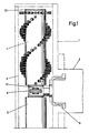
- Fig. 1 in etwa natürlichem Maßstab strichpunktiert ein Gehäuse eines Teppich-Pflegegeräts, welches beiderseits der Antriebsstelle fliegend ausladende, auf einer Welle angeordnete Bürstenwalzen aufweist, wobei bei einer Bürstenwalze zwecks vereinfachter Darstellung die Bürsten nicht veranschaulicht sind,
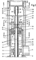
- Fig. 2 einen Längsmittelschnitt durch eine auf der Welle angeordnete Bürstenwalze,
- Fig. 3 den Schnitt nach der Linie 111-111 in Fig. 2,
- Fig. 4 den Schnitt nach der Linie IV-IV in Fig. 2,
- Fig. 5 den Schnitt nach der Linie V-V in Fig. 2 und
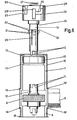
- Fig. 6 teils in Ansicht, teils im Schnitt eine Vormontagestellung, und zwar vor dem Einsetzen eines mit einer Kupplungsbüchse versehenen Kopfstückes.
- 1 on a natural scale, dash-dotted lines, a housing of a carpet care device, which has on both sides of the drive point overhanging brush rollers arranged on a shaft, the brushes not being illustrated in the case of a brush roller for the purpose of simplified illustration,
- 2 shows a longitudinal central section through a brush roller arranged on the shaft,
- 3 shows the section along the line 111-111 in Fig. 2,
- 4 shows the section along the line IV-IV in FIG. 2,
- Fig. 5 shows the section along the line VV in Fig. 2 and
- Fig. 6, partly in view, partly in section, a pre-assembly position, before inserting a head piece provided with a coupling sleeve.
Das dargestellte Teppich-Pflegegerät besitzt ein strichpunktiert dargestelltes Gehäuse 1. Dieses ist etwa T-förmig gestaltet. In dem T-Steg 2 befindet sich ein nicht veranschaulichter Getriebemotor, während der T-Balken 3 Bürstenwalzen 4, 5 aufnimmt.The carpet care device shown has a dash-dotted
In dem T-Steg 2 des Gehäuses 1 ist eine Getriebebrücke 6 befestigt. Diese setzt sich beiderseits einer mittleren Antriebsstelle in zwei Halbschalen 7, 8 fort. Zwischen beiden Halbschalen 7, 8 erstreckt sich ein Antriebszahnrad 9, welches undrehbar und unverschieblich auf einer Nabe 10 sitzt. Letztere überragt beidseitig das die Antriebsstelle bildende Antriebszahnrad 9 und formt endseitig Gegenklauen 11. Diese stehen in formschlüssigem Eingriff mit Kupplungsklauen 12 koaxial zur Nabe 10 angeordneter Kupplungsbüchsen 13, die Innenringe 14 von Kugellagern 15 durchsetzen. Die Kugellager 15 sind eingelassen in die Halbschalen 7, 8 der Getriebebrücke und dort von Schultern 16, 17 gesichert. Über jede Halbschale 7, 8 ist eine topfförmige Hülse 18 geschoben, deren Topfrand 18' sich an einer Stufe 19' der Getriebebrücke 6 abstützt.A
Jede Kupplungsbüchse 13 ist mit sich in Achsrichtung erstreckenden federnden Fingern 20 versehen, welche an ihrem der Antriebsstelle abgewendeten Enden Auflaufschrägen 21 ausbilden. Die Fingerenden 22 erstrecken sich vor den Innenringen 14 der Kugellager 15. Eine axiale Unverschieblichkeit erhalten die Kupplungsbüchsen 13 durch eine den Fingerenden 22 gegenüberliegende Stützschulter 23.Each
Jenseits der Stützschulter 23 setzt sich jede Kupplungsbüchse 13 in ein Kopfstück 24 fort. Von der Stirnseite des Kopfstückes 24 sind beim Ausführungsbeispiel vier Bajonettschlitze 25 eingearbeitet derart, daß die Einführenden 25' trichterförmig erbreitert sind. Sodann enthält das Kopfstück eine mittlere Bohrung 26 zur Aufnahme einer Druckfeder 27. In die Bajonettschlitze 25 greifen kreuzend zueinander angeordnete Stege 28 ein, die den Bürstenwalzen-Mantel 29 mit der Nabe 30 der Bürstenwalze verbinden. Die Stege 28 erstrecken sich in den Abschnitten 25" der Bajonettschlitze 25. Zufolge der Druckfeder 27, die sich einerseits am Kopfstück 24 und andererseits an der Nabe 30 der Bürstenwalze abstützt, verbleiben die Stege in den Abschnitten 25".Beyond the
Ferner sind die Bürstenwalzen 4, 5 mit Speichenwänden 31 ausgestattet, die die Nabe 30 mit dem Mantel 29 verbinden.Furthermore, the
Die Stirnendöffnungen der Bürstenwalzen 4, 5 sind von eingeklipsten Deckeln 32 verschlossen. Im einzelnen besitzt jeder Deckel 32 eine Topfform. Der auswärtsgerichtete Topfrand 33 stützt sich an dem Stirnende der Bürstenwalze 4 bzw. 5 ab. Vom Topfboden gehen bürstenwalzeneinwärts gerichtete Stege 34 aus, deren auswärts weisende Rastnasen 35 klipsend in formangepaßte Öffnungen 36 der Bürstenwalze 4 bzw. 5 eingreifen.The end openings of the
Jeder Topfboden der Deckel 32 formt bürsteneinwärtsgerichtete Büchsen 37. In die Eintrittsbohrungen 38 der Büchsen 37 der Deckel ragen die freien Enden 39 eines Tragdorns 40, welcher die Nabe 10 des Antriebszahnrades 9, die Kupplungsbüchsen 13, die Kopfstücke 24 sowie die Naben 30 der Bürstenwalzen 4, 5 durchsetzt. Sämtliche vorstehend genannten Bauteile sitzen drehbar auf dem Tragdorn 40, so daß das von einer nicht dargestellten Schnecke in Umdrehung versetzte Antriebszahnrad 9 über die Klauenkupplungs-Verbindungen 11, 12 die Kupplungsbüchsen 13 mit den daran befestigten Kopfstücken 24 antreibt, welche ihrerseits zufolge der Bajonettschlitze 25 die Bürstenwalzen 4, 5 mitnehmen.Each pot bottom of the
Die Montage der mit den Bürstenwalzen zusammenwirkenden Bauteile geschieht derart, daß vorerst in die Halbschalen 7, 8 der Getriebebrücke 6 die Kugellager 15 eingesetzt werden. Dann erfolgt das Aufschieben der Hülsen 18 auf die Halbschalen. Anschließend ist das Antriebszahnrad 9 in der Getriebebrücke 6 zu positionieren, woraufhin die Kupplungsbüchsen 13 unter Durchsetzen der Kugellager 15 angebracht werden. Deren Kupplungsklauen 12 treten dabei in Eingriff mit den Gegenklauen 11 der Nabe 10 des Antriebszahnrades 9. In der Endphase der Einsteckverlagerung der Kupplungsbüchsen 13 hintergreifen die zuvor federnd ausweichenden Finger 20 den Innenring 14 der Kugellager 15. Danach wird der Tragdorn 40 eingeschoben, der das Einwärtsfedern der Finger 20 ausschließt. Der letzte Montageschritt besteht darin, die Bürstenwalzen 4, 5 in Steck-Rastverbindung mit den Kopfstücken 24 zu bringen. Zu diesem Zweck werden die Stege 28 in die Bajonettschlitze 25 eingeführt, wobei die als Auswerferfeder dienende Druckfeder 27 aufgeladen wird. Nach einer Verdrehung der Bürstenwalze gelangen die Stege 28 in die innen zugeordneten Abschnitte 25" der Bajonettschlitze 25.The assembly of the components interacting with the brush rollers takes place in such a way that the
Sollten die Deckel 32 noch nicht den Bürstenwalzen 4, 5 zugeordnet sein, so kann dieses anschließend durch Aufklipsen geschehen, so daß der Tragdorn 40 mit seinen Enden 39 in den Eintrittsbohrungen 38 der Deckel 32 einliegt unter Erzielung einer axialen Lagesicherung.If the
Ein Auswechseln der Bürstenwalzen 4, 5 geschieht durch Druck auf diese in Richtung der Antriebsstelie und anschießender Drehung, wobei die Stege 28 der Bürstenwalzen 4, die Bajonettschlitze 25 verlassen können. Unterstützt wird das Abziehen der Bürstenwalzen von dem Tragdorn durch die Auswerferfedern 27.The
Claims (4)
characterized in that the coupling bushes (13) have resilient fingers (20) with run-on slopes (21) which snap in front of the ball-bearing inner ring (14).
characterized in that the ball bearings (15) are surrounded by pot-shaped sleeves (18) of the housing (1), and the shaft (40) extends beyond the sleeves (18) into the hubs (30) of the brush rollers (4, 5), the endface orifices of which are closed by means of snapped in covers (22) which have a pot-shaped entry bore (38) for the end (39) of the shaft (40).
characterized in that ejector springs (27) for the brush rollers (4, 5) are assigned to the head pieces (24).
Priority Applications (1)
| Application Number | Priority Date | Filing Date | Title |
|---|---|---|---|
| AT82101090T ATE32301T1 (en) | 1981-04-11 | 1982-02-15 | CARPET CARE DEVICE. |
Applications Claiming Priority (2)
| Application Number | Priority Date | Filing Date | Title |
|---|---|---|---|
| DE3114753 | 1981-04-11 | ||
| DE19813114753 DE3114753A1 (en) | 1981-04-11 | 1981-04-11 | CARPET CARE DEVICE |
Publications (3)
| Publication Number | Publication Date |
|---|---|
| EP0062743A2 EP0062743A2 (en) | 1982-10-20 |
| EP0062743A3 EP0062743A3 (en) | 1986-01-15 |
| EP0062743B1 true EP0062743B1 (en) | 1988-02-03 |
Family
ID=6129972
Family Applications (1)
| Application Number | Title | Priority Date | Filing Date |
|---|---|---|---|
| EP82101090A Expired EP0062743B1 (en) | 1981-04-11 | 1982-02-15 | Carpet care apparatus |
Country Status (8)
| Country | Link |
|---|---|
| US (1) | US4437199A (en) |
| EP (1) | EP0062743B1 (en) |
| AT (1) | ATE32301T1 (en) |
| DE (2) | DE3114753A1 (en) |
| DK (1) | DK151928C (en) |
| ES (1) | ES509740A0 (en) |
| FI (1) | FI74203C (en) |
| NO (1) | NO154983C (en) |
Families Citing this family (4)
| Publication number | Priority date | Publication date | Assignee | Title |
|---|---|---|---|---|
| DE19621301A1 (en) * | 1996-05-28 | 1997-12-04 | Vorwerk Co Interholding | Motorized brushing device |
| DE102004046383B4 (en) | 2004-09-24 | 2009-06-18 | Stein & Co Gmbh | Device for brushing roller of floor care appliances |
| DE102011116419B4 (en) | 2011-10-18 | 2013-07-25 | Stein & Co. Gmbh | Brush roller of a floor care device |
| WO2013056695A1 (en) | 2011-10-18 | 2013-04-25 | Stein & Co. Gmbh | Bearing arrangement of a rotating brush roller |
Citations (1)
| Publication number | Priority date | Publication date | Assignee | Title |
|---|---|---|---|---|
| US2969556A (en) * | 1957-11-23 | 1961-01-31 | Grasmann Josef | Floor cleaning machine |
Family Cites Families (5)
| Publication number | Priority date | Publication date | Assignee | Title |
|---|---|---|---|---|
| CH262056A (en) * | 1945-05-19 | 1949-06-15 | Sulzer Ag | System with claw coupling. |
| GB842668A (en) * | 1958-01-01 | 1960-07-27 | Glenhose Ltd | Fitment for vacuum cleaners for applying the same to use for different purposes |
| US4026397A (en) * | 1975-10-06 | 1977-05-31 | Xerox Corporation | Control knob clutches with lock |
| DE2615511A1 (en) * | 1976-04-09 | 1977-10-20 | Fhn Verbindungstechnik Gmbh | Vehicle window drive gearbox - has worm wheel coupled to shaft by clutch disengaged by handle |
| DE2741912C3 (en) * | 1977-09-17 | 1981-10-15 | Klaus 5620 Velbert Stein | Safety release clutch for driving the rotating brushes of floor care machines |
-
1981
- 1981-04-11 DE DE19813114753 patent/DE3114753A1/en not_active Withdrawn
-
1982
- 1982-01-27 FI FI820263A patent/FI74203C/en not_active IP Right Cessation
- 1982-02-15 DE DE8282101090T patent/DE3278071D1/en not_active Expired
- 1982-02-15 EP EP82101090A patent/EP0062743B1/en not_active Expired
- 1982-02-15 AT AT82101090T patent/ATE32301T1/en not_active IP Right Cessation
- 1982-02-19 ES ES509740A patent/ES509740A0/en active Granted
- 1982-03-12 DK DK108482A patent/DK151928C/en not_active IP Right Cessation
- 1982-03-22 US US06/360,498 patent/US4437199A/en not_active Expired - Fee Related
- 1982-04-06 NO NO821172A patent/NO154983C/en unknown
Patent Citations (1)
| Publication number | Priority date | Publication date | Assignee | Title |
|---|---|---|---|---|
| US2969556A (en) * | 1957-11-23 | 1961-01-31 | Grasmann Josef | Floor cleaning machine |
Also Published As
| Publication number | Publication date |
|---|---|
| FI820263L (en) | 1982-10-12 |
| FI74203B (en) | 1987-09-30 |
| DK151928B (en) | 1988-01-18 |
| ES8301613A1 (en) | 1983-01-16 |
| DK151928C (en) | 1988-08-01 |
| NO154983C (en) | 1987-01-28 |
| EP0062743A3 (en) | 1986-01-15 |
| ES509740A0 (en) | 1983-01-16 |
| DK108482A (en) | 1982-10-12 |
| FI74203C (en) | 1988-01-11 |
| ATE32301T1 (en) | 1988-02-15 |
| EP0062743A2 (en) | 1982-10-20 |
| NO821172L (en) | 1982-10-12 |
| DE3114753A1 (en) | 1982-10-28 |
| US4437199A (en) | 1984-03-20 |
| NO154983B (en) | 1986-10-20 |
| DE3278071D1 (en) | 1988-03-10 |
Similar Documents
| Publication | Publication Date | Title |
|---|---|---|
| DE60005285T2 (en) | Fastening arrangement for an electrical device, such as a starter generator, in a clutch housing of a motor vehicle | |
| DE1813638A1 (en) | Electric drive motor for windshield wipers, in particular for motor vehicles | |
| DE2805045C2 (en) | Rolling bearing releaser | |
| EP0062743B1 (en) | Carpet care apparatus | |
| DE19830890B4 (en) | Three ring needle bearing for a pump part | |
| DE3003698C2 (en) | Wheel for play and demonstration purposes | |
| DE2818847A1 (en) | BRUSH AND / OR PAPER ROLLER FOR VACUUM CLEANER OR DGL. | |
| DE1923753A1 (en) | Electric motor with field magnet made of ferrite and process for its manufacture | |
| DE3612418A1 (en) | PTO SHAFT FOR A TRACTOR | |
| DE2021409A1 (en) | Electrostatic copier | |
| EP0482235A1 (en) | Slipring or commutator motor | |
| DE3220388C2 (en) | Swivel castor for furniture, apparatus and similar objects | |
| DE2546168A1 (en) | SMALL ELECTRIC MACHINE | |
| DE3925021A1 (en) | Wheel attachment on shaft - consists of pin fitting into groove on wheel and going cross-wire through shaft, with elastic detents | |
| DE719879C (en) | Sealing device, especially for the shafts of the cooling water pumps of motor vehicles | |
| DE2856310B2 (en) | Bearing arrangement for the rotor of an electrical machine, which rotor has a winding and a commutator | |
| DE1939505A1 (en) | Electrically operated hand tools | |
| DE2228724C3 (en) | Articulated coupling for driving the brushes in a shoe shine machine | |
| DE1138457B (en) | Stand arrangement for electric DC mini motors | |
| DE454728C (en) | Bevel gearbox | |
| DE10056986A1 (en) | Fitting or removing drive elements in domestic machine involves fitting extension adapter part to free end of shaft, carrying out fitting and removal of drive elements using adapter part | |
| DE4129149A1 (en) | Gear or belt pulley for connection to motor - has front face of gear or hub forming clutch component operating with second component fixed to motor | |
| DE2333552C3 (en) | Platen for typewriters and the like | |
| DE2043276A1 (en) | Reibkorperumlaufgetnebe | |
| CH659431A5 (en) | TYPE WHEEL. |
Legal Events
| Date | Code | Title | Description |
|---|---|---|---|
| PUAI | Public reference made under article 153(3) epc to a published international application that has entered the european phase |
Free format text: ORIGINAL CODE: 0009012 |
|
| AK | Designated contracting states |
Designated state(s): AT CH DE FR GB IT SE |
|
| 17P | Request for examination filed |
Effective date: 19830114 |
|
| PUAL | Search report despatched |
Free format text: ORIGINAL CODE: 0009013 |
|
| AK | Designated contracting states |
Designated state(s): AT CH DE FR GB IT LI SE |
|
| 17Q | First examination report despatched |
Effective date: 19861124 |
|
| R17C | First examination report despatched (corrected) |
Effective date: 19870130 |
|
| GRAA | (expected) grant |
Free format text: ORIGINAL CODE: 0009210 |
|
| AK | Designated contracting states |
Kind code of ref document: B1 Designated state(s): AT CH DE FR GB IT LI SE |
|
| REF | Corresponds to: |
Ref document number: 32301 Country of ref document: AT Date of ref document: 19880215 Kind code of ref document: T |
|
| GBT | Gb: translation of ep patent filed (gb section 77(6)(a)/1977) | ||
| REF | Corresponds to: |
Ref document number: 3278071 Country of ref document: DE Date of ref document: 19880310 |
|
| ET | Fr: translation filed | ||
| ITF | It: translation for a ep patent filed |
Owner name: STUDIO JAUMANN |
|
| PLBE | No opposition filed within time limit |
Free format text: ORIGINAL CODE: 0009261 |
|
| STAA | Information on the status of an ep patent application or granted ep patent |
Free format text: STATUS: NO OPPOSITION FILED WITHIN TIME LIMIT |
|
| 26N | No opposition filed | ||
| PGFP | Annual fee paid to national office [announced via postgrant information from national office to epo] |
Ref country code: SE Payment date: 19900112 Year of fee payment: 9 |
|
| PGFP | Annual fee paid to national office [announced via postgrant information from national office to epo] |
Ref country code: FR Payment date: 19900118 Year of fee payment: 9 |
|
| PGFP | Annual fee paid to national office [announced via postgrant information from national office to epo] |
Ref country code: AT Payment date: 19900206 Year of fee payment: 9 |
|
| PGFP | Annual fee paid to national office [announced via postgrant information from national office to epo] |
Ref country code: DE Payment date: 19900208 Year of fee payment: 9 |
|
| ITTA | It: last paid annual fee | ||
| PGFP | Annual fee paid to national office [announced via postgrant information from national office to epo] |
Ref country code: GB Payment date: 19900228 Year of fee payment: 9 |
|
| PGFP | Annual fee paid to national office [announced via postgrant information from national office to epo] |
Ref country code: CH Payment date: 19900504 Year of fee payment: 9 |
|
| PG25 | Lapsed in a contracting state [announced via postgrant information from national office to epo] |
Ref country code: GB Effective date: 19910215 Ref country code: AT Effective date: 19910215 |
|
| PG25 | Lapsed in a contracting state [announced via postgrant information from national office to epo] |
Ref country code: SE Effective date: 19910216 |
|
| PG25 | Lapsed in a contracting state [announced via postgrant information from national office to epo] |
Ref country code: LI Effective date: 19910228 Ref country code: CH Effective date: 19910228 |
|
| GBPC | Gb: european patent ceased through non-payment of renewal fee | ||
| PG25 | Lapsed in a contracting state [announced via postgrant information from national office to epo] |
Ref country code: FR Effective date: 19911031 |
|
| REG | Reference to a national code |
Ref country code: CH Ref legal event code: PL |
|
| PG25 | Lapsed in a contracting state [announced via postgrant information from national office to epo] |
Ref country code: DE Effective date: 19911101 |
|
| REG | Reference to a national code |
Ref country code: FR Ref legal event code: ST |
|
| EUG | Se: european patent has lapsed |
Ref document number: 82101090.7 Effective date: 19911008 |