EP0061606B1 - Hauptantrieb für Rotations-Offsetdruckmaschinen - Google Patents
Hauptantrieb für Rotations-Offsetdruckmaschinen Download PDFInfo
- Publication number
- EP0061606B1 EP0061606B1 EP82101786A EP82101786A EP0061606B1 EP 0061606 B1 EP0061606 B1 EP 0061606B1 EP 82101786 A EP82101786 A EP 82101786A EP 82101786 A EP82101786 A EP 82101786A EP 0061606 B1 EP0061606 B1 EP 0061606B1
- Authority
- EP
- European Patent Office
- Prior art keywords
- drive
- main
- spur
- printing unit
- cylinders
- Prior art date
- Legal status (The legal status is an assumption and is not a legal conclusion. Google has not performed a legal analysis and makes no representation as to the accuracy of the status listed.)
- Expired
Links
- 238000007645 offset printing Methods 0.000 title claims description 4
- 238000007639 printing Methods 0.000 claims description 33
- 238000006073 displacement reaction Methods 0.000 claims description 2
- 238000004519 manufacturing process Methods 0.000 claims description 2
- 238000001035 drying Methods 0.000 description 1
- 230000000717 retained effect Effects 0.000 description 1
Images

Classifications
-
- B—PERFORMING OPERATIONS; TRANSPORTING
- B41—PRINTING; LINING MACHINES; TYPEWRITERS; STAMPS
- B41F—PRINTING MACHINES OR PRESSES
- B41F13/00—Common details of rotary presses or machines
Definitions
- the invention relates to a main drive for web-fed offset printing presses with a series arrangement of the rubber-rubber printing units, each having two interacting offset cylinders, which are in engagement with each other via a spur gear and the spur gear of the associated plate cylinder, in which each printing unit as a drive two with each other and each mesh with the main spur gears of the adjacent printing unit, main spur gears mounted on journals on the side frame have very high manufacturing accuracy, which lie in a different gear alignment than the spur gears of the plate and offset cylinders.
- a known drive of this type (DE-OS 26 37 795) already uses two main spur gears per printing unit, which are in direct engagement. Each of these spur gears meshes with a drive spur gear of the two plate cylinders, the drive spur gears of the two plate-displacement cylinder pairs also being able to engage.
- This well-known main drive in which the diameters of the main spur gears are fixed, already enables an optimal rotation-free, low-play and low-wear drive of the rubber-rubber printing units, but is complex due to the double drive of each printing unit and allows a defined power flow without special adjustment only if do not comb the drive wheels of the two rubber cylinders.
- the object of the invention is to provide such an optimally rotationally error-free, low-play and low-wear main drive, in which the main spur gears can be formed with any diameter, the technical structure of which is simplified and in which the defined power flow in the drive wheels is retained.
- the object is achieved in that, in order to introduce the entire driving force into the respective printing unit, only one of the two plate cylinders of each printing unit is assigned a drive spur gear which is in engagement with one of the two main spur gears.
- the drive of the rubber-rubber printing unit according to the invention via only one drive spur gear achieves a simplified structure of the main drive.
- the diameter of the main spur gears can also be freely determined so that the distance between the printing units can be adapted to the requirements.
- the drive is carried out without tensioning the spur gears involved and nevertheless a defined power flow is always achieved within the drive.
- the slanted position of the two plate cylinders per printing unit is also made easier with the claimed solution. By eliminating the tension, higher powers can be transmitted with the same dimensions of the drive wheels
- the feature of claim 2 characterizes a further simplification of the spur gear drive, it proving particularly advantageous that only one clutch is required to decouple the printing units compared to two clutches with mutual electrical locking in a drive via 2 plate cylinder drive wheels.
- the exemplary embodiment according to FIG. 1 shows a web-fed offset printing press which consists of the printing units 1, 2 and 3.
- the paper web 4 is guided through this approximately horizontally in the direction of the arrow.
- the paper web 4 receives the printing units from a roll carrier, not shown. After printing, it can be dried using a drying unit. e.g. processed in a folder.
- the machine shown is a so-called rubber-rubber machine, in which the paper web is passed and printed between the offset cylinders 5, 6.
- Each of the two offset cylinders 5, 6 works together with a plate cylinder 7, 8.
- the upper plate cylinder 7 is assigned a drive spur gear 9 which engages with the main spur gear 10 of the main drive. In the same way, the drive could also take place via the plate cylinder 8.
- main spur gears 10, 11 are provided for each printing unit, which mesh with the main spur gears of the adjacent printing unit.
- the main spur gear 11 of the printing unit 1 is in engagement with the main spur gear 10 of printing unit 2, which in turn meshes with the main spur gear 11.
- the same engagement conditions also exist between the printing units 2 and 3, the main spur gear 11 of printing unit 2 also meshing with the main spur gear 10 of printing unit 3.
- the main spur gears are driven by a drive motor, not shown, which motor can be assigned to any printing unit.
- a drive spur gear 13 which couples the plate cylinder 7 to the rubber cylinder 5 via a further spur gear 14, is located on the journal 12 of the plate cylinder 7 in another wheel alignment.
- the drive spur gears 14 and 15, which are in engagement, are arranged on the journal 16 of the two offset cylinders 5 and 6.
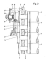
- the drive spur gear 17 of the plate cylinder 8 is in engagement with the drive spur gear 15 of the offset cylinder 6, the drive spur gear also being fastened here on the journal 18 of the plate cylinder 8 (FIG. 2).
- each printing unit take up the bearings for the cylinders and rollers.
- the plate cylinders 7, 8 inking units 20 and dampening units 21 are assigned.
- the two offset cylinders 5 and 6 can be pivoted in their bearings in such a way that they can be turned on and off against the two plate cylinders 7 and 8 and also against one another.
- An inclination of the plate cylinders can be carried out via the bearings of the plate cylinders.
- the bearings provided for this are not shown in the drawings.
- the drive spur gear 9 is also provided with a circumferential register adjustment, not shown, with which the two pairs of plate cylinders and offset cylinders can be rotated.
- the two main spur gears 10, 11 of the main drive are mounted on the side frame 19 via roller bearings 22 and journals 23.
- the diameters of the two main spur gears 10, 11 in the exemplary embodiment shown are approximately 540 mm and together correspond approximately to the spacing of the printing units 1, 2 and 2, 3. Since the arrangement thereof is not in alignment due to the design, the diameter does not exactly correspond to the spacing of the printing units from each other. The distance can be increased by increasing the diameter.
- a threaded pin 27 is rotatably provided, which axially shifts the drive spur gear 9 on a spline-shaft connection known per se and disengages from the main spur gear 10 of the main drive (dash-dotted position).
Landscapes
- Engineering & Computer Science (AREA)
- Mechanical Engineering (AREA)
- Rotary Presses (AREA)
- Inking, Control Or Cleaning Of Printing Machines (AREA)
Description
- Die Erfindung bezieht sich auf einen Hauptantrieb für Rollenrotations-Offsetdruckmaschinen mit Reihenanordnung der Gummi-Gummidruckwerke, die jeweils zwei zusammenwirkende Offsetzylinder aufweisen, die über je ein Stirnrad miteinander und dem Stirnrad des zugehörigen Plattenzylinders im Eingriff stehen, bei dem jedes Druckwerk als Antrieb zwei miteinander und jeweils mit den Hauptstirnrädern des benachbarten Druckwerkes kämmen, über Lagerzapfen am Seitengestell gelagerte Hauptstirnräder sehr hoher Fertigungsgenauigkeit aufweist, die in einer anderen Radflucht liegen als die Stirnräder der Platten- und Offsetzylinder.
- Ein bekannter Antrieb dieser Art (DE-OS 26 37 795) verwendet pro Druckwerk bereits zwei Hauptstirnräder, die in direktem Eingriff stehen. Jedes dieser Stirnräder kämmt mit je einem Antriebsstirnrad der beiden Plattenzylinder, wobei die Antriebsstirnräder der beiden Platten-Offsetzylinderpaare ebenfalls in Eingriff stehen können. Dieser bekannte Hauptantrieb, bei dem infolge dessen die Durchmesser der Hauptstirnräder festliegen, ermöglicht bereits einen optimal drehfehlerfreien spiel- und verschleißarmen Antrieb der Gummi-Gummidruckwerke, ist aber durch den doppelten Antrieb jedes Druckwerkes aufwendig und ermöglicht ohne besondere Justierung einen definierten Kraftfluß nur dann, wenn die Antriebsräder der beiden Gummizylinder nicht miteinander kämmen.
- Aufgabe der Erfindung ist es, einen solchen optimal drehfehlerfreien spiel- und verschleißarmen Hauptantrieb zu schaffen, bei dem die Hauptstirnräder mit beliebigem Durchmesser ausgebildet werden können, dessen technischer Aufbau vereinfacht ist und bei dem der definierte Kraftfluß in dem Antriebsrädern erhalten bleibt.
- Die Aufgabe wird dadurch gelöst, daß zur Einleitung der gesamten Antriebskraft in das jeweilige Druckwerk nur einem von den beiden Plattenzylindern eines jeden Druckwerkes ein Antriebsstirnrad zugeordnet ist, das mit einem der beiden Hauptstirnräder im Eingriff steht. Durch den erfindungsgemäßen Antrieb des Gummi-Gummidruckwerkes über nur ein Antriebsstirnrad wird ein vereinfachter Aufbau des Hauptantriebes erreicht. Auch läßt sich der Durchmesser der Hauptstirnräder frei festlegen, so daß der Abstand der Druckwerke an die Erfordernisse angepaßt werden kann. Der Antrieb wird ohne Verspannung der beteiligten Stirnräder durchgeführt und trotzdem wird immer ein definierter Kraftfluß innerhalb des Antriebes erreicht. Auch ist mit der beanspruchten Lösung die Schrägstellung der beiden Plattenzylinder pro Druckwerk erleichtert. Durch Wegfall der Verspannung können höhere Leistungen bei gleicher Dimensionierung der Antriebsräder übertragen werden
- Das Merkmal des Anspruchs 2 kennzeichnet eine weitere Vereinfachung des Stirnradantriebes, wobei sich besonders vorteilhaft erweist, daß zum Entkuppeln der Druckwerke nur eine Kupplung erforderlich ist gegenüber zwei Kupplungen mit gegenseitiger elektrischer Verriegelung bei einem Antrieb über 2 Plattenzylinder-Antriebsräder.
- Ein Ausführungsbeispiel der Erfindung ist in den Zeichnungen schematisch dargestellt. Es zeigt:
- Fig. 1 eine Seitenansicht eines Druckwerkes,
- Fig. 2 einen Teilquerschnitt durch den Antrieb.
- Das Ausführungsbeispiel gemäß Fig. 1 zeigt eine Rollenrotations-Offsetdruckmaschine, die aus den Druckwerken 1, 2 und 3 besteht. Durch diese wird etwa horizontal die Papierbahn 4 in Pfeilrichtung hindurchgeführt. Die Papierbahn 4 erhalten die Druckwerke von einem nicht dargestellten Rollenträger. Nach dem Bedrucken kann sie über ein Trockenaggregat. z.B. in einem Falzapparat, weiterverarbeitet werden. Bei der gezeigten Maschine handelt es sich um eine sogenannte Gummi-Gummimaschine, bei der jeweils die Papierbahn zwischen den Offsetzylindern 5, 6 hindurchgeführt und bedruckt wird.
- Jeder der beiden Offsetzylinder 5, 6 arbeitet mit einem Plattenzylinder 7, 8 zusammen. Dem oberen Plattenzylinder 7 ist im gezeigten Beispiel ein Antriebsstirnrad 9 zugeordnet, das mit dem Hauptstirnrad 10 des Hauptantriebes in Eingriff steht. In gleicher Weise könnte der Antrieb auch über den Plattenzylinder 8 erfolgen.
- Wie aus Fig. 1 ersichtlich, sind je Druckwerk zwei in Eingriff stehende Hauptstirnräder 10, 11 vorgesehen, die mit den Hauptstirnrädern des jeweils benachbarten Druckwerkes kämmen. Im gezeigten Ausführungsbeispiel steht somit das Hauptstirnrad 11 des Druckwerkes 1 mit dem Hauptstirnrad 10 von Druckwerk 2 in Eingriff, das wiederum mit dem Hauptstirnrad 11 kämmt. Die gleichen Eingriffsverhältnisse bestehen auch zwischen den Druckwerken 2 und 3, wobei ebenfalls das Hauptstirnrad 11 von Druckwerk 2 mit dem Hauptstirnrad 10 von Druckwerk 3 kämmt.
- Die Hauptstirnräder werden von einem nicht dargestellten Antriebsmotor angetrieben, wobei dieser Motor einem beliebigen Druckwerk zugeordnet werden kann.
- Neben den Hauptstirnrädern 10, 11 befindet sich in einer anderen Radflucht auf dem Achszapfen 12 des Plattenzylinders 7 ein Antriebsstirnrad 13, das den Plattenzylinder 7 über ein weiteres Stirnrad 14 mit dem Gummizylinder 5 koppelt. Die Antriebsstirnräder 14 und 15, die in Eingriff stehen, sind auf den Achszapfen 16 der beiden Offsetzylinder 5 und 6 angeordnet. Mit dem Antriebsstirnrad 15 des Offsetzylinders 6 steht das Antriebsstirnrad 17 des Plattenzylinders 8 in Eingriff, wobei auch hier das Antriebsstirnrad auf dem Achszapfen 18 des Plattenzylinders 8 befestigt ist (Fig. 2).
- Im gezeigten Ausführungsbeispiel gemäß Fig. 1 nehmen die Seitengestelle 19 jedes Druckwerkes die Lagerungen für die Zylinder und Walzen auf. Hierbei sind den Plattenzylindern 7, 8 Farbwerke 20 und Feuchtwerke 21 zugeordnet.
- Zum Druckan- und -abstellen sind die beiden Offsetzylinder 5 und 6 in ihren Lagerungen derart verschwenkbar, daß sie gegenüber den beiden Plattenzylindern 7 und 8 und auch gegeneinander an- bzw. abgestellt werden können. Über die Lagerungen der Plattenzylinder läßt sich eine Schrägstellung derselben durchführen. Die hierfür vorgesehenen Lagerungen sind in den Zeichnungen nicht dargestellt. Auch ist das Antriebsstirnrad 9 mit einer nicht dargestellten Umfangsregisterverstellung versehen, mit der die beiden Plattenzylinder-, Offsetzylinderpaare verdreht werden können.
- Die beiden Hauptstirnräder 10, 11 des Hauptantriebes sind über Rollenlager 22 und Lagerzapfen 23 am Seitengestell 19 gelagert. Die Durchmesser der beiden Hauptstirnräder 10, 11 betragen im gezeigten Ausführungsbeispiel etwa 540 mm und entsprechen zusammen etwa dem Abstand der Druckwerke 1, 2 bzw. 2, 3. Da die Anordnung derselben konstruktionsbedingt nicht in einer Flucht erfolgt, entspricht der Durchmesser nicht genau dem Abstand der Druckwerke voneinander. Durch Vergrößerung der Durchmesser läßt sich der Abstand vergrößern.
- Über Stehbolzen 24 ist am Seitengestell 19 ein Schild 25 gelagert, das einen Gewindeflansch 26 trägt. In diesem ist ein Gewindezapfen 27 drehbar vorgesehen, der über eine Kupplung 28 das Antriebsstirnrad 9 auf einer an sich bekannten Keil-Wellenverbindung axial verschiebt und aus dem Hauptstirnrad 10 des Hauptantriebes ausrückt (strichpunktiert gezeichnete Stellung). Durch das Ausrücken des Antriebsstirnrades 9 werden die Plattenzylinder 7, und die Offsetzylinder 5, mit den dazugehörigen Farb-20 und Feuchtwerken 21 stillgesetzt.
Claims (2)
Priority Applications (1)
| Application Number | Priority Date | Filing Date | Title |
|---|---|---|---|
| AT82101786T ATE26421T1 (de) | 1981-03-31 | 1982-03-06 | Hauptantrieb fuer rotations-offsetdruckmaschinen. |
Applications Claiming Priority (2)
| Application Number | Priority Date | Filing Date | Title |
|---|---|---|---|
| DE8109472U | 1981-03-31 | ||
| DE19818109472U DE8109472U1 (de) | 1981-03-31 | 1981-03-31 | "hauptantrieb fuer rotations-offsetdruckmaschinen" |
Publications (2)
| Publication Number | Publication Date |
|---|---|
| EP0061606A1 EP0061606A1 (de) | 1982-10-06 |
| EP0061606B1 true EP0061606B1 (de) | 1987-04-08 |
Family
ID=6726283
Family Applications (1)
| Application Number | Title | Priority Date | Filing Date |
|---|---|---|---|
| EP82101786A Expired EP0061606B1 (de) | 1981-03-31 | 1982-03-06 | Hauptantrieb für Rotations-Offsetdruckmaschinen |
Country Status (11)
| Country | Link |
|---|---|
| EP (1) | EP0061606B1 (de) |
| JP (2) | JPS57167265A (de) |
| AR (1) | AR230966A1 (de) |
| AT (1) | ATE26421T1 (de) |
| CA (1) | CA1257501A (de) |
| DE (2) | DE8109472U1 (de) |
| DK (1) | DK148820C (de) |
| ES (1) | ES272000Y (de) |
| MX (1) | MX155190A (de) |
| NO (1) | NO156749C (de) |
| ZA (1) | ZA82445B (de) |
Cited By (2)
| Publication number | Priority date | Publication date | Assignee | Title |
|---|---|---|---|---|
| DE4226392C1 (de) * | 1992-08-10 | 1993-11-11 | Roland Man Druckmasch | Sicherheitseinrichtung zum Einkoppeln von Zahnrädern unterschiedlicher Gestellteile einer Rotationsdruckmaschine |
| DE4219969A1 (de) * | 1992-06-19 | 1993-12-23 | Koenig & Bauer Ag | Antrieb für eine Mehrfarben-Rollenrotationsdruckmaschine |
Families Citing this family (1)
| Publication number | Priority date | Publication date | Assignee | Title |
|---|---|---|---|---|
| DE29522321U1 (de) | 1995-10-27 | 2001-09-27 | Man Roland Druckmaschinen Ag, 63069 Offenbach | Antrieb für ein Druckwerk |
Family Cites Families (4)
| Publication number | Priority date | Publication date | Assignee | Title |
|---|---|---|---|---|
| US2180782A (en) * | 1936-06-09 | 1939-11-21 | Wood Newspaper Mach Corp | Rotary printing press |
| DE2637795C2 (de) * | 1976-08-21 | 1981-12-24 | Heidelberger Druckmaschinen Ag, 6900 Heidelberg | Hauptantrieb für Rollenrotations-Offsetdruckmaschinen |
| JPS5527853A (en) * | 1978-08-18 | 1980-02-28 | Mitsui Toatsu Chemicals | Manufacture of binder for refractories and composition therefor |
| FR2458395A1 (fr) * | 1979-06-08 | 1981-01-02 | Creusot Loire | Dispositif de commande des cylindres d'une machine d'imprimerie offset |
-
1981
- 1981-03-31 DE DE19818109472U patent/DE8109472U1/de not_active Expired
-
1982
- 1982-01-22 ZA ZA82445A patent/ZA82445B/xx unknown
- 1982-02-17 MX MX191434A patent/MX155190A/es unknown
- 1982-02-19 AR AR288488A patent/AR230966A1/es active
- 1982-02-26 CA CA000397246A patent/CA1257501A/en not_active Expired
- 1982-03-05 JP JP57034146A patent/JPS57167265A/ja active Pending
- 1982-03-06 DE DE8282101786T patent/DE3275987D1/de not_active Expired
- 1982-03-06 EP EP82101786A patent/EP0061606B1/de not_active Expired
- 1982-03-06 AT AT82101786T patent/ATE26421T1/de not_active IP Right Cessation
- 1982-03-08 ES ES1982272000U patent/ES272000Y/es not_active Expired
- 1982-03-11 DK DK107782A patent/DK148820C/da not_active IP Right Cessation
- 1982-03-30 NO NO821063A patent/NO156749C/no unknown
-
1985
- 1985-07-30 JP JP1985116023U patent/JPS6145134U/ja active Pending
Cited By (2)
| Publication number | Priority date | Publication date | Assignee | Title |
|---|---|---|---|---|
| DE4219969A1 (de) * | 1992-06-19 | 1993-12-23 | Koenig & Bauer Ag | Antrieb für eine Mehrfarben-Rollenrotationsdruckmaschine |
| DE4226392C1 (de) * | 1992-08-10 | 1993-11-11 | Roland Man Druckmasch | Sicherheitseinrichtung zum Einkoppeln von Zahnrädern unterschiedlicher Gestellteile einer Rotationsdruckmaschine |
Also Published As
| Publication number | Publication date |
|---|---|
| DE3275987D1 (en) | 1987-05-14 |
| ES272000Y (es) | 1984-05-16 |
| DE8109472U1 (de) | 1981-08-13 |
| NO821063L (no) | 1982-10-01 |
| ATE26421T1 (de) | 1987-04-15 |
| DK148820C (da) | 1986-06-02 |
| NO156749B (no) | 1987-08-10 |
| CA1257501A (en) | 1989-07-18 |
| AR230966A1 (es) | 1984-08-31 |
| DK107782A (da) | 1982-10-01 |
| ES272000U (es) | 1983-11-16 |
| JPS57167265A (en) | 1982-10-15 |
| NO156749C (no) | 1987-11-18 |
| JPS6145134U (ja) | 1986-03-25 |
| ZA82445B (en) | 1982-12-29 |
| EP0061606A1 (de) | 1982-10-06 |
| DK148820B (da) | 1985-10-14 |
| MX155190A (es) | 1988-02-01 |
Similar Documents
| Publication | Publication Date | Title |
|---|---|---|
| EP0919372B2 (de) | Druckwerk für eine Rotationsdruckmaschine | |
| DE2436199C2 (de) | Rotations-Offset-Druckmaschine | |
| DE4021895C2 (de) | Druckeinheit einer Offsetdruckmaschine zur Durchführung eines fliegenden Druckplattenwechsels | |
| DE19911180C2 (de) | Druckwerk für eine Rotationsdruckmaschine | |
| DE2637795C2 (de) | Hauptantrieb für Rollenrotations-Offsetdruckmaschinen | |
| EP0324140B1 (de) | Farbwerk | |
| DE4228610A1 (de) | Papierführung bei Rollenrotationsdruckmaschinen | |
| EP0061606B1 (de) | Hauptantrieb für Rotations-Offsetdruckmaschinen | |
| DE19535266A1 (de) | Kurzfarbwerk | |
| DE3125434A1 (de) | Vorrichtung zum zufuehren von farbe an die druckplatte einer druckmaschine | |
| EP0615841B1 (de) | Druckmaschine | |
| CH658222A5 (de) | Rotationsdruckmaschine in reihenbauweise. | |
| DE3429079A1 (de) | Rollenrotations-offsetdruckmaschine | |
| CH625747A5 (en) | Printing unit of an offset printing machine having a device for inking a numbering cylinder | |
| DE2553768B2 (de) | Rollen-Rotationsdruckmaschine | |
| DE19848390B4 (de) | Rollenrotationsdruckmaschine für einen schnellen Produktionswechsel | |
| DE4402703A1 (de) | Druckwerk mit Mechanismus für Farbreibwalzen | |
| DD279851A1 (de) | Antrieb fuer farbwerke | |
| DE2754429C2 (de) | Rollen-Rotations-Offsetdruckmaschine, bei welcher zwei Druckwerkszylinder über einen Torsionsstab miteinander in Verbindung stehen | |
| CH686426A5 (de) | Druckpresse mit aneinander anstellbaren Drucktuchzylindern. | |
| DE4140651C2 (de) | Feuchtauftragwalzenantrieb in Druckmaschinen | |
| DE19755317A1 (de) | Bahnführungswalze | |
| EP0066114A1 (de) | Verreibwalzenantrieb am Farbwerk von Offset-Rotationsdruckmaschinen | |
| DE3523331C2 (de) | ||
| DE2609441C2 (de) | Einrichtung zur Umstellung einer Rollenrotationsdruckmaschine von Offsetdruck auf Hochdruck |
Legal Events
| Date | Code | Title | Description |
|---|---|---|---|
| PUAI | Public reference made under article 153(3) epc to a published international application that has entered the european phase |
Free format text: ORIGINAL CODE: 0009012 |
|
| AK | Designated contracting states |
Designated state(s): AT BE CH DE FR GB IT NL SE |
|
| 17P | Request for examination filed |
Effective date: 19830127 |
|
| GRAA | (expected) grant |
Free format text: ORIGINAL CODE: 0009210 |
|
| AK | Designated contracting states |
Kind code of ref document: B1 Designated state(s): AT BE CH DE FR GB IT LI NL SE |
|
| REF | Corresponds to: |
Ref document number: 26421 Country of ref document: AT Date of ref document: 19870415 Kind code of ref document: T |
|
| REF | Corresponds to: |
Ref document number: 3275987 Country of ref document: DE Date of ref document: 19870514 |
|
| ET | Fr: translation filed | ||
| ITF | It: translation for a ep patent filed | ||
| PLBE | No opposition filed within time limit |
Free format text: ORIGINAL CODE: 0009261 |
|
| STAA | Information on the status of an ep patent application or granted ep patent |
Free format text: STATUS: NO OPPOSITION FILED WITHIN TIME LIMIT |
|
| 26N | No opposition filed | ||
| ITTA | It: last paid annual fee | ||
| PGFP | Annual fee paid to national office [announced via postgrant information from national office to epo] |
Ref country code: AT Payment date: 19920227 Year of fee payment: 11 |
|
| PGFP | Annual fee paid to national office [announced via postgrant information from national office to epo] |
Ref country code: BE Payment date: 19920310 Year of fee payment: 11 |
|
| PGFP | Annual fee paid to national office [announced via postgrant information from national office to epo] |
Ref country code: SE Payment date: 19920316 Year of fee payment: 11 |
|
| PGFP | Annual fee paid to national office [announced via postgrant information from national office to epo] |
Ref country code: NL Payment date: 19920331 Year of fee payment: 11 |
|
| PGFP | Annual fee paid to national office [announced via postgrant information from national office to epo] |
Ref country code: CH Payment date: 19920430 Year of fee payment: 11 |
|
| PGFP | Annual fee paid to national office [announced via postgrant information from national office to epo] |
Ref country code: GB Payment date: 19930222 Year of fee payment: 12 |
|
| PGFP | Annual fee paid to national office [announced via postgrant information from national office to epo] |
Ref country code: FR Payment date: 19930305 Year of fee payment: 12 |
|
| PG25 | Lapsed in a contracting state [announced via postgrant information from national office to epo] |
Ref country code: AT Effective date: 19930306 |
|
| PG25 | Lapsed in a contracting state [announced via postgrant information from national office to epo] |
Ref country code: SE Effective date: 19930307 |
|
| PG25 | Lapsed in a contracting state [announced via postgrant information from national office to epo] |
Ref country code: LI Effective date: 19930331 Ref country code: CH Effective date: 19930331 Ref country code: BE Effective date: 19930331 |
|
| BERE | Be: lapsed |
Owner name: HEIDELBERGER DRUCKMASCHINENE A.G. Effective date: 19930331 |
|
| PG25 | Lapsed in a contracting state [announced via postgrant information from national office to epo] |
Ref country code: NL Effective date: 19931001 |
|
| NLV4 | Nl: lapsed or anulled due to non-payment of the annual fee | ||
| REG | Reference to a national code |
Ref country code: CH Ref legal event code: PL |
|
| PG25 | Lapsed in a contracting state [announced via postgrant information from national office to epo] |
Ref country code: GB Effective date: 19940306 |
|
| PGFP | Annual fee paid to national office [announced via postgrant information from national office to epo] |
Ref country code: DE Payment date: 19940415 Year of fee payment: 13 |
|
| GBPC | Gb: european patent ceased through non-payment of renewal fee |
Effective date: 19940306 |
|
| PG25 | Lapsed in a contracting state [announced via postgrant information from national office to epo] |
Ref country code: FR Effective date: 19941130 |
|
| REG | Reference to a national code |
Ref country code: FR Ref legal event code: ST |
|
| EUG | Se: european patent has lapsed |
Ref document number: 82101786.0 Effective date: 19931008 |
|
| PG25 | Lapsed in a contracting state [announced via postgrant information from national office to epo] |
Ref country code: DE Effective date: 19951201 |