EP0061184A2 - Procédé de fabrication d'aiguilles de machines à coudre - Google Patents
Procédé de fabrication d'aiguilles de machines à coudre Download PDFInfo
- Publication number
- EP0061184A2 EP0061184A2 EP82102324A EP82102324A EP0061184A2 EP 0061184 A2 EP0061184 A2 EP 0061184A2 EP 82102324 A EP82102324 A EP 82102324A EP 82102324 A EP82102324 A EP 82102324A EP 0061184 A2 EP0061184 A2 EP 0061184A2
- Authority
- EP
- European Patent Office
- Prior art keywords
- section
- needle
- cross
- flat
- piston
- Prior art date
- Legal status (The legal status is an assumption and is not a legal conclusion. Google has not performed a legal analysis and makes no representation as to the accuracy of the status listed.)
- Granted
Links
- 238000004519 manufacturing process Methods 0.000 title claims abstract description 20
- 239000000463 material Substances 0.000 claims abstract description 32
- 238000003825 pressing Methods 0.000 claims abstract description 27
- 238000009958 sewing Methods 0.000 claims abstract description 18
- 238000000748 compression moulding Methods 0.000 claims abstract description 15
- 239000013067 intermediate product Substances 0.000 claims abstract description 5
- 238000000034 method Methods 0.000 claims description 21
- 238000004080 punching Methods 0.000 claims description 15
- 238000009966 trimming Methods 0.000 claims description 7
- 230000007704 transition Effects 0.000 claims description 5
- 238000000926 separation method Methods 0.000 claims description 4
- 238000003780 insertion Methods 0.000 claims description 2
- 230000037431 insertion Effects 0.000 claims description 2
- 230000015572 biosynthetic process Effects 0.000 description 7
- 230000008569 process Effects 0.000 description 5
- 230000009467 reduction Effects 0.000 description 5
- 238000013459 approach Methods 0.000 description 4
- 230000008901 benefit Effects 0.000 description 4
- 239000007858 starting material Substances 0.000 description 4
- 238000005520 cutting process Methods 0.000 description 3
- 238000006073 displacement reaction Methods 0.000 description 3
- 238000004049 embossing Methods 0.000 description 3
- 230000000087 stabilizing effect Effects 0.000 description 3
- 239000002699 waste material Substances 0.000 description 3
- PXHVJJICTQNCMI-UHFFFAOYSA-N Nickel Chemical compound [Ni] PXHVJJICTQNCMI-UHFFFAOYSA-N 0.000 description 2
- 230000006835 compression Effects 0.000 description 2
- 238000007906 compression Methods 0.000 description 2
- 238000013461 design Methods 0.000 description 2
- 238000011161 development Methods 0.000 description 2
- 230000018109 developmental process Effects 0.000 description 2
- 230000000694 effects Effects 0.000 description 2
- 230000002349 favourable effect Effects 0.000 description 2
- 238000010438 heat treatment Methods 0.000 description 2
- 230000006641 stabilisation Effects 0.000 description 2
- 238000011105 stabilization Methods 0.000 description 2
- 210000001015 abdomen Anatomy 0.000 description 1
- 230000009471 action Effects 0.000 description 1
- 238000005452 bending Methods 0.000 description 1
- 230000008859 change Effects 0.000 description 1
- 230000006378 damage Effects 0.000 description 1
- 238000005246 galvanizing Methods 0.000 description 1
- 238000000227 grinding Methods 0.000 description 1
- 238000007689 inspection Methods 0.000 description 1
- 230000003993 interaction Effects 0.000 description 1
- 238000003801 milling Methods 0.000 description 1
- 229910052759 nickel Inorganic materials 0.000 description 1
- 238000007747 plating Methods 0.000 description 1
- 238000005498 polishing Methods 0.000 description 1
- 239000000047 product Substances 0.000 description 1
- 230000000717 retained effect Effects 0.000 description 1
- 238000005096 rolling process Methods 0.000 description 1
- 238000007493 shaping process Methods 0.000 description 1
- 239000004753 textile Substances 0.000 description 1
- 230000003313 weakening effect Effects 0.000 description 1
Images


Classifications
-
- B—PERFORMING OPERATIONS; TRANSPORTING
- B21—MECHANICAL METAL-WORKING WITHOUT ESSENTIALLY REMOVING MATERIAL; PUNCHING METAL
- B21G—MAKING NEEDLES, PINS OR NAILS OF METAL
- B21G1/00—Making needles used for performing operations
- B21G1/02—Making needles used for performing operations of needles with eyes, e.g. sewing-needles, sewing-awls
-
- D—TEXTILES; PAPER
- D05—SEWING; EMBROIDERING; TUFTING
- D05B—SEWING
- D05B85/00—Needles
-
- B—PERFORMING OPERATIONS; TRANSPORTING
- B21—MECHANICAL METAL-WORKING WITHOUT ESSENTIALLY REMOVING MATERIAL; PUNCHING METAL
- B21G—MAKING NEEDLES, PINS OR NAILS OF METAL
- B21G1/00—Making needles used for performing operations
- B21G1/02—Making needles used for performing operations of needles with eyes, e.g. sewing-needles, sewing-awls
- B21G1/04—Making needles used for performing operations of needles with eyes, e.g. sewing-needles, sewing-awls of needles specially adapted for use in machines or tools
-
- Y—GENERAL TAGGING OF NEW TECHNOLOGICAL DEVELOPMENTS; GENERAL TAGGING OF CROSS-SECTIONAL TECHNOLOGIES SPANNING OVER SEVERAL SECTIONS OF THE IPC; TECHNICAL SUBJECTS COVERED BY FORMER USPC CROSS-REFERENCE ART COLLECTIONS [XRACs] AND DIGESTS
- Y10—TECHNICAL SUBJECTS COVERED BY FORMER USPC
- Y10T—TECHNICAL SUBJECTS COVERED BY FORMER US CLASSIFICATION
- Y10T29/00—Metal working
- Y10T29/49—Method of mechanical manufacture
- Y10T29/49789—Obtaining plural product pieces from unitary workpiece
- Y10T29/49792—Dividing through modified portion
Definitions
- the invention relates to a method for producing sewing machine needles from a cylindrical wire section by compression molding, in which, starting from a wire section diameter corresponding to the thickness of the needle piston, the wire section is reduced to at least the final cross-sectional dimension over at least the length of the needle shaft and the shoulder , furthermore, in the region of the needle shaft, the thread grooves are pressed in from the curved outer surfaces of the wire section.
- the blank is reduced in cross section - bswp. in a so-called circulation press (DE-OS 19 52 152).
- This operation is relatively complex and considerably increases the cost of a precision part such as a sewing machine needle.
- the strong noise generation has a disruptive effect on production due to the tappet action, which tappet axially "kneads" the material of the blank. This cold stretching over a considerable length often has a disadvantageous effect on the material structure.
- the needle shaft and attachment are brought into a flat, round cross-section by pressing or rolling and the thread grooves are pressed in from the curved surface areas.
- the object of the invention is to provide an optimal needle manufacturing method, which is particularly suitable for double needle production. should be suitable, with a simple tool can manage with only a fraction of the stroke distance and thus achieve a high degree of economy.
- an economically viable, extremely economical machine needle manufacturing process is achieved: the reduction in cross-section up to the partial pre-compression of the needle shaft and shoulder takes place on the full material cross-section, displacing the excess blank material in opposite, laterally protruding flat whiskers.
- the entire raw shape of the needle can be produced with an extremely short press stroke.
- the blank material that is displaced when troughs are formed also moves in the shortest possible direction towards the flat beards when the needle troughs are pressed.
- the continuous run down to the eye area provides an advantageous centering for the protrusion of the tool punching the eye of the needle.
- the flat beards can be removed when punching the eye of the needle, ie in the punching end phase.
- the beards that arise on both sides of the blank axis can be used as a guide and holding surface in connection can be used with the individual process steps.
- the basically very small blank can be mastered well using this fact.
- the basic shape is roughly boat-shaped.
- the fillet between the two diametrically opposite, convex lateral surfaces and the subsequent broad beard surface also offers a favorable, self-centering cutting edge orientation.
- the shaft cross section is not supported in the area of the radial flow direction of the flat whiskers by the shaping upper and lower die part, so that there is an adapted free exit of the excess material. This also prevents stresses in the material.
- An advantageous development with the aim of high economic efficiency and optimal material utilization consists in that an intermediate section formed by the flat whiskers remains between the tips of the needles of a double needle blank which are arranged at a distance from one another and face one another.
- the intermediate section thus formed by the flat beards already present creates a kind of bridge between the two needles. This bridge also stabilizes the tip area of the two needles. In addition, the tip area can be safely grasped, determined and controlled.
- the intermediate section provides enough space for the provision of a fitting hole for the interaction with a fitting pin which is seated on the tool.
- a sequence of steps that is particularly gentle on the material and tools is given if, after the flat beards have been cut off when pressing the eye section and pressing the needle tip and pressing the needle shaft groove, again laterally protruding beard-like approaches in the tip-side end area are pressed, which are attached to the Connect the intermediate section, further a throat is formed, whereupon the blank receives its eye of the needle, followed by a sinking from this side and then turning the blank over in the press tool to cause the needle eye to be lowered on the other side, followed by pressing and trimming the tip, and the separation of the approaches together with the intermediate section.
- the intermediate section formed by the remaining sections of the flat beards is also for turning the blank over useful. In terms of material, the latter can even be used for tip formation.
- an intermediate product which has two convex lateral surfaces of a core cross-section that are approximately the same as the nominal size of the needle shaft, opposite each other in mirror image, from which laterally protruding flat whiskers originate, the total material cross-section of which corresponds approximately to the difference between the piston cross-section and the core cross-section.
- the flat whiskers can also be used in a cost-effective way to achieve high resistance to bending load forces acting on the needle shaft.
- the transition area between shoulder and shaft is particularly prone to breakage.
- two diametrically opposed wings are provided in the transition area between the shoulder and the needle shaft, which remain as beard sections when the flat beards are separated.
- the back of the wing is convex, the plane of the wing lies transversely to the direction of the eye of the needle and the wing extends over the full length of the shoulder and to approximately the same extent over the initial length of the needle shaft.
- the wings always fall due to the material, which is always smaller in cross-section.
- the notch zone which forms a possible breaking point, even if it is very obtuse, between the frustoconical taper of the shoulder and the shaft is highly stabilized by the wings.
- the latter act as stiffening ribs. Due to their diametrical arrangement, they are also far enough away from any piston flattening provided in household sewing machine needles. They can also be produced with sufficient material thickness.
- the wings also do not stand in the way of the flattening mentioned, since they do not protrude above them; it is possible to mark such flats therefore always perform without disabilities.
- the measure that the back of the wings formed by the flat beard remains curved convexly prevents protruding injuries or hooking with the textile material.
- the outer wing edges and inside corners can be rounded transversely. Taking into account the direction of loading when sewing, it is advantageous that the plane of the wings is transverse to the direction of the eye of the needle. Optimal stability results in a simple manner in that the wings extend over the full length of the extension and to approximately the same extent over the initial length of the needle shaft.
- compression molding also offers special options with regard to piston formation and, for this purpose, finally, in a production-advantageous manner, proposes the method steps that, starting from a cross-sectional diameter that is smaller than the final diameter of the piston section, the flattening is pressed while increasing the cross-sectional diameter in the remaining circular cross-sectional area, and then a longitudinal groove starting from the flattening is pressed into the piston section of such size that the material displaced in this compression molding brings the round cross section of the piston section to its nominal size.
- This makes it possible to produce a fitting piston contour, although a much thinner wire is assumed, for example for the production of thinner needles.
- tolerance compensation The assignment precision can be maintained as with classic, but more elaborately produced needles.
- the reduction in load-bearing surface resulting from the formation of the longitudinal channel has no disadvantages, since the remaining surfaces of the flattened area retain their maximum width limitation. These remaining areas bear equally well.
- the U or V profile that is now also present in the piston proves to be an additional stabilizing factor.
- the longitudinal channel created in the area of the flattening is not on the same side of the The needle body lies like the long thread groove; it is also axially offset.
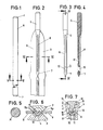
- the blank for sewing machine needle manufacture is formed by a wire section A cut to length. This has a circular cross-section. Its diameter corresponds approximately to that of the cylindrical needle piston 1. Both ends of the wire section are chamfered at 1 '. The total length of this wire section A corresponds to the material requirement for the simultaneous production of two sewing machine needles.
- This wire section A is placed in a pressing tool, the upper die of which is denoted by 2 and the lower die of which is denoted by 3.
- the Tool is equipped in such a way that, in addition to punching the eye section ⁇ , the final needle shape is produced with a press stroke by reducing the cross-section.
- the blank then has the usual flattening 4 in the area of its piston 1 and the adjoining frustoconical extension 5. The latter merges into the needle shaft 6, which ends in a needle tip 7.
- the usual fillet 6 ' is also taken into account on the piston side of the eye section.
- the needle shaft 6 takes the form of a V-profile as a result of the simultaneous pressing in of a needle groove 8 extending from the shoulder 5 to the tip region.
- the blank material displaced due to the reduction in cross-section and channel formation emerges through a tool gap Sp left on both sides between the upper and lower dies 2, 3.
- the flat beards that form are designated by 9. Their width depends on the displacement volume. Less material is displaced in the area of the neck 5 than in the tip area.
- the flat beards 9 bring a flat strip-like width enlargement of the blank which is advantageous for the next method step; it is many times larger in area and can therefore be gripped better and brought into the next tool station and centered there in the correct position.
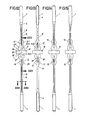
- the punching of the needle eye 10 then takes place in this tool station.
- the blank is held by its flat beards 9 between the jaws of a separating device V.
- the needle shaft 6 itself lies in a lower punch 11 with a perforated window 12.
- the associated upper punch 13 has a punching projection 14.
- the punching projection 14 runs from above into the centering groove 8 which is V-shaped in cross-section and rounded in its V-apex.
- the two flat beards 9 are cut off at the same time, in the present case sheared off by the jaws of the separation device V then being carried along by the upper punch moving downward relative to the lower punch 11 which remains.
- the corresponding Time delay is achieved by switching on an clearance x between the upper punch 13 and the upper jaw of the separating device. Only when the two shoulders 15 located to the side of the punching projection, offset in height from it, step onto the corresponding shoulders 16 of the upper jaw of the separating device, are the jaws acting as scissors displaced in the sense of separating the flat beards 9.
- the upper punch 13 can be held high by springs.
- the springs are not shown in detail.
- the ear edges can already be rounded.
- the tip 7 After rounding the eye edges, the tip 7 takes on its final shape, either as a rounded tip or as a pointed tip. After finishing, the usual treatment phases follow, such as heat treatment, polishing, galvanizing and finally the final inspection.
- the formation of two sewing machine needles is divided into a larger sequence of steps.
- the pistons 1 are left or formed in a first station of a clock-controlled follow-up tool at the free ends of the wire section A.
- the piston-forming end region is correspondingly provided with a flat 4 (FIG. 9).
- a marking or indication of origin can already be made by means of embossing.
- the blank reaches the second station from the first station in which the flattening 4 is produced (FIG. 10).
- the compression molding takes place in such a way that the displaced material in the area of the extension 5 and the needle shaft 6 to be formed into the joint between the upper and lower dies of the tool (not shown here) evades.
- the cross-section reduction on the two opposite wire material cross-sections creates the laterally protruding flat beards 9, which project freely as wings from the circular needle shaft and shoulder cross-section formed in the process. Reference is made to the sectional illustration in FIG. 21.
- the approach 5 has the shape of a truncated cone.
- the wider base faces the piston 1.
- the illustration in FIG. 10 already shows, as far as the extension 5 and shaft 6 are concerned, the final contour like a relief of the needles to be formed.
- the diametrically rooted flat whiskers 9 allow the transversely convex lateral surfaces M of extension 5 and shaft 6 to stand between them.
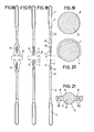
- the blank is now trimmed in the third station (FIG. 11).
- the shaft 6 is given the cross-sectional shape according to FIG. 22.
- the flat, vertical separating cut surfaces are pressed into a curve during channel pressing if this is provided in terms of shape (free spaces in the die).
- the trimming takes place in such a way that the flat whiskers 9 are removed or severed over a length section which corresponds approximately to that of the end length of the needle shaft 6, except for an intermediate section 9 'which is beyond the needle tips 7 to be formed.
- two diametrically opposed wings F remain as material residue, which, like the previously formed mustaches 9, extend parallel to the flattening 4.
- the remaining intermediate section 9 ' has the shape of a rectangular plate with the longer side oriented transversely to the blank axis. Its edge 9 "can be used to limit the stop.
- the long needle groove 8, the eye portion ⁇ extending from the attachment 5 to the tip region, and the pre-pressing of the tip 7 to be formed are molded.
- the shaft 6 of the sewing machine needle takes the shape shown in FIG. 23 shown truncated V-shaped cross-sectional shape. But also other cross-sectional shapes can be achieved, round, square, polygon etc.
- the needle groove 8 is symmetrical.
- the V-tip like the V-leg ends, is convexly rounded.
- the channel bottom however, has a concave fillet that essentially corresponds to the thread cross-section. Material is again displaced when pressing the eye section ⁇ and pre-pressing the needle tip.
- wing-like projections 9 projecting sideways on both sides, which together have approximately the outline of a sound body of known stringed instruments, the larger belly section being directly adjacent to the remaining intermediate section 9', ie immediately adjoins this.
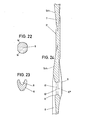
- the tip-forming part of the compression molding here consists of flattening the tip area, starting from the general shaft diameter. This creates a roof-shaped, wedge-shaped bevel Sch, which slopes down on both sides to the level of the intermediate section 9 'which is also further flattened and remains. During this pressing process, the circular needle shaft section 6 "disappears there. The intermediate piece 9 'widens somewhat as a result.
- the intermediate piece 9' which is now completely flattened, can have a fitting hole L as a centering aid or additional alignment aid for the edge edges 9" (FIG. 12, dot-dash line) Circle), which interacts with a dowel pin of the tool.
- the so-called fillet 6 ' which extends on the side of the needle shaft 6 opposite the needle groove 8, has already been pressed in the region of the eye portion ⁇ .
- This also includes the simultaneous formation of the short channel 17.
- the eye itself is not yet perforated. It is only pre-embossed and already marked as a bottleneck with 10 in FIGS. 12 and 13 for easier understanding.
- the depth of the embossing is indicated in FIG. 24 by the lines 10 ′ and 10 ′′ representing the embossing reason at this stage.
- the hole in the eye 10 is only punched in the fifth station of the tool (FIG. 14).
- the ear-forming area is completely pierced. This can be done extremely precisely, since the entire tip area can be positioned and held firmly by the remaining intermediate section 9 'of the flat beards 9 and also by the additional lugs 9' ''.
- the lugs 9 "'standing transversely to the perforation direction on the side flanks of the needle shaft practically form a kind of lateral stabilizing rib, which effectively prevent an undesired change in shape in the area of the ear area.
- the eye is lowered from one side of the needle (Fig. 15).
- the sinking takes place from the other side. Sinking is to be understood as the so-called rounding of the edges R of the eye hole which have a sharp ridge.
- This station (Fig. 17) is reserved for trimming the tip 7.
- the tip is already flattened on both sides in the plane of the V-axis.
- a flattening which is also roof-shaped or wedge-shaped is cut perpendicular to it.
- the cutting lines are designated 7 '.
- a kind of pyramid tip with a square outline or cross section is achieved.
- the waste piece shown in FIG. 17, consisting of the intermediate piece 9 'and, if appropriate, the lugs 9111, is shown in dash-dotted lines.
- the blank produced - taking into account the double-needle manufacturing process in the manner described is two blanks - is passed on for further treatment, such as heat treatment, surface grinding, nickel plating, searching and straightening.
- the intermediate product shown in FIGS. 2, 6 and 10, 21 has two lateral surfaces M of a core cross-section K (approximately shaft or shoulder cross-section) lying approximately in the nominal dimension of the needle shaft 6, mirror-inverted opposite one another, of which the laterally protruding flat whiskers 9 going out.
- Their total material cross section B 1 and B 2 corresponds to the difference between the piston cross section Q (FIG. 19) and the core cross section K.
- the transverse displacement of the materials can be driven so far that practically 90% of the needle surface - distributed over the top and bottom of the blank - is already available as a finished deformation due to a press stroke.
- the wings F ' are cut free so that they extend to form a stabilizing rib over the full length y of the extension 5 and to approximately the same extent over the initial length z of the needle shaft 6.
- the length z corresponds approximately to twice the shaft diameter.
- the back 18 of the wings F ' is convexly curved, in such a way that the greatest rib width is in the area of the angular groove K between the needle shaft 6 and the shoulder 5.
- the curvature is even; the back ends merge into the shaft 6 or the piston 1 at an obtuse angle. This prevents any entanglement zones.
- the area width or size of both wings F 'together corresponds approximately to the area dimension of the flat 4.
- the thickness of the wings corresponds to approximately half the needle shaft diameter, but at least one third of this diameter.
- Compression molding be it in the case of double-needle manufacture or single-needle manufacture, can also be used advantageously for a special piston design.
- a wire section of circular cross-section serves as the starting material. Its cross-sectional diameter d is smaller than the final diameter D of the piston section on the finished product.
- the blank described above initially receives the flattening 4 in the region of the piston section. This is produced by compression molding. This increases due to the displacement of the circular section-shaped material mass 1111 into the piston-forming material main mass 1 " the piston diameter. Reference is made to Fig. 31. The enlarged diameter of the piston section in this intermediate phase is indicated by d '. The circumferential area remaining with respect to the flat 4 retains its circular cross-sectional shape, albeit enlarged. The tool of this intermediate station is contoured accordingly. The joint between the upper and lower dies is such that there is no pinching of the needle body.
- a longitudinal groove 19 starting from the flattened portion 4 is pressed into the piston section.
- This longitudinal groove extends into the shoulder 5, but does not overlap the thread groove 8, which also starts in the shoulder 5.
- the material mass which is now further displaced by the longitudinal groove 19 merges into the main mass 1 "and causes a further enlargement of the piston diameter in this compression molding, namely until the desired nominal dimension is reached. This corresponds to the cross-sectional diameter D of the piston 1 of the finished sewing machine needle.
- the longitudinal groove 19 is symmetrical and leads to a type of U or V profile of the piston 1.
- the surface area width B generated in the intermediate phase is retained, as can be seen in Fig. 32.
- the longitudinal channel base 20 is rounded.
- the transition to the end faces 4 'and 4 "of the U and V legs also takes place via curves 21, which are convex, however.
- the flattened edge 22 merges into the round cross-sectional area or cylindrical piston skirt 23.
- the two parallel orientation lines 24 particularly visually illustrate the deformation process.
- Channel walls 25 diverge upwards, whereby the tool projection forming the longitudinal channel 19 can be lifted without jamming.
- Channel shape and channel depth can vary taking into account the diameter of the starting material and the desired nominal size.
Landscapes
- Engineering & Computer Science (AREA)
- Mechanical Engineering (AREA)
- Textile Engineering (AREA)
- Sewing Machines And Sewing (AREA)
Priority Applications (1)
| Application Number | Priority Date | Filing Date | Title |
|---|---|---|---|
| AT82102324T ATE13824T1 (de) | 1981-03-25 | 1982-03-20 | Verfahren zur herstellung von naehmaschinennadeln. |
Applications Claiming Priority (8)
| Application Number | Priority Date | Filing Date | Title |
|---|---|---|---|
| DE3111632 | 1981-03-25 | ||
| DE3111632 | 1981-03-25 | ||
| DE3150673 | 1981-12-21 | ||
| DE19813150673 DE3150673C2 (de) | 1981-12-21 | 1981-12-21 | Nähmaschinennadel |
| DE3201285 | 1982-01-18 | ||
| DE19823201285 DE3201285C2 (de) | 1982-01-18 | 1982-01-18 | Verfahren zum Formpressen des Kolbenabschnittes von Nähmaschinennadeln |
| DE3207167 | 1982-02-27 | ||
| DE19823207167 DE3207167C2 (de) | 1981-03-25 | 1982-02-27 | Verfahren zur Herstellung von Nähmaschinennadeln |
Publications (3)
| Publication Number | Publication Date |
|---|---|
| EP0061184A2 true EP0061184A2 (fr) | 1982-09-29 |
| EP0061184A3 EP0061184A3 (en) | 1983-06-22 |
| EP0061184B1 EP0061184B1 (fr) | 1985-06-19 |
Family
ID=27432652
Family Applications (1)
| Application Number | Title | Priority Date | Filing Date |
|---|---|---|---|
| EP82102324A Expired EP0061184B1 (fr) | 1981-03-25 | 1982-03-20 | Procédé de fabrication d'aiguilles de machines à coudre |
Country Status (9)
| Country | Link |
|---|---|
| US (1) | US4524815A (fr) |
| EP (1) | EP0061184B1 (fr) |
| KR (1) | KR870001563B1 (fr) |
| BR (1) | BR8201667A (fr) |
| DE (1) | DE3264217D1 (fr) |
| HK (1) | HK28989A (fr) |
| IN (1) | IN158281B (fr) |
| MX (1) | MX158661A (fr) |
| PT (1) | PT74645B (fr) |
Families Citing this family (9)
| Publication number | Priority date | Publication date | Assignee | Title |
|---|---|---|---|---|
| CA2086763C (fr) * | 1991-05-10 | 1996-09-17 | Yoshitsugu Takei | Aiguille pour machine a coudre et methode de fabrication de celle-ci |
| US5447465A (en) * | 1993-08-19 | 1995-09-05 | United States Surgical Corporation | Method of treating needle blanks |
| US6206755B1 (en) | 1994-10-19 | 2001-03-27 | United States Surgical Corporation | Method and apparatus for making blunt needles |
| US5640874A (en) * | 1995-06-02 | 1997-06-24 | United States Surgical Corporation | Progressive die/carrier apparatus and method of forming surgical needles and/or incision members |
| US5682940A (en) * | 1996-01-23 | 1997-11-04 | United States Surgical Corporation | Method for forming curved, rectangular bodied needle blanks from tubular stock |
| BR8000707U (pt) | 2000-03-24 | 2001-11-27 | Singer Do Brasil Ind E Com Ltd | Disposição introduzida em cabo de agulha demáquina de costura |
| US20050096594A1 (en) * | 2002-04-30 | 2005-05-05 | Doctor's Research Group, Incorporated | Cannula arrangements |
| CN101969883B (zh) * | 2007-12-26 | 2014-07-30 | 梅德学会公司 | 支架以及制造支架的方法 |
| CN118403988B (zh) * | 2024-06-25 | 2024-09-06 | 常州市朗轩斯精密机械有限公司 | 一种附带切口打磨功能的吻合器用钛钉加工切断装置 |
Family Cites Families (6)
| Publication number | Priority date | Publication date | Assignee | Title |
|---|---|---|---|---|
| US1259982A (en) * | 1913-04-25 | 1918-03-19 | Edouard Heusch | Apparatus for the manufacture of needles. |
| CH302627A (de) * | 1952-09-11 | 1954-10-31 | Sacerdoti Giorgio | Verfahren zur Herstellung einer Maschinennadel und nach diesem Verfahren hergestellte Nadel. |
| DE1193006B (de) * | 1962-03-13 | 1965-05-20 | Zimmermann Fa Jos | Verfahren zum Stampfen der Fadenfuehrungs-rinnen von Naehmaschinennadeln und Matrize zur Ausfuehrung des Verfahrens |
| GB1136020A (en) * | 1966-05-19 | 1968-12-11 | Zentrale Entwicklung Konstrukt | Improvements in or relating to sewing machine needles |
| DE1952152B2 (de) * | 1969-10-16 | 1975-08-21 | Organ Hari K.K., Nagano (Japan) | Verfahren zum Herstellen von Nähmaschinennadeln |
| US4037641A (en) * | 1976-07-16 | 1977-07-26 | The Singer Company | Method of fabricating sewing machine needles |
-
1982
- 1982-03-18 US US06/359,540 patent/US4524815A/en not_active Expired - Lifetime
- 1982-03-20 DE DE8282102324T patent/DE3264217D1/de not_active Expired
- 1982-03-20 EP EP82102324A patent/EP0061184B1/fr not_active Expired
- 1982-03-24 BR BR8201667A patent/BR8201667A/pt not_active IP Right Cessation
- 1982-03-24 KR KR8201258A patent/KR870001563B1/ko not_active Expired
- 1982-03-24 PT PT74645A patent/PT74645B/pt unknown
- 1982-03-24 MX MX191962A patent/MX158661A/es unknown
- 1982-09-30 IN IN732/DEL/82A patent/IN158281B/en unknown
-
1989
- 1989-04-06 HK HK289/89A patent/HK28989A/xx not_active IP Right Cessation
Also Published As
| Publication number | Publication date |
|---|---|
| US4524815A (en) | 1985-06-25 |
| PT74645B (de) | 1983-09-14 |
| KR830008757A (ko) | 1983-12-14 |
| EP0061184A3 (en) | 1983-06-22 |
| DE3264217D1 (en) | 1985-07-25 |
| HK28989A (en) | 1989-04-14 |
| KR870001563B1 (ko) | 1987-09-04 |
| PT74645A (de) | 1982-04-01 |
| BR8201667A (pt) | 1983-02-16 |
| IN158281B (fr) | 1986-10-11 |
| MX158661A (es) | 1989-02-23 |
| EP0061184B1 (fr) | 1985-06-19 |
Similar Documents
| Publication | Publication Date | Title |
|---|---|---|
| DE2732095C2 (fr) | ||
| DE69220550T2 (de) | Nähmaschinenadel und Herstellungsverfahren | |
| EP0061184B1 (fr) | Procédé de fabrication d'aiguilles de machines à coudre | |
| DE2260742C3 (de) | Verfahren zum Herstellen von maßgenauen, homogenen und formstabilen, gekrümmten und/oder verwundenen Metallkörpern sowie Vorrichtung zur Durchführung des Verfahrens | |
| DE2455574A1 (de) | Verfahren zur herstellung eines haarschneidekammes | |
| EP3266919B1 (fr) | Aiguille en feutre et procede de production d'au moins une aiguille en feutre | |
| DE2732096C2 (fr) | ||
| DE3112453C2 (de) | Verfahren zur Herstellung von Bimetallkontaktnieten | |
| DE3207167C2 (de) | Verfahren zur Herstellung von Nähmaschinennadeln | |
| DD201758A5 (de) | Verfahren zum spanlosen herstellen einer lagerbuechse | |
| DE3101123C2 (de) | Vorrichtung zum Fließpressen von dreiarmigen Gabelelementen | |
| DE3414262C2 (fr) | ||
| DE3235153C2 (fr) | ||
| DE2331640C3 (de) | Gesenk zum Herstellen des Eintrittsendes an einem Schraubenrohling | |
| WO2010034324A1 (fr) | Ecrou, procédé et outil pour sa production | |
| DE2737648A1 (de) | Naehmaschinennadel und verfahren zu ihrer herstellung | |
| DE3821927A1 (de) | Verfahren zur erzeugung abgestufter naegel und gesenkeinheit zur durchfuehrung des verfahrens | |
| DE1952152B2 (de) | Verfahren zum Herstellen von Nähmaschinennadeln | |
| DE2736625C2 (fr) | ||
| DE2656758C3 (de) | Verfahren und Vorrichtung zum mehrstufigen Entformen von Näpfen in ein schrittweise vorgeschobenes, dünnes Metallband | |
| DE2947806A1 (de) | Verfahren zum herstellen von kolbennadeln fuer naehmaschinen | |
| DE3401874A1 (de) | Umhaengenadel und verfahren zu ihrer herstellung | |
| DE2916037A1 (de) | Verfahren und vorrichtung zur herstellung von polkernen fuer drehstromgeneratoren | |
| DE3235154A1 (de) | Verfahren zur herstellung von naehmaschinennadeln | |
| AT231246B (de) | Gewindedrückdorn und Rohling hiefür, sowie Verfahren zu deren Herstellung |
Legal Events
| Date | Code | Title | Description |
|---|---|---|---|
| PUAI | Public reference made under article 153(3) epc to a published international application that has entered the european phase |
Free format text: ORIGINAL CODE: 0009012 |
|
| AK | Designated contracting states |
Designated state(s): AT BE CH DE FR GB IT LI LU NL SE |
|
| 17P | Request for examination filed |
Effective date: 19821220 |
|
| PUAL | Search report despatched |
Free format text: ORIGINAL CODE: 0009013 |
|
| AK | Designated contracting states |
Designated state(s): AT BE CH DE FR GB IT LI LU NL SE |
|
| ITF | It: translation for a ep patent filed | ||
| GRAA | (expected) grant |
Free format text: ORIGINAL CODE: 0009210 |
|
| AK | Designated contracting states |
Designated state(s): AT BE CH DE FR GB IT LI LU NL SE |
|
| REF | Corresponds to: |
Ref document number: 13824 Country of ref document: AT Date of ref document: 19850715 Kind code of ref document: T |
|
| REF | Corresponds to: |
Ref document number: 3264217 Country of ref document: DE Date of ref document: 19850725 |
|
| ET | Fr: translation filed | ||
| PG25 | Lapsed in a contracting state [announced via postgrant information from national office to epo] |
Ref country code: LU Free format text: LAPSE BECAUSE OF NON-PAYMENT OF DUE FEES Effective date: 19860331 |
|
| PLBE | No opposition filed within time limit |
Free format text: ORIGINAL CODE: 0009261 |
|
| STAA | Information on the status of an ep patent application or granted ep patent |
Free format text: STATUS: NO OPPOSITION FILED WITHIN TIME LIMIT |
|
| 26N | No opposition filed | ||
| PGFP | Annual fee paid to national office [announced via postgrant information from national office to epo] |
Ref country code: AT Payment date: 19870325 Year of fee payment: 6 |
|
| PG25 | Lapsed in a contracting state [announced via postgrant information from national office to epo] |
Ref country code: AT Effective date: 19890320 |
|
| PG25 | Lapsed in a contracting state [announced via postgrant information from national office to epo] |
Ref country code: SE Effective date: 19890321 |
|
| ITTA | It: last paid annual fee | ||
| EUG | Se: european patent has lapsed |
Ref document number: 82102324.9 Effective date: 19900124 |
|
| PGFP | Annual fee paid to national office [announced via postgrant information from national office to epo] |
Ref country code: GB Payment date: 19990121 Year of fee payment: 18 |
|
| PGFP | Annual fee paid to national office [announced via postgrant information from national office to epo] |
Ref country code: BE Payment date: 19990219 Year of fee payment: 18 |
|
| PGFP | Annual fee paid to national office [announced via postgrant information from national office to epo] |
Ref country code: FR Payment date: 19990223 Year of fee payment: 18 |
|
| PG25 | Lapsed in a contracting state [announced via postgrant information from national office to epo] |
Ref country code: GB Free format text: LAPSE BECAUSE OF NON-PAYMENT OF DUE FEES Effective date: 20000320 |
|
| PG25 | Lapsed in a contracting state [announced via postgrant information from national office to epo] |
Ref country code: BE Free format text: LAPSE BECAUSE OF NON-PAYMENT OF DUE FEES Effective date: 20000331 |
|
| BERE | Be: lapsed |
Owner name: RHEIN-NADEL MASCHINENNADEL G.M.B.H. Effective date: 20000331 |
|
| GBPC | Gb: european patent ceased through non-payment of renewal fee |
Effective date: 20000320 |
|
| PG25 | Lapsed in a contracting state [announced via postgrant information from national office to epo] |
Ref country code: FR Free format text: LAPSE BECAUSE OF NON-PAYMENT OF DUE FEES Effective date: 20001130 |
|
| REG | Reference to a national code |
Ref country code: FR Ref legal event code: ST |
|
| PGFP | Annual fee paid to national office [announced via postgrant information from national office to epo] |
Ref country code: CH Payment date: 20010213 Year of fee payment: 20 |
|
| PGFP | Annual fee paid to national office [announced via postgrant information from national office to epo] |
Ref country code: NL Payment date: 20010220 Year of fee payment: 20 |
|
| PGFP | Annual fee paid to national office [announced via postgrant information from national office to epo] |
Ref country code: DE Payment date: 20010312 Year of fee payment: 20 |
|
| PG25 | Lapsed in a contracting state [announced via postgrant information from national office to epo] |
Ref country code: LI Free format text: LAPSE BECAUSE OF EXPIRATION OF PROTECTION Effective date: 20020319 Ref country code: CH Free format text: LAPSE BECAUSE OF EXPIRATION OF PROTECTION Effective date: 20020319 |
|
| PG25 | Lapsed in a contracting state [announced via postgrant information from national office to epo] |
Ref country code: NL Free format text: LAPSE BECAUSE OF EXPIRATION OF PROTECTION Effective date: 20020320 |
|
| REG | Reference to a national code |
Ref country code: CH Ref legal event code: PL |
|
| NLV7 | Nl: ceased due to reaching the maximum lifetime of a patent |
Effective date: 20020320 |
|
| NLV7 | Nl: ceased due to reaching the maximum lifetime of a patent |
Effective date: 20020320 |