EP0051428B1 - Aufzeichnungs- und Wiedergabeeinrichtung für Video-Signale - Google Patents
Aufzeichnungs- und Wiedergabeeinrichtung für Video-Signale Download PDFInfo
- Publication number
- EP0051428B1 EP0051428B1 EP81305075A EP81305075A EP0051428B1 EP 0051428 B1 EP0051428 B1 EP 0051428B1 EP 81305075 A EP81305075 A EP 81305075A EP 81305075 A EP81305075 A EP 81305075A EP 0051428 B1 EP0051428 B1 EP 0051428B1
- Authority
- EP
- European Patent Office
- Prior art keywords
- track
- tracking
- data
- recording
- circuit
- Prior art date
- Legal status (The legal status is an assumption and is not a legal conclusion. Google has not performed a legal analysis and makes no representation as to the accuracy of the status listed.)
- Expired
Links
- 230000015654 memory Effects 0.000 claims abstract description 76
- 238000005070 sampling Methods 0.000 claims abstract description 39
- 238000006073 displacement reaction Methods 0.000 claims abstract description 4
- 238000012937 correction Methods 0.000 description 40
- 238000009499 grossing Methods 0.000 description 24
- 238000000034 method Methods 0.000 description 15
- 230000008569 process Effects 0.000 description 13
- 230000004044 response Effects 0.000 description 8
- 238000010586 diagram Methods 0.000 description 7
- 238000013459 approach Methods 0.000 description 6
- 238000001514 detection method Methods 0.000 description 5
- 230000002159 abnormal effect Effects 0.000 description 4
- 230000006870 function Effects 0.000 description 4
- 238000009825 accumulation Methods 0.000 description 2
- 230000008859 change Effects 0.000 description 2
- 230000000694 effects Effects 0.000 description 2
- 230000008030 elimination Effects 0.000 description 2
- 238000003379 elimination reaction Methods 0.000 description 2
- 238000005516 engineering process Methods 0.000 description 2
- 230000001965 increasing effect Effects 0.000 description 2
- 238000012986 modification Methods 0.000 description 2
- 230000004048 modification Effects 0.000 description 2
- 238000012545 processing Methods 0.000 description 2
- 230000032683 aging Effects 0.000 description 1
- 230000015572 biosynthetic process Effects 0.000 description 1
- 239000000919 ceramic Substances 0.000 description 1
- 238000012888 cubic function Methods 0.000 description 1
- 230000001186 cumulative effect Effects 0.000 description 1
- 230000006866 deterioration Effects 0.000 description 1
- 238000011161 development Methods 0.000 description 1
- 230000018109 developmental process Effects 0.000 description 1
- 230000009977 dual effect Effects 0.000 description 1
- 230000007613 environmental effect Effects 0.000 description 1
- 230000001939 inductive effect Effects 0.000 description 1
- 230000001788 irregular Effects 0.000 description 1
- 230000002427 irreversible effect Effects 0.000 description 1
- 238000003475 lamination Methods 0.000 description 1
- 239000000696 magnetic material Substances 0.000 description 1
- 239000000463 material Substances 0.000 description 1
- 230000003287 optical effect Effects 0.000 description 1
- 238000011084 recovery Methods 0.000 description 1
- 230000003252 repetitive effect Effects 0.000 description 1
- 230000002463 transducing effect Effects 0.000 description 1
- 230000001052 transient effect Effects 0.000 description 1
Images


Classifications
-
- G—PHYSICS
- G11—INFORMATION STORAGE
- G11B—INFORMATION STORAGE BASED ON RELATIVE MOVEMENT BETWEEN RECORD CARRIER AND TRANSDUCER
- G11B5/00—Recording by magnetisation or demagnetisation of a record carrier; Reproducing by magnetic means; Record carriers therefor
- G11B5/48—Disposition or mounting of heads or head supports relative to record carriers ; arrangements of heads, e.g. for scanning the record carrier to increase the relative speed
- G11B5/58—Disposition or mounting of heads or head supports relative to record carriers ; arrangements of heads, e.g. for scanning the record carrier to increase the relative speed with provision for moving the head for the purpose of maintaining alignment of the head relative to the record carrier during transducing operation, e.g. to compensate for surface irregularities of the latter or for track following
- G11B5/584—Disposition or mounting of heads or head supports relative to record carriers ; arrangements of heads, e.g. for scanning the record carrier to increase the relative speed with provision for moving the head for the purpose of maintaining alignment of the head relative to the record carrier during transducing operation, e.g. to compensate for surface irregularities of the latter or for track following for track following on tapes
- G11B5/588—Disposition or mounting of heads or head supports relative to record carriers ; arrangements of heads, e.g. for scanning the record carrier to increase the relative speed with provision for moving the head for the purpose of maintaining alignment of the head relative to the record carrier during transducing operation, e.g. to compensate for surface irregularities of the latter or for track following for track following on tapes by controlling the position of the rotating heads
-
- G—PHYSICS
- G11—INFORMATION STORAGE
- G11B—INFORMATION STORAGE BASED ON RELATIVE MOVEMENT BETWEEN RECORD CARRIER AND TRANSDUCER
- G11B21/00—Head arrangements not specific to the method of recording or reproducing
- G11B21/02—Driving or moving of heads
- G11B21/10—Track finding or aligning by moving the head ; Provisions for maintaining alignment of the head relative to the track during transducing operation, i.e. track following
-
- G—PHYSICS
- G11—INFORMATION STORAGE
- G11B—INFORMATION STORAGE BASED ON RELATIVE MOVEMENT BETWEEN RECORD CARRIER AND TRANSDUCER
- G11B27/00—Editing; Indexing; Addressing; Timing or synchronising; Monitoring; Measuring tape travel
- G11B27/02—Editing, e.g. varying the order of information signals recorded on, or reproduced from, record carriers
- G11B27/022—Electronic editing of analogue information signals, e.g. audio or video signals
- G11B27/024—Electronic editing of analogue information signals, e.g. audio or video signals on tapes
Definitions
- This invention relates to video signal recording and reproducing apparatus, and more particularly to video signal recording and reproducing apparatus suitable for use in a video tape recorder (VTR) having a tape editing function.
- VTR video tape recorder
- the second approach is the use of a narrow track for recording.
- the loss in the electromagnetic transducing system increases abruptly above a certain boundary, and the signal-to-noise (S/N) ratio falls with a square or cubic function.
- the S/N ratio theoretically falls with a square root function, and in practice the deterioration of the S/N ratio is less than when using a shorter wavelength.
- narrow track recording has not progressed significantly because it is not easy to achieve mechanical tracking for recording and reproduction with the required accuracy of a few microns on the surface of the flexible magnetic tape.
- Figure 1 of the accompanying drawings shows track patterns on a magnetic tape to illustrate an extreme example of the above-mentioned problem.
- tracks T A shown by solid lines have been recorded first, and tracks T B shown by dashed lines have been recorded subsequently, in an editing operation.
- a new track is in close contact with an old track at the editing point, or they may even intersect with each other, causing a disturbance in the reproduced picture at the editing point.
- Figure 2 of the accompanying drawings shows track patterns in a more general case, in which information has been recorded consecutively by the same VTR.
- newly recorded tracks T have different deformations from that of old tracks T A .
- This might be caused by a small change in the tape itself, in the tape driving system or in the rotary drum, during the interval between the first and second recordings, or might be caused by a change in the environmental conditions between the two recordings.
- French patent specification A-2 362 542 discloses an apparatus in which a sampling circuit samples a tracking signal at a plurality of sampling points located in the longitudinal direction of a track, and a memory group stores the sample points.
- a video signal recording and reproducing apparatus comprising:
- this shows track patterns on a magnetic tape achieved with an embodiment of the invention.
- new tracks shown by dashed lines
- deformed existing tracks shown by solid lines
- the deformation is gradually corrected into the normal recording trace form. Since the deformation of the existing tracks is not unique, mean value data representing the deformation is stored in a memory, and the shape of the newly deformed tracks is determined on the basis of the data stored in the memory.
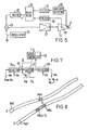
- FIG. 4 is a block diagram of a connective recording control system a VTR and which effects this operation.
- a rotary magnetic head 1 is mounted at the free end of a bimorph leaf 2 which is a lamination of two pieces of piezo-ceramic plate.
- the bimorph leaf 2 is supported at the other end on a rotary head drum (not shown).
- a control signal is supplied to the bimorph leaf 2 so that the scanning position of the head 1 is shifted in the traverse direction of the magnetic tape.
- the output (reproduced radio frequency signal) PB-RF of the head 1 is supplied to a tracking servo circuit 3, which produces a tracking error signal e for correcting the relative deviation between the head 1 and the track.
- the tracking error signal e is supplied through the playback (PB) side of a selection switch 4 to the bimorph leaf 2, which adjusts the height of the head 1 so as to correct the tracking error.
- the tracking servo circuit 3 may be of generally known form as illustrated for example in Figure 5.
- An oscillator 25 generates a wobbling signal w of a frequency in the range several hundred Hz to several kHz, which is supplied through an adder 26 and an amplifier 27 to the bimorph leaf 2.
- the head 1 is wobbled with an amplitude of 10 to 20% of the track width while it is scanning the track.
- the envelope of the output PB-RF from the head 1 is therefore amplitude modulated (AM) at the wobbling frequency.
- AM amplitude modulated
- the degree of modulation varies depending on the head position relative to the track. For example, if the head 1 deviates from the track centre in a first direction, the output PB-RF will decrease when the head 1 swings in the first direction, and the output PB-RF will increase when the head 1 swings in the opposite direction. If the head 1 deviates in the opposite direction, the output PB-RF will vary oppositely.
- a tracking error signal can be obtained.
- the output of a strain gauge 28 attached on the bimorph leaf 2 can be used.
- the output PB-RF from the head 1 is supplied to an envelope detector circuit 29, where the AM component of the output PB-RF is detected.
- the output of the strain gauge 28 and the output of the detector circuit 29 are supplied through band-limiting filters 30 and 31, respectively, to a multiplier 32, where the correlation between the signals is taken.
- the multiplier 32 derives the tracking error signal e with its magnitude representing the deviation of the head 1 from the track and with its polarity representing the direction of the deviation.
- the tracking error signal e is supplied through a filter 33 to the adder 26 and added to the wobbling signal w, then the resultant signal is supplied through the amplifier 27 to the bimorph leaf 2 as a tracking correction signal. As a result, tracking error can be corrected.
- a tracking servo circuit 3 different from that shown in Figure 5, an arrangement is known in which the difference of output levels of a plurality of heads or the difference of reproduced signal levels of a plurality of tracks is detected to obtain the tracking error signal.
- the head output amplitude A at the maximum peak position of the wobbling signal w and the head output amplitude B at the minimum peak position are detected to obtain the tracking error signal e as a function of (A-B)/(A+B).
- pilot signals of individual frequencies are recorded on each track or in each horizontal segment of one track, and the reproduced level of a pilot signal on one reproduced track and the cross-level of another pilot signed on an adjacent track are compared with each other to obtain the tracking error signal e. Any of these arrangements may be used as the tracking servo circuit shown in Figure 4.
- the tracking servo circuit 3 provides the tracking error signal e (tracking correction signal) as described above.
- the tracking error signal e is supplied to a sample/hold circuit 5, and the tracking error signal e is sampled and held sequentially at a plurality of sampling points on one track.
- Figure 6 shows sampling points (or blocks) on the track on the tape.
- 32 sampling points are assigned to one track so as to sample the tracking correction signal.
- the sampling pulses are produced, by a timing circuit 6 in synchronization with the reproduced vertical sync signal, for example.
- 8-bit memories M1 to M32 are provided corresponding to the sampling points 1 to 32 shown in Figure 6.
- An arbitrary output of the memories M1 to M32 is selected by a selector 9 and supplied to a digital-to-analog (D/A) converter 10 so that it is converted into an analog signal.
- the comparator 8 determines the superiority between the sampled data dx and mx, and produces the detection signal c with a high level or a low level depending on the result.
- the detection signal c is then supplied to a data correction circuit 11.
- the corrected data mx' is then returned through the selector 12 to the same memory Mx or the next memory Mx+1.
- the data correction circuit 11 has an adder/ subtractor 36 and a buffer (or register) 37 as shown in Figure 7.
- Data mx read out from the memory Mx is transmitted through a selector 12a and a gate 38, and written temporarily into the buffer 37.
- the output of the buffer 37 undergoes an arithmetic operation while it is supplied through the adder/subtractor 36 and the gate 38 and returned to the input of the buffer 37, so that correction of ⁇ n is carried out for the contents mx of the buffer 37.
- Addition and subtraction are switched in response to the output detection signal c of the comparator 8, and the following correcting process is performed:
- Control pulses Sa and Sb for the selectors 12a and 12b, a selection control pulse Sg for the gate 38, and read and write control pulses SR and SW for the buffer 37 are supplied from the timing circuit 6 in Figure 4. These control pulses are generated in each sampling period, so that the correcting operation for the contents of the memory Mx is performed in response to each sample data dx.
- a non-volatile memory 17 which stores reference data for the tracking correction signal are read out by the control signal from the timing circuit 6, and converted into an analog reference tracking correction signal g by a digital-to-analog (D/A) converter 18.
- the tracking correction signal g is supplied through the REC contact of the selection switch 15 to the low-pass filter 16, and further supplied through the REC contact of the selection switch 4 to the bimorph leaf 2.
- the scanning trace of the head 1 is controlled so that tracks of the standard pattern are formed.
- the contents of the non-volatile memory 17 are read out sequentially in response to the control signal from the timing circuit 6 and supplied to the comparator 8 through the ED contact of the selection switch 7. Then, the contents of the memories M1 to M32 are corrected by the data correction circuit 11 so that they gradually approach the contents of the non-volatile memory 17. After the correcting operation has converged, to equalize the contents of the memories M1 to M32 to the contents of the reference non-volatile memory 17, the contents of the memories M1 to M32 are read out repetitively and converted into analog signals, then supplied to the bimorph leaf 2.
- the tracking correction signal e supplied from the tracking servo circuit 3 to the bimorph leaf 2 during reproduction is sampled at a plurality of sampling points by the sample/hold circuit 5.
- Sample data dx at each sampling point is compared with respective data mx stored in one of the memories M1 to M32, and the memory contents are increased by one quantized step (1 bit) when the sample data dx is larger than the stored data or the memory contents are reduced by one quantized step (1 bit) when the sample data is smaller than the stored data.
- the result of the operation is written in the memory Mx with the address corresponding to the sampling point.
- Figure 8 is a diagram of two tracks on the tape, for explaining the horizontal and vertical smoothing processes.
- the horizontal smoothing (in the longitudinal direction of the track) is carried out by a process in which sample data dBx at a sampling point x on the track B are compared with data mB(x-1) at the previous sampling point on the same track stored in the memory M(x-1) as shown in Figure 8 to obtain a new data mBx as the result of correction based on the data mB(x-1), and it is written in the memory Mx.
- sample data dBx is compared with data mBx in the memory Mx so that data mB(x+1) to be written to the next memory Mx+1 is obtained.
- sample data of the tracking correction signal e which is averaged with respect to the longitudinal direction of the track are accumulated in the memories Ml to M32.
- the difference of sample data dx on each track (in the longitudinal direction of the tape) cannot be a factor for determining data accumulated in the memories M1 to M32. That is, data on each track are independent on each other, and the inter-track variation of data (sample data of each track) is left unrestrained.
- smoothed sample data on one track has a restricted quantized gradient, because only one quantized step per one sampling interval is allowed, and thus the continuity of data in the longitudinal direction of the track is ensured to some extent.
- smoothed sampled data accumulated in the memories M1 to M32 by the horizontal smoothing operation can be used as correction data to be supplied to the bimorph leaf 2 in the standard recording mode.
- the above sample data is suitable for use in the correction control signal for modifying the deformation of the track shape which occurs during recording.
- data mB1 at the beginning of a track has no memory corresponding to the previous sampling point, and thus data mA1 on the previous track A is used as the base data for obtaining the data mB1. This corresponds to vertical smoothing.
- horizontally smoothed sample data is suitable as correction data to modify the deformation of the track which occurs during standard recording.
- This correction data for standard (or normalized) recording can be obtained by reproducing a reference tape in a controlled environment.
- the reference tape has basically the same mechanical and electrical characteristics as those of an ordinary tape, but is made of a magnetic tape material having a mechanical shape in the centre value of the distribution for ordinary tapes and manufactured by particularly controlling the accuracy and distribution of the mechanical shape, such as the tape width, linearity, the one side expansion, and the shape of the edge surface and major surface.
- the reference tape is obtained using a reference VTR having a high aging stability and very high mechanical accuracy.
- the temperature, humidity and cleanness of the surface are also controlled, and the pattern accuracy is checked by an optical method.
- the reference tape can be deformed to some extent in a different environment, and can also be deformed when it wrapped on the tape guide system of a different VTR. In order to prevent the possibility of irreversible deformation of track patterns, the number of reproducing operations for the reference tape is limited.
- sample data processed using the foregoing horizontal smoothing under this condition can be used as correction data for modifying the track deformation in standard recording.
- sample data accumulated in the memories M1 to M32 in Figure 4 is supplied to the non-volatile memory 17 through the selector 12.
- the contents of the memory 17 are read out sequentially and converted into an analog correction voltage by the D/A converter 18, then supplied through the REC contact of the selection switch 15, the low-pass filter 16 and the REC contact of the selection switch 4 to the bimorph leaf 2 as a position control voltage for the movable head 1.
- a track deformation which occurs during recording is modified in advance, and at least the deviation of track deformation from the centre value (inherent value) can be corrected in an ordinary environment.
- the inherent value of track deformation can be extracted separately from random deformation due to disturbance noise and the like, and it is at least possible to prevent the involvement of random deformation components other than the inherent value into recording patterns.
- the nature of sample data which is represented by the tracking correction signal differs from correction data for normalized recording written in the non-volatile memory 17. What is required in this case is the continuity of the old and new track patterns in the neighbourhood of the editing point, rather than the modification of the inherent value of the machine itself. Therefore, it is important to obtain sample data by smoothing the tracking correction signal for a few tracks immediately before the editing point. This is possible by vertical smoothing. If there is some correlation between tracks, the variation (gradient) of sample data is not restricted in the longitudinal direction (horizontal direction) of the track as described previously, and sampling is possible on any track deformation curved or any irregular deformation. For example, a partial track deformation before the editing point due to a deflection of tape running in recording can be memorized properly as the tracking correction signal.
- Figure 9 is a three-dimensional diagram with its z-axis representing the magnitude of sample data stored in the memories M1 to 32, showing its variation in the longitudinal direction of the track (x-direction) and the longitudinal direction of the tape (y-direction).
- portion U is a previous recording portion and black marks indicate smoothed sample data at each sampling point.
- the variation of data in the longitudinal direction of the tape (y-direction or vertical direction) is limited to a certain gradient, whereas the variation in the longitudinal direction of the track (x-axis or horizontal direction) is not restricted, thus deformation on each track is sampled accurately.
- Data sampled immediately before the editing point ED includes individual or common deformation patterns of each track from which random noises on each track (vertical direction) have been removed by smoothing.
- the VTR is changed over to the edit-recording mode.
- sample data of the tracking correction signal obtained by vertical smoothing and stored in the memories M1 to M32 in Figure 4 is held. This data is read out from the memories M1 to M32 sequentially, and converted into the analog voltage by the D/A converter 10, then supplied through the ED contact of the selection switch 15, the low-pass filter 16 and the ED contact of the selection switch 4 to the bimorph leaf 2 as the control signal.
- continuity of track patterns before and after the editing point is maintained as shown in Figure 3.
- data in the memories M1 to M32 will vary sequentially by the succeeding process as shown in a new recording region V in Figure 9. That is, data for correcting the mechanical characteristic of the VTR stored in the non-volatile memory 17 in Figure 4 is read out sequentially in synchronization with the reading of the main memories M1 to M32, and converted into the analog signal by the D/A converter 18, and then supplied through the ED contact of the selection switch 7 to the comparator 8.
- the D/A converted value from the output of the memories M1 to M32 is supplied to the bimorph leaf 2 and also to another input of the comparator 8, and the comparator 8 compares both signals at each sampling point and supplies a correction signal c to the data correcting circuit 11 if there is a difference.
- the data correcting circuit 11 performs adding or subtracting correction by a certain value n (for example, one quantized step) for the contents of the memories M1 to M32 in response to the correction signal as in the case of the reproduction mode. Consequently, the contents of the memories M1 to M32 approach the data stored in the non-volatile memory 17 with a gradient limited in the vertical direction to a certain value as shown by marks 'x' in Figure 9. The time taken to reach the final value differs in each case. Finally, however, the data coincides with the contents of the non-volatile memory 17 and is fixed there as shown by circles in Figure 9.
- the tracking correction signal (relative tracking error) is considered to include a component of the inherent value of the track deformation itself, a random component during reproduction, and a component of track deformation corresponding to some specific reason such as the nature of the reproducing apparatus.
- these three components need to be included in the data so as to maintain the continuity of track patterns, however, after the editing point, it is not correct to retain all of the components. Since tape editing is generally performed a multiple number of times, the random component could be accumulated. It is also possible that track deformation having some specific trend would accumulate and grow, and this must be prevented.
- the highest possible track deformation having a specific trend is an offset error of the tracking servo system (a system including the tracking servo circuit 3 and the bimorph leaf 2) in Figure 4, or an offset of the recording position on the track in the drum servo system, capstan servo system or tension servo system in different operational modes that occurs when the reproduction mode is changed over to the recording mode at the editing point.
- track deformation can occur due to the difference of recording and reproducing regions on the magnetic head on its confronting surface of the tape when the magnetic head is in unbalanced contact with the tape.
- the recording track pattern can grow into an abnormal shape due to the cumulative effect of joining several tens of times to several hundreds of times.
- the random component even it if it is accumulated, has less possibility of causing the growth of deformation, whereas the offset component of one specific polarity or direction is accumulated directly.
- accumulation of the offset value can even lead to the formation of patterns of a different shape.
- the continuity of patterns and the elimination of offset deformation at the editing point are accomplished at the same time by leading the data in the memories M1 to M32 to the standard correction data stored in the non-volatile memory 17 after the editing point. From the view point of probability, it is possible that more accurate connective recording track patterns can be formed with sample data in the memories M1 to M32 left unchanged. However, in considering the worst condition as mentioned above and the usefulness of correction or modification of recording tracks so that the operating range of the tracking servo system is not exceeded during reproduction it can be said that approximation to data in the non-volatile memory 17 is more correct.
- the track interval can be changed, resulting in difficult tracking in reproduction.
- the variation of the track pitch is small and the correlation of the shapes between tracks is not disturbed much, thus no problem will occur even if the response of the tracking servo system is not high during reproduction.
- the control circuit of Figure 4 performs smoothing for the tracking correction signal e in the horizontal or vertical direction during reproduction to produce sample data, and stores the data in the memories M1 to M32.
- This sample data can be used as an auxiliary tracking correction signal when an abnormal drop-out has occurred in the reproduced output from the head 1. That is, by switching the selection switch 4 to the DO side in response to the output from the drop-out detecting circuit 14 in Figure 4, tracking can be continued without any problem even if the tracking servo circuit 3 fails to operate at the occurrence of a drop-out. When the drop-out has ceased, the tracking servo system responds quickly and the normal operation is regained in a very short time.
- smoothed or averaged sample data derived from the tracking correction signal has a significant meaning. For example, if an immediate data without smoothing and stored at the previous track was to be used as the auxiliary tracking correction signal against a drop-out as mentioned above, the reproduction system would be greatly disturbed to use data of critical tracking immediately before the drop-out has occurred. If this data is wrong, the system would be disturbed much more, possibly resulting in a failure of recovery. By use of smoothed data, there is no possibility at all of falling into such an unrecoverable 'hole' in the operation.
- each component block is controlled by the output from the timing circuit 6, the function of which is switched by the operation mode signal OP-M including REC (recording), PB (reproduction) and ED (editing).
- the synchronizing reference for the timing circuit 6 is the reproduction sync signal PB-VD during reproduction or the external reference sync signal Ref. Sync during recording.
- the head jump signal j is supplied, by which the synchronizing reference for the timing circuit 6 is varied so that the sampling point on the track does not lose the correspondence with the memory address.
- the tracking signal is supplied to the head position control means in order to correct the deviation of the head relative to the track on the tape, the tracking signal is sampled at a plurality of sampling points in the longitudinal direction of the track, the contents of memories corresponding to the sampling points are compared with the current sample value so as to modify the contents of the memories in a certain variation factor depending on the result of comparison thereby providing an averaged sample value of the tracking signal, and the head position control means is controlled in accordance with the sample value after the tape editing point (connection). Accordingly, the continuity of track deformation at the editing point is achieved and tracks do not intersect with each other in high speed recording, whereby stable pictures can be reproduced without any disturbance at the editing point.
- the sample value of the averaged tracking signal is used to determine the track deformation following the editing point, allowing the elimination of the effect of the singular value or abnormal value other than the inherent value of track deformation before the editing point, and thus the editing joint can be made stable.
Claims (5)
Priority Applications (1)
| Application Number | Priority Date | Filing Date | Title |
|---|---|---|---|
| AT81305075T ATE13954T1 (de) | 1980-11-12 | 1981-10-27 | Aufzeichnungs- und wiedergabeeinrichtung fuer video-signale. |
Applications Claiming Priority (2)
| Application Number | Priority Date | Filing Date | Title |
|---|---|---|---|
| JP55159111A JPS5783978A (en) | 1980-11-12 | 1980-11-12 | Video signal recorder and reproducer |
| JP159111/80 | 1980-11-12 |
Publications (2)
| Publication Number | Publication Date |
|---|---|
| EP0051428A1 EP0051428A1 (de) | 1982-05-12 |
| EP0051428B1 true EP0051428B1 (de) | 1985-06-19 |
Family
ID=15686477
Family Applications (1)
| Application Number | Title | Priority Date | Filing Date |
|---|---|---|---|
| EP81305075A Expired EP0051428B1 (de) | 1980-11-12 | 1981-10-27 | Aufzeichnungs- und Wiedergabeeinrichtung für Video-Signale |
Country Status (6)
| Country | Link |
|---|---|
| US (2) | US4443823A (de) |
| EP (1) | EP0051428B1 (de) |
| JP (1) | JPS5783978A (de) |
| AT (1) | ATE13954T1 (de) |
| CA (1) | CA1187603A (de) |
| DE (1) | DE3171055D1 (de) |
Families Citing this family (42)
| Publication number | Priority date | Publication date | Assignee | Title |
|---|---|---|---|---|
| US4485414A (en) * | 1980-07-07 | 1984-11-27 | Ampex Corporation | Servo system for positioning a movable transducing head assembly |
| JPS58147282A (ja) * | 1982-02-26 | 1983-09-02 | Nec Corp | 特殊再生装置 |
| US4550351A (en) * | 1982-03-31 | 1985-10-29 | Rca Corporation | Adaptive automatic scan tracking system |
| US4689706A (en) * | 1982-09-15 | 1987-08-25 | Ampex Corporation | Apparatus and method for adjusting the respective positions of a magnetic head and video information along a magnetic track |
| WO1984001235A1 (en) * | 1982-09-17 | 1984-03-29 | Ampex | An improved automatic head position tracking servo for a rotary head magnetic tape recording and reproducing apparatus |
| US4595960A (en) * | 1982-11-03 | 1986-06-17 | Rca Corporation | Phase-reversed dithered automatic scan tracking system |
| US4604656A (en) * | 1983-03-11 | 1986-08-05 | Mitsubishi Denki Kabushiki Kaisha | Tape stop position detecting apparatus and magnetic video reproducing apparatus using the same |
| JPS59185019A (ja) * | 1983-04-04 | 1984-10-20 | Nec Corp | 特殊再生装置 |
| JPS6083478A (ja) * | 1983-10-14 | 1985-05-11 | Fuji Photo Film Co Ltd | 回転磁気記録体トラツキング装置 |
| JPS61133010A (ja) * | 1984-11-30 | 1986-06-20 | Sony Corp | 自動トラツキング装置 |
| JPS61182622A (ja) * | 1985-02-08 | 1986-08-15 | Matsushita Electric Ind Co Ltd | 自動トラツキング装置 |
| JPH07111768B2 (ja) * | 1985-04-11 | 1995-11-29 | ソニー株式会社 | 電子編集の可能な磁気記録再生装置 |
| US4760471A (en) * | 1986-04-11 | 1988-07-26 | Ampex Corporation | System and method to improve picture quality during shuttling of video tapes |
| US4843496A (en) * | 1986-10-29 | 1989-06-27 | Eastman Kodak Company | Track-finding servomechanism utilizing the sampled output of an envelope comparison |
| JPS6450265A (en) * | 1987-08-21 | 1989-02-27 | Hashimoto Corp | System for operating vtr |
| KR970008642B1 (ko) * | 1988-01-30 | 1997-05-27 | 소니 가부시끼가이샤 | 자기 기록 및 플레이백 장치 |
| JPH06105497B2 (ja) * | 1988-06-28 | 1994-12-21 | 松下電器産業株式会社 | 記録再生装置の電子編集装置 |
| JP2587475B2 (ja) * | 1988-10-21 | 1997-03-05 | 株式会社日立製作所 | デジタル磁気記録再生装置 |
| US4935827A (en) * | 1988-11-09 | 1990-06-19 | Ampex Corporation | Dynamic head position tracking control for a magnetic tape playback system |
| JP2580341B2 (ja) * | 1989-09-29 | 1997-02-12 | 三菱電機株式会社 | 磁気記録再生装置 |
| DE4110758A1 (de) * | 1990-04-03 | 1991-11-07 | Mitsubishi Electric Corp | Verfahren fuer eine magnetische aufnahme und wiedergabe |
| US5050018A (en) * | 1990-04-19 | 1991-09-17 | Exabyte Corporation | Apparatus and method for reading helically recorded tracks and rereading tracks as necessary |
| JP3021606B2 (ja) * | 1990-10-31 | 2000-03-15 | ソニー株式会社 | キャプスタンサーボ装置 |
| US5191491A (en) * | 1990-11-09 | 1993-03-02 | Exabyte Corporation | Method and apparatus for reading distorted helical stripes |
| KR920020488A (ko) * | 1991-04-12 | 1992-11-21 | 더글라스 엠 길버어트 | 신호 레코더에서의 삽입 편집을 자동으로 적절하게 실행하는 1채널 방법 및 장치 |
| KR920020475A (ko) * | 1991-04-12 | 1992-11-21 | 더글라스 엠 길버어트 | 신호 레코더에서의 삽입 편집을 자동으로 적절하게 실행하는 2채널 방법 및 장치 |
| JP3161479B2 (ja) * | 1992-02-13 | 2001-04-25 | ソニー株式会社 | 情報信号の記録装置 |
| JP2792792B2 (ja) * | 1992-08-24 | 1998-09-03 | 三菱電機株式会社 | 自動トラッキング装置 |
| US5696755A (en) * | 1992-11-04 | 1997-12-09 | Storage Technology Corporation | System for minimizing the effects of scratches on recording media |
| US5349481A (en) * | 1993-06-10 | 1994-09-20 | Exabyte Corporation | Apparatus and method for distorted track data recovery by rewinding and re-reading the tape at a slower than nominal speed |
| US6181506B1 (en) * | 1994-07-26 | 2001-01-30 | Canon Kabushiki Kaisha | Tracking control device |
| US6367047B1 (en) | 1998-10-20 | 2002-04-02 | Ecrix | Multi-level error detection and correction technique for data storage recording device |
| US6307701B1 (en) | 1998-10-20 | 2001-10-23 | Ecrix Corporation | Variable speed recording method and apparatus for a magnetic tape drive |
| US6246551B1 (en) | 1998-10-20 | 2001-06-12 | Ecrix Corporation | Overscan helical scan head for non-tracking tape subsystems reading at up to 1X speed and methods for simulation of same |
| US6381706B1 (en) | 1998-10-20 | 2002-04-30 | Ecrix Corporation | Fine granularity rewrite method and apparatus for data storage device |
| US6308298B1 (en) | 1998-11-16 | 2001-10-23 | Ecrix Corporation | Method of reacquiring clock synchronization on a non-tracking helical scan tape device |
| US6603618B1 (en) | 1998-11-16 | 2003-08-05 | Exabyte Corporation | Method and system for monitoring and adjusting tape position using control data packets |
| US6421805B1 (en) | 1998-11-16 | 2002-07-16 | Exabyte Corporation | Rogue packet detection and correction method for data storage device |
| US6367048B1 (en) | 1998-11-16 | 2002-04-02 | Mcauliffe Richard | Method and apparatus for logically rejecting previously recorded track residue from magnetic media |
| US6364234B1 (en) | 2000-03-10 | 2002-04-02 | Michael Donald Langiano | Tape loop/slack prevention method and apparatus for tape drive |
| US6624960B1 (en) | 2000-03-10 | 2003-09-23 | Exabyte Corporation | Current sensing drum/cleaning wheel positioning method and apparatus for magnetic storage system |
| US20090178752A1 (en) * | 2008-01-11 | 2009-07-16 | Kyle William Behringer | Protective film applicator tool, kit, and methods of shielding a surface |
Family Cites Families (7)
| Publication number | Priority date | Publication date | Assignee | Title |
|---|---|---|---|---|
| GB1549440A (en) * | 1976-07-06 | 1979-08-08 | Data Recording Instr Co | Magnetic storage devices |
| JPS6030008B2 (ja) * | 1976-08-20 | 1985-07-13 | ソニー株式会社 | 再生装置 |
| JPS5539478A (en) * | 1978-09-14 | 1980-03-19 | Sony Corp | Regenerator of video signal |
| NL7812286A (nl) * | 1978-12-19 | 1980-06-23 | Philips Nv | Werkwijze voor het lezen en/of schrijven van informatie en een inrichting voor het uitvoeren van de werkwijze. |
| JPS5597025A (en) * | 1979-01-17 | 1980-07-23 | Toshiba Corp | Positioning device using microcomputer |
| JPS56101621A (en) * | 1980-01-17 | 1981-08-14 | Victor Co Of Japan Ltd | Tracking system of magnetic reproducing device |
| JPS5780880A (en) * | 1980-11-07 | 1982-05-20 | Sony Corp | Video signal reproducing device |
-
1980
- 1980-11-12 JP JP55159111A patent/JPS5783978A/ja active Granted
-
1981
- 1981-10-27 DE DE8181305075T patent/DE3171055D1/de not_active Expired
- 1981-10-27 EP EP81305075A patent/EP0051428B1/de not_active Expired
- 1981-10-27 AT AT81305075T patent/ATE13954T1/de not_active IP Right Cessation
- 1981-11-03 US US06/317,867 patent/US4443823A/en not_active Expired - Lifetime
- 1981-11-03 CA CA000389281A patent/CA1187603A/en not_active Expired
-
1984
- 1984-01-30 US US06/575,266 patent/US4486796A/en not_active Expired - Lifetime
Also Published As
| Publication number | Publication date |
|---|---|
| JPS5783978A (en) | 1982-05-26 |
| JPS6348472B2 (de) | 1988-09-29 |
| ATE13954T1 (de) | 1985-07-15 |
| US4486796A (en) | 1984-12-04 |
| EP0051428A1 (de) | 1982-05-12 |
| DE3171055D1 (en) | 1985-07-25 |
| US4443823A (en) | 1984-04-17 |
| CA1187603A (en) | 1985-05-21 |
Similar Documents
| Publication | Publication Date | Title |
|---|---|---|
| EP0051428B1 (de) | Aufzeichnungs- und Wiedergabeeinrichtung für Video-Signale | |
| USRE40545E1 (en) | Servo control appartaus and method using absolute value input signals | |
| US6594103B1 (en) | Read channel generating absolute value servo signal | |
| US4404601A (en) | Head tracking control system | |
| US4268876A (en) | Magnetic reproducing device | |
| US5072319A (en) | Magnetic recording/or reproducing apparatus | |
| US5907527A (en) | Optical disc reproducing method and apparatus for controlling servo gain and/or offset | |
| US6130797A (en) | Magnetic recorder and magnetooptical recorder | |
| CA1160337A (en) | Tracking control system | |
| US4901166A (en) | Tracking control for VTR editing employing previously recorded tracking information | |
| US4760471A (en) | System and method to improve picture quality during shuttling of video tapes | |
| US5488520A (en) | Data recording and playback apparatus using helical scan system with magnetic head for recording and playing back pattern signal for tracking in tracking area within helical track | |
| EP0081356A1 (de) | Gerät zur Wiedergabe von Videosignalen | |
| GB2097216A (en) | Tracking control system | |
| US5589997A (en) | Tracking control method and apparatus for video recorder which adds a combined first and second tracking error signal to the next tracking error signal | |
| US5500775A (en) | Data recording and reproducing apparatus | |
| EP0565367B1 (de) | Ein zur Datenrückgewinnung Standbildtechniken benutzendes Datenaufnahmeverfahren | |
| JP3288131B2 (ja) | データ記録再生装置 | |
| JP2550202B2 (ja) | 回転ヘッド型再生装置 | |
| KR0176481B1 (ko) | 비디오카세트레코더의 트랙킹장치 | |
| JPS6321968B2 (de) | ||
| JP2966160B2 (ja) | 磁気記録再生装置 | |
| JPS6321966B2 (de) | ||
| JPH04205811A (ja) | 磁気記録再生装置 | |
| JPH05166259A (ja) | 磁気記録再生装置 |
Legal Events
| Date | Code | Title | Description |
|---|---|---|---|
| PUAI | Public reference made under article 153(3) epc to a published international application that has entered the european phase |
Free format text: ORIGINAL CODE: 0009012 |
|
| 17P | Request for examination filed |
Effective date: 19811029 |
|
| AK | Designated contracting states |
Designated state(s): AT DE FR GB NL |
|
| GRAA | (expected) grant |
Free format text: ORIGINAL CODE: 0009210 |
|
| AK | Designated contracting states |
Designated state(s): AT DE FR GB NL |
|
| REF | Corresponds to: |
Ref document number: 13954 Country of ref document: AT Date of ref document: 19850715 Kind code of ref document: T |
|
| REF | Corresponds to: |
Ref document number: 3171055 Country of ref document: DE Date of ref document: 19850725 |
|
| ET | Fr: translation filed | ||
| PLBE | No opposition filed within time limit |
Free format text: ORIGINAL CODE: 0009261 |
|
| STAA | Information on the status of an ep patent application or granted ep patent |
Free format text: STATUS: NO OPPOSITION FILED WITHIN TIME LIMIT |
|
| 26N | No opposition filed | ||
| PGFP | Annual fee paid to national office [announced via postgrant information from national office to epo] |
Ref country code: FR Payment date: 20001010 Year of fee payment: 20 |
|
| PGFP | Annual fee paid to national office [announced via postgrant information from national office to epo] |
Ref country code: AT Payment date: 20001011 Year of fee payment: 20 |
|
| PGFP | Annual fee paid to national office [announced via postgrant information from national office to epo] |
Ref country code: DE Payment date: 20001023 Year of fee payment: 20 |
|
| PGFP | Annual fee paid to national office [announced via postgrant information from national office to epo] |
Ref country code: GB Payment date: 20001025 Year of fee payment: 20 |
|
| PGFP | Annual fee paid to national office [announced via postgrant information from national office to epo] |
Ref country code: NL Payment date: 20001026 Year of fee payment: 20 |
|
| PG25 | Lapsed in a contracting state [announced via postgrant information from national office to epo] |
Ref country code: GB Free format text: LAPSE BECAUSE OF EXPIRATION OF PROTECTION Effective date: 20011026 |
|
| PG25 | Lapsed in a contracting state [announced via postgrant information from national office to epo] |
Ref country code: AT Free format text: LAPSE BECAUSE OF EXPIRATION OF PROTECTION Effective date: 20011027 Ref country code: NL Free format text: LAPSE BECAUSE OF EXPIRATION OF PROTECTION Effective date: 20011027 |
|
| REG | Reference to a national code |
Ref country code: GB Ref legal event code: PE20 Effective date: 20011026 |
|
| NLV7 | Nl: ceased due to reaching the maximum lifetime of a patent |
Effective date: 20011027 |