US5050018A - Apparatus and method for reading helically recorded tracks and rereading tracks as necessary - Google Patents
Apparatus and method for reading helically recorded tracks and rereading tracks as necessary Download PDFInfo
- Publication number
- US5050018A US5050018A US07/511,312 US51131290A US5050018A US 5050018 A US5050018 A US 5050018A US 51131290 A US51131290 A US 51131290A US 5050018 A US5050018 A US 5050018A
- Authority
- US
- United States
- Prior art keywords
- read
- azimuthal paths
- offset
- blocks
- block
- Prior art date
- Legal status (The legal status is an assumption and is not a legal conclusion. Google has not performed a legal analysis and makes no representation as to the accuracy of the status listed.)
- Expired - Fee Related
Links
Images


Classifications
-
- G—PHYSICS
- G11—INFORMATION STORAGE
- G11B—INFORMATION STORAGE BASED ON RELATIVE MOVEMENT BETWEEN RECORD CARRIER AND TRANSDUCER
- G11B15/00—Driving, starting or stopping record carriers of filamentary or web form; Driving both such record carriers and heads; Guiding such record carriers or containers therefor; Control thereof; Control of operating function
- G11B15/18—Driving; Starting; Stopping; Arrangements for control or regulation thereof
- G11B15/46—Controlling, regulating, or indicating speed
- G11B15/467—Controlling, regulating, or indicating speed in arrangements for recording or reproducing wherein both record carriers and heads are driven
- G11B15/4673—Controlling, regulating, or indicating speed in arrangements for recording or reproducing wherein both record carriers and heads are driven by controlling the speed of the tape while the head is rotating
- G11B15/4675—Controlling, regulating, or indicating speed in arrangements for recording or reproducing wherein both record carriers and heads are driven by controlling the speed of the tape while the head is rotating with provision for information tracking
-
- G—PHYSICS
- G11—INFORMATION STORAGE
- G11B—INFORMATION STORAGE BASED ON RELATIVE MOVEMENT BETWEEN RECORD CARRIER AND TRANSDUCER
- G11B15/00—Driving, starting or stopping record carriers of filamentary or web form; Driving both such record carriers and heads; Guiding such record carriers or containers therefor; Control thereof; Control of operating function
- G11B15/18—Driving; Starting; Stopping; Arrangements for control or regulation thereof
- G11B15/1808—Driving of both record carrier and head
- G11B15/1825—Driving of both record carrier and head driving or moving the head in a direction which cuts across the direction of travel of the tape, e.g. for helicoïdal scanning
- G11B15/1833—Driving of both record carrier and head driving or moving the head in a direction which cuts across the direction of travel of the tape, e.g. for helicoïdal scanning with head driven in a plane, cyclically around an axis, e.g. on headwheel
- G11B15/1841—Driving of both record carrier and head driving or moving the head in a direction which cuts across the direction of travel of the tape, e.g. for helicoïdal scanning with head driven in a plane, cyclically around an axis, e.g. on headwheel with provision for information tracking by moving the transducing part of the head relative to the headwheel, in the direction of the scanning movement, e.g. for skew or time base correction
- G11B15/185—Driving of both record carrier and head driving or moving the head in a direction which cuts across the direction of travel of the tape, e.g. for helicoïdal scanning with head driven in a plane, cyclically around an axis, e.g. on headwheel with provision for information tracking by moving the transducing part of the head relative to the headwheel, in the direction of the scanning movement, e.g. for skew or time base correction using signals recorded in tracks disposed in parallel with the scanning direction
-
- G—PHYSICS
- G11—INFORMATION STORAGE
- G11B—INFORMATION STORAGE BASED ON RELATIVE MOVEMENT BETWEEN RECORD CARRIER AND TRANSDUCER
- G11B5/00—Recording by magnetisation or demagnetisation of a record carrier; Reproducing by magnetic means; Record carriers therefor
- G11B5/48—Disposition or mounting of heads or head supports relative to record carriers ; arrangements of heads, e.g. for scanning the record carrier to increase the relative speed
- G11B5/58—Disposition or mounting of heads or head supports relative to record carriers ; arrangements of heads, e.g. for scanning the record carrier to increase the relative speed with provision for moving the head for the purpose of maintaining alignment of the head relative to the record carrier during transducing operation, e.g. to compensate for surface irregularities of the latter or for track following
- G11B5/584—Disposition or mounting of heads or head supports relative to record carriers ; arrangements of heads, e.g. for scanning the record carrier to increase the relative speed with provision for moving the head for the purpose of maintaining alignment of the head relative to the record carrier during transducing operation, e.g. to compensate for surface irregularities of the latter or for track following for track following on tapes
- G11B5/588—Disposition or mounting of heads or head supports relative to record carriers ; arrangements of heads, e.g. for scanning the record carrier to increase the relative speed with provision for moving the head for the purpose of maintaining alignment of the head relative to the record carrier during transducing operation, e.g. to compensate for surface irregularities of the latter or for track following for track following on tapes by controlling the position of the rotating heads
Definitions
- This invention pertains to apparatus and method for reading helically recorded magnetic tape, and particularly to apparatus and method for recovery from errors that occur when reading helically recorded magnetic tape having distorted tracks.
- magnetically reproducible signals are recorded on magnetic storage media in the form of parallel tracks or stripes. It is well known that operational problems may cause one or more tracks of information, helically recorded on magnetic tape storage media, to appear upon playback or reading as a distorted track.
- One type of distorted track is a curved track.
- problems such as those associated with the handling or guiding of a magnetic tape as it is being read may cause a track to appear as a curved track.
- the prior art EXB-8200 helical tape drive records informational data in a blocked format, with eight data blocks being recorded per track or stripe.
- the blocks need not necessarily be recorded nor read in any order, as explained in U.S. patent application Ser. No. 07/069,132 filed July 2, 1987, entitled METHOD APPARATUS FOR DATA BUFFER MANAGEMENT, commonly assigned herewith and incorporated herein by reference.
- the magnetic tape read by the EXB-8200 is formatted so that every data block has a header portion that includes block-identifying information.
- a micro-controller Upon reading of a block, a micro-controller stores the data contents of the block in a data buffer and the block-identifying information into an allocation table. Using the block-identifying information stored in the allocation table, the micro-controller ascertains the order for utilizing the corresponding data blocks stored in the data buffer.
- the microcontroller would request re-reading of the tape in hopes that the missing block would be detected and read upon re-read.
- the read head would follow essentially the same path as during the initial read, with the result that a block on a curved track that evaded discovery during an initial read attempt could also be evasive during subsequent read attempts.
- An advantage of the present invention is the provision of method and apparatus that facilitates the reading of distorted tracks, such as curved tracks, when tracking or servo information is not provided continuously or periodically along the tracks.
- a helical drive system reads tracks recorded on a storage medium, including tracks which appear as distorted tracks.
- Each track comprises a plurality of blocks of recorded data, with each block having unique block-identifying information provided in a block header.
- the drive system includes a read head positioned on a rotatable drum which contacts the storage medium in such a manner that the read head traverses predetermined original azimuthal paths across the storage medium for reading blocks recorded along each of the original azimuthal paths.
- the original azimuthal paths are straight paths.
- the block-identifying information is stripped from the block header.
- Non-header portions of the block known as block "user data” or the "user block” are stored in a data buffer.
- the block-identifying information for each user block loaded into the data buffer is stored in an allocation table.
- One of such block-identifying parameters is known as BLOCK ID.
- the allocation table thereby essentially serves as a directory for listing the BLOCK IDs for the user blocks stored in the data buffer.
- Blocks stored in the data buffer are made available to a user or utilization device, such as a host computer system.
- the utilization device requests additional blocks from the data buffer as needed, and expects to receive the blocks in predetermined order according to a monotonic increasing series of BLOCK ID values.
- a controller included in the helical drive system determines, by consulting the allocation table, whether a block having the next BLOCK ID is stored in the data buffer. If the sought BLOCK ID value is located in the allocation table, the corresponding block is transmitted from the data buffer to the utilization device.
- the controller executes a loop known as the OFFSET READ LOOP.
- the storage medium is re-positioned (e.g., re-wound) in preparation for a re-reading of a portion of the storage medium.
- the controller determines a modified azimuthal path to be followed by the read head.
- the modified azimuthal path is essentially parallel to the original azimuthal path travelled by the read head, but may be laterally offset or displaced from the original azimuthal path with respect to the direction of tape travel.
- the amount of the read head displacement relative to the original azimuthal path is known as the offset degree value or offset degree. The amount of the offset or displacement depends on the number of times the loop has been executed (as stored in a counter OFFSET LOOP COUNTER).
- the storage medium is re-read with the head travelling the modified azimuthal path.
- a determination is made whether the previously missing block(s) were read during the most recent execution. If any missing block(s) were read, the block-identifying information is stored in the allocation table and the user block is stored in the data buffer. If any previously missing block has yet to be located, the OFFSET READ LOOP is again executed, with the controller choosing a different offset value for the next execution of the OFFSET READ LOOP.
- the read head When all formerly missing blocks are successfully read, the read head remains positioned with the last offset degree value for further reading of the tape. If this last offset degree value ultimately results in holes in the allocation table during subsequent read operations, the read head returns to a zero offset during a first execution of the OFFSET READ LOOP.
- the offset selected by the controller is zero.
- the offset is the maximum displacement in a negative directional sense from the original azimuthal path.
- the offset is the maximum displacement in a positive directional sense from the original azimuthal path.
- the subsequent executions, or "retries”, are binary search divisions, ending finally, in the offset magnitude being restored to zero. If, after ten retries, the missing blocks still cannot be read, a permanent read error is generated.
- a controller executes a DYNAMIC OFFSET READ LOOP to select from a plurality of possible offset degree values based on the historical success rate of the offset degree values in reading missing blocks.
- a utilization sequence of the non-zero offset degree values is periodically re-ordered based on the value of success counters associated with the corresponding offset degree values.
- the success counters tabulate the number of formerly missing blocks successfully read with the associated head offset degree value.
- the offset degree values are stored in RAM memory, thereby facilitating the rearrangement of the utilization sequence. The rearrangement or reordering results in the usage of offset degree values in an order of likelihood of success of reading missing blocks.
- FIG. 1 is a schematic illustration of recording on magnetic tape by tracks using a helical scan recording arrangement.
- FIG. 2 is a schematic illustration of magnetic head placement on a rotatable drum for helical scan recording on magnetic tape according to an embodiment of the invention.
- FIG. 3 is a schematic illustration of helical tracks properly recorded on magnetic tape, and a particular format thereof.
- FIG. 4 is a schematic illustration of distorted tracks appearing on magnetic tape upon a tape read operation.
- FIG. 4A is s a schematic illustration showing original azimuthal paths across distorted tracks appearing on magnetic tape during a tape read operation.
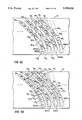
- FIG. 4B is a schematic illustration showing first modified paths across distorted tracks appearing on magnetic tape during a tape read operation.
- FIG. 4C is a schematic illustration showing second modified azimuthal paths across distorted tracks appearing on magnetic tape during a tape read operation.
- FIG. 4D is a schematic illustration showing third modified azimuthal paths across distorted tracks appearing on magnetic, tape during a tape read operation.
- FIG. 5 is a schematic illustration of circuitry included in a helical scan drive system according to an embodiment of the invention.
- FIG. 6 is a schematic illustration depicting a portion of a controller memory including an allocation table according to an embodiment of the invention.
- FIG. 7 is a schematic illustration depicting a memory organization scheme for a data buffer according to an embodiment of the invention.
- FIG. 8 is a schematic illustration of steps executed by a controller of the embodiment of FIG. 5 according to a mode of the invention.
- FIG. 9 is a schematic illustration showing original azimuthal paths and modified paths across distorted tracks appearing on magnetic tape during a tape read operation.
- FIG. 10 is a schematic illustration of steps included in a DYNAMIC OFFSET READ LOOP executed by a controller of the embodiment of FIG. 5 according to a mode of the invention.
- FIGS. 1 and 2 A helical-scan drive system 10 for recording on and reading magnetic tape 12 is illustrated in FIGS. 1 and 2.
- a drum 14 is angularly oriented with respect to the edges and direction of travel 15 of magnetic tape 12.
- drum 14 has heads 16A, 16B, and 16C mounted thereon to establish a physical relation between the heads on the drum 14 and the tape 12.
- Head 16A is a write (or recording head); head 16B is a servo head; and, head 16C is a read (or playback) head.
- data is recorded on the tape 12 at an angle with respect to the direction of travel 15 of the tape 12, and hence, as indicated in FIG. 1, is recorded as discrete tracks or stripes 18 when the drum is rotated at a high speed relative to the speed of the tape 12.
- the tape is preferably moved at a rate of 10.89 millimeters per second while the drum is rotated at 1800 rpm, the tape speed being controlled by the rotational speed of capstan 19. It is to be realized, however, that the operating speeds as set forth are by way of example and the invention is not meant to be limited thereto.
- FIG. 3 shows a plurality of discrete tracks 18 1 , 18 2 , 18 3 , and 18 4 properly recorded on tape 15. Being properly recorded, each of the tracks 18 extends in a straight line for a predetermined length (depicted by line 22) at an a angle 24 (also known as a "track angle” or “stripe angle") relative to the direction of tape travel (indicated by arrow 15).
- the centerlines of adjacent tracks are separated by a track pitch, represented by reference numeral 26 in FIG. 3.
- the tracks are separated by inter-track guard bands 28.
- the a angle 24 is on the order of 4.9 degrees; the track pitch is on the order of 31 micrometers.
- FIG. 3 also shows a format of tape 12 usable with the present invention.
- Each block is a complete and independent entity which can be read independently of any other data blocks.
- U.S. Pat. No. 4,835,628 entitled APPARATUS AND METHOD FOR FORMATTING AND RECORDING DIGITAL DATA ON MAGNETIC TAPE which is commonly assigned herewith and incorporated by reference herein.
- each data block contains certain header information, including a BLOCK ID and PHYSICAL BLOCK ID, the combination of which is unique for each block.
- user data and “user block” refer to the non-header portion of each block which is ultimately transmitted to a utilization device, such as a host computer.
- each track 18 contains near its beginning (i.e., before the data blocks) a servo area 30.
- the servo area 30 has stored therein signals readable by the servo head 16B and usable for positioning the heads 16A, 16B, and 16C on the drum 14 relative to the tape 12.
- a particular servo scheme and format usable in conjunction with an embodiment of the present invention is shown in U.S. Pat. No. 4,843,495, previously incorporated by reference herein.
- the servo data in the servo area 30 is recorded only at the beginning of a track 18 and is sampled only once per revolution of the heads 16.
- a "distorted track” or “distorted stripe” as used herein means a track that deviates from any one or more of the following nominal, predetermined parameters: track pitch; track angle; track length; and track straightness.
- a mechanical tape guiding problem which may cause the tape to establish an alignment which is different from the proper alignment of FIG. 3. This other or different alignment may achieve an equilibrium and persist until some change in the tape motion or external forces act on the tape to restore the tape to its desired alignment.
- the helical drive system 10 of the invention further includes a controller 50, such as a micro-processor based micro-controller, for example.
- the controller 50 is connected to a bank of RAM memory 52 in conventional fashion. As will be seen hereinafter, an allocation table is stored in the RAM memory 52.
- the controller 50 is also connected to a memory chip 54, hereinafter also known as "OFFSET MEMORY".
- the memory chip 54 is a ROM chip
- the memory chip 54 is a RAM chip.
- the memory chip 54 is programmable with offset degree values.
- the read head 16C is connected to apply signals read from the tape 12 to read circuits & clock 64 (See FIG. 5). Data to be read is received at the read circuits 64 and, together with a clock signal, is coupled to a read demodulator and deserializer 66 and to a read deformatter 68. In the read deformatter 66, certain header and referencing signals are removed from the data stream so that the recovered user data can be applied in block form to a data buffer 70. The operations of the data buffer 70 and the read deformatter 68 are managed by a read interface 72, which in turn is governed by the controller 50. Details of the structure and operation of the circuitry of FIG. 5 are understood from U.S. Pat. No. 4,835,628, already incorporated by reference.
- FIG. 5 additionally shows a user device 78 such as a host computer and an associated interface.
- the user device 78 is connected to request user data from the controller 50 and to receive user blocks from the data buffer 70.
- FIG. 6 schematically illustrates portions of the RAM memory 52 associated with the controller 50.
- the RAM memory 52 includes an allocation table 80.
- the allocation table 80 has stored therein certain parameters for as many as 248 blocks, shown as blocks 0-247 in FIG. 6.
- each block corresponds to a row of the allocation table 80.
- the parameters stored in the allocation table 80 for each block include block header information, including the BLOCK ID and PHYSICAL BLOCK ID parameters which are unique to each block.
- FIG. 7 is a schematic view of the memory organization scheme of the data buffer 70.
- the data buffer 70 includes 248K of memory for storing 248 blocks of user data, with each user block having a length of 1K.
- the read deformatter 68 when a user block of data is recognized by the read deformatter 68, the entire user block is transmitted to the data buffer 70 where the user block is stored at an appropriate address in the data buffer memory.
- the controller 50 is connected to a tape transport drive 81 to direct the transport drive 81 to transport the tape in a forward direction (for tape reading) and in a reverse (e.g., rewind) direction.
- the transport drive actuates the capstan 19.
- the controller 50 is also connected to a servo interface 82 (see FIG. 5).
- the servo interface 82 is connected to apply a tracking control signal to a servo head positioning mechanism 84.
- the head positioning mechanism 84 serves to adjust the position of the heads 16A, 16B, and 16C relative to the drum 14.
- the servo interface 82 has access to the offset values stored in the OFFSET MEMORY chip 54 via an OFFSET BUS.
- An OFFSET SELECT line from the controller 50 tells the servo interface 82 which of the offset values to use from the OFFSET MEMORY chip 54.
- FIG. 5 also shows how servo signals detected by the servo head 16B are processed and applied for use by the servo interface 82.
- the servo head 16B has its output connected to amplifier circuitry 86.
- the amplified signal from circuitry 86 is then applied to filter circuitry 88, peak detector 90; sample and hold circuitry 92; and, analog-to-digital converter (ADC) 94.
- ADC analog-to-digital converter
- the read head 16C traverses a predetermined azimuthal path across the magnetic tape 12 in the manner shown by FIG. 1. Assuming the read head 16C is correctly aligned with tracks that are properly readable as straight tracks, upon each rotation of the drum 14 the read head 16C acquires signals from eight blocks B0, B1, . . . B7 as described hereinbefore.
- the signals from the eight blocks acquired from the read head 16C are applied to the read circuits 64, and from thence to the read demodulator & deserializer 66 and to the read deformatter 68.
- the read deformatter 68 analyzes the signals obtained from the read head 16C and, by examining block header parameters exacted from the signals, determines the number of blocks that were in fact read from the track.
- the read deformatter 66 essentially strips the block header from each block, and for each block makes available to the read interface 72 certain block header parameters (including BLOCK ID and PHYSICAL BLOCK ID).
- the controller 50 stores these block header parameters in the allocation table 80 of RAM 52 in the format shown in FIG. 6.
- the allocation table 80 contains header data for every user block then stored in the data buffer 70.
- FIG. 8 is a flowchart illustrating steps executed by the controller 50 in connection with the reading operation of the drive system 10 of FIG. 5.
- the steps of FIG. 8 are grouped into two execution loops.
- a first execution loop labeled the NORMAL READ LOOP, is repetitively executed as long as all the blocks which are expected to be read from tape are, in fact, read.
- a second execution loop labeled the OFFSET READ LOOP, is executed whenever it is determined that one or more blocks have not been found on the tape, as might occur when reading distorted tracks, for example.
- the controller 50 determines that more tape should be read. This determination is represented by step 96. If additional tape is to be read, the tape is read as indicated by block 97. Upon reading of the tape, at step 98 header information from the blocks just read is stored into the next available locations in the allocation table 80 (see FIG. 6). At step 99, user data from the blocks just read is stored in the next available locations in the data buffer 70 (see FIG. 7).
- the user device 78 requests a next user block of information from the data buffer 70 by applying a request signal to the controller 50 (represented by step 100 of FIG. 8). Knowing the BLOCK ID for the block last sent to the user device 78, and knowing that the BLOCK IDs for successive blocks are in increasing monotonic sequence, at step 102 the controller 50 determines the value of BLOCK ID for the next requested block by incrementing the previous value of BLOCK ID.
- the controller 50 checks the allocation table 82 to determine if the BLOCK ID for the next requested block is stored in the appropriate field in the allocation table 82. If the BLOCK ID for the next requested block is not stored in the allocation table 82, processing jumps to the OFFSET READ LOOP described below. Otherwise, the remainder of the NORMAL READ LOOP, comprising steps 106, 108, 110, and 96, and possibly steps 97, 98, and 99, is executed.
- step 106 a counter denominated as LOOP OFFSET COUNTER is cleared (zeroed). Then, the user block having the next required BLOCK ID is obtained from the data buffer 70 (step 108) and sent to the user device 78 (step 110) in the manner specified in U.S. patent application Ser. No. 07/069,132 filed July 2, 1987, entitled METHOD AND APPARATUS FOR DATA BUFFER MANAGEMENT, commonly assigned herewith and incorporated herein by reference.
- the loop entitled NORMAL READ LOOP is repetitively executed. That is, after the execution of step 110, processing ultimately loops back to step 100 so that the next BLOCK ID can be processed.
- the loop NORMAL READ LOOP is executed by the controller 50 as long as the user device 78 is requesting blocks whose BLOCK IDs are stored in the allocation table. However, when the user device 78 requests a next block, and the BLOCK ID for that block is not stored in the allocation table 80 (i.e., a "hole" for that block exists in the allocation table), processing jumps to the OFFSET READ LOOP, and particularly to step 140.
- each execution of the OFFSET READ LOOP is to reposition the tape 12 and reposition the heads 16 so that the read head 16C will have another opportunity to read any blocks whose BLOCK ID values are missing from the allocation table 82.
- the heads 16 are repositioned or "offset" to a degree which differs from other executions of the OFFSET READ LOOP.
- the controller 50 applies a signal to the transport drive 81 so that the tape 12 is repositioned or rewound a fixed distance from the point at which the hole in the allocation table is discovered.
- the controller 50 is either programmed with a value indicative of this fixed rewind distance, or is programmed with data to calculate a value for this fixed rewind distance.
- the fixed rewind distance is equal to the maximum distance that the missing block can be located from the present head position. This fixed rewind distance is calculated in dependence upon the particular block re-write criteria of the helical-scan system 10 (see, for example U.S. patent application Ser. No. 07/069,132); upon the format of the tape; and upon the format of the data buffer 70.
- the counter OFFSET LOOP COUNTER is incremented at step 142 to keep track of the number of iterations of the OFFSET READ LOOP. For the first execution of the OFFSET READ LOOP, the value of the OFFSET LOOP COUNTER is "1".
- the value of the OFFSET LOOP COUNTER is evaluated to determine whether the OFFSET READ LOOP has been executed the maximum permitted number of times (e.g., "10" in the illustrated embodiment). If OFFSET LOOP COUNTER exceeds the maximum permitted number, processing is terminated and a permanent read error is generated at step 146. Otherwise, processing continues at step 148.
- the number of consecutive executions of the OFFSET READ LOOP is limited to "10".
- the factors which influence this limit is the desire to avoid excessive wear to the media caused by repeated repositioning over a relatively short length of tape, and empirical reliability tests which indicate that a greater number of executions does not significantly increase the recovery of data blocks that are otherwise unreadable.
- the controller 50 determines the degree of desired offset, which depends upon the number of the iteration of the OFFSET READ LOOP. In this respect, in the illustrated embodiment the controller 50 determines the degree of offset (relative to the initial path P0) by consulting the following look-up table of TABLE 1.
- a positive direction (+) is taken in the sense of the arrow 15 reflecting the forward direction of the tape, while the negative direction (-) is taken in the opposite sense.
- the look-up table of Table 1 is stored in the OFFSET MEMORY chip 54.
- the chip 54 is a read only memory (ROM).
- the look-up table reflected by Table 1 is stored in random access memory (RAM), i.e., the chip is a RAM chip.
- the offset degree values of Table 1 are available to the servo interface 82 via the OFFSET BUS. After making the determination at step 148 as to which offset degree value should be utilized by the servo interface 82, the controller 50 so informs the servo interface 82 by an OFFSET SELECT signal.
- the servo interface 82 uses the selected offset degree value to send the head positioning mechanism 84 a tracking error signal.
- This tracking error signal is determined much in the manner of U.S. Pat. No. 4,843,495 but includes an offset component having a value indicative of the offset degree obtained from the look-up table for the particular iteration of the OFFSET READ LOOP. For example, for the first execution of the OFFSET READ LOOP, the degree of servo offset is zero. For the second execution of the OFFSET READ LOOP, the degree of servo offset is -4.75 micrometers.
- step 152 the tape 15 is re-read with the heads 16 being offset in accordance with the selected offset degree value.
- header information is stored in the allocation table 82 for any blocks read during the re-read of step 152, provided those blocks were not previously read.
- the data buffer is loaded with the user data from blocks whose header information is stored in the allocation table 82 during the re-read operation of step 152.
- step 104 it is determined whether a block requested by the user device 78, but previously missing from the allocation table 82 and data buffer 70, can now be located in the allocation table 82 and the data buffer 70. If the determination is negative (i.e., the requested block still cannot be located), the OFFSET READ LOOP is again executed, but with a different offset (as determined at step 148 depending on the value of the OFFSET LOOP COUNTER).
- step 104 If the determination at step 104 is positive, the steps 106, 108 and 110 are again executed in the manner described above. Moreover, if it is determined at step 96 that more tape is to be read, the tape is read with the read head 16C positioned at the offset determined by the last execution of step 150. That is, the head 16C maintains the same offset for reading tape at step 97 as the head 16C had when last re-reading tape at step 152. This same offset value is maintained, perhaps for repeated executions of the NORMAL READ LOOP, until another negative determination is made at step 104 (i.e., until another "hole" is found in the allocation table 80).
- a non-zero offset value obtained during the OFFSET READ LOOP is retained and repeatedly utilized in the NORMAL READ LOOP until that offset value no longer results in the effective reading of blocks (e.g., results in "holes" in the allocation table 80).
- the offset value no longer results in the effective reading of blocks as indicated by a negative determination at step 104 the offset will be set to zero (since the OFFSET LOOP COUNTER was previously cleared at step 106, and will be incremented to "1" at the next execution of step 142).
- the degree of offset is "0". That is, the position of the heads 16 does not change relative to the paths P0.
- the value for the offset for this first "retry” of the OFFSET READ LOOP is chosen to be "0" for two reasons. First, it has been found that most data blocks can be recovered when re-read without any offset. This is due to the transient noise and transient head-to-tape interface phenomena which causes the data to be unreadable on the first attempt due to an insufficient signal-to-noise ratio.
- the second reason for choosing the first "retry" of the OFFSET READ LOOP to be "0" pertains to the iterative nature of the offset tracking recovery method, and particularly to the retention of non-zero offset values during subsequent read operations.
- a non-zero offset degree value obtained at step 148 could be retained for the next reading of the tape at step 97.
- a non-zero offset value will result in a successful read of many further data blocks without any problems.
- the non-zero offset value will allow the system to subsequently read only a portion of the blocks on the distorted tracks, with the result that "holes" are created in the allocation table 80.
- the first retry should be a zero offset, since the zero offset is the value that is most likely to work for blocks located near the beginning of a track. It is not unusual for a system according to the invention which is reading distorted tracks to alternate between two values of offset that allow the system to read all data blocks. Typically one of those offset values is zero and the other one of the offset values is one of the non-zero offset values from Table 1.
- the last "retry" value is also zero in order to reset the offset value to zero when a permanent read error is generated at step 146. This ensures that subsequent operations are not accidentally performed with a non-zero offset. Although this resetting of the offset can be performed in other ways, embedding it into the look-up table ensures that the offset will be cleared.
- the other values (i.e., degrees) of offset in Table 1 are determined by the characteristics of the tape format, the head arrangement on the rotating drum 14, and the nature of the mechanisms which cause the tracks to appear distorted when they are read.
- the values provided in Table 1 are for the illustrated embodiment of the EXB-8200.
- These offset degree values were empirically determined by testing the offset requirements for different tapes that exhibit the distortion characteristics such as curved track or abnormal track pitch. The likelihood of the phenomena were then ranked such that the offset degree values which work for the more likely forms of distortion are tried sooner than the least likely.
- the largest degree values of offset in the case of the illustrated embodiment are limited by the track layout which as single azimuth tracks separated by a nominal 6 micrometer gap and a read head alignment tolerance of ⁇ 1 micrometer. This results in a maximum allowable offset degree of 5 micrometers before the head would begin to read data from two tracks simultaneously, thus rendering the offset ineffectual.
- Each type of system which employs the invention will have its own set of criteria upon which to base the magnitude of the offset degrees, and the sequence and number of offset degree values that are used in the data recovery procedure.
- FIG. 10 is a schematic illustration of steps included in a DYNAMIC OFFSET READ LOOP that are executed by an embodiment of the invention wherein the OFFSET MEMORY 54 is a RAM chip rather than a ROM chip.
- execution of the DYNAMIC OFFSET READ LOOP enables the controller 50 to select between a plurality of offset degrees, with the selection being based upon the previous success rate of each offset in reading missing blocks from the tape.
- the DYNAMIC OFFSET READ LOOP enables the controller 50 to develop a utilization sequence of the various offset degrees which can be utilized, and to dynamically re-order the utilization sequence based upon the success rate of each offset degree.
- the DYNAMIC OFFSET READ LOOP of FIG. 10 replaces the OFFSET READ LOOP of FIG. 8. Like the OFFSET READ LOOP of FIG. 8, however, the DYNAMIC OFFSET READ LOOP of FIG. 10 is entered after and exits before step 104 of FIG. 8.
- the DYNAMIC OFFSET READ LOOP of FIG. 10 has several steps which are similar to those of FIG. 8, with the similar steps bearing the same reference numerals in FIG. 10.
- the DYNAMIC OFFSET READ LOOP reverses the tape (step 140); increments the OFFSET LOOP COUNTER (step 142 ; and, checks the value of OFFSET LOOP COUNTER to determine whether the DYNAMIC OFFSET LOOP has already been executed a maximum permitted number of times (step 144).
- step 147 the controller 50 determines whether this is the first execution of the DYNAMIC OFFSET READ LOOP (i.e., whether the value of OFFSET LOOP COUNTER is "1". If the result is affirmative, the controller 50 insures that the original azimuthal paths are again followed by requiring a zero offset for the read head 16C (step 147A). Otherwise, at step 148' the controller 50 determines the amount or degree of offset by searching the OFFSET MEMORY chip 54 and obtaining the offset degree value that corresponds to the value of the OFFSET LOOP COUNTER. For example, during the second execution of the DYNAMIC OFFSET READ LOOP, the second offset degree value stored in the OFFSET MEMORY chip 54 is utilized. Assuming that the contents of the OFFSET MEMORY chip 54 is as shown in Table 1 supra, a value of -4.75 micrometers is obtained.
- Steps 150, 152, 154, and 156 are the same as those executed for the OFFSET READ LOOP of FIG. 8.
- the re-wound tape is re-read (step 152), and for any previously missing blocks now successfully read the block header information is stored in the allocation table 80 (step 154) and the user data from the blocks is stored in the data buffer 70 (step 156).
- each offset degree value there is a corresponding success counter stored in RAM memory. For example, there is a success counter for the "0" offset degree; for the "-4.74 micrometer” offset degree; for the "+4.75 micrometer” offset degree; for the "+2.38 micrometer” offset degree; and so forth.
- the success counter for the particular head offset degree utilized for the most recent re-read of step 152 is increased by the number of formerly missing blocks that were successfully read for the first time at the current head offset degree.
- the success counter for the +4.75 micrometer" offset degree is incremented by "3".
- the controller 50 sorts or rearranges memory locations of the OFFSET MEMORY based on the contents of the offset success counters.
- the number of the memory locations rearranged depends on the value of the OFFSET LOOP COUNTER, so that only the memory locations two through and including the current value of OFFSET LOOP COUNTER are subject to being rearrangement.
- the criteria for rearrangement is that the non-zero offset degree values be arranged in accordance with the decreasing order of their corresponding offset success counters.
- the contents of the OFFSET MEMORY chip 54 will be configured so that, based upon previous history with this tape, the most likely successful non-zero offset degree will utilized prior to other non-zero offsets, with the other non-zero offset degrees thereafter being utilized, if necessary, in the order of probability of success.
- FIG. 4 illustrates a plurality of distorted tracks or stripes 38 1 , 38 2 , 38 3 , and 38 4 on a tape 40.
- the distorted tracks 38 of FIG. 4 are distorted in the sense that the tracks 38 are each curved rather than being straight.
- a distorted track such as track 38 2
- the heads 16 follow a centerline 42 2 of the track 38 2 .
- the centerline 42 2 of the track remains essentially straight and oriented at the a angle 24
- the blocks stored on the track 38 2 will be read and stored in a memory buffer 44.
- the distorted track 38 2 begins to curve or deviate from the a trajectory of the head (as shown by line 46 2 in FIG.
- the quality of the read signal developed by read head 16C will decrease until the data blocks on the distorted track 38 2 can no longer be read. If the curvature of the track 38 2 is as great as is shown in FIG. 4, the read head 16C will only traverse a chord of the distorted track 38 2 , and will then actually cross over the inter-track guard band 28 and begin to read data blocks from an adjacent track, such as track 38 1 .
- FIG. 4A shows a set of original azimuthal paths P0 1 , P0 2 , P0 3 , and P0 4 traversed by read head 16C during four consecutive illustrative rotations of the magnetic drum 14.
- original azimuthal paths refers to the paths on the tape that would ordinarily be traversed by the read head 16C in accordance with servo signal tracking techniques, i.e., without any head offset (or a zero offset) of the present invention occasioned by the detection of missing data blocks.
- each of the original azimuthal paths P0 overlap the beginning of the respective tracks 38.
- the curved nature of the tracks 38 causes the tracks 38 to diverge from the straight paths P0.
- the allocation table 80 will contain BLOCK ID values for blocks B0 1 -B3 1 from track 38 1 ; followed by BLOCK ID values for blocks B0 2 -B3 2 from track 38 2 ; followed by BLOCK ID values for blocks B5 1 and B6 1 from track 38 1 ; followed by BLOCK ID values for blocks B0 3 -B2 3 from track 38 3 ; followed by BLOCK ID values for blocks B5 2 and B6 2 from track 38 2 ; followed by BLOCK ID values for blocks B0 4 -B2 4 from track 38 4 ; followed by BLOCK ID values for blocks B4 3 and B5 3 from track 38 3 .
- read head 16C traverses only the first four blocks of track 38 1 travelling path P0 1 .
- travelling path P0 2 head 16C first travels over the first four blocks of track 38 2 ; crosses over the inter-track guard band 28; and then travels over two of the blocks (B5 1 and B6 1 ) of the track 38 1 .
- the paths P0 3 and P0 4 are discernable from the foregoing description and FIG. 4A.
- the allocation table 82 fails to contain BLOCK ID values for several blocks located in tracks 38 1 , 38 2 , and 38 3 .
- BLOCK ID values are not stored in the allocation table 82 for the blocks which were not read by the read head 16C due to the distorted nature of the tracks 38 1 , 38 2 , and 38 3 , in particular blocks B4 1 , B7 1 , B4 2 , B7 2 , B3 3 , B6 3 , and B7 3 . Accordingly, the allocation table 82 contains "holes" for these missing blocks.
- processing jumps to the OFFSET READ LOOP of FIG. 5.
- the tape is repositioned (step 140) and re-read with a zero offset (since an OFFSET LOOP COUNTER value of "1" computed at step 142 corresponds to a zero magnitude offset per Table 1).
- the OFFSET READ LOOP is executed a second time.
- the controller 50 determines, in accordance with Table 1 based upon an OFFSET LOOP COUNTER value of "2", that an offset of -4.75 micrometers should be implemented.
- each modified azimuthal path P2 is 4.75 micrometers to the left (i.e., upstream) of its respective original azimuthal path P0 (the original azimuthal paths P0 being shown in broken lines in FIG. 4B), and is parallel to its respective original azimuthal path P0.
- the read head 16C reads block B4 1 and B5 1 of track 38 1 ; followed by block B4 2 of track 38 2 ; followed by blocks B6 1 and B7 1 of track 38 1 ; followed by blocks B3 3 and B4 3 of track 38 3 ; followed by blocks B6 2 and B7 2 of track 38 2 .
- blocks B4 1 , B7 1 , B7 2 , B3 3 , B6 3 , and B7 3 are read during the step 152 of the second execution of the OFFSET READ LOOP of FIG. 8. Accordingly, at step 154 header information for the newly acquired blocks are stored in the allocation table 82 and at step 156 the user data for those newly acquired blocks are stored in the data buffer 70. Execution then jumps back to step 104.
- blocks B6 3 and B7 3 are still missing from the data buffer 70 (as evidenced by the fact that their BLOCK IDs are not in the allocation table 82). Accordingly, if either block B6 3 or B7 3 is the block next requested by the utilization device 78, execution jumps to the OFFSET READ LOOP for yet a third offset retry.
- FIG. 4C shows a set of modified azimuthal paths P3 1 , P3 2 , P3 3 , and P3 4 travelled by the read head 16C at step 152 of the third execution of the OFFSET READ LOOP.
- each modified azimuthal path P3 is 4.75 micrometers to the right (i.e., downstream) of its respective original azimuthal path P0.
- the read head 16C travels over the previously un-read blocks B6 3 or B7 3 so that those blocks can now be read. Accordingly, at steps 154 and 156, the header and user data from these blocks are stored in the allocation table 82 and data buffer 70, respectively.
- the +4.75 micrometer offset obtained during the third execution of the OFFSET READ LOOP, will be utilized. Subsequent reading of the tape will likewise be at the +4.75 micrometer offset unless and/or until in any "holes" occur in the allocation table 80.
- FIG. 4D shows the modified azimuthal paths P4 1 , P4 2 , P4 3 , and P 4 that the read head 16C would travel should a fourth execution of the OFFSET READ LOOP be required.
- the offset amount for a fourth execution of the OFFSET READ LOOP of FIG. 8 would be +2.38 micrometers.
- FIG. 9 shows distorted tracks 238 1 , 238 2 , 238 3 , 238 4 , . . . 238 N , 238 N+1 recorded on tape 240.
- tracks 238 1 through 238 3 are first read, the read head 16C traverses original azimuthal paths p0 1 , p0 2 , p0 3 , respectively.
- the read head 16C is able to read all blocks on the track except the last block. That is, the read head 16C is able to read blocks B0 through B6 for each track 238, but is unable to read block B7 for each stripe 238.
- the allocation table 70 has "holes" for missing blocks B7 1 , B7 2 , and B7 3 .
- the discovery of holes in the allocation table causes the controller 50 to execute the DYNAMIC OFFSET READ LOOP of FIG. 10.
- the first execution of the DYNAMIC OFFSET READ LOOP of FIG. 10 will, for reasons described above, result in a zero offset of the read head 16C so that the read head 16C will again traverse the original azimuthal paths p0.
- step 140 of the DYNAMIC OFFSET READ LOOP the tape 240 is repositioned in the reverse direction so that the tracks 238 1 through 238 3 can again be read.
- step 142 the value of the OFFSET LOOP COUNTER is incremented, with the value now reaching "2". Since the value of the OFFSET LOOP COUNTER does not equal "11" (as determined at step 144) or "1" (as determined at step 147), the controller 50 executes step 148' to determine the appropriate offset degree for this execution of the DYNAMIC OFFSET READ LOOP.
- the controller 50 obtains the second offset degree value stored in the OFFSET MEMORY 54, since this execution of the DYNAMIC OFFSET READ LOOP is the second execution (as reflected by the value of the OFFSET LOOP COUNTER). In this respect, at step 148' the controller 50 applies a signal on the OFFSET SELECT line to tell the servo interface 82 to use the second offset degree value stored in the OFFSET MEMORY chip 54. Assuming the contents of the OFFSET MEMORY chip 54 at this point in the execution to be reflected by Table 1 supra, an offset degree of -4.75 micrometers is obtained at step 148' and applied to the servo interface 82.
- a tracking signal including the value indicative of the offset degree value -4.75 is applied from the servo interface 82 to the head positioning mechanism 84.
- the controller 50 sends a signal to the tape transport drive 81 so that the tape can be re-read by the read head 16C.
- the read head 16C traverses the modified azimuthal paths p2 1 , p2 2 , and p23 illustrated in FIG. 9.
- the traversal of the modified azimuthal paths p2 1 , p2 2 , and p2 3 by the read head 16C during the second execution of the DYNAMIC OFFSET READ LOOP fails to detect any of the missing blocks B7 1 , B7 2 , and B7 3 . Accordingly, the offset success counter for the -4.75 micrometer degree offset remains zero at step 158, and there is no need to rearrange the contents of the OFFSET MEMORY at step 160.
- the DYNAMIC OFFSET READ LOOP Since the second execution of the DYNAMIC OFFSET READ LOOP failed to locate any missing blocks, the DYNAMIC OFFSET READ LOOP is entered for a third time. During the third execution of the DYNAMIC OFFSET READ LOOP, the offset degree value +4.75 is selected from the OFFSET MEMORY 54 (assuming that the contents of the OFFSET MEMORY at this point is still reflected by Table 1). As is understood with reference to FIG.
- the modified azimuthal paths p3 1 , p3 2 , and p3 3 traversed with the read head 16C positioned at the +4.75 offset for the third execution of the DYNAMIC OFFSET READ LOOP enables the read head 16C to read the formerly missing blocks B7 1 , B7 2 , and B7 3 .
- the offset success counter for the "+4.75 offset degree" is incremented by a count of three ("3").
- the contents of the OFFSET MEMORY of chip 54 is rearranged so that the contents thereof essentially resemble Table 2 rather than Table 1.
- the read head 16C When the read head 16C reaches the track 238 4 and subsequent unillustrated tracks, the read head 16C continues to read with the offset +4.75 micrometers as determined during the third and previous execution of the DYNAMIC OFFSET READ LOOP. That is, the read head 16C traverses the path p0 4 and comparable subsequent paths when initially attempting to read track 238 4 and subsequent tracks. However, as seen before, in traversing path p0 4 , the read head 16C is able to read only the last block in each stripe, with the result that holes for the missing first six blocks of each track exist in the allocation table 70.
- the DYNAMIC OFFSET READ LOOP is entered. Since this execution of the DYNAMIC OFFSET READ LOOP will be the first execution for the newly discovered missing blocks, the value of the OFFSET LOOP COUNTER is set to "1" at step 142. In view of this value for the OFFSET LOOP COUNTER, steps 147 and 147A serve to automatically select a zero offset degree value for the read head 16C. Thus, when the tape is re-read at step 152, the read head 16C will traverse the azimuthal path p0 4 for track 238 4 and comparable azimuthal paths for the subsequent tracks.
- the first execution of the DYNAMIC OFFSET READ LOOP for tracks 238 N et seq. results in a zero and the re-traversal of the original azimuthal paths p0 N et seq. as understood from previous descriptions of the execution of the DYNAMIC OFFSET READ LOOP.
- the controller 50 selects the second entry in the OFFSET MEMORY chip 54, which is now configured to resemble Table 2.
- FIG. 9 shows a traversal of modified azimuthal paths p2 N et seq. which are offset at +4.75 micrometers.
- Example 2 shows how the contents of the OFFSET MEMORY chip 54 can be dynamically rearranged by the controller 50 so that the most likely non-zero head offset degree value is first utilized during the execution of the DYNAMIC OFFSET READ LOOP.
- the drive system illustrated by Example 2 will oscillate between a zero head offset and the +4.75 micrometer head offset in the manner just described.
- Example 2 Although only two offset degree values have been illustrated by Example 2, it should be understood that as many as ten different offset degree values can be stored in the OFFSET MEMORY chip 54, and that all ten values can be rearranged on the basis of the corresponding success counts of the values. In this manner the controller 50 is able to select the most promising order or utilization sequence of the head offset degree values, thereby expediting the reading and recovery of the tape.
- DYNAMIC OFFSET READ LOOP of FIG. 10 can be modified so that even the zero offset value is re-arrangeable on the basis of the success counters.
- the invention provides apparatus and method for repositioning a read head based not only upon servo information, but also upon the detection of missed blocks of user data.
- the controller 50 of the invention selects between a plurality of possible head offsets degrees, based upon the historical success rate of those head offset degrees in reading blocks which formerly were missing blocks.
- the entries in the look-up table stored in the OFFSET MEMORY chip 54 should be chosen in accordance with physical parameters of the particular helical scan system.
Abstract
Description
              TABLE 1
______________________________________
                   OFFSET DEGREE
OFFSET LOOP COUNTER
                   (IN MICROMETERS)
______________________________________
1                  0
2                  -4.75
3                  +4.75
4                  +2.38
5                  -2.38
6                  -3.56
7                  +3.56
8                  +1.19
9                  -1.19
10                 0
______________________________________
              TABLE 2
______________________________________
                   OFFSET DEGREE
OFFSET LOOP COUNTER
                   (IN MICROMETERS)
______________________________________
1                  0
2                  +4.75
3                  -4.75
4                  +2.38
5                  -2.38
6                  -3.56
7                  +3.56
8                  +1.19
9                  -1.19
10                 0
______________________________________
Claims (34)
Priority Applications (8)
| Application Number | Priority Date | Filing Date | Title |
|---|---|---|---|
| US07/511,312 US5050018A (en) | 1990-04-19 | 1990-04-19 | Apparatus and method for reading helically recorded tracks and rereading tracks as necessary |
| CA002080592A CA2080592A1 (en) | 1990-04-19 | 1991-04-18 | Apparatus and method for reading helically recorded tracks |
| JP3508825A JPH0731795B2 (en) | 1990-04-19 | 1991-04-19 | Device and method for reading spirally recorded tracks |
| AT91908955T ATE124162T1 (en) | 1990-04-19 | 1991-04-19 | APPARATUS AND METHOD FOR READING HELICALLY RECORDED TRACKS. |
| EP91908955A EP0525108B1 (en) | 1990-04-19 | 1991-04-19 | Apparatus and method for reading helically recorded tracks |
| DE69110673T DE69110673T2 (en) | 1990-04-19 | 1991-04-19 | DEVICE AND METHOD FOR READING SCREW-RECORDED TRACKS. |
| PCT/US1991/002623 WO1991016704A1 (en) | 1990-04-19 | 1991-04-19 | Apparatus and method for reading helically recorded tracks |
| AU77945/91A AU637558B2 (en) | 1990-04-19 | 1991-04-19 | Apparatus and method for reading helically recorded tracks |
Applications Claiming Priority (1)
| Application Number | Priority Date | Filing Date | Title |
|---|---|---|---|
| US07/511,312 US5050018A (en) | 1990-04-19 | 1990-04-19 | Apparatus and method for reading helically recorded tracks and rereading tracks as necessary |
Publications (1)
| Publication Number | Publication Date |
|---|---|
| US5050018A true US5050018A (en) | 1991-09-17 |
Family
ID=24034355
Family Applications (1)
| Application Number | Title | Priority Date | Filing Date |
|---|---|---|---|
| US07/511,312 Expired - Fee Related US5050018A (en) | 1990-04-19 | 1990-04-19 | Apparatus and method for reading helically recorded tracks and rereading tracks as necessary |
Country Status (8)
| Country | Link |
|---|---|
| US (1) | US5050018A (en) |
| EP (1) | EP0525108B1 (en) |
| JP (1) | JPH0731795B2 (en) |
| AT (1) | ATE124162T1 (en) |
| AU (1) | AU637558B2 (en) |
| CA (1) | CA2080592A1 (en) |
| DE (1) | DE69110673T2 (en) |
| WO (1) | WO1991016704A1 (en) |
Cited By (35)
| Publication number | Priority date | Publication date | Assignee | Title |
|---|---|---|---|---|
| US5331476A (en) * | 1993-07-30 | 1994-07-19 | International Business Machines Corporation | Apparatus and method for dynamically performing knowledge-based error recovery |
| US5341378A (en) * | 1992-02-28 | 1994-08-23 | Ampex Systems Corporation | Data recording system having improved automatic rewrite capability and method of rewriting |
| WO1994029855A1 (en) * | 1993-06-10 | 1994-12-22 | Exabyte Corporation | Apparatus and method for distorted track data recovery |
| US5436774A (en) * | 1991-12-27 | 1995-07-25 | Teac Corporation | Dust-immune reading method and apparatus for magnetic tape transports |
| US5448544A (en) * | 1992-03-19 | 1995-09-05 | Hitachi, Ltd. | Data recording/playback apparatus and signal processing method |
| US5483394A (en) * | 1993-10-29 | 1996-01-09 | Wangtek, Inc. | Filtered average servo demodulator |
| US5521769A (en) * | 1992-10-15 | 1996-05-28 | Hitachi, Ltd. | Magnetic tape drive with displaceable head capable of a re-try operation |
| US5895122A (en) * | 1990-03-19 | 1999-04-20 | Canon Kabushiki Kaisha | Still image reproducing apparatus |
| US5953177A (en) * | 1997-03-24 | 1999-09-14 | Exabyte Corporation | Write splicing for helical scan recorder |
| US5978165A (en) * | 1997-03-27 | 1999-11-02 | Exabyte Corporation | Method of determining axial offset distance in helical scan tape drive |
| EP0978836A1 (en) * | 1998-08-07 | 2000-02-09 | Hewlett-Packard Company | Intelligent tracking offset system for tape cartridge data storage |
| EP0978837A1 (en) * | 1998-08-07 | 2000-02-09 | Hewlett-Packard Company | Intelligent tracking offset system for tape cartridge data storage |
| US6134072A (en) * | 1997-03-26 | 2000-10-17 | Exabyte Corporation | Tracking of non-native stripes in helical scan tape drive |
| US6246551B1 (en) | 1998-10-20 | 2001-06-12 | Ecrix Corporation | Overscan helical scan head for non-tracking tape subsystems reading at up to 1X speed and methods for simulation of same |
| US6307701B1 (en) | 1998-10-20 | 2001-10-23 | Ecrix Corporation | Variable speed recording method and apparatus for a magnetic tape drive |
| US6308298B1 (en) | 1998-11-16 | 2001-10-23 | Ecrix Corporation | Method of reacquiring clock synchronization on a non-tracking helical scan tape device |
| US6311259B1 (en) * | 1994-10-14 | 2001-10-30 | Storage Technology Corporation | System and method for reading unidirectionally recorded data bidirectionally |
| US6344981B1 (en) | 1999-11-16 | 2002-02-05 | Exabyte Corporation | Power supply circuit and method of calibration therefor |
| US6367048B1 (en) | 1998-11-16 | 2002-04-02 | Mcauliffe Richard | Method and apparatus for logically rejecting previously recorded track residue from magnetic media |
| US6367047B1 (en) | 1998-10-20 | 2002-04-02 | Ecrix | Multi-level error detection and correction technique for data storage recording device |
| US6364234B1 (en) | 2000-03-10 | 2002-04-02 | Michael Donald Langiano | Tape loop/slack prevention method and apparatus for tape drive |
| US6381706B1 (en) | 1998-10-20 | 2002-04-30 | Ecrix Corporation | Fine granularity rewrite method and apparatus for data storage device |
| US6421805B1 (en) | 1998-11-16 | 2002-07-16 | Exabyte Corporation | Rogue packet detection and correction method for data storage device |
| US20030048563A1 (en) * | 2001-09-12 | 2003-03-13 | Magnusson Steven L. | Alternating-azimuth angle helical track format using grouped same-azimuth angle heads |
| US6603618B1 (en) | 1998-11-16 | 2003-08-05 | Exabyte Corporation | Method and system for monitoring and adjusting tape position using control data packets |
| US20030151841A1 (en) * | 2001-01-19 | 2003-08-14 | Toshiyuki Hirose | Data recording method and data recording/reproducing device, recording medium |
| US6624960B1 (en) | 2000-03-10 | 2003-09-23 | Exabyte Corporation | Current sensing drum/cleaning wheel positioning method and apparatus for magnetic storage system |
| US6657814B2 (en) | 2000-09-15 | 2003-12-02 | Exabyte Corporation | Transducing head for tape drive |
| US20030225966A1 (en) * | 2002-05-31 | 2003-12-04 | Jorgen Frandsen | Serverless network data storage operation managed by peripheral device |
| US20030234998A1 (en) * | 2001-09-12 | 2003-12-25 | Magnusson Steven L. | Method and apparatus for maintaining consistent track pitch in helical scan recorder |
| US6687070B1 (en) | 2000-07-11 | 2004-02-03 | Storage Technology Corporation | Method and apparatus for reading down-level tapes having distorted media |
| US6778361B2 (en) | 2000-12-07 | 2004-08-17 | Exabyte Corporation | Non-symmetric helical scanner architecture for high track density |
| US6781784B2 (en) | 2001-04-13 | 2004-08-24 | Storage Technology Corporation | Reading tape with transverse distortion |
| US20060203367A1 (en) * | 2005-03-09 | 2006-09-14 | Mcauliffe Richard H | Data randomization for rewriting in recording/reproduction apparatus |
| US20060204209A1 (en) * | 2005-03-09 | 2006-09-14 | Exabyte Corporation | Pause strategy for magnetic tape recording |
Citations (10)
| Publication number | Priority date | Publication date | Assignee | Title |
|---|---|---|---|---|
| US4099211A (en) * | 1976-09-13 | 1978-07-04 | Ampex Corporation | Positionable transducing mounting structure and driving system therefor |
| US4106065A (en) * | 1976-03-19 | 1978-08-08 | Ampex Corporation | Drive circuitry for controlling movable video head |
| US4172265A (en) * | 1977-12-29 | 1979-10-23 | Sony Corporation | Automatic head tracking system |
| US4404605A (en) * | 1980-05-08 | 1983-09-13 | Sony Corporation | Head tracking control system |
| US4420778A (en) * | 1980-07-23 | 1983-12-13 | Sony Corporation | Head tracking control system for a helical scan VTR |
| US4486796A (en) * | 1980-11-12 | 1984-12-04 | Sony Corporation | Apparatus and method for controlling the position of a rotary head |
| US4492991A (en) * | 1980-07-31 | 1985-01-08 | Fujitsu Limited | Method and apparatus for controlling the stepping feed of an information medium |
| US4835628A (en) * | 1987-05-11 | 1989-05-30 | Exabyte Corporation | Apparatus and method for formatting and recording digital data on magnetic tape |
| US4843495A (en) * | 1987-05-11 | 1989-06-27 | Exabyte Corporation | Cyclical servo zone tracking method and apparatus for helical scan recording devices |
| US4845577A (en) * | 1987-05-11 | 1989-07-04 | Exabyte Corporation | Apparatus and method for enabling rapid searching of helically recorded magnetic tape |
Family Cites Families (1)
| Publication number | Priority date | Publication date | Assignee | Title |
|---|---|---|---|---|
| GB8800349D0 (en) * | 1988-01-08 | 1988-02-10 | Hewlett Packard Ltd | Method of storing data on recording tape |
-
1990
- 1990-04-19 US US07/511,312 patent/US5050018A/en not_active Expired - Fee Related
-
1991
- 1991-04-18 CA CA002080592A patent/CA2080592A1/en not_active Abandoned
- 1991-04-19 JP JP3508825A patent/JPH0731795B2/en not_active Expired - Lifetime
- 1991-04-19 AT AT91908955T patent/ATE124162T1/en not_active IP Right Cessation
- 1991-04-19 EP EP91908955A patent/EP0525108B1/en not_active Expired - Lifetime
- 1991-04-19 WO PCT/US1991/002623 patent/WO1991016704A1/en active IP Right Grant
- 1991-04-19 AU AU77945/91A patent/AU637558B2/en not_active Ceased
- 1991-04-19 DE DE69110673T patent/DE69110673T2/en not_active Expired - Fee Related
Patent Citations (10)
| Publication number | Priority date | Publication date | Assignee | Title |
|---|---|---|---|---|
| US4106065A (en) * | 1976-03-19 | 1978-08-08 | Ampex Corporation | Drive circuitry for controlling movable video head |
| US4099211A (en) * | 1976-09-13 | 1978-07-04 | Ampex Corporation | Positionable transducing mounting structure and driving system therefor |
| US4172265A (en) * | 1977-12-29 | 1979-10-23 | Sony Corporation | Automatic head tracking system |
| US4404605A (en) * | 1980-05-08 | 1983-09-13 | Sony Corporation | Head tracking control system |
| US4420778A (en) * | 1980-07-23 | 1983-12-13 | Sony Corporation | Head tracking control system for a helical scan VTR |
| US4492991A (en) * | 1980-07-31 | 1985-01-08 | Fujitsu Limited | Method and apparatus for controlling the stepping feed of an information medium |
| US4486796A (en) * | 1980-11-12 | 1984-12-04 | Sony Corporation | Apparatus and method for controlling the position of a rotary head |
| US4835628A (en) * | 1987-05-11 | 1989-05-30 | Exabyte Corporation | Apparatus and method for formatting and recording digital data on magnetic tape |
| US4843495A (en) * | 1987-05-11 | 1989-06-27 | Exabyte Corporation | Cyclical servo zone tracking method and apparatus for helical scan recording devices |
| US4845577A (en) * | 1987-05-11 | 1989-07-04 | Exabyte Corporation | Apparatus and method for enabling rapid searching of helically recorded magnetic tape |
Cited By (41)
| Publication number | Priority date | Publication date | Assignee | Title |
|---|---|---|---|---|
| US5895122A (en) * | 1990-03-19 | 1999-04-20 | Canon Kabushiki Kaisha | Still image reproducing apparatus |
| US5436774A (en) * | 1991-12-27 | 1995-07-25 | Teac Corporation | Dust-immune reading method and apparatus for magnetic tape transports |
| US5341378A (en) * | 1992-02-28 | 1994-08-23 | Ampex Systems Corporation | Data recording system having improved automatic rewrite capability and method of rewriting |
| US5448544A (en) * | 1992-03-19 | 1995-09-05 | Hitachi, Ltd. | Data recording/playback apparatus and signal processing method |
| US5521769A (en) * | 1992-10-15 | 1996-05-28 | Hitachi, Ltd. | Magnetic tape drive with displaceable head capable of a re-try operation |
| WO1994029855A1 (en) * | 1993-06-10 | 1994-12-22 | Exabyte Corporation | Apparatus and method for distorted track data recovery |
| US5331476A (en) * | 1993-07-30 | 1994-07-19 | International Business Machines Corporation | Apparatus and method for dynamically performing knowledge-based error recovery |
| US5483394A (en) * | 1993-10-29 | 1996-01-09 | Wangtek, Inc. | Filtered average servo demodulator |
| US6311259B1 (en) * | 1994-10-14 | 2001-10-30 | Storage Technology Corporation | System and method for reading unidirectionally recorded data bidirectionally |
| US5953177A (en) * | 1997-03-24 | 1999-09-14 | Exabyte Corporation | Write splicing for helical scan recorder |
| US6134072A (en) * | 1997-03-26 | 2000-10-17 | Exabyte Corporation | Tracking of non-native stripes in helical scan tape drive |
| US5978165A (en) * | 1997-03-27 | 1999-11-02 | Exabyte Corporation | Method of determining axial offset distance in helical scan tape drive |
| EP0978836A1 (en) * | 1998-08-07 | 2000-02-09 | Hewlett-Packard Company | Intelligent tracking offset system for tape cartridge data storage |
| EP0978837A1 (en) * | 1998-08-07 | 2000-02-09 | Hewlett-Packard Company | Intelligent tracking offset system for tape cartridge data storage |
| US6367047B1 (en) | 1998-10-20 | 2002-04-02 | Ecrix | Multi-level error detection and correction technique for data storage recording device |
| US20010022711A1 (en) * | 1998-10-20 | 2001-09-20 | Blatchley Michael A. | Overscan helical scan head for non-tracking tape subsystems reading at up to 1X speed and methods for simulation of same |
| US6246551B1 (en) | 1998-10-20 | 2001-06-12 | Ecrix Corporation | Overscan helical scan head for non-tracking tape subsystems reading at up to 1X speed and methods for simulation of same |
| US7277842B2 (en) | 1998-10-20 | 2007-10-02 | Tandberg Data Corporation | Overscan helical scan head for non-tracking tape subsystems reading at up to 1X speed and methods for simulation of same |
| US6381706B1 (en) | 1998-10-20 | 2002-04-30 | Ecrix Corporation | Fine granularity rewrite method and apparatus for data storage device |
| US6307701B1 (en) | 1998-10-20 | 2001-10-23 | Ecrix Corporation | Variable speed recording method and apparatus for a magnetic tape drive |
| US6603618B1 (en) | 1998-11-16 | 2003-08-05 | Exabyte Corporation | Method and system for monitoring and adjusting tape position using control data packets |
| US6308298B1 (en) | 1998-11-16 | 2001-10-23 | Ecrix Corporation | Method of reacquiring clock synchronization on a non-tracking helical scan tape device |
| US6367048B1 (en) | 1998-11-16 | 2002-04-02 | Mcauliffe Richard | Method and apparatus for logically rejecting previously recorded track residue from magnetic media |
| US6421805B1 (en) | 1998-11-16 | 2002-07-16 | Exabyte Corporation | Rogue packet detection and correction method for data storage device |
| US6344981B1 (en) | 1999-11-16 | 2002-02-05 | Exabyte Corporation | Power supply circuit and method of calibration therefor |
| US6624960B1 (en) | 2000-03-10 | 2003-09-23 | Exabyte Corporation | Current sensing drum/cleaning wheel positioning method and apparatus for magnetic storage system |
| US6364234B1 (en) | 2000-03-10 | 2002-04-02 | Michael Donald Langiano | Tape loop/slack prevention method and apparatus for tape drive |
| US6687070B1 (en) | 2000-07-11 | 2004-02-03 | Storage Technology Corporation | Method and apparatus for reading down-level tapes having distorted media |
| US6657814B2 (en) | 2000-09-15 | 2003-12-02 | Exabyte Corporation | Transducing head for tape drive |
| US6778361B2 (en) | 2000-12-07 | 2004-08-17 | Exabyte Corporation | Non-symmetric helical scanner architecture for high track density |
| US7046464B2 (en) * | 2001-01-19 | 2006-05-16 | Sony Corporation | Data recording method and data recording/reproducing device, recording medium |
| US20030151841A1 (en) * | 2001-01-19 | 2003-08-14 | Toshiyuki Hirose | Data recording method and data recording/reproducing device, recording medium |
| US6781784B2 (en) | 2001-04-13 | 2004-08-24 | Storage Technology Corporation | Reading tape with transverse distortion |
| US20030234998A1 (en) * | 2001-09-12 | 2003-12-25 | Magnusson Steven L. | Method and apparatus for maintaining consistent track pitch in helical scan recorder |
| US6985323B2 (en) | 2001-09-12 | 2006-01-10 | Exabyte Corporation | Alternating-azimuth angle helical track format using grouped same-azimuth angle heads |
| US7106535B2 (en) | 2001-09-12 | 2006-09-12 | Exabyte Corporation | Method and apparatus for maintaining consistent track pitch in helical scan recorder |
| US20030048563A1 (en) * | 2001-09-12 | 2003-03-13 | Magnusson Steven L. | Alternating-azimuth angle helical track format using grouped same-azimuth angle heads |
| US20030225966A1 (en) * | 2002-05-31 | 2003-12-04 | Jorgen Frandsen | Serverless network data storage operation managed by peripheral device |
| US20060203367A1 (en) * | 2005-03-09 | 2006-09-14 | Mcauliffe Richard H | Data randomization for rewriting in recording/reproduction apparatus |
| US20060204209A1 (en) * | 2005-03-09 | 2006-09-14 | Exabyte Corporation | Pause strategy for magnetic tape recording |
| US7433141B2 (en) | 2005-03-09 | 2008-10-07 | Tandberg Data Corporation | Data randomization for rewriting in recording/reproduction apparatus |
Also Published As
| Publication number | Publication date |
|---|---|
| CA2080592A1 (en) | 1991-10-20 |
| DE69110673T2 (en) | 1995-11-16 |
| DE69110673D1 (en) | 1995-07-27 |
| EP0525108A1 (en) | 1993-02-03 |
| AU7794591A (en) | 1991-11-11 |
| ATE124162T1 (en) | 1995-07-15 |
| JPH0731795B2 (en) | 1995-04-10 |
| JPH05505051A (en) | 1993-07-29 |
| EP0525108A4 (en) | 1993-07-07 |
| WO1991016704A1 (en) | 1991-10-31 |
| EP0525108B1 (en) | 1995-06-21 |
| AU637558B2 (en) | 1993-05-27 |
Similar Documents
| Publication | Publication Date | Title |
|---|---|---|
| US5050018A (en) | Apparatus and method for reading helically recorded tracks and rereading tracks as necessary | |
| US5349481A (en) | Apparatus and method for distorted track data recovery by rewinding and re-reading the tape at a slower than nominal speed | |
| US5191491A (en) | Method and apparatus for reading distorted helical stripes | |
| EP0777901B1 (en) | Data track pattern including embedded servo sectors for magneto-resistive head structure for a disk drive | |
| EP0629999B1 (en) | Magnetic tape having plural spaced-apart servo areas interleaved with data track areas | |
| US5386324A (en) | Apparatus and method for anticipated error recovery using debris profiles | |
| US6366422B1 (en) | Helical scan tape drive error recovery using track profile mapping | |
| US6762900B2 (en) | Method and apparatus for performing position error signal conditioning of LTO media servo format written-in velocity variation | |
| JP2005129216A (en) | Method for recording data track on magnetic storage medium, method for recording plural data tracks by track format of variable width, and servo system for positioning head | |
| US5353170A (en) | Error recovery data storage system and method with two position read verification | |
| EP0543605A2 (en) | Helical scan devices for recording/reading high density data tracks | |
| US7813069B2 (en) | Method and apparatus for controlling motion of storage media | |
| US5124851A (en) | Data recording apparatus with recorded data verifying means | |
| US5793552A (en) | Method and apparatus for high speed searching in arcuate scan tape drives | |
| US20030182605A1 (en) | Process and device for identifying and designating radially-oriented patterns of defects on a data-storage medium | |
| JP2002522858A (en) | Tracking method and track format based on radial crosstalk from adjacent tracks | |
| US5729400A (en) | Data recorder using still framing techniques for information retrieval and method | |
| US6490108B1 (en) | Digital data recording method and apparatus, digital data reproducing apparatus, and magnetic tape therefor | |
| US5361177A (en) | Data recording apparatus having sub-code recording function | |
| JP4147634B2 (en) | Recording / playback device | |
| WO1995013613A1 (en) | Helical scan method and apparatus for reading non-native formats | |
| EP0914649A1 (en) | Longitudinal magnetic recording architecture using azimuthally oriented tracks | |
| JPS63298847A (en) | Tape feeding system |
Legal Events
| Date | Code | Title | Description |
|---|---|---|---|
| AS | Assignment |
Owner name: EXABYTE CORPORATION, COLORADO Free format text: ASSIGNMENT OF ASSIGNORS INTEREST.;ASSIGNORS:GEORGIS, STEVEN P.;PISCIOTTA, E. CHRISTOPHER;REEL/FRAME:005353/0251 Effective date: 19900417 |
|
| FEPP | Fee payment procedure |
Free format text: PAYOR NUMBER ASSIGNED (ORIGINAL EVENT CODE: ASPN); ENTITY STATUS OF PATENT OWNER: LARGE ENTITY |
|
| FEPP | Fee payment procedure |
Free format text: PAYER NUMBER DE-ASSIGNED (ORIGINAL EVENT CODE: RMPN); ENTITY STATUS OF PATENT OWNER: LARGE ENTITY Free format text: PAYOR NUMBER ASSIGNED (ORIGINAL EVENT CODE: ASPN); ENTITY STATUS OF PATENT OWNER: LARGE ENTITY |
|
| FPAY | Fee payment |
Year of fee payment: 4 |
|
| FPAY | Fee payment |
Year of fee payment: 8 |
|
| AS | Assignment |
Owner name: CONGRESS FINANCIAL CORPORATION, TEXAS Free format text: SECURITY INTEREST;ASSIGNOR:EXABYTE CORPORATION;REEL/FRAME:012103/0800 Effective date: 20000516 |
|
| REMI | Maintenance fee reminder mailed | ||
| LAPS | Lapse for failure to pay maintenance fees | ||
| STCH | Information on status: patent discontinuation |
Free format text: PATENT EXPIRED DUE TO NONPAYMENT OF MAINTENANCE FEES UNDER 37 CFR 1.362 |
|
| FP | Lapsed due to failure to pay maintenance fee |
Effective date: 20030917 |