EP0565367B1 - Ein zur Datenrückgewinnung Standbildtechniken benutzendes Datenaufnahmeverfahren - Google Patents
Ein zur Datenrückgewinnung Standbildtechniken benutzendes Datenaufnahmeverfahren Download PDFInfo
- Publication number
- EP0565367B1 EP0565367B1 EP93302746A EP93302746A EP0565367B1 EP 0565367 B1 EP0565367 B1 EP 0565367B1 EP 93302746 A EP93302746 A EP 93302746A EP 93302746 A EP93302746 A EP 93302746A EP 0565367 B1 EP0565367 B1 EP 0565367B1
- Authority
- EP
- European Patent Office
- Prior art keywords
- data
- tape
- retrieval information
- data retrieval
- tracks
- Prior art date
- Legal status (The legal status is an assumption and is not a legal conclusion. Google has not performed a legal analysis and makes no representation as to the accuracy of the status listed.)
- Expired - Lifetime
Links
Images


Classifications
-
- G—PHYSICS
- G11—INFORMATION STORAGE
- G11B—INFORMATION STORAGE BASED ON RELATIVE MOVEMENT BETWEEN RECORD CARRIER AND TRANSDUCER
- G11B5/00—Recording by magnetisation or demagnetisation of a record carrier; Reproducing by magnetic means; Record carriers therefor
- G11B5/02—Recording, reproducing, or erasing methods; Read, write or erase circuits therefor
-
- H—ELECTRICITY
- H04—ELECTRIC COMMUNICATION TECHNIQUE
- H04N—PICTORIAL COMMUNICATION, e.g. TELEVISION
- H04N5/00—Details of television systems
- H04N5/76—Television signal recording
- H04N5/91—Television signal processing therefor
- H04N5/92—Transformation of the television signal for recording, e.g. modulation, frequency changing; Inverse transformation for playback
- H04N5/926—Transformation of the television signal for recording, e.g. modulation, frequency changing; Inverse transformation for playback by pulse code modulation
-
- G—PHYSICS
- G11—INFORMATION STORAGE
- G11B—INFORMATION STORAGE BASED ON RELATIVE MOVEMENT BETWEEN RECORD CARRIER AND TRANSDUCER
- G11B15/00—Driving, starting or stopping record carriers of filamentary or web form; Driving both such record carriers and heads; Guiding such record carriers or containers therefor; Control thereof; Control of operating function
- G11B15/02—Control of operating function, e.g. switching from recording to reproducing
- G11B15/05—Control of operating function, e.g. switching from recording to reproducing by sensing features present on or derived from record carrier or container
- G11B15/087—Control of operating function, e.g. switching from recording to reproducing by sensing features present on or derived from record carrier or container by sensing recorded signals
-
- G—PHYSICS
- G11—INFORMATION STORAGE
- G11B—INFORMATION STORAGE BASED ON RELATIVE MOVEMENT BETWEEN RECORD CARRIER AND TRANSDUCER
- G11B15/00—Driving, starting or stopping record carriers of filamentary or web form; Driving both such record carriers and heads; Guiding such record carriers or containers therefor; Control thereof; Control of operating function
- G11B15/18—Driving; Starting; Stopping; Arrangements for control or regulation thereof
- G11B15/1808—Driving of both record carrier and head
- G11B15/1875—Driving of both record carrier and head adaptations for special effects or editing
-
- G—PHYSICS
- G11—INFORMATION STORAGE
- G11B—INFORMATION STORAGE BASED ON RELATIVE MOVEMENT BETWEEN RECORD CARRIER AND TRANSDUCER
- G11B15/00—Driving, starting or stopping record carriers of filamentary or web form; Driving both such record carriers and heads; Guiding such record carriers or containers therefor; Control thereof; Control of operating function
- G11B15/18—Driving; Starting; Stopping; Arrangements for control or regulation thereof
- G11B15/46—Controlling, regulating, or indicating speed
- G11B15/467—Controlling, regulating, or indicating speed in arrangements for recording or reproducing wherein both record carriers and heads are driven
- G11B15/4673—Controlling, regulating, or indicating speed in arrangements for recording or reproducing wherein both record carriers and heads are driven by controlling the speed of the tape while the head is rotating
- G11B15/4675—Controlling, regulating, or indicating speed in arrangements for recording or reproducing wherein both record carriers and heads are driven by controlling the speed of the tape while the head is rotating with provision for information tracking
- G11B15/4676—Controlling, regulating, or indicating speed in arrangements for recording or reproducing wherein both record carriers and heads are driven by controlling the speed of the tape while the head is rotating with provision for information tracking using signals recorded in tracks disposed in parallel with the scanning direction
- G11B15/4677—Controlling, regulating, or indicating speed in arrangements for recording or reproducing wherein both record carriers and heads are driven by controlling the speed of the tape while the head is rotating with provision for information tracking using signals recorded in tracks disposed in parallel with the scanning direction using auxiliary signals, i.e. pilot signals
- G11B15/4678—Controlling, regulating, or indicating speed in arrangements for recording or reproducing wherein both record carriers and heads are driven by controlling the speed of the tape while the head is rotating with provision for information tracking using signals recorded in tracks disposed in parallel with the scanning direction using auxiliary signals, i.e. pilot signals superimposed on the main signal track
-
- G—PHYSICS
- G11—INFORMATION STORAGE
- G11B—INFORMATION STORAGE BASED ON RELATIVE MOVEMENT BETWEEN RECORD CARRIER AND TRANSDUCER
- G11B15/00—Driving, starting or stopping record carriers of filamentary or web form; Driving both such record carriers and heads; Guiding such record carriers or containers therefor; Control thereof; Control of operating function
- G11B15/18—Driving; Starting; Stopping; Arrangements for control or regulation thereof
- G11B15/46—Controlling, regulating, or indicating speed
- G11B15/52—Controlling, regulating, or indicating speed by using signals recorded on, or derived from, record carrier
-
- G—PHYSICS
- G11—INFORMATION STORAGE
- G11B—INFORMATION STORAGE BASED ON RELATIVE MOVEMENT BETWEEN RECORD CARRIER AND TRANSDUCER
- G11B20/00—Signal processing not specific to the method of recording or reproducing; Circuits therefor
- G11B20/10—Digital recording or reproducing
-
- G—PHYSICS
- G11—INFORMATION STORAGE
- G11B—INFORMATION STORAGE BASED ON RELATIVE MOVEMENT BETWEEN RECORD CARRIER AND TRANSDUCER
- G11B20/00—Signal processing not specific to the method of recording or reproducing; Circuits therefor
- G11B20/10—Digital recording or reproducing
- G11B20/12—Formatting, e.g. arrangement of data block or words on the record carriers
- G11B20/1201—Formatting, e.g. arrangement of data block or words on the record carriers on tapes
- G11B20/1207—Formatting, e.g. arrangement of data block or words on the record carriers on tapes with transverse tracks only
- G11B20/1209—Formatting, e.g. arrangement of data block or words on the record carriers on tapes with transverse tracks only for discontinuous data, e.g. digital information signals or computer program data
-
- G—PHYSICS
- G11—INFORMATION STORAGE
- G11B—INFORMATION STORAGE BASED ON RELATIVE MOVEMENT BETWEEN RECORD CARRIER AND TRANSDUCER
- G11B20/00—Signal processing not specific to the method of recording or reproducing; Circuits therefor
- G11B20/10—Digital recording or reproducing
- G11B20/18—Error detection or correction; Testing, e.g. of drop-outs
- G11B20/1833—Error detection or correction; Testing, e.g. of drop-outs by adding special lists or symbols to the coded information
-
- G—PHYSICS
- G11—INFORMATION STORAGE
- G11B—INFORMATION STORAGE BASED ON RELATIVE MOVEMENT BETWEEN RECORD CARRIER AND TRANSDUCER
- G11B27/00—Editing; Indexing; Addressing; Timing or synchronising; Monitoring; Measuring tape travel
- G11B27/005—Reproducing at a different information rate from the information rate of recording
-
- G—PHYSICS
- G11—INFORMATION STORAGE
- G11B—INFORMATION STORAGE BASED ON RELATIVE MOVEMENT BETWEEN RECORD CARRIER AND TRANSDUCER
- G11B27/00—Editing; Indexing; Addressing; Timing or synchronising; Monitoring; Measuring tape travel
- G11B27/02—Editing, e.g. varying the order of information signals recorded on, or reproduced from, record carriers
- G11B27/031—Electronic editing of digitised analogue information signals, e.g. audio or video signals
- G11B27/032—Electronic editing of digitised analogue information signals, e.g. audio or video signals on tapes
-
- G—PHYSICS
- G11—INFORMATION STORAGE
- G11B—INFORMATION STORAGE BASED ON RELATIVE MOVEMENT BETWEEN RECORD CARRIER AND TRANSDUCER
- G11B27/00—Editing; Indexing; Addressing; Timing or synchronising; Monitoring; Measuring tape travel
- G11B27/10—Indexing; Addressing; Timing or synchronising; Measuring tape travel
- G11B27/19—Indexing; Addressing; Timing or synchronising; Measuring tape travel by using information detectable on the record carrier
- G11B27/28—Indexing; Addressing; Timing or synchronising; Measuring tape travel by using information detectable on the record carrier by using information signals recorded by the same method as the main recording
- G11B27/30—Indexing; Addressing; Timing or synchronising; Measuring tape travel by using information detectable on the record carrier by using information signals recorded by the same method as the main recording on the same track as the main recording
- G11B27/3027—Indexing; Addressing; Timing or synchronising; Measuring tape travel by using information detectable on the record carrier by using information signals recorded by the same method as the main recording on the same track as the main recording used signal is digitally coded
-
- G—PHYSICS
- G11—INFORMATION STORAGE
- G11B—INFORMATION STORAGE BASED ON RELATIVE MOVEMENT BETWEEN RECORD CARRIER AND TRANSDUCER
- G11B5/00—Recording by magnetisation or demagnetisation of a record carrier; Reproducing by magnetic means; Record carriers therefor
- G11B5/008—Recording on, or reproducing or erasing from, magnetic tapes, sheets, e.g. cards, or wires
- G11B5/00813—Recording on, or reproducing or erasing from, magnetic tapes, sheets, e.g. cards, or wires magnetic tapes
- G11B5/00847—Recording on, or reproducing or erasing from, magnetic tapes, sheets, e.g. cards, or wires magnetic tapes on transverse tracks
- G11B5/0086—Recording on, or reproducing or erasing from, magnetic tapes, sheets, e.g. cards, or wires magnetic tapes on transverse tracks using cyclically driven heads providing segmented tracks
- G11B5/00865—Recording on, or reproducing or erasing from, magnetic tapes, sheets, e.g. cards, or wires magnetic tapes on transverse tracks using cyclically driven heads providing segmented tracks for transducing on more than one segment simultaneously
-
- G—PHYSICS
- G11—INFORMATION STORAGE
- G11B—INFORMATION STORAGE BASED ON RELATIVE MOVEMENT BETWEEN RECORD CARRIER AND TRANSDUCER
- G11B5/00—Recording by magnetisation or demagnetisation of a record carrier; Reproducing by magnetic means; Record carriers therefor
- G11B5/48—Disposition or mounting of heads or head supports relative to record carriers ; arrangements of heads, e.g. for scanning the record carrier to increase the relative speed
- G11B5/58—Disposition or mounting of heads or head supports relative to record carriers ; arrangements of heads, e.g. for scanning the record carrier to increase the relative speed with provision for moving the head for the purpose of maintaining alignment of the head relative to the record carrier during transducing operation, e.g. to compensate for surface irregularities of the latter or for track following
- G11B5/584—Disposition or mounting of heads or head supports relative to record carriers ; arrangements of heads, e.g. for scanning the record carrier to increase the relative speed with provision for moving the head for the purpose of maintaining alignment of the head relative to the record carrier during transducing operation, e.g. to compensate for surface irregularities of the latter or for track following for track following on tapes
- G11B5/588—Disposition or mounting of heads or head supports relative to record carriers ; arrangements of heads, e.g. for scanning the record carrier to increase the relative speed with provision for moving the head for the purpose of maintaining alignment of the head relative to the record carrier during transducing operation, e.g. to compensate for surface irregularities of the latter or for track following for track following on tapes by controlling the position of the rotating heads
-
- G—PHYSICS
- G11—INFORMATION STORAGE
- G11B—INFORMATION STORAGE BASED ON RELATIVE MOVEMENT BETWEEN RECORD CARRIER AND TRANSDUCER
- G11B20/00—Signal processing not specific to the method of recording or reproducing; Circuits therefor
- G11B20/10—Digital recording or reproducing
- G11B20/12—Formatting, e.g. arrangement of data block or words on the record carriers
- G11B20/1201—Formatting, e.g. arrangement of data block or words on the record carriers on tapes
- G11B20/1211—Formatting, e.g. arrangement of data block or words on the record carriers on tapes with different data track configurations
-
- G—PHYSICS
- G11—INFORMATION STORAGE
- G11B—INFORMATION STORAGE BASED ON RELATIVE MOVEMENT BETWEEN RECORD CARRIER AND TRANSDUCER
- G11B2220/00—Record carriers by type
- G11B2220/90—Tape-like record carriers
Definitions
- the present invention relates generally to magnetic recording and reproducing methods and, more particularly, to a new and improved data storage and retrieval method for an automatic scan tracking (AST) helical data recorder.
- AST automatic scan tracking
- Ampex Corporation assignee of the present application, has heretofore developed an AST helical recorder used for storing and retrieving data and also for recording and reproducing video.
- Detailed descriptions of the various components making up such an apparatus and the way in which it operates may be found in the combination of United States Patents 4,099,211 and 4,916,555, both of which have been assigned to Ampex Corporation and the articles entitled VIDEO HEAD ASSEMBLIES AND SCANNERS by John W. King and Dennis Ryan and DEVELOPMENT OF THE AMPEX AST SYSTEM by Mark Sanders (appearing in Video Systems, April 1980, pages 46-53).
- a typical AST helical recorder of the type described in the above recited patents includes magnetic recording tape which is helically wrapped, either substantially entirely or partially, around a cylindrical scanning drum containing write (record) and read (reproduce) heads.
- the scanning drum (including its associated write/read heads) is rotated in one direction at a relatively high write/read speed, for example, 100 revolutions per second, while at the same time, the helically wrapped tape moves across the surface of the rotating drum, typically in the opposite direction, at a much slower write/read speed, for example 147 mm per second.
- information data or video
- the scanning drum's write head can be readily retrieved from these tracks by means of the scanning drum's read head.
- the read head can be made to follow the previously written scan tracks in order to retrieve information from these tracks.
- These ideal conditions require that the read head be initially precisely aligned with the tracks, that the scanning drum be rotated precisely at its write/read speed and that the recording tape be precisely moved at its write/read speed.
- conditions are not always ideal. For example, during play back, although ostensibly at nominal or 1X playback speed, the tape may be moving too fast or too slow relative to the scanning drum, causing the read head to cross the tape at an angle different than the originally written scan tracks, thereby causing misalignment between the read head and the scan tracks they are to follow. Misalignment between the read head and scan tracks may occur even when the same recorder is used to write and read information.
- This still framing technique is described in U.S. Patent 4,916,555.
- the present invention relates to improvements in an AST helical computer system digital data recorder (recorder of data for use with computer systems) as contrasted with an AST helical video recorder (recorder of data for use and display on a television monitor, or the like).
- the former like the latter, utilizes its AST read head or heads in order to accurately scan previously recorded tracks.
- a digital data recorder merely stores and retrieves data and is not concerned with reproducing a visual display, to date there has been no reason to incorporate fast motion, slow motion or no motion (still framing) into such a device.
- video techniques permit masking of the unrecoverable portion of the video image. Such masking techniques are inapplicable to digital data storage and retrieval systems.
- the slow motion and no motion capability of automatic scan tracking is utilized in the digital data recorder in order to more reliably retrieve the data.
- the invention particularly concerns a method of recording on and retrieving from magnetic tape digital data and associated data retrieval information and a method of operating an automatic scan tracking digital data recorder to retrieve digital data written an longitudinally successive helical-scan tracks in a recording tape along with data retrieval information.
- data is substantive information previously written and stored onto the tape by an external source, for example a host computer, such data sometimes being referred to as user data.
- data retrieval information is information written onto the tape along with the user data but internally (rather than externally) by the recorder itself in order to more accurately retrieve the data. That is, during write or record operations, the data retrieval information (data which relates to where things are and how things are happening) is written in and included in the helical scan track along with the user data and, during playback the data retrieval information is itself retrieved and used by the recorder to retrieve the user data.
- the user data is written onto a magnetic recording tape along with the data retrieval information by means of a rotating scanner assembly as the recording tape moves longitudinally at its intended or nominal write/read speed in cooperative engagement with the scanner assembly.
- the user data is retrieved in real time, that is, it is retrieved from the recording tape along with the data retrieval information by means of the rotating scanner assembly as the recording tape moves at its intended write/read speed.
- helical data recorders for use in digital data storage systems have retrieved data and data retrieval information in real time only resulting in a number of disadvantages to be discussed hereinafter.
- the rotating scanner assembly reads and retrieves data retrieval information and, sometimes, even data from a segment of the recording tape while the latter is not moving or moving slower than its intended write/read speed.
- the data tracks on the tape are recorded in double frames, with each frame consisting of two fields, with each field consisting of four helical scan track pairs.
- the first helical scan track pair of each group or field of four track pairs includes a "mark" identifying it as the first scan of the field.
- the read heads of the rotating scanning drum read four track pairs, first in order to ascertain if one of the tracks includes the mark in order to determine the start of a field of data, and secondly, if the start of a field, to read the data retrieval information from a group of tracks (e.g., four tracks) to determine the error rate information during the data transfer in order to provide an indication of need for head deflection or alignment relative to the track prior to reading of further information or data.
- This process is repeated during head deflection until such time as the error rate is low enough to indicate that what has been read is good.
- such reading and adjustment is taking place during ramp up to nominal play back speed.
- FIGURE 1 illustrates an overall digital data storage and retrieval system generally indicated by the reference numeral 10.
- This system includes an AST helical data recorder, enclosed in broken lines and generally designated 12, a host computer 14 for writing data into and retrieving data from the recorder 12, and a standard interface 16 interconnecting the two.
- Both the host computer 14 and the interface 16 are readily available components and form no part of the present invention per se. Therefore, no further description of these components of the overall system will be provided.
- the data recorder itself is known in the art, as exemplified by the previously recited U.S. Patents 4,099,211 and 4,916,555 and the recited articles. Therefore, only certain aspects of the recorder will be described here.
- recorder 12 includes a transport module 18 and an electronic module 20, which includes, a series of shuffle buffers 22, which serve to both shuffle and deshuffle data, the shuffle buffers 22 being depicted separately, although constituting part of the electronic module.
- the transport module 18 itself includes, among other components, a cylindrical scanning drum 24 of the general type previously described, magnetic recording tape 26, and suitable transport means partially shown at 28 for moving the magnetic recording tape 26 across the scanning drum in the manner illustrated in both FIGURES 1 and 2.
- the drum 24 itself includes a lower stationary cylindrical section 24A and an upper rotating cylindrical section 24B. Note from FIGURE 1 that the recording tape extends around only half of the scanning drum, in contrast to the scanning drum illustrated in U.S. Patent 4,916,555 where the tape extends around substantially the entire surface of its scanning drum.
- the present invention is equally applicable to each of these configurations as well as others.
- FIGURE 2 it can be seen that the tape initially engages scanning drum 24 along its lower stationary section 24A and exits the scanning drum along its top rotating section 24B.
- transport module 18 includes suitable means for rotating section 24B of scanning drum 24 and for moving tape 26 at the appropriate speeds.
- rotating section 24B of scanning drum 24 includes suitable write/read heads which rotate with it.
- the scanning drum 24 is shown including two write heads 34 which are positioned diametrically across from one another, and two read heads 36 which are also positioned diametrically across from one another, 90° out of phase with the write heads.
- two adjacent scan tracks are simultaneously written in the record mode and two adjacent scan tracks are simultaneously read in the playback mode of the recorder.
- the transport module 18 of data recorder 12 includes other known components which do not require discussion here. It suffices to say that digital data is processed through an equalizer circuit forming part of the transport module 18 as the data is retrieved from recording tape 26.
- the host computer 14 determines what digital data is to be written and retrieved.
- the data to be recorded is passed through interface 16 and stored in shuffle buffers 22. It then passes from the shuffle buffers into the electronic module 20 where it is processed and combined with data retrieval information including synchronization and alignment signals, redundancy codes and the like in order to ensure that the data, once recorded, can be readily retrieved.
- FIGURE 3 a section of recording tape 26 is shown including a series of spaced, adjacent transverse or diagonal scan tracks, divided into first and second groups of four scan tracks each corresponding to the ability of the scanning drum to read four tracks on a single revolution with two read heads 36.
- the first group of four scan tracks is designated H0, H1, H2, and H3, with the second group being designated H4, H5, H6 and H7, and so on.
- a longitudinal information track LI is also shown extending longitudinally relative to the tape 26 along the bottom edge of the tape. Shown in solid lines on the segment of tape 26 is a single read head 36, with dotted line depictions 36' thereof shown on opposite sides of the solid line depiction.
- the head 36 has the capability of aligning itself with respect to a track, on command, that is, it has the capability of deflecting laterally, i.e., in a direction normal or perpendicular to the line of the recorded same track H1, etc. This deflection capability is +/- three fields of data.
- tracks H0 and H1 are simultaneously written onto the tape 26 during the first half revolution of the drum 24 by one pair of overlying write heads 34 while the next successive tracks H2 and H3 are simultaneously written on the tape during the second half revolution of the drum by the other pair of overlying write heads 34.
- the next group of successive tracks is written, that is tracks H4 and H5 of the next group, followed by H6 and H7 of the next group.
- the adjacent write/read head pairs are angled relative to one another so as to define what appears to be a herringbone configuration, as shown.
- longitudinal information track LI is also written onto the tape by means of a write head which, for convenience, is not shown.
- the read head which is used to retrieve information from track LI.
- FIGURE 4 illustrates the way data and data retrieval information is grouped within the longitudinal extent of the tape.
- one quad frame of information formed of eight fields designated F0-F7.
- One quad frame is comprised of two double frames, with each double frame made up of two single frames or four fields. Thus, two fields make up one single frame.
- Each field consists of eight helical or diagonal tracks. Therefore, as noted above, since the deflection capability of the read heads 36 is +/- three fields, this equates to +/- twenty-four helical scan tracks. Thus, one such field is illustrated in FIGURE 3. Note that it takes two revolutions of scanning drum 24 to produce one such field.
- each quad frame includes a quad frame signal QF, a double frame signal DF, a single frame signal SF, and a servo signal SV0.
- the double frame signal DF appears at each successive double frame and a single frame signal SF appears at each successive single frame.
- a servo signal SVO appears at the beginning of each track pair H0, H1 and H2, H3, etc.
- a track begins at its left end as viewed in FIGURE 5, starting with a run up segment.
- a synchronization or alignment signal commonly referred to as an LE pulse is written onto certain ones of the tracks, specifically, the first H0/H1 track pair in each field making up a quad frame, except for the last field.
- This LE pulse is a data marker signal which is a small pulse of about eight microseconds duration and is a low frequency signal that does not normally occur in the decoding sequence.
- the LE pulse signal aids in the process of lining up the read heads 36 with the appropriate tracks, especially during still framing (when the tape 26 is not moving).
- the longitudinal information discussed immediately above that is the quad frame signals, the double frame signals and so on as well as the LE pulse information, serve in the read process to synchronize and align the read heads 36 with their appropriate scan tracks.
- the read head 36 path might cross the tape 26 parallel to its intended read track but not in coincidence therewith. This is exemplified in FIGURE 6 by the written track 473 (solid line) and its associated read track path 36' (dotted line).
- the tape 26 could be running either too slow or too fast, in which case, the read head 36 would traverse the tape at an angle different than the write track, as indicated in track 600, with read head paths 36' and 36'' at angles other than parallel to the direction of track 600.
- the read head 36 would traverse the tape at an angle different than the write track, as indicated in track 600, with read head paths 36' and 36'' at angles other than parallel to the direction of track 600.
- the particular curvature of the read track path 36' is different than the curvature of the write track as indicated at track 743 in FIGURE 6.
- the problem may not be associated with synchronization, alignment or scan track curvature errors, but rather with the equalization circuit itself.
- the output from the equalization circuit is not accurately producing the appropriate ones and zeros (digital data) and therefore requires adjustment. Through appropriate circuitry in electronic module 20, in response to actual data retrieved, these adjustments can be made.
- the information just provided in conjunction with FIGURES 3-6, is intended to emphasize that the recorder 10 must write and read more than the data itself, it must write and read information that will allow the desired data to be rapidly and reliably retrieved. In order to do this, it is necessary to first retrieve the data retrieval information and process it before the data itself can be retrieved. As will be seen hereinafter, the present invention provides a unique, rapid and reliable way to retrieve this data retrieval information.
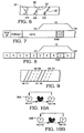
- FIGURE 7 illustrates in a simplistic way a section of recording tape upon which data has been previously written along with data retrieval information from a single data recorder A.
- FIGURE 8 depicts a section of the tape, again, simplistically shown, upon which a number of different blocks of data and data retrieval information have been written from, not one, but several data recorders, specifically recorders A, B, C and D.
- host computer 14 see FIGURE 1
- data block 5049 For purposes of convenience the block of data will be referred to as data block 5049.
- the transport assembly moves the tape to a position which places track 5049 in alignment with one of the read heads.
- the tape is then backspaced a distance sufficient to place the read head 36 several fields upstream of data block 5049, at which time the tape 26 is momentarily stopped, as indicated graphically at 0X in FIGURE 7.
- the tape is then caused to accelerate to its write/read or record speed indicated graphically at 1X during which time it first begins to retrieve data retrieval information and after which it retrieves the data itself from data block 5049. Thereafter, the tape is again stopped, as indicated at 0X'.
- FIGURE 9 illustrates eight tracks or one field starting with the first group of four tracks H0/H1, then H2/H3, then the second group of four tracks H4/H5, then H6/H7, this number of tracks corresponding to a field, which equates to two complete revolutions, with two read heads 36 per position and two positions.
- FIGURES 10A and 10B are read scan diagrams which are related in time, with FIGURE 10b shifted to the right relative to Figure 10A thereabove, and will be used to describe the read operation of the read heads 36.
- the unshaded overlapping ovals represent read operations for the respective heads, with the shaded overlapping ovals representing positions 180 degrees removed, without reading.
- the read heads are deflected by the automatic scan tracking system to enable a given pair of read heads to read a corresponding pair of successive groups of scan tracks without any displacement of the tape 26 relative to the scanning drum 24B.
- a first pair of read heads indicated as 36A in FIGURE 10A, reads the first two tracks H0/H1 of the first scan group of four tracks during the time that the scanner drum rotates a first one-half revolution, that is, during the first half-cycle of its first revolution.
- read heads 36A move 180 degrees without reading, as illustrated, whereupon, by reference to FIGURE 10B, the other pair of read heads, designated 36B, have moved laterally (that is along the line shown in FIGURE 3) a given increment to read the next two scan tracks H2/H3.
- read heads 36A Thereafter, 180 degrees later, read heads 36A have been deflected a given increment to be in a position to read the first two tracks H4/H5 of the next scan group of four tracks during the first half-cycle of the second revolution of the scanner, while the diametrically opposite pair of heads 36B are not reading. Thereafter, again 180 degrees later, read heads 36B have been deflected a given increment to be in a position to read the next two tracks H6/H7 of the next scan group of four tracks during the second half-cycle of the second revolution of the scanner, while the diametrically opposite pair of heads 36A are not reading, and then returning to their normal positions as indicated by the loop back line. After the second half cycle of the second revolution, read heads 36B are returned to their original undeflected position as indicated by the loop back line of FIGURE 10B.
- the scan tracks are read in groups of four scan tracks, the reason being that every fourth helical scan track has a mark (as part of its data retrieval information) that identifies it as the first scan of the field which enables ready determination of a particular location, at least on a relative basis, without reading the actual user data.
- the data must be placed in particular slots in the deshuffle buffer. There is a pipeline latency of about 10 milliseconds, which means the correct slot is not ascertainable until two scans have been read.
- FIGURE 11A the actual way in which data is written onto a segment of tape in the digital data storage system of the present invention is illustrated.
- Data is written in successive data blocks, which in the present embodiment are referred to as physical blocks, with a physical block occupying one double frame of data, or 32 helical scan tracks.
- EOR END OF RECORD
- host computer 14 instructs the data recorder to retrieve information from the data block starting at scan track 4127.
- the data recorder will proceed in the same manner described previously in conjunction with FIGURES 7 and 8. However, if it cannot accurately retrieve the data for the reasons described there, it is programmed to go into what may be referred to as a still framing mode. That is, it will locate a series of tracks immediately prior to the track 4127 and it will repeatedly still frame across those tracks in the manner described in conjunction with FIGURES 9, 10A and 10B, as diagrammatically illustrated by the still framing arrow 40 in FIGURE 11A.
- amble data which include scan tracks corresponding physically to the new data tracks that follow but include no actual user data, only data retrieval information.
- amble data blocks have the advantage of having been written by the very recorder used to write the subsequent data and at the same time. Since the amble data and physical block data have been written by the same recorder, adjustment or alignment of the read heads by amble data error rate examination provides accurate alignment for reading of data in the subsequent data blocks. This provides more accurate data retrieval information for the subsequent data than is the case where data retrieval information is taken from EOR blocks written by, for example, a different recorder at a different time.
- the still framing takes place in these amble blocks, as indicated in FIGURE 11B.
- data is requested later in the block, for example, starting at scan line 6217
- still framing within the amble blocks rather than the data blocks themselves. Specifically, there is a slight possibility that the still framing procedure may damage the tape. If it does so within the amble blocks as opposed to the data blocks there is no possibility of losing data.
- the present invention also contemplates the utilization of the slow motion techniques described in United States Patent 4,009,211 and 4,916,555.
- data retrieval information is retrieved not while the tape is motionless, as in FIGURES 11A and 11B and not while it is running at its write/read speed, as in FIGURES 7 and 8, but rather at a speed therebetween.
- less of the tape is taken up to accelerate to the speed required to retrieve the data retrieval information than is the case where retrieval takes place at the normal write/read speed.
- FIGURE 11C Three fields of data are illustrated there.
- the data retrieval information and data within field one are repeatedly read by means of still framing until the transport module and electronic module are able to reduce the errors associated with the damage to an acceptable level and thereby retrieve as much data as possible. Suitable circuitry is provided to that end.
- the tape is incrementally moved so that the process can be repeated at field two, field three and so on.
- the redundancy codes written onto the tracks with the data itself are quite helpful to minimize errors.
- FIGURE 12 illustrates still another feature of the present invention.
- U.S. Patents 4,009,211 and 4,916,555 teach the technique of video slow motion. This is the same as saying that the recorder can read the scan tracks accurately as the tape moves slower than its write/read speed.
- the present data recorder takes advantage of this feature. Specifically, this feature allows the present recorder to retrieve data retrieval information as the tape accelerates in speed from its still state to its write/read speed.
- the appropriate read head or read heads can repeatedly read Fields F1 and they can continue to do so as the tape begins to move.
- the heads can be controlled laterally to repeatedly read the next field, Field F2, and so, until the tape reaches its write/read speed. Note that as the speed of the tape increases, the number of times the read head can repeatedly read a given field decreases. Thus, it might only be able to read Field F3 three times and Field F4 two times, and so on. Nevertheless, in this way, it can retrieve information during the acceleration mode and thereby require less tape to retrieve data retrieval information.
- the transport module 20 releases scans in successive groups of four tracks, in successive sets of four scans, with the transport module 20 aligning the scans such that the LE pulse tagged scan is aligned with a field reference provided by the electronic module 18, as shown in tabular form below, with the numerical designation referring to a helical track scan number from a consecutive set of numbered tracks from "0" to "15"(representing four groups of tracks of four tracks each):
- This sequence is as follows:
- the above Table 1 correlates, in part, to FIGURE 12.
- the horizontal divisions divide the sets up into the uppermost section designated 1X which correlates to nominal operating speed, that is, the "1X" horizontal line portion of the curve of FIGURE 12.
- the next section designated ⁇ 1X correlates to the ramp-up portion of the curve of FIGURE 12, and correspondingly, the "0X” section corresponds to the stop position 0X of FIGURE 12.
- line numbering in the left hand column that is, (1) to (14).
- the flow of the sets of scans released from the transport module 18 flow from bottom to top in the above table and the transport module 18 aligns the scans such that the LE tagged scan aligns with a field reference provided by the electronic module 20.
- the scan groups shown at lines (14) to (11) are release first, and followed in successive order of decreasing line numbers thereafter. Since a scan group consists of four sets of four scans, a group under consideration will always consist of the first scan set H0-H3, the second scan set H4-H7, the third scan set H8-H11, and the fourth scan set H12-H15.
- this error checking by the electronic module includes examining the C1/C2 code error rate. After the ECC, the data flows to the sub area for scan number decoding to provide information to the electronic module as to the set of scans currently under scrutiny.
- the multiplexer is under software control and decides, based on certain decision criteria, at which of the four slots (one scan set per slot) to point (arrows from the MUX) the data within the shuffle buffer 22.
- the leftmost column enclosed in rectangles in the table is the first scan set, the next column the second scan set, and so on.
- the decision criteria for the pointer is as follows: (1) if the error checking of the first scan set is beyond the error limit, adjust the head deflection and scan again (repeating if necessary); (2) if the error rate of the first scan set is within limits, go to the next group, if the subsequent scan of a complete group of four successive scan sets includes the correct scan number, go to the next group.
- still framing is utilized on a single scan or field until the AST curvature and offset has been established to compensate for one of the conditions discussed in connection with FIGURE 6 (this entails making head deflection adjustments.)
- the transport equalizer is also adjusted until the electronic module 20 provides an error rate which is acceptable, with that scan then being latched into the first scan of the shuffle buffer 22. Then the next scan is read into the next shuffle buffer 22 slot, one position and scan at a time.
- the shuffle buffer 22 is selectively filled with data having successive scan numbers, with error correction and head deflection adjustment being accomplished during ramp up. Effectively, error rate information during still framing or on start up from standstill provides information to be used to tell if the data is good, and to compensate until it is acceptable.
Landscapes
- Engineering & Computer Science (AREA)
- Signal Processing (AREA)
- Multimedia (AREA)
- General Engineering & Computer Science (AREA)
- Signal Processing For Digital Recording And Reproducing (AREA)
- Management Or Editing Of Information On Record Carriers (AREA)
- Apparatus For Radiation Diagnosis (AREA)
- Indexing, Searching, Synchronizing, And The Amount Of Synchronization Travel Of Record Carriers (AREA)
Claims (10)
- Verfahren zum Aufzeichnen digitaler Daten und einer zugeordneten Daten-Wiedergewinnungsinformation auf einem Magnetband (26) und zum Wiedergewinnen von diesen, wobei die digitalen Daten und die zugeordnete Daten-Wiedergewinnungsinformation mit einer Nenngeschwindigkeit einer Längsbewegung des Bandes geschrieben werden und wobei die digitalen Daten in einer Abfolge von Helical-Scan-Spuren geschrieben werden, wobei die digitalen Daten mittels einer Abtastanordnung wiedergewonnen werden, die eine sich drehende Abtasteinrichtung (24), um die das Band schraubenförmig gewickelt ist, und Wiedergabeköpfe (34) aufweist, von denen die effektiven Positionen in einem Sinn senkrecht zu den Spuren seitlich versetzbar sind, gekennzeichnet durch:Aufzeichnen verschiedener Teile der digitalen Daten und der zugeordneten Daten-Wiedergewinnungsinformation mittels verschiedener Datenrecorder (A, B, C, D);Wiedergewinnen der Daten-Wiedergewinnungsinformation aus einem Abschnitt des Bandes, während das Band entweder stationär ist oder auf die Nenngeschwindigkeit beschleunigt wird;Bestimmen der Fehlerrate der so wiedergewonnenen Daten-Wiedergewinnungsinformation;Vergleichen der Fehlerrate mit einer zuvor gebildeten Fehlerratengrenze;Einstellen der Abtasteinrichtung, falls die Fehlerrate die zuvor gebildete Fehlerratengrenze überschreitet, so daß die Fehlerrate verringert wird; unddanach Wiedergewinnen der digitalen Daten, wenn sich das Band mit der Nenngeschwindigkeit bewegt.
- Verfahren nach Anspruch 1 und ferner aufweisend das Einstellen des Ausgleichs der Daten-Wiedergewinnungsinformation zum weiteren Verringern der Fehlerrate.
- Verfahren nach Anspruch 1 oder 2, wobei die Daten-Wiedergewinnungsinformation von dem Abschnitt wiederholt wiedergewonnen wird und die Abtasteinrichtung eingestellt wird, bis die Fehlerrate geringer als die Fehlerratengrenze ist.
- Verfahren nach einem vorhergehenden Anspruch, wobei die Daten-Wiedergewinnungsinformation ein Vierfachframesignal (QF), ein Doppelframesignal (DF), ein Einfachframesignal (SF) und ein Servosignal (SVO) aufweist.
- Verfahren nach Anspruch 1, wobei die Daten-Wiedergewinnungsinformation aus dem Segment wiedergewonnen wird, während das Band nicht bewegt wird, indem bewirkt wird, daß die Abtasteinrichtung Helical-Scan-Spuren innerhalb des Abschnitts wiederholt abtastet.
- Verfahren nach einem der Ansprüche 1 bis 4, wobei die Daten-Wiedergewinnungsinformation aus dem Abschnitt wiedergewonnen wird, während das Band beschleunigt wird, indem bewirkt wird, daß die Abtastanordnung eine Abfolge von Gruppen der Spuren innerhalb des Abschnitts wiederholt abtastet.
- Verfahren nach Anspruch 1, wobei die digitalen Daten in Gruppen der aufeinanderfolgenden Helical-Scan-Spuren zusammen mit einer Daten-Wiedergewinnungsinformation geschrieben werden und wobei ferner die Daten-Wiedergewinnungsinformation auf einer der Spuren in jeder Gruppe die Spur als die erste Spur in der Gruppe identifiziert und wobei jede Gruppe der Daten-Wiedergewinnungsinformation bei entsprechenden Adreßstellen in Erwiderung auf die identifizierte erste Spur gespeichert wird.
- Verfahren nach einem vorhergehenden Anspruch, wobei das Einstellen der Abtasteinrichtung das Einstellen der seitlichen Ablenkungen der Köpfe relativ zu den Spuren aufweist.
- Verfahren zum Betreiben einer Digitaldaten-Aufzeichnungseinrichtung mit einer automatischen Abtastnachführung zum Wiedergewinnen digitaler Daten, die zusammen mit einer Daten-Wiedergewinnungsinformation auf in Längsrichtung aufeinanderfolgende Helical-Scan-Spuren in einem Aufzeichnungsband (26) geschrieben sind, wobei die Aufzeichnungseinrichtung eine sich drehende Abtasteinrichtung (24) und Wandlerköpfe (34) aufweist, von denen die effektiven Positionen seitlich in einem Sinn senkrecht zu den Spuren einstellbar sind, wobei die Aufzeichnungseinrichtung zum Wiedergewinnen aufgezeichneter digitaler Daten von dem Aufzeichnungsband zusammen mit der Daten-Wiedergewinnungsinformation mittels der sich drehenden Abtastanordnung betreibbar ist, während sich das Aufzeichnungsband in Längsrichtung mit einer normalen Nenngeschwindigkeit bewegt, gekennzeichnet durch das Bestimmen einer Fehlerrate in der Daten-Wiedergewinnungsinformation, wenn die Aufzeichnungseinrichtung einen aufgezeichneten Abschnitt entweder wiedergibt, wenn das Band stationär ist oder wenn das Band auf eine Nenngeschwindigkeit beschleunigt wird; Vergleichen der Fehlerrate mit einem vorbestimmten Schwellenwert; Wiederholen der Wiedergewinnung der Daten-Wiedergewinnungsinformation und Einstellen der Abtasteinrichtung mittels des Einstellens von Ablenkungen der Köpfe relativ zu den Spuren bis die Fehlerrate geringer als der Schwellenwert ist; und Ermöglichen der Wiedergewinnung der aufgezeichneten digitalen Daten bei einer normalen Geschwindigkeit des Bandes.
- Verfahren nach Anspruch 9 und ferner aufweisend das Einstellen des Ausgleichens der Daten-Wiedergewinnungsinformation zum weiteren Herabsetzen der Fehlerrate.
Applications Claiming Priority (2)
| Application Number | Priority Date | Filing Date | Title |
|---|---|---|---|
| US86726892A | 1992-04-10 | 1992-04-10 | |
| US867268 | 1992-04-10 |
Publications (3)
| Publication Number | Publication Date |
|---|---|
| EP0565367A2 EP0565367A2 (de) | 1993-10-13 |
| EP0565367A3 EP0565367A3 (de) | 1994-12-14 |
| EP0565367B1 true EP0565367B1 (de) | 1997-12-10 |
Family
ID=25349464
Family Applications (1)
| Application Number | Title | Priority Date | Filing Date |
|---|---|---|---|
| EP93302746A Expired - Lifetime EP0565367B1 (de) | 1992-04-10 | 1993-04-07 | Ein zur Datenrückgewinnung Standbildtechniken benutzendes Datenaufnahmeverfahren |
Country Status (8)
| Country | Link |
|---|---|
| US (1) | US5729400A (de) |
| EP (1) | EP0565367B1 (de) |
| JP (1) | JPH0652660A (de) |
| KR (1) | KR100255919B1 (de) |
| CN (1) | CN1085341A (de) |
| AT (1) | ATE161117T1 (de) |
| DE (1) | DE69315611T2 (de) |
| MX (1) | MX9302025A (de) |
Families Citing this family (3)
| Publication number | Priority date | Publication date | Assignee | Title |
|---|---|---|---|---|
| US6913765B2 (en) * | 2001-03-21 | 2005-07-05 | Scimed Life Systems, Inc. | Controlling resorption of bioresorbable medical implant material |
| JP2013156798A (ja) * | 2012-01-30 | 2013-08-15 | Kddi Corp | 記憶装置、アクセスパターンの秘匿方法およびプログラム |
| CN112820325B (zh) * | 2021-01-27 | 2022-04-15 | 天津航大雄英航空工程有限公司 | 一种飞参记录器破损磁带数据读取的掩膜方法 |
Family Cites Families (12)
| Publication number | Priority date | Publication date | Assignee | Title |
|---|---|---|---|---|
| US4916555A (en) * | 1976-03-19 | 1990-04-10 | Ampex Corporation | Method and apparatus for producing time base altered effects in data recording and reproducing apparatus |
| US4099211A (en) * | 1976-09-13 | 1978-07-04 | Ampex Corporation | Positionable transducing mounting structure and driving system therefor |
| US4215362A (en) * | 1978-03-23 | 1980-07-29 | Ampex Corporation | Track selection method and apparatus |
| US4308560A (en) * | 1978-03-23 | 1981-12-29 | Ampex Corporation | Method of operating a signal reproducing apparatus for effecting synchronous reproduction of recorded signals |
| US4494153A (en) * | 1978-03-23 | 1985-01-15 | Ampex Corporation | Method of operating a signal reproduction apparatus for effecting synchronous reproduction of recorded signals |
| US4447835A (en) * | 1982-01-11 | 1984-05-08 | Sony Corporation | Method and apparatus for single frame recording on video tape |
| US4751586A (en) * | 1982-09-17 | 1988-06-14 | Ampex Corporation | Rotary head tape transport servo system having high speed servo lock capability |
| US4947272A (en) * | 1987-03-30 | 1990-08-07 | Pioneer Electronic Corporation | Signal reproducing device which offsets the tracking error signal for a digital tape player |
| JPS63263656A (ja) * | 1987-04-20 | 1988-10-31 | Sanyo Electric Co Ltd | Pcm信号再生装置のトラツキングサ−ボ回路 |
| DE3805436A1 (de) * | 1988-02-22 | 1989-08-31 | Bosch Gmbh Robert | Verfahren zur wiedergabe von datensignalen |
| US4872073A (en) * | 1988-09-02 | 1989-10-03 | Ampex Corporation | Apparatus for playback of magnetically recorded data having a variable input rate |
| US5335119A (en) * | 1992-02-28 | 1994-08-02 | Ampex Corporation | Data recording system having unique nonrecording detection |
-
1993
- 1993-04-07 DE DE69315611T patent/DE69315611T2/de not_active Expired - Lifetime
- 1993-04-07 EP EP93302746A patent/EP0565367B1/de not_active Expired - Lifetime
- 1993-04-07 MX MX9302025A patent/MX9302025A/es unknown
- 1993-04-07 AT AT93302746T patent/ATE161117T1/de not_active IP Right Cessation
- 1993-04-09 KR KR1019930006070A patent/KR100255919B1/ko not_active Expired - Fee Related
- 1993-04-10 CN CN93105794A patent/CN1085341A/zh active Pending
- 1993-04-12 JP JP5084964A patent/JPH0652660A/ja active Pending
-
1995
- 1995-07-20 US US08/504,822 patent/US5729400A/en not_active Expired - Lifetime
Also Published As
| Publication number | Publication date |
|---|---|
| EP0565367A3 (de) | 1994-12-14 |
| MX9302025A (es) | 1994-07-29 |
| JPH0652660A (ja) | 1994-02-25 |
| DE69315611T2 (de) | 1998-07-16 |
| EP0565367A2 (de) | 1993-10-13 |
| KR100255919B1 (ko) | 2000-05-01 |
| CN1085341A (zh) | 1994-04-13 |
| US5729400A (en) | 1998-03-17 |
| KR930022271A (ko) | 1993-11-23 |
| ATE161117T1 (de) | 1997-12-15 |
| DE69315611D1 (de) | 1998-01-22 |
Similar Documents
| Publication | Publication Date | Title |
|---|---|---|
| EP0702823B1 (de) | Gerät und verfahren zur wiedergewinnung von daten einer verformten spur | |
| US5191491A (en) | Method and apparatus for reading distorted helical stripes | |
| JPH05500582A (ja) | ら旋走査記録器のためのサーボトラッキング方法及びら旋走査記録器 | |
| CA1235221A (en) | Digital video recording | |
| US5276566A (en) | Recording/reading high density data tracks with backward compatibility | |
| US4774605A (en) | Rotary head type digital signal playback | |
| US4003086A (en) | Dynamic loop gain alteration for data retrieval | |
| EP0488373A2 (de) | Magnetband-Aufnahme/Wiedergabevorrichtung und Verfahren | |
| US6101060A (en) | Method and apparatus for reducing data loss errors in a magnetic tape device | |
| US7813069B2 (en) | Method and apparatus for controlling motion of storage media | |
| EP0565367B1 (de) | Ein zur Datenrückgewinnung Standbildtechniken benutzendes Datenaufnahmeverfahren | |
| EP0833329A2 (de) | Wiedergabegerät zur Zwischenspeicherung von wiedergegebenen Daten in einem Speicher | |
| EP0671735B1 (de) | Verfahren und Gerät für die Bewegungssteuerung von Aufzeichnungsmedien | |
| US5323276A (en) | Error removal method for a multi-track tape recorder system | |
| EP0402912B1 (de) | Plattenspeichersystem | |
| JPH0551981B2 (de) | ||
| JP3933133B2 (ja) | データ再生装置及びデータ再生方法 | |
| JPH03116404A (ja) | 回転ヘッド型再生装置 | |
| JP3250449B2 (ja) | 磁気テープ制御装置 | |
| JP2550202B2 (ja) | 回転ヘッド型再生装置 | |
| EP0831481A1 (de) | Verfahren und Gerät zur Datenspeicherung | |
| JPS63102006A (ja) | 磁気記録再生装置 | |
| JPS63298847A (ja) | テ−プ送り方式 | |
| JPS6386105A (ja) | 磁気記録再生装置 | |
| JPH0676478A (ja) | 磁気ディスク装置 |
Legal Events
| Date | Code | Title | Description |
|---|---|---|---|
| PUAI | Public reference made under article 153(3) epc to a published international application that has entered the european phase |
Free format text: ORIGINAL CODE: 0009012 |
|
| AK | Designated contracting states |
Kind code of ref document: A2 Designated state(s): AT CH DE FR GB IT LI NL |
|
| PUAL | Search report despatched |
Free format text: ORIGINAL CODE: 0009013 |
|
| AK | Designated contracting states |
Kind code of ref document: A3 Designated state(s): AT CH DE FR GB IT LI NL |
|
| 17P | Request for examination filed |
Effective date: 19950613 |
|
| 17Q | First examination report despatched |
Effective date: 19950918 |
|
| GRAG | Despatch of communication of intention to grant |
Free format text: ORIGINAL CODE: EPIDOS AGRA |
|
| RTI1 | Title (correction) | ||
| GRAH | Despatch of communication of intention to grant a patent |
Free format text: ORIGINAL CODE: EPIDOS IGRA |
|
| GRAH | Despatch of communication of intention to grant a patent |
Free format text: ORIGINAL CODE: EPIDOS IGRA |
|
| GRAA | (expected) grant |
Free format text: ORIGINAL CODE: 0009210 |
|
| AK | Designated contracting states |
Kind code of ref document: B1 Designated state(s): AT CH DE FR GB IT LI NL |
|
| PG25 | Lapsed in a contracting state [announced via postgrant information from national office to epo] |
Ref country code: NL Free format text: LAPSE BECAUSE OF FAILURE TO SUBMIT A TRANSLATION OF THE DESCRIPTION OR TO PAY THE FEE WITHIN THE PRESCRIBED TIME-LIMIT Effective date: 19971210 Ref country code: LI Free format text: LAPSE BECAUSE OF FAILURE TO SUBMIT A TRANSLATION OF THE DESCRIPTION OR TO PAY THE FEE WITHIN THE PRESCRIBED TIME-LIMIT Effective date: 19971210 Ref country code: IT Free format text: LAPSE BECAUSE OF FAILURE TO SUBMIT A TRANSLATION OF THE DESCRIPTION OR TO PAY THE FEE WITHIN THE PRESCRIBED TIME-LIMIT;WARNING: LAPSES OF ITALIAN PATENTS WITH EFFECTIVE DATE BEFORE 2007 MAY HAVE OCCURRED AT ANY TIME BEFORE 2007. THE CORRECT EFFECTIVE DATE MAY BE DIFFERENT FROM THE ONE RECORDED. Effective date: 19971210 Ref country code: CH Free format text: LAPSE BECAUSE OF FAILURE TO SUBMIT A TRANSLATION OF THE DESCRIPTION OR TO PAY THE FEE WITHIN THE PRESCRIBED TIME-LIMIT Effective date: 19971210 Ref country code: AT Free format text: LAPSE BECAUSE OF FAILURE TO SUBMIT A TRANSLATION OF THE DESCRIPTION OR TO PAY THE FEE WITHIN THE PRESCRIBED TIME-LIMIT Effective date: 19971210 |
|
| REF | Corresponds to: |
Ref document number: 161117 Country of ref document: AT Date of ref document: 19971215 Kind code of ref document: T |
|
| REG | Reference to a national code |
Ref country code: CH Ref legal event code: EP |
|
| REF | Corresponds to: |
Ref document number: 69315611 Country of ref document: DE Date of ref document: 19980122 |
|
| ET | Fr: translation filed | ||
| REG | Reference to a national code |
Ref country code: GB Ref legal event code: 732E |
|
| NLV1 | Nl: lapsed or annulled due to failure to fulfill the requirements of art. 29p and 29m of the patents act | ||
| REG | Reference to a national code |
Ref country code: CH Ref legal event code: PL |
|
| PLBE | No opposition filed within time limit |
Free format text: ORIGINAL CODE: 0009261 |
|
| STAA | Information on the status of an ep patent application or granted ep patent |
Free format text: STATUS: NO OPPOSITION FILED WITHIN TIME LIMIT |
|
| 26N | No opposition filed | ||
| REG | Reference to a national code |
Ref country code: GB Ref legal event code: IF02 |
|
| PGFP | Annual fee paid to national office [announced via postgrant information from national office to epo] |
Ref country code: FR Payment date: 20110426 Year of fee payment: 19 Ref country code: DE Payment date: 20110330 Year of fee payment: 19 |
|
| PGFP | Annual fee paid to national office [announced via postgrant information from national office to epo] |
Ref country code: GB Payment date: 20110406 Year of fee payment: 19 |
|
| GBPC | Gb: european patent ceased through non-payment of renewal fee |
Effective date: 20120407 |
|
| REG | Reference to a national code |
Ref country code: FR Ref legal event code: ST Effective date: 20121228 |
|
| PG25 | Lapsed in a contracting state [announced via postgrant information from national office to epo] |
Ref country code: GB Free format text: LAPSE BECAUSE OF NON-PAYMENT OF DUE FEES Effective date: 20120407 |
|
| REG | Reference to a national code |
Ref country code: DE Ref legal event code: R119 Ref document number: 69315611 Country of ref document: DE Effective date: 20121101 |
|
| PG25 | Lapsed in a contracting state [announced via postgrant information from national office to epo] |
Ref country code: FR Free format text: LAPSE BECAUSE OF NON-PAYMENT OF DUE FEES Effective date: 20120430 |
|
| PG25 | Lapsed in a contracting state [announced via postgrant information from national office to epo] |
Ref country code: DE Free format text: LAPSE BECAUSE OF NON-PAYMENT OF DUE FEES Effective date: 20121101 |