EP0050293A2 - Vorrichtung zur variablen Verstärkung der elastischen Abstützkräfte in beliebigen Partialbereichen eines Liegemöbel-Lattenrosts - Google Patents
Vorrichtung zur variablen Verstärkung der elastischen Abstützkräfte in beliebigen Partialbereichen eines Liegemöbel-Lattenrosts Download PDFInfo
- Publication number
- EP0050293A2 EP0050293A2 EP81108226A EP81108226A EP0050293A2 EP 0050293 A2 EP0050293 A2 EP 0050293A2 EP 81108226 A EP81108226 A EP 81108226A EP 81108226 A EP81108226 A EP 81108226A EP 0050293 A2 EP0050293 A2 EP 0050293A2
- Authority
- EP
- European Patent Office
- Prior art keywords
- spring
- slats
- female connectors
- elastic
- load
- Prior art date
- Legal status (The legal status is an assumption and is not a legal conclusion. Google has not performed a legal analysis and makes no representation as to the accuracy of the status listed.)
- Granted
Links
- 230000002787 reinforcement Effects 0.000 title claims description 4
- 230000008878 coupling Effects 0.000 claims abstract description 17
- 238000010168 coupling process Methods 0.000 claims abstract description 17
- 238000005859 coupling reaction Methods 0.000 claims abstract description 17
- 238000009825 accumulation Methods 0.000 claims description 2
- 239000013013 elastic material Substances 0.000 claims description 2
- 238000004873 anchoring Methods 0.000 claims 1
- 210000001217 buttock Anatomy 0.000 abstract description 2
- 239000000463 material Substances 0.000 description 2
- 206010006895 Cachexia Diseases 0.000 description 1
- 230000037396 body weight Effects 0.000 description 1
- 238000010276 construction Methods 0.000 description 1
- 230000007812 deficiency Effects 0.000 description 1
- 230000001419 dependent effect Effects 0.000 description 1
- 208000026500 emaciation Diseases 0.000 description 1
- 239000004033 plastic Substances 0.000 description 1
- 229920003023 plastic Polymers 0.000 description 1
- 230000035935 pregnancy Effects 0.000 description 1
- 230000009257 reactivity Effects 0.000 description 1
- 230000001105 regulatory effect Effects 0.000 description 1
- 230000003068 static effect Effects 0.000 description 1
- 239000000725 suspension Substances 0.000 description 1
Images
Classifications
-
- A—HUMAN NECESSITIES
- A47—FURNITURE; DOMESTIC ARTICLES OR APPLIANCES; COFFEE MILLS; SPICE MILLS; SUCTION CLEANERS IN GENERAL
- A47C—CHAIRS; SOFAS; BEDS
- A47C23/00—Spring mattresses with rigid frame or forming part of the bedstead, e.g. box springs; Divan bases; Slatted bed bases
- A47C23/06—Spring mattresses with rigid frame or forming part of the bedstead, e.g. box springs; Divan bases; Slatted bed bases using wooden springs, e.g. of slat type ; Slatted bed bases
- A47C23/062—Slat supports
- A47C23/068—Slat supports with additional supports between the ends of the slats
Definitions
- the present invention relates to a device for variable reinforcement of the elastic support forces in any partial areas of reclining furniture with spring bars arranged transversely to the reclining furniture axis, for the purpose of improving the load-bearing behavior while simultaneously reducing the space between the female and male bars in the areas of greatest load.
- the known reclining furniture provided with transverse spring slats which are also referred to as LSUtlicbuch, have an elastically deformable lying surface that bends depending on the local load and intercepts the load with a corresponding support force opposing the load.
- This elastic reactivity of the bed surface which is sometimes also referred to as spring hardness, is now the same size in the known bed furniture over the entire bed surface, although the load on the bed surface is undoubtedly very different locally.
- the greatest load generally occurs in the central area of the lying surface, ie at the support points of the buttocks and hips, while the end areas support the head and feet are hardly subject to noteworthy loads.
- people can change their body weight considerably over time and that the load conditions of a bed are subject to considerable fluctuations, for example after an emaciation regimen or during pregnancy.
- the object of the present invention to provide a device for zone reinforcement on reclining furniture with spring slats, which allows any zones of the lying surface, but in particular the most stressed middle zone, to be varied at will with regard to their elastic supporting force, in order to thus prevail To be able to adapt stress conditions in the sense of physiologically correct lying.
- the device should not require any damage to the adjacent female connectors for its attachment and, moreover, should bring the additional advantage that it contributes to the protection of the top mattress and its better carrying behavior.
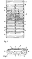
- Fig. 1 shows a slatted frame designated in its entirety with 1, which is composed of two longitudinal frames 2 and a number of transverse spring slats 3.
- the female connectors 3 are designed in a known manner as multi-layer wooden springs and are based on rubber-elastic support bodies 4, which are anchored to the inner surfaces of the longitudinal frames 2. On each pair of these support bodies 4, as the figure shows, there are two spring strips 3 which are arranged at a mutual distance and are thus assigned to the support bodies in pairs. Details . this construction results from the CH patent application No. 12002/77.
- a known central belt M is arranged in the central region of the slatted frame.
- the mutually adjacent pairs of female connectors 3 are at a mutual distance a.
- This distance must be chosen to be relatively large for wooden spring gratings, because if the pitch is too narrow, the spring hardness would be exceptionally high.
- the waiter, not shown mattress is pressed with its underside into the space between adjacent pairs of female connectors and there is prematurely worn or damaged under the influence of sleep movements. Correcting this deficiency is one of the objects that the present invention is intended to solve.
- this device comprises two rubber-elastic coupling members 5 and an additional spring slat Z.
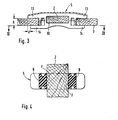
- the coupling member 5 is a profile body which has two longitudinal strips 6/7, which are connected to one another by transverse webs 8, 9. In this way, there is a through opening 10 in the central region and an open recess 11/12 at each of the two ends.
- the height h of these recesses corresponds approximately to the thickness of the wooden spring slats 3 (FIG. 3), so that the coupling element 5 can be arranged like a bridge between two pairs of wooden spring strips 3 and secured with the recesses 11, 12 on the adjacent wooden spring strips.
- the two retaining lips 13 and 14 delimiting the recesses are of different lengths (compare length difference d in FIG.
- the recess can be installed 11 over a wooden female connector and then snap the coupling element from above with the shorter lip 14 over the other wooden female connector.
- the coupling element which should consist of a tough, rubber-elastic material with high flexural strength, is thus securely anchored in the space between two pairs of wooden slats.
- the through opening 10 is dimensioned such that the additional spring slat designated Z in FIG. 1 can just be inserted through the opening and is then held firmly in the same.
- the inner walls of the through opening 10 are preferably narrowed slightly on one side or on both sides, as is shown in particular in FIG. 4.
- the webs 8 and 9 are slightly cambered on the contact surfaces F on the additional spring slat Z in the exemplary embodiment.
- the device will accordingly be fitted with any number of additional spring slats Z in the area of the heaviest load and its elastic behavior can be adapted to individual needs by regulating the distance c. Since the additional spring slats Z are anchored to the spring strips 3 via the coupling members 5, the suspension properties of the latter will also change.
- the entire support area B (FIG. 1) can thus be "hardened", while individual areas within this area can either be made particularly hard or more resilient.
- rubber-elastic used in the present context is to be understood to include all materials, in particular also plastics, which can be compared to rubber on account of their elasticity behavior.
- the rubber elasticity based on the material itself is therefore the formula elasticity, e.g. a coil spring, opposite.
Landscapes
- Mattresses And Other Support Structures For Chairs And Beds (AREA)
- Springs (AREA)
Abstract
Description
- Die vorliegende Erfindung betrifft eine Vorrichtung zur variablen Verstärkung der elastischen Abstützkräfte in beliebigen Partialbereichen von Liegemöbeln mit quer zur Liegemöbelachse angeordneten Federlelsten, zwecks Verbesserung des Tragverhaltens unter gleichzeitiger Verringerung des Federleisten-Zwischenraumes im Bereiche grösster Belastung.
- Die bekannten, mit quer verlaufenden Federleisten versehenen Liegemöbel, welche auch als Lättlicbuch bezeichnet werden, weisen eine elastisch verformbare Liegefläche auf, die sich je nach der lokalen Belastung durchbiegt und die Belastung mit einer entsprechenden, der Belastung entgegengerichteten Abstützkraft abfängt. Diese elastische Reaktionsfähigkeit der'Liegefläche, die zuweilen auch als Federhärte bezeichnet wird, ist nun bei den bekannten Liegemöbeln auf der gesamten Liegefläche gleich gross, obwohl die Belastung der Liegefläche zweifellos lokal sehr unterschiedlich ist. So muss einerseits berücksichtigt werden, dass die grösste Belastung im allgemeinen etwa im Mittelbereich der Liegefläche, d.h. an den Abstützstellen von Gesäss und Hüfte, auftritt, während die Endbereiche zur Abstützung von Kopf und Füssen kaum nennenswerten Belastungen unterworfen sind. Hinzu kommt, dass der Mensch im Laufe der Zeit sein Körpergewicht ganz erheblich zu verändern vermag und dass die Belastungsverhältnisse eines Bettes beispielsweise nach einer Abmagerungskur oder während einer Schwangerschaft beträchtlichen Schwankungen unterworfen sind.
- Es ist somit die Aufgabe der vorliegenden Erfindung, eine Vorrichtung zur Zonenverstärkung an Liegemöbeln mit Federleisten zu schaffen, die es gestattet, beliebige Zonen der Liegefläche, insbesondere aber die meistbelastete Mittelzone, nach Belieben bezüglich ihrer elastischen Abstützkraft zu variieren, um sie somit den gerade herrschenden Belastungsverhältnissen im Sinne physiologisch richtigen Liegens anpassen zu können. Die Vorrichtung soll ferner zu ihrer Befestigung keinerlei Beschädigung der angrenzenden Federleisten erfordern und im übrigen' den zusätzlichen Vorteil mit sich bringen, dass sie zur' Schonung der Obermatratze und deren besserem Tragverhalten beiträgt.
- Diese Aufgabe wird dank der im unabhängigen Anspruch 1 definierten Merkmalskombination gelöst. Ausführungsvarianten des Erfindungsgegenstandes sind in den abhängigen Ansprüchen definiert.
- Nachstehend wird anhand der beiliegenden Zeichnung ein Ausführungsbeispiel des Erfindungsgegenstandes beschrieben.
- Fig. 1 ist eine Draufsicht auf einen für ein Liegemöbel bestimmten Lattenrost,
- Fig. 2 ist eine Perspektivansicht eines der elastischen Kupplungsorgane,
- Fig. 3 zeigt das montierte Kupplungsorgan in Seitenansicht und
- Fig. 4 ist ein Schnitt längs der Linie IV-IV aus Fig. 3.
- Fig. 1 zeigt einen in seiner Gesamtheit mit 1 bezeichneten Lattenrost, welcher sich aus zwei Längszargen 2 und einer Anzahl quer verlaufender Federleisten 3 zusammensetzt. Die Federleisten 3 sind in bekannter Weise als mehrschichtige Holzfedern ausgebildet und stützen sich auf gummielastische Stützkörper 4, die an den Innenflächen der Längszargen 2 verankert sind. Auf je einem Paar dieser Stützkörper 4 ruhen, wie die Figur zeigt, zwei in gegenseitigem Abstand angeordnete Federleisten 3, die somit paarweise den Stützkörpern zugeordnet sind. Einzelheiten . dieser Konstruktion ergeben sich aus dem CH-Patentgesuch Nr. 12002/77.
- Ein bekannter Mittelgurt M ist im Mittelbereich des Lattenrostes angeordnet.
- Die einander benachbarten Federleistenpaare 3 befinden sich in gegenseitigem Abstand a. Dieser Abstand muss bei Holzfederrosten relativ gross gewählt werden, da sich bei zu enger Teilung eine aussergewöhnlich hohe Federhärte ergäbe. Aufgrund des grossen Abstandes a besteht jedoch das Risiko, dass die nicht dargestellte Obermatratze mit ihrer Unterseite in den Zwischenraum zwischen einander benachbarten Federleistenpaaren eingedrückt wird und dort unter dem Einfluss der Schlafbewegungen frühzeitig abgenutzt bzw. beschädigt wird. Die Behebung dieses Mangels ist eine der Aufgaben, die durch die vorliegende Erfindung gelöst werden sollen.
- In einem mit B bezeichneten Belastungsbereich des Lattenrostes, in welchem erfahrungsgemäss die grössten statischen und dynamischen Belastungen auftreten, sind in den Zwischenräumen zweier benachbarter Federleistenpaare 3 Vorrichtungen angeordnet, welche es nicht nur gestatten, diese Zwischenräume unter weitgehender Schonung der Obermatratze zu überbrücken, sondern die eine gezielte, in bezug auf lokale Verteilung und Intensität der Federhärte variable Anpassung der elastischen Abstützbedingungen an bestimmte Bedarfsfälle zulassen. Diese Vorrichtung umfasst in jedem der genannten Zwischenräume zwei gummielastische Kupplungsorgane 5 sowie eine Zusatzfederlatte Z.
- Wie Fig. 2 zeigt, ist das Kupplungsorgan 5 ein Profilkörper, welcher zwei Längsleisten 6/7 aufweist, die durch Querstege 8, 9 miteinander verbunden sind. Auf diese Weise ergibt sich im Mittelbereich eine Durchgangsöffnung 10 und an den beiden Enden je eine offene Ausnehmung 11/12. Die Höhe h dieser Ausnehmungen entspricht in etwa der Dicke der Holzfederlatten 3 (Fig. 3), so dass sich das Kupplungsorgan 5 nach Art einer Brücke zwischen zwei Holzfederleistenpaaren 3 anordnen und mit den Ausnehmungen 11, 12 an den angrenzenden Holzfederleisten sichern lässt. Im Hinblick auf eine einfache Handhabung beim Ein- und Ausbau sind die beiden die Ausnehmungen begrenzenden Haltelippen 13 und 14 (Fig. 3) von unterschiedlicher Länge (vergleiche Längendifferenz d in Fig. 3), in jedem Falle aber kürzer als die Gesamtbreite einer Federleiste 3. Bei der Montage kann man somit beispielsweise die Ausnehmung 11 über eine Holzfederleiste stecken und das Kupplungsorgan dann von oben her mit der kürzeren Lippe 14 über die andere Holzfederleiste schnappen lassen. Das Kupplungsorgan, das aus einem zähen, gummielastischen Werkstoff hoher Biegefestigkeit bestehen sollte, ist damit sicher im Zwischenraum zwischen zwei Holzfederleistenpaaren verankert.
- Die Durchgangsöffnung 10 ist so bemessen, dass sich die in Fig. 1 mit Z bezeichnete Zusatzfederlatte knapp durch die Oeffnung hindurchstecken lässt und dann satt in derselben gehalten-ist. Vorzugsweise sind die Innenwände der Durchgangsöffnung 10 nach einer Seite oder nach beiden Seiten leicht verengt, wie dies insbesondere Fig. 4 zeigt. Die Stege 8 und 9 sind bei dem Ausführungsbeispiel an den Anlageflächen F an der Zusatzfederlatte Z leicht bombiert.
- Bei der Anordnung nach Fig. l sind vier Zusatzfederlatten Z mittels vier Paaren von Kupplungsorganen 5 vorgesehen. Der gegenseitige Abstand c der Kupplungsorgane 5 lässt sich leicht variieren, was ebenfalls einen Einfluss auf das elastische Abstützverhalten der betreffenden Zusatzfederleiste Z ausübt.
- In der praktischen Anwendung der beschriebenen Vorrichtung wird man demgemäss in dem Bereich stärkster Belastung eine beliebige Anzahl von Zusatzfederlatten Z anbringen und deren elastisches Verhalten durch Regulie-ren des Abstandes c,den individuellen Bedürfnissen anpassen. Da die Zusatzfederlatten Z über die Kupplungsorgane 5 an den Federleisten 3 verankert sind, werden sich auch die Federungseigenschaften der letzteren verändern. Somit lässt sich der gesamte Abstützbereich B (Fig. 1) "verhär- - ten", während innerhalb dieses Bereiches wiederum einzelne Stellen entweder besonders hart oder nachgiebiger gestaltet werden können.
- Gerade in diesem Belastungsbereich B ist es auch besonders wichtig, dass die Obermatratze nicht in die Zwischenräume zwischen zwei Federleistenpaaren 3 gepresst und dort beschädigt werden kann. Dies wird durch die Anordnung der Zusatzfederlatten wirksam verhindert. Eine auf der Oberfläche der Kupplungsorgane 5 angeordnete Profilierung P (Fig. 2) verhindert das unerwünschte Verrutschen der Obermatratze sowie die Ansammlung von Feuchtigkeit.
- Der im vorliegenden Zusammenhang verwendete Ausdruck "gummielastisch" ist so zu verstehen, dass er sämtliche Materialien, insbesondere auch Kunststoffe umfasst, die sich aufgrund ihres Elastizitätsverhaltens mit dem Gummi vergleichen lassen. Der auf dem Werkstoff selbst beruhenden Gummielastizität steht somit die Formelastizität, z.B. einer Schraubenfeder, gegenüber.
Claims (5)
Applications Claiming Priority (2)
| Application Number | Priority Date | Filing Date | Title |
|---|---|---|---|
| CH785080 | 1980-10-21 | ||
| CH7850/80 | 1980-10-21 |
Publications (3)
| Publication Number | Publication Date |
|---|---|
| EP0050293A2 true EP0050293A2 (de) | 1982-04-28 |
| EP0050293A3 EP0050293A3 (en) | 1982-10-27 |
| EP0050293B1 EP0050293B1 (de) | 1985-04-24 |
Family
ID=4331362
Family Applications (1)
| Application Number | Title | Priority Date | Filing Date |
|---|---|---|---|
| EP19810108226 Expired EP0050293B1 (de) | 1980-10-21 | 1981-10-12 | Vorrichtung zur variablen Verstärkung der elastischen Abstützkräfte in beliebigen Partialbereichen eines Liegemöbel-Lattenrosts |
Country Status (3)
| Country | Link |
|---|---|
| EP (1) | EP0050293B1 (de) |
| AT (1) | AT368854B (de) |
| DE (2) | DE3170159D1 (de) |
Cited By (11)
| Publication number | Priority date | Publication date | Assignee | Title |
|---|---|---|---|---|
| US4573226A (en) * | 1983-02-02 | 1986-03-04 | Franz Wittmann | Insert for a piece of lounging furniture |
| AT381851B (de) * | 1983-12-16 | 1986-12-10 | Gerfried Schwanner | Lattenrost fuer betten od. dgl. |
| EP0274371A1 (de) * | 1986-12-29 | 1988-07-13 | Lucien Watteau | Rollbarer Lattenrost mit veränderbarer Breite und mit elastischen, gegliederten, schiebbaren, unabhängigen, selbsttragenden und anhaftenden Lagerkörpern |
| EP0344105A1 (de) * | 1988-05-19 | 1989-11-29 | Matra AG | Lattenrost für Liegemöbel |
| EP0424646A1 (de) * | 1989-10-25 | 1991-05-02 | Klute Gmbh | Lattenrost |
| FR2666973A1 (fr) * | 1990-09-21 | 1992-03-27 | Delahousse Bruant | Curseur variateur de tension pour sommier a lattes. |
| FR2688393A1 (fr) * | 1992-03-11 | 1993-09-17 | Murrate Pierre | Sommier a lames. |
| EP0614635A1 (de) * | 1993-03-11 | 1994-09-14 | Matra AG | Vorrichtung an einem Lattenrost zum Verstärken der Stützkraft von Federleisten |
| FR2771270A1 (fr) * | 1997-11-27 | 1999-05-28 | Oniris Sa | Dispositif d'ajustement variable de la souplesse d'un sommier a lattes |
| EP0967312A1 (de) * | 1998-06-26 | 1999-12-29 | Alaze GmbH | Gurt für insbesondere Lattenroste von Sitz- und Liegemöbeln |
| AU2008201223B2 (en) * | 2007-01-08 | 2014-06-05 | Coast Rv Pty Ltd | Slat Support |
Families Citing this family (4)
| Publication number | Priority date | Publication date | Assignee | Title |
|---|---|---|---|---|
| DE3506027C2 (de) * | 1984-06-30 | 1986-06-19 | hülsta-werke Hüls GmbH & Co KG, 4424 Stadtlohn | Elastische Befestigungsvorrichtung für die Federlatte eines Lattenrostes am Rostrahmen |
| AT400919B (de) * | 1992-12-22 | 1996-04-25 | Schneider Rudolf | Betteinsatz |
| DE9318233U1 (de) * | 1993-11-29 | 1994-12-22 | Diamona Hermann Koch GmbH & Co KG Fabrik für Wohn- und Schlafkomfort, 38446 Wolfsburg | Sprungfedermatratze |
| AT763U1 (de) * | 1995-07-19 | 1996-05-28 | Sigl Herbert | Betteinlage |
Family Cites Families (4)
| Publication number | Priority date | Publication date | Assignee | Title |
|---|---|---|---|---|
| FR350883A (fr) * | 1905-01-20 | 1905-06-28 | Sarnez Des Ets De | Perfectionnements apportés aux sommiers à lames d'acier |
| IT955584B (it) * | 1972-03-21 | 1973-09-29 | Mobelwerke Flototto | Corpo di supporto per assicelle trasversali di telai di divani |
| CH619605A5 (de) * | 1977-09-30 | 1980-10-15 | Marpal Ag | |
| DE2756477C2 (de) * | 1977-12-17 | 1979-07-26 | Huelsta Werke Huels Kg, 4424 Stadtlohn | Lattenrost mit durch einen Gurt verbundenen Stützlatten |
-
1980
- 1980-12-04 AT AT0593180A patent/AT368854B/de not_active IP Right Cessation
-
1981
- 1981-10-12 EP EP19810108226 patent/EP0050293B1/de not_active Expired
- 1981-10-12 DE DE8181108226T patent/DE3170159D1/de not_active Expired
- 1981-10-20 DE DE19818130609 patent/DE8130609U1/de not_active Expired
Cited By (12)
| Publication number | Priority date | Publication date | Assignee | Title |
|---|---|---|---|---|
| US4573226A (en) * | 1983-02-02 | 1986-03-04 | Franz Wittmann | Insert for a piece of lounging furniture |
| AT381851B (de) * | 1983-12-16 | 1986-12-10 | Gerfried Schwanner | Lattenrost fuer betten od. dgl. |
| EP0274371A1 (de) * | 1986-12-29 | 1988-07-13 | Lucien Watteau | Rollbarer Lattenrost mit veränderbarer Breite und mit elastischen, gegliederten, schiebbaren, unabhängigen, selbsttragenden und anhaftenden Lagerkörpern |
| EP0344105A1 (de) * | 1988-05-19 | 1989-11-29 | Matra AG | Lattenrost für Liegemöbel |
| EP0424646A1 (de) * | 1989-10-25 | 1991-05-02 | Klute Gmbh | Lattenrost |
| FR2666973A1 (fr) * | 1990-09-21 | 1992-03-27 | Delahousse Bruant | Curseur variateur de tension pour sommier a lattes. |
| FR2688393A1 (fr) * | 1992-03-11 | 1993-09-17 | Murrate Pierre | Sommier a lames. |
| EP0614635A1 (de) * | 1993-03-11 | 1994-09-14 | Matra AG | Vorrichtung an einem Lattenrost zum Verstärken der Stützkraft von Federleisten |
| FR2771270A1 (fr) * | 1997-11-27 | 1999-05-28 | Oniris Sa | Dispositif d'ajustement variable de la souplesse d'un sommier a lattes |
| EP0919163A1 (de) * | 1997-11-27 | 1999-06-02 | Oniris S.A. | Vorrichtung zum Verstellen der Flexibilität eines Lattenrostes |
| EP0967312A1 (de) * | 1998-06-26 | 1999-12-29 | Alaze GmbH | Gurt für insbesondere Lattenroste von Sitz- und Liegemöbeln |
| AU2008201223B2 (en) * | 2007-01-08 | 2014-06-05 | Coast Rv Pty Ltd | Slat Support |
Also Published As
| Publication number | Publication date |
|---|---|
| DE3170159D1 (en) | 1985-05-30 |
| EP0050293A3 (en) | 1982-10-27 |
| ATA593180A (de) | 1982-04-15 |
| EP0050293B1 (de) | 1985-04-24 |
| AT368854B (de) | 1982-11-25 |
| DE8130609U1 (de) | 1982-07-15 |
Similar Documents
| Publication | Publication Date | Title |
|---|---|---|
| DE2942426C2 (de) | Schaumstoffkörper für eine Matratze | |
| EP0050293B1 (de) | Vorrichtung zur variablen Verstärkung der elastischen Abstützkräfte in beliebigen Partialbereichen eines Liegemöbel-Lattenrosts | |
| DE2842038A1 (de) | Untermatratze fuer liegemoebel | |
| EP0782830A1 (de) | Matratze | |
| DE1198504B (de) | Mattenartiger Koerper zur Schuhreinigung | |
| EP0150873A2 (de) | Matratzenrost | |
| DE4320168C2 (de) | Liegefläche mit mindestens 3-facher Lattenebene | |
| EP1959797B1 (de) | Matratze | |
| EP0539644B1 (de) | Lattenrost für ein Bett | |
| EP0397978B1 (de) | Federleiste für einen Lattenrost od.dgl. | |
| DE3424942C2 (de) | Matratze | |
| EP1099397A1 (de) | Bettrahmen mit einer Mehrzahl von die Matratzenauflage bildenden Federelementen | |
| EP0344105B1 (de) | Lattenrost für Liegemöbel | |
| DE29624278U1 (de) | Matratzenunterlage mit federnden Schaumstoffblöcken | |
| DE8806330U1 (de) | Lagerkörper für die Latten eines Lattenrostes | |
| DE3423923C1 (de) | Lagerkörper für die Latten eines Lattenrostes | |
| EP3972458A1 (de) | Liege- oder sitzmöbel | |
| DE8809806U1 (de) | Federndes Bauelement zur Ausbildung einer Liegefläche eines Liegemöbels | |
| DE8407599U1 (de) | Bett | |
| DE19945735A1 (de) | Federungselement für ein Lattenrost | |
| DE7709407U1 (de) | Federleiste aus schichtholz | |
| CH695258A5 (de) | Eine Mehrzahl von Federelementen aufweisende Liege- oder Sitzflaeche sowie Verfahren zur Herstellung dieser Federelemente. | |
| DE19617787A1 (de) | Lattenrost | |
| EP0974294A2 (de) | Streifenförmiges Federelement | |
| AT405013B (de) | Liege- oder sitzelement |
Legal Events
| Date | Code | Title | Description |
|---|---|---|---|
| PUAI | Public reference made under article 153(3) epc to a published international application that has entered the european phase |
Free format text: ORIGINAL CODE: 0009012 |
|
| AK | Designated contracting states |
Designated state(s): BE CH DE FR GB IT LU NL SE |
|
| ITCL | It: translation for ep claims filed |
Representative=s name: JACOBACCI CASETTA & PERANI S.P.A. |
|
| TCNL | Nl: translation of patent claims filed | ||
| PUAL | Search report despatched |
Free format text: ORIGINAL CODE: 0009013 |
|
| AK | Designated contracting states |
Designated state(s): BE CH DE FR GB IT LU NL SE |
|
| 17P | Request for examination filed |
Effective date: 19821124 |
|
| ITF | It: translation for a ep patent filed | ||
| GRAA | (expected) grant |
Free format text: ORIGINAL CODE: 0009210 |
|
| AK | Designated contracting states |
Designated state(s): BE CH DE FR GB IT LI LU NL SE |
|
| REF | Corresponds to: |
Ref document number: 3170159 Country of ref document: DE Date of ref document: 19850530 |
|
| ET | Fr: translation filed | ||
| PG25 | Lapsed in a contracting state [announced via postgrant information from national office to epo] |
Ref country code: LU Free format text: LAPSE BECAUSE OF NON-PAYMENT OF DUE FEES Effective date: 19851031 |
|
| PLBI | Opposition filed |
Free format text: ORIGINAL CODE: 0009260 |
|
| NLR1 | Nl: opposition has been filed with the epo |
Opponent name: BIRCHLER & CO. AG BICO-MATRATZENFABRIK |
|
| 26 | Opposition filed |
Opponent name: BIRCHLER & CO. AG BICO-MATRATZENFABRIK Effective date: 19860124 |
|
| PLAB | Opposition data, opponent's data or that of the opponent's representative modified |
Free format text: ORIGINAL CODE: 0009299OPPO |
|
| R26 | Opposition filed (corrected) |
Opponent name: BICO BIRCHLER & CO. AG Effective date: 19860124 |
|
| NLXE | Nl: other communications concerning ep-patents (part 3 heading xe) |
Free format text: IN PAT.BUL.06/86,PAGE 701:SHOULD BE MODIFIED INTO:BICO BIRCHLER & CO. A.G. |
|
| PLBN | Opposition rejected |
Free format text: ORIGINAL CODE: 0009273 |
|
| STAA | Information on the status of an ep patent application or granted ep patent |
Free format text: STATUS: OPPOSITION REJECTED |
|
| 27O | Opposition rejected |
Effective date: 19880517 |
|
| NLR2 | Nl: decision of opposition | ||
| PGFP | Annual fee paid to national office [announced via postgrant information from national office to epo] |
Ref country code: SE Payment date: 19890915 Year of fee payment: 9 |
|
| PGFP | Annual fee paid to national office [announced via postgrant information from national office to epo] |
Ref country code: CH Payment date: 19890919 Year of fee payment: 9 |
|
| PGFP | Annual fee paid to national office [announced via postgrant information from national office to epo] |
Ref country code: LU Payment date: 19890920 Year of fee payment: 9 |
|
| PGFP | Annual fee paid to national office [announced via postgrant information from national office to epo] |
Ref country code: FR Payment date: 19890926 Year of fee payment: 9 |
|
| ITTA | It: last paid annual fee | ||
| PGFP | Annual fee paid to national office [announced via postgrant information from national office to epo] |
Ref country code: NL Payment date: 19891031 Year of fee payment: 9 Ref country code: GB Payment date: 19891031 Year of fee payment: 9 |
|
| PGFP | Annual fee paid to national office [announced via postgrant information from national office to epo] |
Ref country code: BE Payment date: 19891115 Year of fee payment: 9 |
|
| PGFP | Annual fee paid to national office [announced via postgrant information from national office to epo] |
Ref country code: DE Payment date: 19891228 Year of fee payment: 9 |
|
| PG25 | Lapsed in a contracting state [announced via postgrant information from national office to epo] |
Ref country code: GB Effective date: 19901012 |
|
| PG25 | Lapsed in a contracting state [announced via postgrant information from national office to epo] |
Ref country code: SE Effective date: 19901013 |
|
| PG25 | Lapsed in a contracting state [announced via postgrant information from national office to epo] |
Ref country code: LI Effective date: 19901031 Ref country code: CH Effective date: 19901031 Ref country code: BE Effective date: 19901031 |
|
| BERE | Be: lapsed |
Owner name: MARPAL A.G. Effective date: 19901031 |
|
| PG25 | Lapsed in a contracting state [announced via postgrant information from national office to epo] |
Ref country code: NL Effective date: 19910501 |
|
| GBPC | Gb: european patent ceased through non-payment of renewal fee | ||
| NLV4 | Nl: lapsed or anulled due to non-payment of the annual fee | ||
| PG25 | Lapsed in a contracting state [announced via postgrant information from national office to epo] |
Ref country code: FR Effective date: 19910628 |
|
| REG | Reference to a national code |
Ref country code: CH Ref legal event code: PL |
|
| PG25 | Lapsed in a contracting state [announced via postgrant information from national office to epo] |
Ref country code: DE Effective date: 19910702 |
|
| REG | Reference to a national code |
Ref country code: FR Ref legal event code: ST |
|
| EUG | Se: european patent has lapsed |
Ref document number: 81108226.2 Effective date: 19910603 |
|
| APAH | Appeal reference modified |
Free format text: ORIGINAL CODE: EPIDOSCREFNO |