EP0048360B1 - Verfahren und Vorrichtung zur Herstellung von Mikrokugeln durch interne Gelierung von Mischfeed-Tropfen - Google Patents
Verfahren und Vorrichtung zur Herstellung von Mikrokugeln durch interne Gelierung von Mischfeed-Tropfen Download PDFInfo
- Publication number
- EP0048360B1 EP0048360B1 EP81106882A EP81106882A EP0048360B1 EP 0048360 B1 EP0048360 B1 EP 0048360B1 EP 81106882 A EP81106882 A EP 81106882A EP 81106882 A EP81106882 A EP 81106882A EP 0048360 B1 EP0048360 B1 EP 0048360B1
- Authority
- EP
- European Patent Office
- Prior art keywords
- cavity resonator
- drops
- mixed feed
- microwave
- power
- Prior art date
- Legal status (The legal status is an assumption and is not a legal conclusion. Google has not performed a legal analysis and makes no representation as to the accuracy of the status listed.)
- Expired
Links
- 239000004005 microsphere Substances 0.000 title claims description 22
- 238000000034 method Methods 0.000 title claims description 17
- 238000001879 gelation Methods 0.000 title claims description 15
- 239000004033 plastic Substances 0.000 claims description 18
- 229920003023 plastic Polymers 0.000 claims description 18
- VKYKSIONXSXAKP-UHFFFAOYSA-N hexamethylenetetramine Chemical compound C1N(C2)CN3CN1CN2C3 VKYKSIONXSXAKP-UHFFFAOYSA-N 0.000 claims description 14
- 239000007788 liquid Substances 0.000 claims description 12
- 239000012527 feed solution Substances 0.000 claims description 10
- 238000005406 washing Methods 0.000 claims description 10
- QGZKDVFQNNGYKY-UHFFFAOYSA-N Ammonia Chemical compound N QGZKDVFQNNGYKY-UHFFFAOYSA-N 0.000 claims description 7
- 235000010299 hexamethylene tetramine Nutrition 0.000 claims description 7
- 239000004312 hexamethylene tetramine Substances 0.000 claims description 7
- 238000011282 treatment Methods 0.000 claims description 7
- 230000005855 radiation Effects 0.000 claims description 6
- IJGRMHOSHXDMSA-UHFFFAOYSA-N Atomic nitrogen Chemical compound N#N IJGRMHOSHXDMSA-UHFFFAOYSA-N 0.000 claims description 4
- 238000010438 heat treatment Methods 0.000 claims description 4
- 229910052751 metal Inorganic materials 0.000 claims description 4
- 239000002184 metal Substances 0.000 claims description 4
- 229910021529 ammonia Inorganic materials 0.000 claims description 3
- 150000001875 compounds Chemical class 0.000 claims description 3
- -1 polytetrafluoroethylene Polymers 0.000 claims description 3
- 229920001343 polytetrafluoroethylene Polymers 0.000 claims description 3
- 239000004810 polytetrafluoroethylene Substances 0.000 claims description 3
- OKTJSMMVPCPJKN-UHFFFAOYSA-N Carbon Chemical compound [C] OKTJSMMVPCPJKN-UHFFFAOYSA-N 0.000 claims description 2
- QVGXLLKOCUKJST-UHFFFAOYSA-N atomic oxygen Chemical compound [O] QVGXLLKOCUKJST-UHFFFAOYSA-N 0.000 claims description 2
- 229910052799 carbon Inorganic materials 0.000 claims description 2
- 230000005684 electric field Effects 0.000 claims description 2
- 229910052757 nitrogen Inorganic materials 0.000 claims description 2
- 229910052755 nonmetal Inorganic materials 0.000 claims description 2
- 229910052760 oxygen Inorganic materials 0.000 claims description 2
- 239000001301 oxygen Substances 0.000 claims description 2
- 239000012266 salt solution Substances 0.000 claims description 2
- 239000000126 substance Substances 0.000 claims description 2
- 230000003321 amplification Effects 0.000 claims 1
- 239000004020 conductor Substances 0.000 claims 1
- 206010016256 fatigue Diseases 0.000 claims 1
- 238000003199 nucleic acid amplification method Methods 0.000 claims 1
- 238000004519 manufacturing process Methods 0.000 description 7
- 239000003758 nuclear fuel Substances 0.000 description 5
- NLXLAEXVIDQMFP-UHFFFAOYSA-N Ammonium chloride Substances [NH4+].[Cl-] NLXLAEXVIDQMFP-UHFFFAOYSA-N 0.000 description 4
- VHUUQVKOLVNVRT-UHFFFAOYSA-N Ammonium hydroxide Chemical compound [NH4+].[OH-] VHUUQVKOLVNVRT-UHFFFAOYSA-N 0.000 description 4
- 235000011114 ammonium hydroxide Nutrition 0.000 description 4
- XSQUKJJJFZCRTK-UHFFFAOYSA-N Urea Chemical compound NC(N)=O XSQUKJJJFZCRTK-UHFFFAOYSA-N 0.000 description 3
- 239000004202 carbamide Substances 0.000 description 3
- 238000010586 diagram Methods 0.000 description 3
- 230000002209 hydrophobic effect Effects 0.000 description 3
- 239000000203 mixture Substances 0.000 description 3
- BQCADISMDOOEFD-UHFFFAOYSA-N Silver Chemical compound [Ag] BQCADISMDOOEFD-UHFFFAOYSA-N 0.000 description 2
- 238000012824 chemical production Methods 0.000 description 2
- 238000006243 chemical reaction Methods 0.000 description 2
- 150000008280 chlorinated hydrocarbons Chemical class 0.000 description 2
- 230000001419 dependent effect Effects 0.000 description 2
- 239000000463 material Substances 0.000 description 2
- 229920006395 saturated elastomer Polymers 0.000 description 2
- 229910052709 silver Inorganic materials 0.000 description 2
- 238000005245 sintering Methods 0.000 description 2
- 238000007711 solidification Methods 0.000 description 2
- 230000008023 solidification Effects 0.000 description 2
- 239000000243 solution Substances 0.000 description 2
- 238000003860 storage Methods 0.000 description 2
- PAWQVTBBRAZDMG-UHFFFAOYSA-N 2-(3-bromo-2-fluorophenyl)acetic acid Chemical compound OC(=O)CC1=CC=CC(Br)=C1F PAWQVTBBRAZDMG-UHFFFAOYSA-N 0.000 description 1
- 239000004809 Teflon Substances 0.000 description 1
- 229920006362 Teflon® Polymers 0.000 description 1
- 238000010521 absorption reaction Methods 0.000 description 1
- 239000000654 additive Substances 0.000 description 1
- 230000002411 adverse Effects 0.000 description 1
- 239000007864 aqueous solution Substances 0.000 description 1
- 230000015572 biosynthetic process Effects 0.000 description 1
- 239000000919 ceramic Substances 0.000 description 1
- 230000003750 conditioning effect Effects 0.000 description 1
- 238000010276 construction Methods 0.000 description 1
- 238000013461 design Methods 0.000 description 1
- 238000011161 development Methods 0.000 description 1
- 230000018109 developmental process Effects 0.000 description 1
- 239000000428 dust Substances 0.000 description 1
- 230000000694 effects Effects 0.000 description 1
- 238000005516 engineering process Methods 0.000 description 1
- 238000002474 experimental method Methods 0.000 description 1
- 230000002349 favourable effect Effects 0.000 description 1
- 239000007789 gas Substances 0.000 description 1
- 229910001960 metal nitrate Inorganic materials 0.000 description 1
- ZQPKENGPMDNVKK-UHFFFAOYSA-N nitric acid;plutonium Chemical compound [Pu].O[N+]([O-])=O ZQPKENGPMDNVKK-UHFFFAOYSA-N 0.000 description 1
- WJWSFWHDKPKKES-UHFFFAOYSA-N plutonium uranium Chemical compound [U].[Pu] WJWSFWHDKPKKES-UHFFFAOYSA-N 0.000 description 1
- 239000000843 powder Substances 0.000 description 1
- 150000003839 salts Chemical class 0.000 description 1
- 229920002545 silicone oil Polymers 0.000 description 1
- 239000004332 silver Substances 0.000 description 1
- 238000012360 testing method Methods 0.000 description 1
- 238000012546 transfer Methods 0.000 description 1
- 230000007704 transition Effects 0.000 description 1
- 229910002007 uranyl nitrate Inorganic materials 0.000 description 1
- XLYOFNOQVPJJNP-UHFFFAOYSA-N water Substances O XLYOFNOQVPJJNP-UHFFFAOYSA-N 0.000 description 1
Images

Classifications
-
- H—ELECTRICITY
- H05—ELECTRIC TECHNIQUES NOT OTHERWISE PROVIDED FOR
- H05B—ELECTRIC HEATING; ELECTRIC LIGHT SOURCES NOT OTHERWISE PROVIDED FOR; CIRCUIT ARRANGEMENTS FOR ELECTRIC LIGHT SOURCES, IN GENERAL
- H05B6/00—Heating by electric, magnetic or electromagnetic fields
- H05B6/64—Heating using microwaves
- H05B6/80—Apparatus for specific applications
- H05B6/802—Apparatus for specific applications for heating fluids
-
- B—PERFORMING OPERATIONS; TRANSPORTING
- B01—PHYSICAL OR CHEMICAL PROCESSES OR APPARATUS IN GENERAL
- B01J—CHEMICAL OR PHYSICAL PROCESSES, e.g. CATALYSIS OR COLLOID CHEMISTRY; THEIR RELEVANT APPARATUS
- B01J2/00—Processes or devices for granulating materials, e.g. fertilisers in general; Rendering particulate materials free flowing in general, e.g. making them hydrophobic
- B01J2/02—Processes or devices for granulating materials, e.g. fertilisers in general; Rendering particulate materials free flowing in general, e.g. making them hydrophobic by dividing the liquid material into drops, e.g. by spraying, and solidifying the drops
- B01J2/06—Processes or devices for granulating materials, e.g. fertilisers in general; Rendering particulate materials free flowing in general, e.g. making them hydrophobic by dividing the liquid material into drops, e.g. by spraying, and solidifying the drops in a liquid medium
- B01J2/08—Gelation of a colloidal solution
Definitions
- the invention relates to a method for producing microspheres consisting of at least one compound of a metal with a non-metal, in particular oxygen, carbon and / or nitrogen, by internal gelation of droplets of a mixed feed solution which contain an ammonia donor, in particular hexamethylenetetramine, in a concentrated metal salt solution. contains, as well as a device for performing the method.
- the process of internal gelation starts with the so-called mixed feed solution, which is usually made by adding e.g. Hexamethylenetetramine is prepared to a saturated metal nitrate solution.
- the mixture remains liquid as long as it is cooled, e.g. to -5 ° C, and forms a gel when heated.
- the cooled mixed feed solution is divided into drops of as uniform a size as possible, and the drops are poured into a hot, hydrophobic liquid, e.g. Silicone oil, introduced where they solidify very quickly due to the strong pH increase due to the formation of ammonia from the hexamethylenetetramine.
- a hot, hydrophobic liquid e.g. Silicone oil
- the adhering hydrophobic liquid is then removed from the solidified gel microspheres with a chlorinated hydrocarbon, and then the gel microspheres are washed in an ammonia solution, preferably in a countercurrent process, to give them the soluble compounds, such as ammonium nitrate, hexamethylenetetramine and urea to dissolve out.
- the internal gelation process is often, but not exclusively, used to manufacture ceramic nuclear fuels in the form of microspheres.
- the mixed feed solution can e.g. consist of a saturated aqueous solution of uranyl nitrate and plutonium nitrate with additives for the solidification reaction, such as hexamethylenetetramine and urea.
- the solidified gel microspheres are then sintered after washing out and optionally after conditioning in a heat treatment in a gas atmosphere of a certain composition at a higher temperature.
- the solution to this problem according to the invention consists in the method characterized in independent claim 1 and the device characterized in independent claim 6 for carrying out the method.
- An important advantage of the invention is that washing with chlorinated hydrocarbon is also eliminated in the production of microspheres.
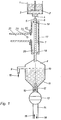
- a preferred embodiment of a device for the production of microspheres according to the invention has an essentially constant temperature of e.g. -5 ° C coolable storage vessel 1 for a mixed feed solution 2, which contains a motor-driven stirrer 3 and is equipped with a drop generator 4 on the bottom of a conventional type.
- a plastic tube 6 connects to the drop generator 4, e.g. made of polytetrafluoroethylene, which is arranged vertically and coaxially with the outlet opening 5 of the drop generator 4, so that mixed feed drops 7 emitted by the drop generator 4 can move freely through the plastic tube 6 without touching the wall.
- the plastic pipe 6 opens at the bottom in a collecting vessel 8, which has a lateral overflow 9 and whose conical bottom 11 merges into a pipe socket 12 which can be closed by a ball valve 13.
- the plastic tube 6 is arranged coaxially in a cavity resonator 17 and passed through the upper and lower end walls 18 and 19 thereof.
- a waveguide 21 is fastened to a side wall 20 of the cavity resonator 17 by means of a flange 22.
- the waveguide 21 contains at least one adjustment screw 23 and is connected via a e.g. mixed aperture 24 coupled to the cavity resonator 17, as is known from microwave technology.
- Cavity resonator 17 and waveguide 21 belong to a microwave device, for which a block diagram is shown in FIG. 2 and which will be described in more detail.
- the mixed feed drops 7 emitted by the drop generator 4 are heated in free fall on a vertical path by dielectric heating of microwaves standing in the radiation field from the X-band range to the gelling temperature.
- the mixed feed solution 2 located in the storage vessel 1 contains, in addition to the metal salt (s), the reaction substances required for solidification by internal gelation, such as hexamethylenetetramine and urea, and the drop generator 4 generates drops of substantially the same size from the mixed feed solution.
- microwave energy is stored in the cavity resonator 17 as a standing wave, the plastic tube 6 being arranged in the cavity resonator 17 in such a way that the mixed feed drops 7 falling through the plastic tube 6 traverse an area of a maximum electrical field component and absorb field energy through dielectric losses.
- This energy absorption causes a rapid temperature increase in the mixed feed drops 7, which leads to the triggering of the gelation.
- the gelation of the mixed feed drops 7 must have progressed so far in the microwave field that the gelled microspheres are no longer damaged in the subsequent treatment, i.e. that the falling distance in the microwave field must be sufficiently long and accordingly the cavity resonator 17 with the plastic tube 6 must be dimensioned accordingly.
- the plastic tube 6 delimits a relatively narrow treatment space for the mixed feed drops 7 in the interior of the cavity resonator 17, so that the same atmosphere as in the surroundings is present in the cavity resonator 17.
- This narrow treatment chamber which represents a flow channel, generally creates more favorable thermal conditions for a more uniform gelation of the mixed feed drops than the, by comparison, voluminous interior of the cavity resonator 17.
- the plastic tube 6 provides a particular advantage in the production of nuclear fuel microspheres, since at most that Plastic tube 6 is contaminated inside by radiating material, but not the cavity resonator 17th
- the collecting vessel 8 contains a washing liquid, e.g. an aqueous ammonia solution 10, into which the gelled microspheres 7 fall from the plastic tube 6, whereby - as already mentioned - the microspheres in the microwave field are already gelled to such an extent that they cannot be deformed by the ammonia solution when immersed in them .
- a washing liquid e.g. an aqueous ammonia solution 10
- the microspheres are fed continuously or cyclically to the washing column 14 by passing them through the dosing device, e.g. Cyclically actuated ball valve 13 are given in countercurrent to the ammonia solution of the washing column 14, as indicated in FIG. 1 by the arrows 15 for the direction of flow of the washing liquid and by the arrows 16 for the direction of movement of the microspheres.
- FIG. 2 A block diagram is shown in FIG. 2 for a preferred embodiment of the microwave device containing the cavity resonator 17.
- the microwave device works in the X-band, i.e. with wavelengths around 3 cm.
- a microwave generator 25 is provided with an output power in the mW range, which is of a conventional design and has an adjusting device 26 with which the frequency of the microwave generated within the X-band can be selected.
- a traveling wave tube 27 (TWT) is connected to the microwave generator 25 and amplifies the output power up to approximately 100 watts.
- the amplified microwave is fed into the cavity resonator 17 via a circulator 28 through the waveguide 21 containing the adjustment screw (s) 23 (FIG. 1) and sealed off with the mixed aperture 24.
- the circulator 28 prevents the wave reflected in the cavity resonator 17 from getting back into the traveling wave tube 27.
- the reflected wave is deflected into a load 30 and destroyed there by a side arm 29 of the circulator 28.
- the cavity resonator 17 is cuboid and dimensioned for the TE icx mode, where x has a value between 11 and 21.
- the cavity resonator 17 represents the consumer in the microwave device.
- a directional coupler 31 is connected to the waveguide 21 and is used to extract a small part of the reflected power.
- the extracted part of reflected power is led to a power meter 35 via a waveguide-to-coaxial transition 32 and two series-connected coaxial attenuators 33 and 34, one of which is variable.
- the frequency should be matched to the resonance frequency of the cavity resonator 17 containing the plastic tube 6 loaded with mixed feed drops 7.
- the microwave generator 25 is set to generate a microwave of a corresponding frequency.
- the frequency of the microwave generated is varied by means of the setting device 26 on the microwave generator 25 and the power meter 35 is observed.
- the measured reflected power has its minimum, and the microwave generator 25 then remains set to the corresponding frequency. This adjustment takes little time and is conveniently carried out during the usual test run.
- Such a cavity resonator has its own resonance frequency of 12.4 GHz in the TE 10 (11) mode, unloaded and without a plastic tube 6, and the wavelength in the cavity resonator is 2.85 cm.
- a tube 6 made of polytetrafluoroethylene (Teflon °) with an inner diameter of 8 mm and an outer diameter of 10 mm was inserted into the cavity. With such a plastic tube 6, the resonance frequency drops to 12.2 GHz and the quality factor is 30,000. If the plastic tube 6 is loaded with drops from an aqueous mixed feed solution, yet another, generally minor change in the resonance frequency occurs, and that Resonance frequency is about 12.19 GHz, for example, when water drips through.
- the drop distance in the microwave field that is decisive for the heating of the drops is therefore only about 15.6 cm. However, this relatively short distance is sufficient to heat free-falling mixed feed drops to a temperature which ensures gelation at the above-mentioned power of approximately 100 watts.
Landscapes
- Chemical & Material Sciences (AREA)
- Physics & Mathematics (AREA)
- Electromagnetism (AREA)
- Dispersion Chemistry (AREA)
- Organic Chemistry (AREA)
- Chemical Kinetics & Catalysis (AREA)
- Physical Or Chemical Processes And Apparatus (AREA)
- Manufacturing Of Micro-Capsules (AREA)
- Glanulating (AREA)
- Constitution Of High-Frequency Heating (AREA)
Applications Claiming Priority (2)
| Application Number | Priority Date | Filing Date | Title |
|---|---|---|---|
| DE3035845A DE3035845C2 (de) | 1980-09-23 | 1980-09-23 | Verfahren und Vorrichtung zur Herstellung von Mikrokugeln durch interne Gelierung von Mischfeed-Tropfen |
| DE3035845 | 1980-09-23 |
Publications (2)
| Publication Number | Publication Date |
|---|---|
| EP0048360A1 EP0048360A1 (de) | 1982-03-31 |
| EP0048360B1 true EP0048360B1 (de) | 1984-10-24 |
Family
ID=6112654
Family Applications (1)
| Application Number | Title | Priority Date | Filing Date |
|---|---|---|---|
| EP81106882A Expired EP0048360B1 (de) | 1980-09-23 | 1981-09-03 | Verfahren und Vorrichtung zur Herstellung von Mikrokugeln durch interne Gelierung von Mischfeed-Tropfen |
Country Status (5)
| Country | Link |
|---|---|
| US (1) | US4431164A (enExample) |
| EP (1) | EP0048360B1 (enExample) |
| JP (1) | JPS57119823A (enExample) |
| CA (1) | CA1156008A (enExample) |
| DE (1) | DE3035845C2 (enExample) |
Families Citing this family (28)
| Publication number | Priority date | Publication date | Assignee | Title |
|---|---|---|---|---|
| DE3142356A1 (de) * | 1981-10-26 | 1983-05-11 | Alkem Gmbh, 6450 Hanau | "verfahren zum endkonditionieren von radioaktivem und/oder toxischem abfall" |
| GB8614566D0 (en) * | 1986-06-16 | 1986-07-23 | Ici Plc | Spraying |
| DE3632396A1 (de) * | 1986-09-24 | 1988-03-31 | Hoechst Ag | Verfahren zur herstellung von metalloxiden oder metallmischoxiden |
| US4753675A (en) * | 1986-10-17 | 1988-06-28 | Ovonic Synthetic Materials, Inc. | Method of preparing a magnetic material |
| AU605236B2 (en) * | 1986-12-30 | 1991-01-10 | Hallsworth & Associates Pty. Limited | Improvements in or relating to the formation of metal alkoxides and metal powders by the use of microwave radiation |
| JP2777131B2 (ja) * | 1987-11-09 | 1998-07-16 | 旭精工株式会社 | 回転運動を直線運動に変換する機構 |
| DE4012197C2 (de) * | 1990-04-14 | 1994-08-18 | Heraeus Gmbh W C | Verfahren zur Herstellung teilchenförmigen Metalls und Vorrichtung zur Durchführung des Verfahrens |
| US5154899A (en) * | 1991-06-28 | 1992-10-13 | Sturcken Edward F | Metal recovery from porous materials |
| US5324485A (en) * | 1992-08-12 | 1994-06-28 | Martin Marietta Energy Systems, Inc. | Microwave applicator for in-drum processing of radioactive waste slurry |
| JP3462562B2 (ja) * | 1994-04-14 | 2003-11-05 | 日本原子力研究所 | ゲル粒子製造方法及び装置 |
| DE19602525A1 (de) * | 1996-01-25 | 1997-08-07 | Starck H C Gmbh Co Kg | Sphärische Keramikformkörper, Verfahren zu ihrer Herstellung sowie deren Verwendung |
| US5653775A (en) * | 1996-01-26 | 1997-08-05 | Minnesota Mining And Manufacturing Company | Microwave sintering of sol-gel derived abrasive grain |
| WO1998046210A1 (en) * | 1997-04-16 | 1998-10-22 | Katoot Mohammad W | Method and composition for targeted delivery of compounds |
| US6881482B2 (en) * | 2001-08-16 | 2005-04-19 | Southwest Research Institute | Microencapsulation using electromagnetic energy and core and shell materials with different dielectric constants and dissipation factors |
| DE20113222U1 (de) * | 2001-08-21 | 2001-11-15 | Truplast Kunststofftechnik GmbH, 35428 Langgöns | Schlauchleitung mit Muffe |
| JP4334316B2 (ja) * | 2003-10-16 | 2009-09-30 | 原子燃料工業株式会社 | 重ウラン酸アンモニウム粒子製造装置 |
| NL2000448C2 (nl) * | 2006-03-21 | 2010-09-13 | Sonder Food Systems B V | Inrichting voor het pasteuriseren van een massa voedingswaar. |
| CN102188932B (zh) * | 2011-01-20 | 2012-12-12 | 张志勤 | 连续形成球体的方法及用于该方法的成形装置 |
| JP6241842B2 (ja) * | 2013-08-30 | 2017-12-06 | 国立研究開発法人産業技術総合研究所 | 化学物質合成装置及び化学物質合成方法 |
| EP3287213A1 (en) * | 2016-08-23 | 2018-02-28 | Paul Scherrer Institut | Aqueous additive production method for the fabrication of ceramic and/or metallic bodies |
| CN209712260U (zh) | 2018-06-21 | 2019-12-03 | 革新(厦门)运动器材有限公司 | 一种折叠床架 |
| CN209712259U (zh) | 2018-06-21 | 2019-12-03 | 革新(厦门)运动器材有限公司 | 一种折叠床 |
| CN108618459A (zh) | 2018-06-21 | 2018-10-09 | 革新(厦门)运动器材有限公司 | 一种折叠床架 |
| CN210144265U (zh) | 2018-06-21 | 2020-03-17 | 革新(厦门)运动器材有限公司 | 一种折叠床架 |
| CN209315344U (zh) | 2018-06-21 | 2019-08-30 | 革新(厦门)运动器材有限公司 | 一种可折叠的床架 |
| CN108618458A (zh) | 2018-06-21 | 2018-10-09 | 革新(厦门)运动器材有限公司 | 一种折叠床架 |
| EP3895794A1 (en) * | 2020-04-15 | 2021-10-20 | HighFly Therapeutics (HK) Limited | Method and system of producing hydrogel microspheres |
| JP2022059529A (ja) * | 2020-10-01 | 2022-04-13 | マイクロ波化学株式会社 | マイクロ波処理装置、及びマイクロ波処理方法 |
Family Cites Families (10)
| Publication number | Priority date | Publication date | Assignee | Title |
|---|---|---|---|---|
| US3518328A (en) * | 1967-03-21 | 1970-06-30 | Grace W R & Co | Process for preparing microspheres of uranium,plutonium or thorium carbide |
| US3617584A (en) * | 1967-07-26 | 1971-11-02 | Grace W R & Co | Process for forming uniform microspheres |
| GB1407978A (en) * | 1971-09-29 | 1975-10-01 | Atomic Energy Authority Uk | Production of cermaic microspheres |
| US4184976A (en) * | 1973-05-08 | 1980-01-22 | Kernforschungsanlage Julich Gesellschaft Mit Beschrankter Haftung | Method of making metallic oxide or carbide particles |
| IT1051330B (it) * | 1974-12-16 | 1981-04-21 | Hobeg Hochtemperaturreaktor | Procedimento per la fabbricazione di particelle sferiche di combusti bile e fertilizzante nucleare |
| AT366845B (de) * | 1977-05-24 | 1982-05-10 | Oesterr Forsch Seibersdorf | Verfahren zur herstellung von sphaerischen kernbrennstoffteilchen |
| AT349402B (de) * | 1977-05-24 | 1979-04-10 | Oesterr Studien Atomenergie | Verfahren zur herstellung von festen teilchen |
| AT351474B (de) * | 1977-05-24 | 1979-07-25 | Oesterr Studien Atomenergie | Vorrichtung und verfahren zur herstellung fester teilchen |
| DE2753503B1 (de) * | 1977-12-01 | 1978-12-14 | Kernforschungsanlage Juelich | Verfahren und Vorrichtung zur Herstellung von untereinander gleichen kugelfoermigen Brenn- und/oder Brutstoffpartikeln |
| US4242220A (en) * | 1978-07-31 | 1980-12-30 | Gentaku Sato | Waste disposal method using microwaves |
-
1980
- 1980-09-23 DE DE3035845A patent/DE3035845C2/de not_active Expired
- 1980-12-18 US US06/217,741 patent/US4431164A/en not_active Expired - Fee Related
-
1981
- 1981-09-03 EP EP81106882A patent/EP0048360B1/de not_active Expired
- 1981-09-10 CA CA000385634A patent/CA1156008A/en not_active Expired
- 1981-09-18 JP JP56146472A patent/JPS57119823A/ja active Granted
Also Published As
| Publication number | Publication date |
|---|---|
| DE3035845C2 (de) | 1986-05-22 |
| EP0048360A1 (de) | 1982-03-31 |
| DE3035845A1 (de) | 1982-04-01 |
| CA1156008A (en) | 1983-11-01 |
| US4431164A (en) | 1984-02-14 |
| JPS57119823A (en) | 1982-07-26 |
| JPH0133215B2 (enExample) | 1989-07-12 |
Similar Documents
| Publication | Publication Date | Title |
|---|---|---|
| DE3035845C2 (de) | Verfahren und Vorrichtung zur Herstellung von Mikrokugeln durch interne Gelierung von Mischfeed-Tropfen | |
| DE2909858C2 (de) | Verfahren und Gerät zur Erzeugung von Oxydpulver für die Herstellung von Nuklearbrennstoffpellets | |
| DE19628952B4 (de) | Vorrichtung zur Erzeugung von Plasma | |
| DE3152314C2 (enExample) | ||
| DE69106956T2 (de) | Verfahren zur Herstellung eines Polyimids. | |
| WO1999042778A2 (de) | Verfahren und vorrichtung zum mikrowellensintern von kernbrennstoff | |
| EP0501285A1 (de) | Vorrichtung zum Auslösen und/oder Fördern chemischer und/oder physikalischer Druckreaktionen | |
| DE2837628A1 (de) | Vorrichtung und verfahren zum formen expandierter kunststoffe durch ultrahochfrequenzstrahlung | |
| DE2623977B2 (de) | Verfahren und Vorrichtung zur Herstellung von rieselfähigem, direkt verpressbarem Urandioxid-Pulver | |
| DE2601684A1 (de) | Verfahren zur herstellung von brenn- und brutstoff-partikeln | |
| DE2451253A1 (de) | Verfahren zum sintern keramischer erzeugnisse und vorrichtung zur durchfuehrung des verfahrens | |
| DE1769837B2 (de) | Verfahren zur erzeugung von mikrokugelfoermigen teilchen | |
| DE4114039C2 (enExample) | ||
| DE29504746U1 (de) | Vorrichtung zum Herstellen eines dreidimensionalen Objektes mittels Lasersintern | |
| DE69306214T2 (de) | Vorrichtung für kontinuierliche Denitrierung | |
| DE2822370A1 (de) | Vorrichtung zur herstellung fester teilchen | |
| DE69402699T2 (de) | Verfahren und anlage zur herstellung von festen giesslingen aus einem im wesentlichen reaktiven medium und ofen zur erwärmung eines im wesentlichen flüssigen mediums | |
| DE3208047C2 (de) | Vorrichtung zur Herstellung von Gelteilchen | |
| DE2037232B2 (de) | Verfahren zur Herstellung von oxidischen und karbidischen Kernbrenn - und Brutstoffpartikeln für Hochtemperatur-Reaktoren | |
| DE2451622C3 (de) | Verfahren und Vorrichtung zum Trocknen einer schwerschmelzbaren Auskleidung | |
| DE2627656A1 (de) | Vorrichtung zur behandlung von stoffen mit elektromagnetischer energie und verfahren zur herstellung der vorrichtung | |
| DE832026C (de) | Aus Hohlleitern aufgebaute Linse fuer elektromagnetische Wellen | |
| DE1598771A1 (de) | Geraet zur Messung und/oder Steuerung des Feuchtigkeitsgehalts von feinteiligem Material | |
| DE1540899C (de) | Infrarotstrahlungsheizvorrich tung mit flachenhaftem, hohlgewolb tem Strahler | |
| DE1951382A1 (de) | Verfahren zur Herstellung von Oxidgemischen |
Legal Events
| Date | Code | Title | Description |
|---|---|---|---|
| PUAI | Public reference made under article 153(3) epc to a published international application that has entered the european phase |
Free format text: ORIGINAL CODE: 0009012 |
|
| AK | Designated contracting states |
Designated state(s): BE CH FR GB IT NL |
|
| 17P | Request for examination filed |
Effective date: 19820918 |
|
| ITF | It: translation for a ep patent filed | ||
| GRAA | (expected) grant |
Free format text: ORIGINAL CODE: 0009210 |
|
| AK | Designated contracting states |
Designated state(s): BE CH FR GB IT LI NL |
|
| ET | Fr: translation filed | ||
| PLBE | No opposition filed within time limit |
Free format text: ORIGINAL CODE: 0009261 |
|
| STAA | Information on the status of an ep patent application or granted ep patent |
Free format text: STATUS: NO OPPOSITION FILED WITHIN TIME LIMIT |
|
| 26N | No opposition filed | ||
| ITTA | It: last paid annual fee | ||
| PGFP | Annual fee paid to national office [announced via postgrant information from national office to epo] |
Ref country code: CH Payment date: 19920925 Year of fee payment: 12 |
|
| PGFP | Annual fee paid to national office [announced via postgrant information from national office to epo] |
Ref country code: NL Payment date: 19920930 Year of fee payment: 12 |
|
| PGFP | Annual fee paid to national office [announced via postgrant information from national office to epo] |
Ref country code: BE Payment date: 19930727 Year of fee payment: 13 |
|
| PGFP | Annual fee paid to national office [announced via postgrant information from national office to epo] |
Ref country code: GB Payment date: 19930825 Year of fee payment: 13 |
|
| PG25 | Lapsed in a contracting state [announced via postgrant information from national office to epo] |
Ref country code: CH Effective date: 19930930 Ref country code: LI Effective date: 19930930 |
|
| REG | Reference to a national code |
Ref country code: GB Ref legal event code: 732E |
|
| PG25 | Lapsed in a contracting state [announced via postgrant information from national office to epo] |
Ref country code: NL Effective date: 19940401 |
|
| NLV4 | Nl: lapsed or anulled due to non-payment of the annual fee | ||
| REG | Reference to a national code |
Ref country code: CH Ref legal event code: PL |
|
| REG | Reference to a national code |
Ref country code: FR Ref legal event code: TP Ref country code: FR Ref legal event code: CA |
|
| PG25 | Lapsed in a contracting state [announced via postgrant information from national office to epo] |
Ref country code: GB Effective date: 19940903 |
|
| PG25 | Lapsed in a contracting state [announced via postgrant information from national office to epo] |
Ref country code: BE Effective date: 19940930 |
|
| BERE | Be: lapsed |
Owner name: PAUL SCHERRER INSTITUT Effective date: 19940930 |
|
| GBPC | Gb: european patent ceased through non-payment of renewal fee |
Effective date: 19940903 |
|
| PGFP | Annual fee paid to national office [announced via postgrant information from national office to epo] |
Ref country code: FR Payment date: 19980717 Year of fee payment: 18 |
|
| PG25 | Lapsed in a contracting state [announced via postgrant information from national office to epo] |
Ref country code: FR Free format text: LAPSE BECAUSE OF NON-PAYMENT OF DUE FEES Effective date: 20000531 |
|
| REG | Reference to a national code |
Ref country code: FR Ref legal event code: ST |