EP0045274B1 - Luftdichter Verschluss für Gefässe - Google Patents
Luftdichter Verschluss für Gefässe Download PDFInfo
- Publication number
- EP0045274B1 EP0045274B1 EP81710033A EP81710033A EP0045274B1 EP 0045274 B1 EP0045274 B1 EP 0045274B1 EP 81710033 A EP81710033 A EP 81710033A EP 81710033 A EP81710033 A EP 81710033A EP 0045274 B1 EP0045274 B1 EP 0045274B1
- Authority
- EP
- European Patent Office
- Prior art keywords
- ring
- membrane
- edge
- vessel
- diaphragm
- Prior art date
- Legal status (The legal status is an assumption and is not a legal conclusion. Google has not performed a legal analysis and makes no representation as to the accuracy of the status listed.)
- Expired
Links
- 239000000463 material Substances 0.000 claims description 3
- 229920003051 synthetic elastomer Polymers 0.000 claims description 2
- 239000005061 synthetic rubber Substances 0.000 claims description 2
- 239000012780 transparent material Substances 0.000 claims description 2
- 229920001971 elastomer Polymers 0.000 claims 1
- 230000009965 odorless effect Effects 0.000 claims 1
- 239000005060 rubber Substances 0.000 claims 1
- 239000012528 membrane Substances 0.000 description 38
- 238000004519 manufacturing process Methods 0.000 description 5
- 239000007795 chemical reaction product Substances 0.000 description 2
- 206010053648 Vascular occlusion Diseases 0.000 description 1
- 239000000853 adhesive Substances 0.000 description 1
- 230000001070 adhesive effect Effects 0.000 description 1
- 238000011161 development Methods 0.000 description 1
- 230000018109 developmental process Effects 0.000 description 1
- 238000006073 displacement reaction Methods 0.000 description 1
- 239000013013 elastic material Substances 0.000 description 1
- 238000001746 injection moulding Methods 0.000 description 1
- 230000014759 maintenance of location Effects 0.000 description 1
- 239000004033 plastic Substances 0.000 description 1
- 239000011148 porous material Substances 0.000 description 1
- 230000008092 positive effect Effects 0.000 description 1
- 230000002792 vascular Effects 0.000 description 1
- 208000021331 vascular occlusion disease Diseases 0.000 description 1
Images
Classifications
-
- B—PERFORMING OPERATIONS; TRANSPORTING
- B65—CONVEYING; PACKING; STORING; HANDLING THIN OR FILAMENTARY MATERIAL
- B65D—CONTAINERS FOR STORAGE OR TRANSPORT OF ARTICLES OR MATERIALS, e.g. BAGS, BARRELS, BOTTLES, BOXES, CANS, CARTONS, CRATES, DRUMS, JARS, TANKS, HOPPERS, FORWARDING CONTAINERS; ACCESSORIES, CLOSURES, OR FITTINGS THEREFOR; PACKAGING ELEMENTS; PACKAGES
- B65D51/00—Closures not otherwise provided for
- B65D51/14—Rigid discs or spherical members adapted to be held in sealing engagement with mouth of container, e.g. closure plates for preserving jars
-
- B—PERFORMING OPERATIONS; TRANSPORTING
- B65—CONVEYING; PACKING; STORING; HANDLING THIN OR FILAMENTARY MATERIAL
- B65D—CONTAINERS FOR STORAGE OR TRANSPORT OF ARTICLES OR MATERIALS, e.g. BAGS, BARRELS, BOTTLES, BOXES, CANS, CARTONS, CRATES, DRUMS, JARS, TANKS, HOPPERS, FORWARDING CONTAINERS; ACCESSORIES, CLOSURES, OR FITTINGS THEREFOR; PACKAGING ELEMENTS; PACKAGES
- B65D41/00—Caps, e.g. crown caps or crown seals, i.e. members having parts arranged for engagement with the external periphery of a neck or wall defining a pouring opening or discharge aperture; Protective cap-like covers for closure members, e.g. decorative covers of metal foil or paper
- B65D41/02—Caps or cap-like covers without lines of weakness, tearing strips, tags, or like opening or removal devices
- B65D41/22—Caps or cap-like covers with elastic parts adapted to be stretched over the container
Definitions
- the invention relates to an airtight vessel closure with a cover plate which can be placed on the edge of the opening to be closed and which projects beyond the edge and which has a rigid body which is made up of a membrane made of rubber-elastic material and can be placed on the opening edge and which has two mutually encompassing rings, between which the Edge of the membrane is clamped.
- US-A-3 901 405 also shows a vessel closure with two rings holding a membrane between them.
- this requires a lot of effort and still does not result in a reliable, permanent hold of the membrane.
- the positive engagement of the two rings provided according to the invention advantageously also results in a positive fit of the edge of the membrane clamped between the rings. This advantageously ensures that excellent retention of the membrane is ensured even with comparatively low clamping forces. For this reason, relatively large tolerances can therefore advantageously be permitted in the manufacture of the rings, which considerably simplifies and reduces the cost of manufacture.
- Another very special advantage of the measures according to the invention can be seen in the fact that the positive connection provided here also facilitates the exact assembly of the membrane. In this context, it can be assumed that the membrane is held or carried reliably even when the rings are brought together by the edges provided to achieve the positive connection, so that a reliable mutual engagement is achieved without any significant effort.
- the measures according to the invention accordingly result in both simple and inexpensive manufacture and simple and inexpensive assembly and nevertheless lead to a reliable hold of the membrane, which has a positive effect on the production costs and the quality of the end product. Since the end product in the present case is a mass-produced item, these improvements in terms of price and quality result in very great economic value overall.
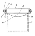
- FIG. 1 An exemplary embodiment of the invention shown schematically in the drawing is explained in more detail below with reference to the drawing.
- the drawing shows a radial section through a vascular occlusion according to the invention.
- the vessel closure shown in the drawing consists of an annular body 1, which is fanned out by a membrane 2.
- the ring body 1 is in two parts and consists of an inner support ring 3 and a clamping ring 4 encompassing this with mutual positive locking.
- the membrane 2 is here formed by a cutout from a material web and is clamped with its edge 5 between the support ring 3 and the clamping ring 4.
- the support ring 3 is provided here in the region of its end face, which is folded out by the membrane 2, with a radially outwardly directed edge offset 6, which is encompassed by the edge 5 of the membrane 2 and is engaged behind by the clamping ring 4 pressing against the edge 5 of the membrane 2. Due to the resulting positive connection, the clamp connection for holding the membrane 2 is relieved and the membrane 2 is secured in its position, so that a permanent hold of the membrane 2 is to be expected even under robust operating conditions.
- the support ring 1 is provided with a further radially outward bent portion 6, which is arranged here in the region of its end face opposite the membrane 2, which provides a reliable securing of the position of the clamping ring 4 formed here as a simple ring with a circular cross section.
- the support ring 3 and the clamping ring 4 can simply be designed as plastic injection moldings.
- the support ring 3 forms a dimensionally stable component.
- the clamping ring 4 can be designed as a resilient ring.
- the vessel closure shown is simply placed with the membrane 2 on the edge of the vessel 7 indicated by its outline. Subsequently, the membrane 2 is simply pushed slightly towards the interior of the vessel in the area of its area spanning the edge of the vessel, as indicated at 2a. Here, an amount of air corresponding to the curvature of the membrane 2 is displaced from the container contents. When the rubber-elastic membrane 2 springs back, a negative pressure is created in the vessel 7, which pulls the vascular closure firmly onto the edge of the vessel. The partial vacuum created as a result of air displacement also ensures that the contents of the container remain fresh for long periods and are excellently preserved.
- the membrane 2 consists of an odor-free, synthetic rubber. This material ensures excellent elasticity, so that a self-resilient resilience of the membrane 2 takes place and at the same time a full contact is ensured at the edge of the vessel to be closed, even if this edge should have slight unevenness, which, for. B. can occur with open cans by means of a can opener. In addition, complete freedom from pores is ensured, so that the partial vacuum generated in the container to be closed is maintained unchanged even over a long period of time. It is also ensured that such a membrane does not accept the smell of the container contents, nor does it give off its own odor to the latter. In the illustrated embodiment, the membrane 2 is made of transparent material, so that there is practically a viewing window and a control of the container content is possible.
- the membrane 2 is clamped between the support ring 3 and the clamping ring 4 only in the assembly position shown. But it would also be conceivable to firmly connect the membrane 2 to the clamping ring 4 by suitable means.
Landscapes
- Engineering & Computer Science (AREA)
- Mechanical Engineering (AREA)
- Closures For Containers (AREA)
Description
- Die Erfindung betrifft einen luftdichten Gefäßverschluß mit einer auf den Rand der zu verschließenden Öffnung auflegbaren, den Rand überragenden Abdeckscheibe, die einen von einer aus gummielastischem Material bestehenden, auf den Öffnungsrand auflegbaren Membrane ausgefachten Ririgkörper aufweist, der zwei einander umfassende Ringe besitzt, zwischen denen der Rand der Membrane eingespannt ist.
- Eine Anordnung dieser Art ist aus der CH-A 23 525 bekannt. Bei dieser bekannten Anordnung soll die Membrane ausschließlich kraftschlüssig zwischen den beiden Ringen des Ringkörpers gehalten werden. Die beiden, die Membrane zwischen sich einklemmenden Ringe besitzen nämlich glatte, einander zugewandte Ringflächen. Die Erfahrung hat jedoch gezeigt, daß mit Hilfe derartiger Ringe die Membrane nicht nur nicht sicher genug gehalten wird, sondern auch bei vernünftigem Herstellungs- und Montageaufwand nicht zuverlässig genug in eine definierte Stellung zwischen den beiden Ringen gebracht werden kann. Vielmehr besteht hierbei die Gefahr, daß sich der zwischen den Ringen eingeklemmte bzw. einzuklemmende Rand der Membrane bereits während der Montage der Ringe oder jedenfalls im Laufe längerer Betriebszeiten verschiebt, was zur Folge hat, daß eine definierte Stellung des Rands der Membrane nur sehr schwierig zu erreichen ist und die Membrane im Laufe längerer Betriebszeiten auf jeden Fall aus der durch die beiden Ringe gebildeten Halterung herausschlüpft.
- Die US-A 3 901 405 zeigt ebenfalls einen Gefäßverschluß mit zwei eine Membrane zwischen sich aufnehmenden Ringen. Hierbei handelt es sich jedoch um zwei aufeinander aufliegende Ringe, die sich nicht umfassen und die Membrane dementsprechend auch nicht zwischen siqh einspannen können, so daß hier eine Klebverbindung zur Halterung der Membrane unbedingt erforderlich ist. Dies erforder jedoch einen hohen Aufwand und ergibt dennoch keinen zuverlässigen, dauerhaften Halt der Membrane.
- Hiervon ausgehend ist es daher die Aufgabe der vorliegenden Erfindung, eine Anordnung gattungsgemäßer Art mit einfachen und kostengünstigen Mitteln so zu verbessern, daß bereits bei vergleichsweise geringen Klemmkräften ein zuverlässiger, dauerhafter Halt der Membrane gewährleistet ist.
- Diese Aufgabe wird erfindungsgemäß dadurch gelöst, daß die die Membrane zwischen sich einklemmenden Ringe formschlüssig aneinander festgelegt sind, wobei der radial innere Ring zumindest einen radial nach außen gerichteten, vom äußeren Ring hintergriffenen Wandvorsprung aufweist.
- Der erfindungsgemäß vorgesehene Formschluß der beiden Ringe ergibt in vorteilhafter Weise auch einen formschlüssigen Sitz des zwischen den Ringen eingespannten Rands der Membrane. Hierdurch ist in vorteilhafter Weise sichergestellt, daß bereits mit vergleichsweise geringen Klemmkräften ein ausgezeichneter Halt der Membrane gewährleistet wird. Aus diesem Grund können daher bei der Herstellung der Ringe in vorteilhafter Weise verhältnismäßig große Toleranzen zugelassen werden, was die Herstellung nicht unwesentlich vereinfacht und verbilligt. Ein weiterer ganz besonderer Vorteil der erfindungsgemäßen Maßnahmen ist jedoch darin zu sehen, daß der hier vorgeshene Formschluß auch die exakte Montage der Membrane erleichtert. In diesem Zusammenhang ist nämlich davon auszugehen, daß die Membrane durch die zur Erzielung des Formschlusses vorgesehenen Kanten auch bereits beim Zusammenführen der Ringe zuverlässig gehalten bzw. mitgenommen wird, so daß ohne nennenswerten Aufwand ein zuverlässiger gegenseitiger Eingriff erreicht wird. Die erfindungsgemäßen Maßnahmen ergeben demnach sowohl eine einfache und kostengünstige Herstellung als auch eine einfache und kostengünstige Montage und führen dennoch zu einem zuverlässigen Halt der Membrane, was sich positiv auf die Gestehungskosten und die Qualität des Endprodukts auswirkt. Da es sich beim Endprodukt im vorliegenden Fall um einen Massenartikel handelt, ergeben diese Verbesserungen hinsichtlich Preis und Qualität insgesamt einen sehr großen wirtschaftlichen Wert.
- Vorteilhafte Ausgestaltungen und zweckmäßige Weiterbildungen der übergeordneten Maßnahmen sind in den Ansprüchen 2 bis 5 gekennzeichnet.
- Nachstehend wird ein in der Zeichnung schematisch dargestelltes Ausführungsbeispiel der Erfindung anhand der Zeichnung näher erläutert. Die Zeichnung ziegt einen Radialschnitt durch einen erfindungsgemäßen Gefäßverschluß.
- Der in der Zeichnung dargestellte Gefäßverschluß besteht aus einem Ringkörper 1, der durch eine Membrane 2 ausgefacht ist. Der Ringkörper 1 ist zweiteilig und besteht aus einem inneren Stützring 3 und einem diesen unter gegenseitigem Formschluß umfassenden Spannring 4. Die Membrane 2 wird hierbei durch einen Ausschnitt aus einer Warenbahn gebildet und ist mit ihrem Rand 5 zwischen dem Stützring 3 und dem Spannring 4 eingeklemmt.
- Der Stützring 3 ist hier im Bereich seiner von der Membrane 2 ausgefachten Stirnseite mit einer nach radial außen gerichteten Randabkröpfung 6 versehen, die vom Rand 5 der Membrane 2 umfaßt und von dem den Rand 5 der-Membrane 2 anpressenden Spannring 4 hintergriffen wird. Durch den hierdurch bewirkten Formschluß werden die Klemmverbindung zur Halterung der Membrane 2 entlastet und die Membrane 2 in ihrer Lage gesichert, so daß auch bei robusten Betriebsverhältnissen ein dauerhafter Halt der Membrane 2 zu erwarten ist. Im dargestellten Ausführungsbeispiel ist der Stützring 1 mit einer weiteren, hier im Bereich seiner, der Membrane 2 gegenüberliegenden Stirnseite angeordneten, radial nach außen gerichteten Randabkröpfung 6 versehen, was eine zuverlässige Lagesicherung des hier als einfacher Ring mit kreisförmigem Querschitt ausgebildeten Spannrings 4 ergibt.
- Der Stützring 3 und der Spannring 4 können einfach als Kunststoff-Spritzgußformlinge ausgebildet sein. Der Stützring 3 bildet dabei ein formstabiles Bauteil. Der Spannring 4 kann als federnder Ring ausgebildet sein.
- Der dargestellte Gefäßverschluß wird einfach mit der Membrane 2 auf den Rand des durch seine Umrißlinien angedeuteten Gefäßes 7 aufgelegt. Anschließend wird die Membrane 2 einfach im Bereich ihres den Gefäßrand überspannenden Bereichs leicht zum Gefäßinnenraum hin durchgedrückt, wie bei 2a angedeutet ist. Hierbei wird eine der Wölbung der Membrane 2 entsprechende Luftmenge aus dem Behälterinhalt verdrängt. Beim Zurückfedern der gummielastischen Membrane 2 entsteht im Gefäß 7 ein Unterdruck, welcher den Gefäbßverschluß auf dem Gefäßrand festsaugt. Das infolge der Luftverdrängung erzeugte Teilvakuum stellt außerdem sicher, daß der Behälterinhalt über lange Zeiträume hinweg frisch bliebt und ausgezeichnet konserviert ist.
- Die Membrane 2 besteht aus einem geruchfreien, synthetischen Gummi. Dieses Material gewährleistet eine ausgezeichnete Elastizität, so daß eine selbstättige Rückfederung der Membrane 2 erfolgt und gleichzeitig auch eine satte Anlage am Rand des zu verschließenden Gefäßes gewährleitet ist, auch wenn dieser Rand leichte Unebenheiten aufweisen sollte, was z. B. bei mittels eines Dosenöffners geöffneten Büchsen vorkommen kann. Außerdem ist hierbei eine völlige Porenfreiheit sichergestellt, so daß das im zu verschließenden Behälter erzeugte Teilvakuum auch über einen langen Zeitraum hinweg unverändert aufrecht erhalten wird. Ferner ist sichergestellt, daß eine derartige Membrane weder den Geruch des Behälterinhalts annimmt, noch ihren Eigengeruch an diesen abgibt. Im dargestellten Ausführungsbeispiel soll die Membrane 2 aus durchsichtigem Material bestehen, so daß sich praktisch ein Sichtfenster ergibt und eine Kontrolle des Behälterinhalts möglich ist.
- Im dargestellten Ausführungsbeispiel ist die Membrane 2 nur in der dargestellten Montagestellung zwischen dem Stützring 3 und dem Spannring 4 eingespannt. Es wäre aber auch denkbar, die Membrane 2 mit dem Spannring 4 durch geeignete Mittel fest zu verbinden.
Claims (5)
Priority Applications (1)
| Application Number | Priority Date | Filing Date | Title |
|---|---|---|---|
| AT81710033T ATE19613T1 (de) | 1980-07-29 | 1981-07-24 | Luftdichter verschluss fuer gefaesse. |
Applications Claiming Priority (4)
| Application Number | Priority Date | Filing Date | Title |
|---|---|---|---|
| DE8020280U | 1980-07-29 | ||
| DE19808020280 DE8020280U1 (de) | 1980-07-29 | 1980-07-29 | Luftdichter Gefaessverschluss |
| DE19818111728 DE8111728U1 (de) | 1981-04-18 | 1981-04-18 | Luftdichter Gefaessverschluss |
| DE8111728U | 1981-04-18 |
Publications (2)
| Publication Number | Publication Date |
|---|---|
| EP0045274A1 EP0045274A1 (de) | 1982-02-03 |
| EP0045274B1 true EP0045274B1 (de) | 1986-05-07 |
Family
ID=25948697
Family Applications (1)
| Application Number | Title | Priority Date | Filing Date |
|---|---|---|---|
| EP81710033A Expired EP0045274B1 (de) | 1980-07-29 | 1981-07-24 | Luftdichter Verschluss für Gefässe |
Country Status (2)
| Country | Link |
|---|---|
| EP (1) | EP0045274B1 (de) |
| DE (1) | DE3174557D1 (de) |
Cited By (1)
| Publication number | Priority date | Publication date | Assignee | Title |
|---|---|---|---|---|
| US9023445B2 (en) | 2011-10-14 | 2015-05-05 | Kellogg North America Company | Composite containers for storing perishable products |
Families Citing this family (3)
| Publication number | Priority date | Publication date | Assignee | Title |
|---|---|---|---|---|
| US5271518A (en) * | 1992-07-24 | 1993-12-21 | Environ Products Inc. | Sump cover |
| GB2429200A (en) * | 2005-08-15 | 2007-02-21 | Peter George Morrison | A reusable cover for a vessel |
| US7594586B2 (en) * | 2006-08-05 | 2009-09-29 | Cai Edward Z | Vacuum generating device for sealing perishable products and method of use |
Family Cites Families (2)
| Publication number | Priority date | Publication date | Assignee | Title |
|---|---|---|---|---|
| CH23525A (de) * | 1900-12-29 | 1902-08-15 | Johann Kroog | Verschlußvorrichtung für vollständig mit Flüssigkeit gefüllte Flaschen und andere Gefäße |
| US3901405A (en) * | 1974-02-04 | 1975-08-26 | Robert B Norberg | Hermetic closure member |
-
1981
- 1981-07-24 DE DE8181710033T patent/DE3174557D1/de not_active Expired
- 1981-07-24 EP EP81710033A patent/EP0045274B1/de not_active Expired
Cited By (1)
| Publication number | Priority date | Publication date | Assignee | Title |
|---|---|---|---|---|
| US9023445B2 (en) | 2011-10-14 | 2015-05-05 | Kellogg North America Company | Composite containers for storing perishable products |
Also Published As
| Publication number | Publication date |
|---|---|
| EP0045274A1 (de) | 1982-02-03 |
| DE3174557D1 (en) | 1986-06-12 |
Similar Documents
| Publication | Publication Date | Title |
|---|---|---|
| DE10014582C2 (de) | Dampfdruck-Kochtopf | |
| DE69502280T2 (de) | Filtervorrichtung | |
| DE1486690A1 (de) | Behaelter zum Abgeben eines fluessigen oder pulverfoermigen Materials | |
| DE69814228T2 (de) | Vorrichtung zum Befestigen eines Fensters an der Tür einer Waschmaschine | |
| DE4119166C2 (de) | Filterelement für eine Filterpresse | |
| EP0045274B1 (de) | Luftdichter Verschluss für Gefässe | |
| EP0247288B1 (de) | Filterpresse | |
| CH665779A5 (de) | Filterplatte. | |
| DE1765986U (de) | Scheibenfoermige filterpatrone. | |
| DE2362509C2 (de) | Wasserdichtes Uhrgehäuse | |
| EP0070473B1 (de) | Membranfilterplatte für Filterpressen | |
| DE3837968C2 (de) | Filtereinsatz, der im Verlauf eines Kanals auswechselbar von einem Schacht aufgenommen wird | |
| DE2232664A1 (de) | Steuerventileinrichtung | |
| DE2029275B2 (de) | Vorrichtung zur Befestigung eines Bauteils, insbesondere zur Befestigung eines optischen Blocks in einer Ausnehmung einer Fahrzeugkarosseriewand | |
| DE3902546C2 (de) | Filter | |
| DE2129670C2 (de) | Vorrichtung zum Messen von niedrigen Drücken | |
| EP0410190A1 (de) | Vase | |
| DE3220584A1 (de) | Dichtelement fuer eine schraubverbindung | |
| DE3415713A1 (de) | Siebdruckmaschine mit einem beweglichen drucktisch | |
| DE2228605A1 (de) | Vorrichtung zum einspannen eines flaechenelementes in einem rahmen | |
| DE2907581A1 (de) | Membranabdichtung fuer pneumatische antriebe | |
| DE19959747C2 (de) | Schmutzsauger mit elastischer Dichtung zwischen zwei Bauteilen | |
| DE3909687C2 (de) | ||
| DE1175397B (de) | Befestigungsvorrichtung fuer das Papierfilter in einem Staubsauger | |
| DE2947155C2 (de) | Filterplatte für Plattenfilterpressen |
Legal Events
| Date | Code | Title | Description |
|---|---|---|---|
| PUAI | Public reference made under article 153(3) epc to a published international application that has entered the european phase |
Free format text: ORIGINAL CODE: 0009012 |
|
| AK | Designated contracting states |
Designated state(s): AT CH DE FR IT |
|
| RBV | Designated contracting states (corrected) |
Designated state(s): AT CH DE FR IT LI |
|
| 17P | Request for examination filed |
Effective date: 19820729 |
|
| GRAA | (expected) grant |
Free format text: ORIGINAL CODE: 0009210 |
|
| AK | Designated contracting states |
Kind code of ref document: B1 Designated state(s): AT CH DE FR IT LI |
|
| PG25 | Lapsed in a contracting state [announced via postgrant information from national office to epo] |
Ref country code: IT Free format text: LAPSE BECAUSE OF FAILURE TO SUBMIT A TRANSLATION OF THE DESCRIPTION OR TO PAY THE FEE WITHIN THE PRESCRIBED TIME-LIMIT;WARNING: LAPSES OF ITALIAN PATENTS WITH EFFECTIVE DATE BEFORE 2007 MAY HAVE OCCURRED AT ANY TIME BEFORE 2007. THE CORRECT EFFECTIVE DATE MAY BE DIFFERENT FROM THE ONE RECORDED. Effective date: 19860507 Ref country code: FR Free format text: THE PATENT HAS BEEN ANNULLED BY A DECISION OF A NATIONAL AUTHORITY Effective date: 19860507 |
|
| REF | Corresponds to: |
Ref document number: 19613 Country of ref document: AT Date of ref document: 19860515 Kind code of ref document: T |
|
| REF | Corresponds to: |
Ref document number: 3174557 Country of ref document: DE Date of ref document: 19860612 |
|
| PG25 | Lapsed in a contracting state [announced via postgrant information from national office to epo] |
Ref country code: AT Effective date: 19860724 |
|
| PG25 | Lapsed in a contracting state [announced via postgrant information from national office to epo] |
Ref country code: LI Effective date: 19860731 Ref country code: CH Effective date: 19860731 |
|
| EN | Fr: translation not filed | ||
| PLBE | No opposition filed within time limit |
Free format text: ORIGINAL CODE: 0009261 |
|
| STAA | Information on the status of an ep patent application or granted ep patent |
Free format text: STATUS: NO OPPOSITION FILED WITHIN TIME LIMIT |
|
| REG | Reference to a national code |
Ref country code: CH Ref legal event code: PL |
|
| PG25 | Lapsed in a contracting state [announced via postgrant information from national office to epo] |
Ref country code: DE Effective date: 19870401 |
|
| 26N | No opposition filed |