EP0043078A2 - Method and apparatus for lifting or sinking buildings or parts thereof by using hydraulic-jack units which can be individually steered or grouped - Google Patents
Method and apparatus for lifting or sinking buildings or parts thereof by using hydraulic-jack units which can be individually steered or grouped Download PDFInfo
- Publication number
- EP0043078A2 EP0043078A2 EP81104832A EP81104832A EP0043078A2 EP 0043078 A2 EP0043078 A2 EP 0043078A2 EP 81104832 A EP81104832 A EP 81104832A EP 81104832 A EP81104832 A EP 81104832A EP 0043078 A2 EP0043078 A2 EP 0043078A2
- Authority
- EP
- European Patent Office
- Prior art keywords
- cylinder
- piston units
- building
- controllers
- central controller
- Prior art date
- Legal status (The legal status is an assumption and is not a legal conclusion. Google has not performed a legal analysis and makes no representation as to the accuracy of the status listed.)
- Granted
Links
Images


Classifications
-
- E—FIXED CONSTRUCTIONS
- E04—BUILDING
- E04G—SCAFFOLDING; FORMS; SHUTTERING; BUILDING IMPLEMENTS OR AIDS, OR THEIR USE; HANDLING BUILDING MATERIALS ON THE SITE; REPAIRING, BREAKING-UP OR OTHER WORK ON EXISTING BUILDINGS
- E04G23/00—Working measures on existing buildings
- E04G23/06—Separating, lifting, removing of buildings; Making a new sub-structure
-
- E—FIXED CONSTRUCTIONS
- E02—HYDRAULIC ENGINEERING; FOUNDATIONS; SOIL SHIFTING
- E02D—FOUNDATIONS; EXCAVATIONS; EMBANKMENTS; UNDERGROUND OR UNDERWATER STRUCTURES
- E02D35/00—Straightening, lifting, or lowering of foundation structures or of constructions erected on foundations
-
- E—FIXED CONSTRUCTIONS
- E04—BUILDING
- E04G—SCAFFOLDING; FORMS; SHUTTERING; BUILDING IMPLEMENTS OR AIDS, OR THEIR USE; HANDLING BUILDING MATERIALS ON THE SITE; REPAIRING, BREAKING-UP OR OTHER WORK ON EXISTING BUILDINGS
- E04G23/00—Working measures on existing buildings
- E04G23/06—Separating, lifting, removing of buildings; Making a new sub-structure
- E04G23/065—Lifting of buildings
Abstract
Description
In Senkungsgebieten, wie z.B. in Bergbaugebieten, treten oftmals Schieflagen an Gebäuden auf, die zur Vermeidung größerer Schäden möglichst frühzeitig zu beseitigen sind, dJh. die Gebäude müssen wieder in die Horizontale oder zumindestens annähernd in die horizontale Lage gebracht werden. Die möglichen Lagen der Hubebenen befinden sich unter den Fundamenten, in der Kellerwand über der Kellersohle oder unter der Kellerdecke.In subsidence areas, such as in mining areas often occur imbalances to buildings on the greater to avoid damage is to eliminate as early as possible, d J h. the buildings must be brought back into the horizontal or at least approximately in the horizontal position. The possible positions of the lifting levels are located under the foundations, in the basement wall above the basement floor or under the basement ceiling.
Zu diesem Zwecke ist es bekannt, eine Hilfskonstruktion aus Stahlträgern unter der Kellerdecke im Bereich neben allen tragenden Wänden einzubringen, welche nur für die Zwecke der Beseitigung der Schieflage, also für das Heben, Verwendung findet. Über diese Stahlkonstruktion müssen alle Gebäudelasten abgefangen und zur Begrenzung des Aufwandes auf möglichst wenige Hubpunkte konzentriert werden, an denen hydraulische Zylinder-Kolben-Einheiten angesetzt werden. Die hydraulischen Zylinder-Kolben-Einh&iten sind auf besonders dafür zu errichtende Fundamente aufgesetzt. Der Nachteil dieses bekannten Verfahrens besteht darin, daß dieses vergleichsweise aufwendig ist, weil sich der Einbau der Trägerkonstruktion und der für die hydraulischen.Zylinder-Kolben-Einheiten benötigten Fundamente oftmals sehr schwierig gestaltet. So ist es z.B. möglich, daß zur Beschaffung des notwendigen Raumes Wände ganz oder teilweise abgebrochen'.werden müßten, um die Träger und Fundamente überhaupt in das Kellergeschoß einbringen und anordnen zu können. Ein weiterer Nachteil besteht darin, daß die Steuerung der hydraulischen Zylinder-Kolben-Einheiten von Hand erfolgt. Es sind lediglich mechanische Hilfsmittel vorgesehen, z.B. in Form von Hubbegrenzern, welche derart geschaltet sind, daß bei Erreichen des Endanschlages an einer Zylinder-Kolben-Einheit über den Endanschlag die Abschaltung der anderen Zylinder-Kolben-Einheiten erfolgt. Die Steuerung der Zylinder-Kolben-Einheiten erfolgt einzeln oder zusammengefaßt in Gruppen, und zwar abhängig von der optischen Beobachtung einer Bedienungsperson. Aus dieser Art der Steuerung ergibt sich die Gefahr einer Rißbildung im oberen Gebäude, da die Steuerungsmöglichkeit nur sehr grob ist. Außerdem ist die Anzahl der Hubpunkte begrenzt. Eine größere Anzahl wäre zwar grundsätzlich möglich, jedoch ist diese wiederum nicht überschaubar. Diese beschränkte Überwachungsmöglichkeit bringt die Gefahr mit sich, daß das anzuhebende Gebäude bzw. der anzuhebende Gebäudeteil infolge unterschiedlicher Hubwege an benachbarten Zylinder-Kolben-Einheiten reißt, was wiederum mit erheblichen Folgekosten verbunden ist, um die aufgetretenen Risse zu beseitigen.For this purpose, it is known to introduce an auxiliary structure made of steel girders under the basement ceiling in the area next to all load-bearing walls, which is only used for the purpose of removing the skew, that is to say for lifting. All building loads must be absorbed via this steel structure and concentrated to limit the effort to as few lifting points as possible, at which hydraulic cylinder-piston units are attached. The hydraulic cylinder-piston units are placed on foundations that are specially designed for this purpose. The disadvantage of this known method is that it is comparatively complex because the installation of the support structure and the fun required for the hydraulic. Cylinder-piston units often very difficult. Thus it is possible for example, that canceled the procurement of the necessary space walls completely or partially would .werden 'to bringing about the support and foundation at all in the basement and arrange. Another disadvantage is that the hydraulic cylinder-piston units are controlled by hand. Only mechanical aids are provided, for example in the form of stroke limiters, which are switched in such a way that when the end stop on a cylinder-piston unit is reached, the other cylinder-piston units are switched off via the end stop. The cylinder-piston units are controlled individually or in groups, depending on the visual observation of an operator. This type of control creates the risk of cracking in the upper building, since the control option is only very rough. The number of lifting points is also limited. A larger number would be possible in principle, but again this is not manageable. This limited monitoring possibility entails the risk that the building to be lifted or the part of the building to be torn as a result of different stroke distances on adjacent cylinder-piston units, which in turn is associated with considerable consequential costs in order to eliminate the cracks that have occurred.
Von diesem Stand der Technik ausgehend liegt der Erfindung die Aufgabe zugrunde, ein Verfahren und eine Vorrichtung der eingangs genannten Art zu schaffen, welche unter Vermeidung vorerwähnter Nachteile die Beseitigung von Schieflagen von Gebäuden bzw. Gebäudeteilen in völlig selbsttätiger Weise ermöglicht, um optimale Bedingungen sowohl hinsichtlich der von den Zylinder-Kolben-Einheiten zurückzulegenden Wege und damit Begrenzung der zusätzlichen Spannungen im Baukörper als auch daraus resultierend die Vermeidung von Rißbildungen während-des Hebens des Gebäudes zu erreichen..Starting from this prior art, the invention has for its object to provide a method and an apparatus of the type mentioned which, while avoiding the aforementioned disadvantages, enables the removal of imbalances in buildings or parts of buildings in a completely automatic manner, in order to achieve optimal conditions both in terms of of the distances to be covered by the cylinder-piston units and thus limitation of the additional tensions in the structure and, as a result, the avoidance of cracks during the lifting of the building.
Gemäß der Erfindung wird dies verfahrensgemäß dadurch erreicht, daß die Schiefstellung des Gebäudes bzw. -teils als Ist-Wert ausgemessen und einem Zentralregler zugeführt wird, welcher durch Vergleich dieses Ist-Wertes mit den Abmessungen des Gebäudes bzw. -teils sowie den Positionen der Zylinder-Koiben-Einheiten und/oder Gruppen derselben im Gebäude bzw. -teil Soll-Werte bildet, welche auf an den Zylinder-Kolben-Einheiten vorgesehene Regler gegeben werden und die von den Zylinder-Kolben-Einheiten aufgrund der von ihrem zugehörigen Reglern gebildeten Stellsignale zurückgelegten Wege als Ist-Werte gemessen und in ihren Reglern fortlaufend zur Bildung von Stellsignalen für die Zylinder-Kolben-Einheiten mit den vom Zentralregler vorgegebenen Soll-Werten verglichen werden. Durch diese Regelung ist es möglich, völlig unabhängig von der Beobachtung durch Bedienungspersonen die Schieflage eines Gebäudeteils oder eines ganzen Gebäudes laufend zu korrigieren, bis die angestrebte horizontale Lage oder eine nahezu horizontale Lage erreicht ist. Es bedarf lediglich zu Beginn der Ermittlung des Ist-Wertes der Schieflage eines Ge- bäudes, was beispielsweise auf optischem Wege erfolgen kann, woraufhin durch einen Vergleich dieses Ist-Wertes mit den Abmes- sungen des Gebäudes und den Positionen der Zylinder-Kolben-Einheiten vom Zentralregler Soll-Werte für die einzelnen Zylinder-Kolben-Einheiten gebildet werden, die von deren Reglern weiter zu Stellsignalen für die Zylinder-Kolben-Einheiten verarbeitet werden, so daß diese entsprechend ihrer'Position im anzuhebenden Gebäude einen mehr oder weniger großen Weg zurücklegen, welcher ständig gemessen und als Regelgröße in die Regler der Zylinder-Kolben-Einheiten zurückgegeben werden, in denen wiederum die sich aus der Änderung der Ist-Lage des Gebäudes ergebenden neuen Werte als Soll-Werte-vorgegeben werden und so eine fortlaufende Regelung erfolgt, bis das Gebäude die gewünschte Lage erreicht hat. Die Abweichung der Hubwege einzelner Heber von den Soll-Werten wird vorzugsweise auf 0,5 mm begrenzt.According to the invention, this is achieved according to the method in that the skew of the building or part is measured as the actual value and is fed to a central controller which compares this actual value with the dimensions of the building or part and the positions of the cylinders -Coil units and / or groups of them in the building or part forms target values which are given to controllers provided on the cylinder-piston units and the cylinder-piston units on the basis of the control signals formed by their associated controllers The distances traveled are measured as actual values and their controllers are continuously compared with the target values specified by the central controller to form actuating signals for the cylinder-piston units. This regulation makes it possible completely independent of the observation by the operators Sch fla g e part of a building or an entire building ie to correct continuously, until the desired horizontal position or a nearly horizontal position reached. It requires only the beginning of the determination of the actual value of the imbalance of overall b ä ud what can be done by optical means, for example, then this by comparing the actual value m with the ex es- solutions of the building and the positions of the Cylinder-piston units are formed by the central controller setpoints for the individual cylinder-piston units, which are further processed by their controllers into control signals for the cylinder-piston units, so that these one more according to their position in the building to be lifted or less great distance, which is constantly measured and returned as a control variable in the controller of the cylinder-piston units, in which in turn the new values resulting from the change in the actual position of the building are specified as target values and so on Continuous regulation takes place until the building has reached the desired location. The deviation of the stroke lengths of individual jacks from the target values is preferably limited to 0.5 mm.
Vorteilhaft findet als Zentralregler ein Rechner, vorzugsweise ein Microprozessor, Verwendung.A computer, preferably a microprocessor, is advantageously used as the central controller.
Nach einem weiteren Merkmal der Erfindung sind die Regler der Zylinder-Kolben-Einheiten über eine serielle Schnittstelle mit dem Zentralregler verbunden, so daß vom Zentralregler aus je nach der Position der einzelnen Zylinder-Kolben-Einheiten ein mehr oder weniger großer Hub durchgeführt werden kann.According to a further feature of the invention, the controllers are Cylinder-piston units connected to the central controller via a serial interface, so that a more or less large stroke can be carried out from the central controller depending on the position of the individual cylinder-piston units.
Die aufgrund der von den Zylinder-Kolben-Einheiten zurückgelegten Wege gemessenen Ist-Werte werden von den Reglern der Zylinder-Kolben-Einheiten auf den Zentralregler gegeben und in diesem mit den vorgegebenen Hubwerten verglichen. Durch diese Rückmeldung ist es möglich festzustellen, ob der den einzelnen Zylinder-Kolben-Einheiten vorgegebene Hub auch tatsächlich zurückgelegt worden ist.'Sollte dieses nicht der Fall sein, d.h. also die Quittungssignale nicht beim Zentralregler ankommen, wird der Hebevorgang abgebrochen, da dann eine Störung vorliegen muß.The actual values measured on the basis of the distances covered by the cylinder-piston units are transferred from the controllers of the cylinder-piston units to the central controller and are compared in this with the specified stroke values. This feedback makes it possible to determine whether the stroke specified for the individual cylinder-piston units has actually been covered. ' If this is not the case, ie if the acknowledgment signals do not arrive at the central controller, the lifting process is interrupted because a fault must then exist.
Die Erfindung erstreckt sich weiterhin auf eine Vorrichtung der eingangs genannten Art, insbesondere zur Durchführung des vorgeschlagenen Verfahrens, bei welcher die hydraulischen Zylinder-Kolben-Einheiten in den der Lastableitung dienenden tragenden Bauteilen, wie z.B. Wände, Scheiben, Stützen usw., vorgesehen sind.The invention further extends to a device of the type mentioned at the outset, in particular for carrying out the proposed method, in which the hydraulic cylinder-piston units in the load-bearing components, such as e.g. Walls, panes, supports, etc. are provided.
Vorteilhaft sind die Zylinder-Kolben-Einheiten jeweils mit einer Pumpe, einem Hydraulikbehälter sowie Steuerventilen ausgerüstet. Durch diese Ausgestaltung ergibt sich eine außer- ordentlich kompakte Bauweise der einzelnen Zylinder-Kolben-Einheiten, welche eine schnelle und einfache Montage ermöglichen, da lediglich ein 220 V-Stromanschluß zu den einzelnen Zylinder-Kolben-Einheiten für deren Miniaturpumpe verlegt zu. werden braucht. Die Zylinder-Kolben-Einheiten werden in Ausnehmungen der tragenden Bauteile, z.B. unter der Kellerdecke des zu hebenden Gebäudes, eingesetzt, in einem so engen Abstand voneinander, daß es der Einbringung einer besonderen Trägerkonstruktion und der Vorsehung von Fundamenten für die Zylinder-Kolben-Einheiten nicht bedarf, da die tragenden Bauteile sowohl oberhalb als auch unterhalb der gewählten Hubebene ihre Funktionen behalten. Jede einzelne Zylinäer-Kolben-Einheit ist vorteilhaft mit einem Weggeber ausgerüstet, so daß ein in sich geschlossener Regelkreis vorliegt.The cylinder-piston units are each advantageously equipped with a pump, a hydraulic tank and control valves. This configuration results in an outside o rdentlich compact design of the individual cylinder-piston units, which allow quick and easy installation, since only a 220 V power connection to the individual cylinder piston units for their miniature pump relocated to. are needed. The cylinder-piston units are used in recesses of the load-bearing components, e.g. under the basement of the building to be lifted, at such a close distance from each other that it requires the introduction of a special support structure and the provision of foundations for the cylinder-piston units not required, since the load-bearing components retain their functions both above and below the selected lifting level. Each individual cylinder-piston unit is advantageously equipped with a displacement sensor, so that a closed control loop is present.
Ein Ausführungsbeispiel der Erfindung ist an Hand der Zeichnung näher erläutert, und zwar zeigt:
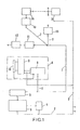
- Figur 1 ein Blockschaltbild des Regelkreises,
Figur 2 in schematischer Darstellung die Ansicht und Draufsicht einer Zylinder-Kolben-Einheit undFigur 3 in schematischer Darstellung die Anordnung einer Zylinder-Kolben-Einheit in einem tragenden Bauteil eines Gebäudes.
- FIG. 1 shows a block diagram of the control loop,
- Figure 2 is a schematic representation of the view and top view of a cylinder-piston unit and
- Figure 3 shows a schematic representation of the arrangement of a cylinder-piston unit in a load-bearing component of a building.
Wie aus dem Blockschaltbild der Figur 1 hervorgeht, ist mit 1 der elektrische Anschluß an das übliche 220 V-Netz bezeichnet. An die zu diesem Anschluß führenden Leitungen 2 ist der Zentralregler 3 angeschlossen, welcher von einem Tischrechner mit Terminal gebildet ist. Die vom Zentralregler 3 errechneten Werte können über den Drucker 4 zum Ausdruck gebracht werden. Die vom Zentralregler 3 ermittelten Werte werden über die serielle Schnittstelle 5 über die vieradrige BUS-Leitung 7 auf den Regler 8 der Zylinder-Kolben-Einheit 9 gegeben, die außerdem mit einem Weggeber 10 verbunden ist. Wie aus Figur 1 hervorgeht, sind Regler 8, Zylinder-Kolben-Einheit 9 sowie Weggeber 10 zu einer Einheit zusammengefaßt, wie durch 6 angedeutet ist. Diese Einheit 6 stellt einen in sich geschlossenen Regelkreis dar. sindAs can be seen from the block diagram in FIG. 1, 1 denotes the electrical connection to the usual 220 V network. The
Die weiteren Regler 11, 12, 13, 14, 15-n über Stern- und Ringleitungen 7 an das 220 V-Netz angeschlossen. Die Anzahl der Regler 8, 11-n und damit der zugehörigen Zylinder-Kolben-Einheiten 9 ist beliebig und richtet sich nach den Gegebenheiten des jeweiligen Bauwerkes.The
Die Wirkungsweise der Anordnung ist wie folgt:
- In dem Zentralregler 1 wird die z.B. auf optischem Wege gemessene Schieflage eines Gebäudes eingegeben, ebenso die Positionen der einzelnen Zylinder-Kolben-Einheiten 8 im Gebäude. Aus der Schieflage und den Positionen der Zylinder-Kolben-
Einheit 9 errechnet derZentralregler 3 in Abhängigkeit von einer vorgegebenen Höhe, um die das Gebäude schrittweise angehoben werden soll, beispielsweise um 3 cm, den jeweiligen Anhubweg der einzelnen Zylinder-Kolben-Einheiten 9. Diese Soll-Werte werden den Reglern.8, 11-n der einzelnen Zylinder-Kolben-Einheiten 9 vorgegeben, so daß der Anhebevorgang praktisch gleichzeitig erfolgt, wenn auch über diegemeinsamen Leitungen 7 der einzelnen Zylinder-Kolben-Einheiten zeitlich versetzt beaufschlagt werden. Die Zeitdifferenz ist jedoch so gering, daß diese in der Praxis vernachlässigbar ist, d.h. die einzelnen Zylinder-Kolben-Einheiten 9 beginnen nahezu gleichzeitig ihren Hubvorgang.
- In the central controller 1, the skew of a building, measured optically, for example, is entered, as are the positions of the individual cylinder-piston units 8 in the building. The
central controller 3 calculates the respective lifting path of the individual cylinder-piston units 9 from the skew and the positions of the cylinder-piston unit 9, depending on a predetermined height by which the building is to be gradually raised, for example by 3 cm. These setpoints are given to the controllers 8, 11-n of the individual cylinder-piston units 9, so that the lifting process takes place practically simultaneously, even though thecommon lines 7 of the individual cylinder-piston units are applied at different times. However, the time difference is so small that it is negligible in practice, ie the individual cylinder-piston units 9 begin their lifting process almost simultaneously.
Der Zentralregler 3 übermittelt über die serielle Schnittstelle 5 in Form eines parallelen seriellen Umsetzers mit Potentialtrennung die Sollvorgaben für die einzelnen Zylinder-Kolben-Einheiten 9 an deren Regler 8, 11-n. Da diese mit einem Weggeber 10 gekoppelt sind, findet eine Rückmeldung auf die zugehörigen Regler 8, 11-n statt und von diesen auch auf den Zentralregler 3, so daß in diesem ein Vergleich stattfinden kann, ob der vorgegebene Hubweg auch tatsächlich zurückgelegt worden ist. Wenn die Quittungssignale von den einzelnen Reglern 8, 11-n nicht beim Zentralregler 3 ankommen, wird der Hebevorgang abgebrochen, da dann eine Störung vorliegen muß.The
Es können beliebig viele Zylinder-Kolben-Einheiten angeschlossen werden, und zwar gruppenweise oder einzeln, wobei diese auch in Hintereinander- oder Parallelschaltung angeordnet sein können.Any number of cylinder-piston units can be connected, in groups or individually, which can also be arranged in series or in parallel.
Jede Einheit 6 stellt einen in sich geschlossenen Regelkreis dar, wobei zusätzlich eine Hin- und Rückleitung zu dem Zentralregler 3 besteht. Dessen Werte können auf einem Bildschirm sichtbar gemacht und über einen gesonderten Drucker 4 ausgedruckt werden.Each unit 6 represents a self-contained control loop, with an additional forward and return line to the
Wie aus Figur 2 ersichtlich, ist an jede Zylinder-Kolben-Einheit 9 eine Elektrokleinpumpe 16 angeschlossen, deren Vor- und Rücklaufleitungen 17 über Elektro-Magnetventile von dem zugehörigen Rechner 8 gesteuert sind. An der Zylinder-Kolben-Einheit 9 ist der Weggeber 10 angebracht, der elektrisch mit dem zugehörigen Regler 8 in Verbindung steht.As can be seen from FIG. 2, a small
Aus Figur 3 ist die Anordnung einer Zylinder-Kolben-Einheit 8 in der Nische 18 einer Innenwand eines Kellers ersichtlich, und zwar wird diese nach oben und unten durch Stahlplatten 19 abgedeckt. Die obere Stahlplatte 19 liegt plan unterhalb der Kellerdecke 20 an, während die untere Steuerplatte 19 auf einen Betonstein 21 aufgelegt ist, welcher in die Nische 18 eingesetzt ist.The arrangement of a cylinder-piston unit 8 in the
Claims (8)
Priority Applications (1)
| Application Number | Priority Date | Filing Date | Title |
|---|---|---|---|
| AT81104832T ATE18584T1 (en) | 1980-06-26 | 1981-06-23 | METHOD AND APPARATUS FOR LIFTING AND/OR LOWERING BUILDINGS OR PARTS USING HYDRAULIC CYLINDER-PISTONS UNITS CONTROLLABLE INDIVIDUALLY AND/OR IN GROUPS. |
Applications Claiming Priority (2)
| Application Number | Priority Date | Filing Date | Title |
|---|---|---|---|
| DE3023892 | 1980-06-26 | ||
| DE19803023892 DE3023892A1 (en) | 1980-06-26 | 1980-06-26 | METHOD AND DEVICE FOR LIFTING AND / OR LOWERING BUILDINGS OR PARTS, USING HYDRAULIC CYLINDER-PISTON UNITS WHICH ARE INDIVIDUALLY AND / OR GROUP-WIDE CONTROLLABLE |
Publications (3)
| Publication Number | Publication Date |
|---|---|
| EP0043078A2 true EP0043078A2 (en) | 1982-01-06 |
| EP0043078A3 EP0043078A3 (en) | 1982-06-23 |
| EP0043078B1 EP0043078B1 (en) | 1986-03-12 |
Family
ID=6105488
Family Applications (1)
| Application Number | Title | Priority Date | Filing Date |
|---|---|---|---|
| EP81104832A Expired EP0043078B1 (en) | 1980-06-26 | 1981-06-23 | Method and apparatus for lifting or sinking buildings or parts thereof by using hydraulic-jack units which can be individually steered or grouped |
Country Status (3)
| Country | Link |
|---|---|
| EP (1) | EP0043078B1 (en) |
| AT (1) | ATE18584T1 (en) |
| DE (1) | DE3023892A1 (en) |
Cited By (7)
| Publication number | Priority date | Publication date | Assignee | Title |
|---|---|---|---|---|
| FR2547291A1 (en) * | 1983-06-10 | 1984-12-14 | Epitoegepgyarto Vallalat | Electrohydraulic hoist for pre-fabricated building panels |
| EP0404971A1 (en) * | 1989-06-26 | 1991-01-02 | Bernfried Dr.-Ing. Sudbrack | Method and device for lifting, sinking and/or straightening a building |
| EP0457973A1 (en) * | 1990-05-25 | 1991-11-27 | GERB Gesellschaft für Isolierung mbH & Co. KG | Method for measuring the elevation and/or the subsidence of a building and measuring devices for applying the method |
| ES2067348A2 (en) * | 1991-12-04 | 1995-03-16 | Busquets Albert Busquets | Integral system for strengthening deteriorated beams and floor structures in buildings, accessories therefor and method of application |
| FR2823521A1 (en) * | 2001-04-13 | 2002-10-18 | Bouygues Batiment | Load support prop for formwork has driving means for raising and regulating descent of slide |
| RU2575193C1 (en) * | 2014-12-29 | 2016-02-20 | Николай Васильевич Мальцев | Method to level building, structure |
| RU2710741C1 (en) * | 2019-04-26 | 2020-01-10 | Публичное акционерное общество "Татнефть" имени В.Д. Шашина | Method for alignment of the wellhead borehole drives foundation and jack unit for its implementation |
Families Citing this family (7)
| Publication number | Priority date | Publication date | Assignee | Title |
|---|---|---|---|---|
| DE3611753C2 (en) * | 1986-04-08 | 1993-12-16 | Bilfinger Berger Bau | Device for even lifting and lowering and even horizontal displacement of buildings |
| DE3802910A1 (en) * | 1988-02-01 | 1989-08-10 | Kunz Alfred & Co | METHOD FOR LOWERING CONSTRUCTIONS |
| DD270955A1 (en) * | 1988-02-29 | 1989-08-16 | Warnke Umformtech Veb K | ADJUSTMENT DEVICE FOR AUTOMATIC COMPENSATION FOR SETTINGS OF THE FOUNDATION |
| DE3827004A1 (en) * | 1988-08-09 | 1990-02-15 | Gkn Keller Gmbh | Method and arrangement for compensating for settlement of the development at the surface, preferably inclined positions of buildings |
| DE4201667C2 (en) * | 1992-01-22 | 1995-06-01 | Kunz Alfred & Co | Method for supporting a loaded reinforced concrete slab |
| DE4238484C2 (en) * | 1992-11-14 | 1995-01-12 | Klaus Bau Gmbh | Method and device for increasing the height of a roof truss from the top floor of a building |
| DE29507608U1 (en) * | 1995-05-11 | 1995-07-27 | Bilfinger Berger Bau | Device for moving buildings |
Citations (2)
| Publication number | Priority date | Publication date | Assignee | Title |
|---|---|---|---|---|
| GB839192A (en) * | 1955-05-10 | 1960-06-29 | Pynford Ltd | Improvements in or relating to electrical control arrangements |
| CH455208A (en) * | 1965-03-31 | 1968-06-28 | Costain Ltd Richard | Method of constructing a building and system of jacks for the implementation of this method |
Family Cites Families (3)
| Publication number | Priority date | Publication date | Assignee | Title |
|---|---|---|---|---|
| GB778913A (en) * | 1954-02-26 | 1957-07-17 | Pynford Ltd | Improvements in or relating to apparatus for levelling structures |
| DE1215339B (en) * | 1964-04-25 | 1966-04-28 | Hochtief Ag Hoch Tiefbauten | Method for lifting horizontally lying plates on supports in the manufacture of high-rise buildings using the lifting plate method |
| FR1533321A (en) * | 1967-06-05 | 1968-07-19 | Commissariat Energie Atomique | Method and device for readjusting the relative position of a set of members individually connected to the ground |
-
1980
- 1980-06-26 DE DE19803023892 patent/DE3023892A1/en not_active Withdrawn
-
1981
- 1981-06-23 AT AT81104832T patent/ATE18584T1/en active
- 1981-06-23 EP EP81104832A patent/EP0043078B1/en not_active Expired
Patent Citations (2)
| Publication number | Priority date | Publication date | Assignee | Title |
|---|---|---|---|---|
| GB839192A (en) * | 1955-05-10 | 1960-06-29 | Pynford Ltd | Improvements in or relating to electrical control arrangements |
| CH455208A (en) * | 1965-03-31 | 1968-06-28 | Costain Ltd Richard | Method of constructing a building and system of jacks for the implementation of this method |
Cited By (7)
| Publication number | Priority date | Publication date | Assignee | Title |
|---|---|---|---|---|
| FR2547291A1 (en) * | 1983-06-10 | 1984-12-14 | Epitoegepgyarto Vallalat | Electrohydraulic hoist for pre-fabricated building panels |
| EP0404971A1 (en) * | 1989-06-26 | 1991-01-02 | Bernfried Dr.-Ing. Sudbrack | Method and device for lifting, sinking and/or straightening a building |
| EP0457973A1 (en) * | 1990-05-25 | 1991-11-27 | GERB Gesellschaft für Isolierung mbH & Co. KG | Method for measuring the elevation and/or the subsidence of a building and measuring devices for applying the method |
| ES2067348A2 (en) * | 1991-12-04 | 1995-03-16 | Busquets Albert Busquets | Integral system for strengthening deteriorated beams and floor structures in buildings, accessories therefor and method of application |
| FR2823521A1 (en) * | 2001-04-13 | 2002-10-18 | Bouygues Batiment | Load support prop for formwork has driving means for raising and regulating descent of slide |
| RU2575193C1 (en) * | 2014-12-29 | 2016-02-20 | Николай Васильевич Мальцев | Method to level building, structure |
| RU2710741C1 (en) * | 2019-04-26 | 2020-01-10 | Публичное акционерное общество "Татнефть" имени В.Д. Шашина | Method for alignment of the wellhead borehole drives foundation and jack unit for its implementation |
Also Published As
| Publication number | Publication date |
|---|---|
| EP0043078B1 (en) | 1986-03-12 |
| DE3023892A1 (en) | 1982-01-28 |
| ATE18584T1 (en) | 1986-03-15 |
| EP0043078A3 (en) | 1982-06-23 |
Similar Documents
| Publication | Publication Date | Title |
|---|---|---|
| EP0043078A2 (en) | Method and apparatus for lifting or sinking buildings or parts thereof by using hydraulic-jack units which can be individually steered or grouped | |
| DE102007030107B4 (en) | Method and system for the electro-hydraulic alignment of supporting bodies | |
| DE2052517A1 (en) | Mobile crust breaker | |
| DE2611468C2 (en) | Method for lifting loads and device for carrying out the method | |
| DE3515762A1 (en) | Multi-column lifting platform or the like and method of controlling its lifting elements in synchronism | |
| DE1484577B1 (en) | Device for driving or pulling piles, sheet piles or the like. | |
| EP0279165B1 (en) | Apparatus for the replacement of runners of shaft furnaces | |
| DE102016214468A1 (en) | Bridge support means for supporting a bridge segment and method for operating bridge support means | |
| DE1684201B1 (en) | Winch system for erecting multi-storey buildings | |
| DE19611573A1 (en) | Computer-controlled hydraulic equipment for removal of building structure | |
| DD250729A5 (en) | DEVICE FOR DRIVING FOUNDATION ELEMENTS IN EARTHHOES | |
| AT217082B (en) | Device for concreting long components | |
| EP0457973A1 (en) | Method for measuring the elevation and/or the subsidence of a building and measuring devices for applying the method | |
| DE2036601A1 (en) | Device for the storage of buildings | |
| EP4229239B1 (en) | Device and method for aligning track support plates and method for the manufacture of a fixed track | |
| EP1661843B1 (en) | Method for transferring a heavy load and lifting accessories for a lifting apparatus | |
| DE2833450A1 (en) | Correcting hydraulic presses for sloping foundation building site - have force resultant where gravity line and foundation plane intercept | |
| DE2163880A1 (en) | PROCEDURES FOR LIFTING AND MOVING STRUCTURES | |
| DE3419458A1 (en) | Electrohydraulic lifting apparatus for lifting floor or ceiling slabs | |
| DE1658602B1 (en) | Device for assembling the prefabricated components of a prestressed concrete bridge, each comprising a complete bridge section, in cantilevered cantilevered sections | |
| DE943593C (en) | Device for lifting sunken bridges, ships or the like. | |
| EP3255227B1 (en) | Assembly aid and method for replacing a support structure element | |
| DE3423998C1 (en) | Method for manufacturing bridge superstructures or similar long constructions made of reinforced or prestressed concrete with the aid of a cantilevered advance scaffold and device for implementing the method | |
| DE4223869A1 (en) | Replacement of old floor in building - involves lowering old floor on hydraulic rams and constructing new floor on top | |
| DE202023105638U1 (en) | External formwork device for the construction of a continuous beam |
Legal Events
| Date | Code | Title | Description |
|---|---|---|---|
| PUAI | Public reference made under article 153(3) epc to a published international application that has entered the european phase |
Free format text: ORIGINAL CODE: 0009012 |
|
| AK | Designated contracting states |
Designated state(s): AT BE CH FR GB IT NL SE |
|
| PUAL | Search report despatched |
Free format text: ORIGINAL CODE: 0009013 |
|
| AK | Designated contracting states |
Designated state(s): AT BE CH FR GB IT NL SE |
|
| 17P | Request for examination filed |
Effective date: 19821029 |
|
| ITF | It: translation for a ep patent filed |
Owner name: BARZANO' E ZANARDO MILANO S.P.A. |
|
| RAP1 | Party data changed (applicant data changed or rights of an application transferred) |
Owner name: JUMOE GEBAEUDEHEBUNGSGESELLSCHAFT MBH |
|
| GRAA | (expected) grant |
Free format text: ORIGINAL CODE: 0009210 |
|
| AK | Designated contracting states |
Kind code of ref document: B1 Designated state(s): AT BE CH FR GB IT LI NL SE |
|
| REF | Corresponds to: |
Ref document number: 18584 Country of ref document: AT Date of ref document: 19860315 Kind code of ref document: T |
|
| PGFP | Annual fee paid to national office [announced via postgrant information from national office to epo] |
Ref country code: AT Payment date: 19860616 Year of fee payment: 6 |
|
| PGFP | Annual fee paid to national office [announced via postgrant information from national office to epo] |
Ref country code: NL Payment date: 19860630 Year of fee payment: 6 |
|
| ET | Fr: translation filed | ||
| PLBE | No opposition filed within time limit |
Free format text: ORIGINAL CODE: 0009261 |
|
| STAA | Information on the status of an ep patent application or granted ep patent |
Free format text: STATUS: NO OPPOSITION FILED WITHIN TIME LIMIT |
|
| 26N | No opposition filed | ||
| PG25 | Lapsed in a contracting state [announced via postgrant information from national office to epo] |
Ref country code: AT Effective date: 19870623 |
|
| PG25 | Lapsed in a contracting state [announced via postgrant information from national office to epo] |
Ref country code: SE Effective date: 19870624 |
|
| PG25 | Lapsed in a contracting state [announced via postgrant information from national office to epo] |
Ref country code: LI Effective date: 19870630 Ref country code: CH Effective date: 19870630 |
|
| BERE | Be: lapsed |
Owner name: JUMO GEBAUDEHEBUNGS G.M.B.H. Effective date: 19870630 |
|
| PG25 | Lapsed in a contracting state [announced via postgrant information from national office to epo] |
Ref country code: NL Effective date: 19880101 |
|
| NLV4 | Nl: lapsed or anulled due to non-payment of the annual fee | ||
| PG25 | Lapsed in a contracting state [announced via postgrant information from national office to epo] |
Ref country code: FR Free format text: LAPSE BECAUSE OF NON-PAYMENT OF DUE FEES Effective date: 19880226 |
|
| REG | Reference to a national code |
Ref country code: CH Ref legal event code: PL |
|
| GBPC | Gb: european patent ceased through non-payment of renewal fee | ||
| REG | Reference to a national code |
Ref country code: FR Ref legal event code: ST |
|
| PG25 | Lapsed in a contracting state [announced via postgrant information from national office to epo] |
Ref country code: GB Effective date: 19881118 |
|
| PG25 | Lapsed in a contracting state [announced via postgrant information from national office to epo] |
Ref country code: BE Effective date: 19890630 |
|
| EUG | Se: european patent has lapsed |
Ref document number: 81104832.1 Effective date: 19880711 |