EP0041595B1 - Anschlusseinheit für PCM-Kabel - Google Patents
Anschlusseinheit für PCM-Kabel Download PDFInfo
- Publication number
- EP0041595B1 EP0041595B1 EP81101711A EP81101711A EP0041595B1 EP 0041595 B1 EP0041595 B1 EP 0041595B1 EP 81101711 A EP81101711 A EP 81101711A EP 81101711 A EP81101711 A EP 81101711A EP 0041595 B1 EP0041595 B1 EP 0041595B1
- Authority
- EP
- European Patent Office
- Prior art keywords
- cable
- base plate
- terminal unit
- unit according
- terminal
- Prior art date
- Legal status (The legal status is an assumption and is not a legal conclusion. Google has not performed a legal analysis and makes no representation as to the accuracy of the status listed.)
- Expired
Links
- 239000004020 conductor Substances 0.000 claims abstract description 9
- 238000005192 partition Methods 0.000 claims abstract description 4
- 229910052751 metal Inorganic materials 0.000 claims description 13
- 239000002184 metal Substances 0.000 claims description 13
- 238000007789 sealing Methods 0.000 claims description 4
- 229910052782 aluminium Inorganic materials 0.000 claims description 2
- XAGFODPZIPBFFR-UHFFFAOYSA-N aluminium Chemical compound [Al] XAGFODPZIPBFFR-UHFFFAOYSA-N 0.000 claims description 2
- 239000004411 aluminium Substances 0.000 claims 1
- 238000009413 insulation Methods 0.000 description 2
- 210000002105 tongue Anatomy 0.000 description 2
- RYGMFSIKBFXOCR-UHFFFAOYSA-N Copper Chemical compound [Cu] RYGMFSIKBFXOCR-UHFFFAOYSA-N 0.000 description 1
- 150000001875 compounds Chemical class 0.000 description 1
- 229910052802 copper Inorganic materials 0.000 description 1
- 239000010949 copper Substances 0.000 description 1
- 230000001419 dependent effect Effects 0.000 description 1
- 239000000463 material Substances 0.000 description 1
- 230000008054 signal transmission Effects 0.000 description 1
- 229910000679 solder Inorganic materials 0.000 description 1
Images


Classifications
-
- H—ELECTRICITY
- H01—ELECTRIC ELEMENTS
- H01R—ELECTRICALLY-CONDUCTIVE CONNECTIONS; STRUCTURAL ASSOCIATIONS OF A PLURALITY OF MUTUALLY-INSULATED ELECTRICAL CONNECTING ELEMENTS; COUPLING DEVICES; CURRENT COLLECTORS
- H01R13/00—Details of coupling devices of the kinds covered by groups H01R12/70 or H01R24/00 - H01R33/00
- H01R13/648—Protective earth or shield arrangements on coupling devices, e.g. anti-static shielding
- H01R13/658—High frequency shielding arrangements, e.g. against EMI [Electro-Magnetic Interference] or EMP [Electro-Magnetic Pulse]
- H01R13/6581—Shield structure
- H01R13/6585—Shielding material individually surrounding or interposed between mutually spaced contacts
- H01R13/6589—Shielding material individually surrounding or interposed between mutually spaced contacts with wires separated by conductive housing parts
-
- H—ELECTRICITY
- H01—ELECTRIC ELEMENTS
- H01R—ELECTRICALLY-CONDUCTIVE CONNECTIONS; STRUCTURAL ASSOCIATIONS OF A PLURALITY OF MUTUALLY-INSULATED ELECTRICAL CONNECTING ELEMENTS; COUPLING DEVICES; CURRENT COLLECTORS
- H01R13/00—Details of coupling devices of the kinds covered by groups H01R12/70 or H01R24/00 - H01R33/00
- H01R13/648—Protective earth or shield arrangements on coupling devices, e.g. anti-static shielding
- H01R13/658—High frequency shielding arrangements, e.g. against EMI [Electro-Magnetic Interference] or EMP [Electro-Magnetic Pulse]
-
- H—ELECTRICITY
- H04—ELECTRIC COMMUNICATION TECHNIQUE
- H04Q—SELECTING
- H04Q1/00—Details of selecting apparatus or arrangements
- H04Q1/02—Constructional details
- H04Q1/11—Protection against environment
- H04Q1/116—Protection against environment lightning or EMI protection, e.g. shielding or grounding
-
- H—ELECTRICITY
- H04—ELECTRIC COMMUNICATION TECHNIQUE
- H04Q—SELECTING
- H04Q1/00—Details of selecting apparatus or arrangements
- H04Q1/02—Constructional details
- H04Q1/14—Distribution frames
- H04Q1/141—Details of connexions between cable and distribution frame
-
- H—ELECTRICITY
- H01—ELECTRIC ELEMENTS
- H01R—ELECTRICALLY-CONDUCTIVE CONNECTIONS; STRUCTURAL ASSOCIATIONS OF A PLURALITY OF MUTUALLY-INSULATED ELECTRICAL CONNECTING ELEMENTS; COUPLING DEVICES; CURRENT COLLECTORS
- H01R13/00—Details of coupling devices of the kinds covered by groups H01R12/70 or H01R24/00 - H01R33/00
- H01R13/46—Bases; Cases
- H01R13/516—Means for holding or embracing insulating body, e.g. casing, hoods
-
- H—ELECTRICITY
- H01—ELECTRIC ELEMENTS
- H01R—ELECTRICALLY-CONDUCTIVE CONNECTIONS; STRUCTURAL ASSOCIATIONS OF A PLURALITY OF MUTUALLY-INSULATED ELECTRICAL CONNECTING ELEMENTS; COUPLING DEVICES; CURRENT COLLECTORS
- H01R13/00—Details of coupling devices of the kinds covered by groups H01R12/70 or H01R24/00 - H01R33/00
- H01R13/66—Structural association with built-in electrical component
-
- H—ELECTRICITY
- H01—ELECTRIC ELEMENTS
- H01R—ELECTRICALLY-CONDUCTIVE CONNECTIONS; STRUCTURAL ASSOCIATIONS OF A PLURALITY OF MUTUALLY-INSULATED ELECTRICAL CONNECTING ELEMENTS; COUPLING DEVICES; CURRENT COLLECTORS
- H01R4/00—Electrically-conductive connections between two or more conductive members in direct contact, i.e. touching one another; Means for effecting or maintaining such contact; Electrically-conductive connections having two or more spaced connecting locations for conductors and using contact members penetrating insulation
- H01R4/24—Connections using contact members penetrating or cutting insulation or cable strands
- H01R4/2416—Connections using contact members penetrating or cutting insulation or cable strands the contact members having insulation-cutting edges, e.g. of tuning fork type
- H01R4/242—Connections using contact members penetrating or cutting insulation or cable strands the contact members having insulation-cutting edges, e.g. of tuning fork type the contact members being plates having a single slot
Definitions
- the invention relates to a connection unit for cables for the transmission of signals with pulse code modulation - abbreviated to PCM cable.
- the object of the invention is to provide a connection unit for PCM cables with z. B. 10 DA, which e.g. is suitable for the 30- and for the 120-channel system and can be used as a pressure-tight cable termination device as well as a simple connection strip by omitting housing parts.
- a plurality of metal-shielded plastic housings are fastened to a base plate, in each plastic housing two connecting pins, which are fastened in the base plate in a pressure-tight and insulated manner, and also clamp contacts which are electrically connected thereto, and in that one is provided on the underside of the base plate
- a plurality of partition walls formed metallic shield is provided for the connecting pins and the cable wires connected to them.
- the desired high shielding values are achieved by the provision of the separate plastic housing and by the shielding consisting of a corresponding number of partitions, which divide the space below the base plate into a number of chambers open to the cable end corresponding to the plastic housing.
- the desired shielding values are further improved by shielding plates, which are arranged in each plastic housing and connected to a common shield connector.
- the cable termination device shown in the drawing consists of a rectangular base plate 1, in which a number of connection pins 24, 24 'are fastened in pairs, of a number of metal-shielded plastic housings 20 on the top of the base plate 1, in which the connection pins are located in the upper ends 24, 24 'and electrical clamping contacts 13, 14, 15 are arranged, and from a metallic shield 3 on the underside of the base plate 1.
- a metal housing 2 which holds the shield 3 in a pressure-tight manner and has a pressure-tight cable entry 7, 8 for a PCM cable 9, is fastened.
- the metallic shield 3 comprises a plurality of bent or deformed metal sheets 3b, 3c, 3d, which divide the space under the base plate 1 into a number of chambers 3a corresponding to the pairs of connecting pins 24, 24 '.
- the individual sheets 3b to 3d of the metallic shield 3 are connected to the base plate 1 in an electrically conductive manner by means of screws 25 (cf. FIG. 3).
- the two outer sheets 3c and 3d of the shield 3 open into a common sleeve-shaped part 4, on which the shielding tape of the PCM cable 9 is fastened by means of a hose clamp (not shown) and through the interior of which the twisted pairs 9a of the individual cables are passed.
- the PCM cable 9 is inserted into the metal housing 2 through an end wall.
- a cover 7 with a conical inner wall 12 fastened to the outside of the housing wall is used, which is filled with a sealing compound 8 firmly enclosing the cable 9.
- the cable sheath 9b is screwed via a tab 9c to an angle profile 10 which is fastened to a side wall of the shield 3.
- An electrical conductor 27 is clamped between two nuts 26, 26 'of this fastening screw and is connected to an additional connecting pin 24a fastened in the base plate 1, so that an electrical connection between the aluminum jacket 9b of the PCM cable 9 and switch contacts 13, 14 , 15 is produced, which are arranged above the connecting pin 24a in a plastic housing 19 additionally mounted on the base plate 1.
- connection pins 24, 24 ', 24a carry a thread and, in addition to their electrical conductor function, serve to fasten the individual plastic housings 19, 20 to the base plate 1 by means of screwed-on nuts 32 (cf. FIG. 3).
- each plastic housing 20 consisting of an upper part 20a and a lower part 20b is surrounded by a thin shielding plate 21 made of, for example, copper, which engages under the respective upper housing part 20a and is thus fixed to it.
- the shielding plates 21 are connected via clamp connections 21 a to a common shield connector 22, which is attached to the metal housing 2 in an electrically conductive manner by two screws 23.
- the upper housing part 20a is fixed by means of hooks 20c to the lower housing part 20b screwed onto the base plate 1 (FIGS. 1 and 4).
- the electrical contacts 13, 14, 15 arranged in each of the plastic housings 20 are designed as so-called LSA-PLUS contacts. These special solder-, screw- and stripping-free contacts enable electrical connections to be made between an insulated conductor wire and the contact without having to remove the wire insulation beforehand.
- LSA-PLUS contacts These special solder-, screw- and stripping-free contacts enable electrical connections to be made between an insulated conductor wire and the contact without having to remove the wire insulation beforehand.
- the respective conductor wire end is pressed transversely into a slot between two upright resilient tongues. Lateral cutting edges are formed on the tongues, which cut through the insulation when the piece of wire is pressed into the slot and bring about positive contact with the conductor material.
- the a and b wires are connected to the two LSA-PLUS contacts 13, 14 and the earth wire of an outgoing cable is connected to the contact 15.
- the electrical connection between the connection pins 24, 24 'and the LSA-PLUS contacts 13, 14 is made by a connector 11, which is fixed in a transverse wall in the upper housing part 20a.
- the LSA-PLUS contacts 15 of the earth wires are insulated at their lower ends through angled webs and passed through the shielding plates 21 of the respective plastic housing and connected via a common earth rail 16 to the contact in the additional plastic housing 19 without shielding.
- the earth wires or the earth rail 16 can be electrically connected to a pin 28 seated in the base plate 1 or in the metal housing 2, which pin is the only one in the additional plastic housing 19 that is electrically conductively connected to the base plate 1.
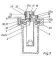
- surge arresters 29 are provided in the plastic housings 20, which are clamped between the respective shielding plate 21 and leaf springs 17, 18. These leaf springs 17, 18 extend with their effective spring leaf upright in the respective plastic housing 20 and are fastened with a lower angled part by the nut 32 to the respective connecting pin 24, 24 '. Pins 30, 31 formed on the bottom of the lower housing part 20b serve to fix the position of the leaf springs 17, 18 (FIG. 3).
- connection unit described above represents a pressure-tight cable termination device.
- metal housing 2 mounted on the base plate 1 by means of a plastically deformable seal 5 can be omitted, so that the connection unit can then also be used as a simple connection strip .
- This optional application represents a significant advantage of the invention.
Landscapes
- Engineering & Computer Science (AREA)
- Computer Networks & Wireless Communication (AREA)
- Health & Medical Sciences (AREA)
- Toxicology (AREA)
- Details Of Connecting Devices For Male And Female Coupling (AREA)
- Coupling Device And Connection With Printed Circuit (AREA)
- Cable Accessories (AREA)
- Communication Cables (AREA)
- Multi-Conductor Connections (AREA)
- Connector Housings Or Holding Contact Members (AREA)
- Light Guides In General And Applications Therefor (AREA)
- Insulated Conductors (AREA)
Description
- Die Erfindung betrifft eine Anschlusseinheit für Kabel zur Übertragung von Signalen mit Puls-Code-Modulation - kurz PCM-Kabel genannt.
- Bisher war es üblich, höherpaarige Endverschlüsse mit niederpaarigen PCM-Kabeln zu versehen. So wird in der Praxis beispielsweise an einem Endverschlussfür12 DA (DA=Doppeladern) ein PCM-Kabel mit nur 6 DA angeschlossen. Diese Massnahme ist notwendig, um die erforderlichen elektrischen Werte für die Abschirmung zu gewährleisten. Nachteilig bei dieser bekannten Bauweise sind der Platzbedarf und ein hoher Kostenaufwand.
- Aufgabe der Erfindung ist es, eine Anschlusseinheit für PCM-Kabel mit z. B. 10 DA zu schaffen, welche z.B. für das 30- und für das 120kanalige System geeignet ist und die als druckdichtes Kabelabschlussgerät sowie durch Weglassen von Gehäuseteilen als einfache Anschlussleiste verwendet werden kann.
- Diese Aufgabe wird erfindungsgemäss dadurch gelöst, dass auf einer Grundplatte mehrere metallisch abgeschirmte Kunststoffgehäuse befestigt sind, dass in jedem Kunststoffgehäuse je zwei in der Grundplatte druckdicht und isoliert befestigte Anschlussstifte sowie mit diesen elektisch verbundene Klemmkontakte aufgenommen sind, und dass an der Unterseite der Grundplatte eine aus mehreren Zwischenwänden gebildete metallische Abschirmung für die Anschlussstifte und die mit diesen verbundenen Kabeladern vorgesehen ist.
- Die angestrebten hohen Abschirmwerte werden durch das Vorsehen der gesonderten Kunststoffgehäuse sowie durch die aus einer entsprechenden Anzahl an Zwischenwänden bestehende Abschirmung erreicht, welche den Raum unterhalb der Grundplatte in eine den Kunststoffgehäusen entsprechende Anzahl von zum Kabelende hin offenen Kammern unterteilen.
- Die angestrebten Abschirmwerte werden noch verbessert durch Abschirmbleche, die in jedem Kunststoffgehäuse angeordnet und an einen gemeinsamen Schirmverbinder angeschlossen sind.
- Weitere vorteilhafte Ausgestaltungen der Erfindung sind Gegenstand von Unteransprüchen.
- Im folgenden wird ein Ausführungsbeispiel der Erfindung anhand der Zeichnung im einzelnen beschrieben.
- Es zeigen:
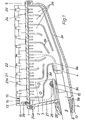
- Fig. 1 eine als druckdichtes Kabelabschlussgerät ausgebildete Anschlusseinheit im Längsschnitt;
- Fig. 2 eine Draufsicht auf das Kabelabschlussgerät nach Fig. 1;
- Fig. 3 das Kabelabschlussgerät nach Fig. 1 im Querschnitt;
- Fig. 4 eine teilgeschnittene Stirnansicht des Kabelabschlussgerätes nach Fig. 1.
- Das in der Zeichnung dargestellte Kabelabschlussgerät besteht aus einer rechteckigen Grundplatte 1, in der eine Reihe von Anschlussstiften 24, 24' paarweise befestigt sind, aus einer Reihe von metallisch abgeschirmten Kunststoffgehäusen 20 auf der Oberseite der Grundplatte 1, in denen in den oberen Enden die Anschlussstifte 24, 24' sowie elektrische Klemmkontakte 13, 14, 15 angeordnet sind, und aus einer metallischen Abschirmung 3 an der Unterseite der Grundplatte 1.
- Ferner ist bei der dargestellten Ausführung ander rechteckigen Grundplatte 1 ein die Abschirmung 3 druckdicht aufnehmendes Metallgehäuse 2 befestigt, das eine druckdichte Kabeleinführung 7,8 für ein PCM-Kabel 9 aufweist.
- Die metallische Abschirmung 3 umfasst mehrere gebogene bzw. verformte Bleche 3b, 3c, 3d, die den Raum unter der Grundplatte 1 in eine den Paaren an Anschlussstiften 24, 24' entsprechende Anzahl von Kammern 3a unterteilen. In jede dieser Kammern 3a ragt ein Paar Anschlussstifte 24, 24' hinein, an denen die Adern 9a der einzelnen PCM-Kabel durch z.B. eine Lötverbindung befestigt sind. Die einzelnen Bleche 3b bis 3d der metallischen Abschirmung 3 sind mittels Schrauben 25 elektrisch leitend mit der Grundplatte 1 verbunden (vgl. Fig. 3). Die beiden äusseren Bleche 3c und 3d der Abschirmung 3 münden in einen gemeinsamen hülsenförmigen Teil 4, auf dem das Abschirmband des PCM-Kabels 9 mittels einer - nicht dargestellten - Schlauchklemme befestigt ist und durch dessen Innenraum die Doppeladern 9a der Einzelkabel hindurchgeführt sind.
- Bei der dargestellten Ausführung eines Kabelanschlussgerätes wird das PCM-Kabel 9 durch eine Stirnwand in das Metallgehäuse 2 eingeführt. Zur Abdichtung des PCM-Kabels 9 gegenüber dem Gehäuseinneren dient ein aussen an der Gehäusewand befestigter Deckel 7 mit konischer Innenwand 12, der mit einer das Kabel 9 fest umschliessenden Dichtungsmasse 8 gefüllt ist. Zur Aufnahme von am PCM-Kabel 9 angreifenden Zugkräften ist der Kabelmantel 9b über eine Lasche 9c an einem Winkelprofil 10 angeschraubt, welches an einer Seitenwand der Abschirmung 3 befestigt ist. Zwischen zwei Muttern 26,26' dieser Befestigungsschraube ist ein elektrischer Leiter 27 eingespannt, der an einen zusätzlichen, in der Grundplatte 1 befestigten Anschlussstift 24a angeschlossen ist, so dass eine elektrische Verbindung zwischen dem Aluminiummantel 9b des PCM-Kabels 9 und Schaltkontakten 13, 14, 15 hergestellt ist, die oberhalb des Anschlussstiftes 24a in einem zusätzlich auf der Grundplatte 1 montierten Kunststoffgehäuse 19 angeordnet sind.
- Die Anschlussstifte 24, 24', 24a tragen ein Gewinde und dienen zusätzlich zu ihrer elektrischen Leiterfunktion zur Befestigung der einzelnen Kunststoffgehäuse 19, 20 auf der Grundplatte 1 mittels aufgeschraubter Muttern 32 (vgl. Fig. 3).
- Wie aus Fig. 2 ersichtlich, ist jedes aus einem Oberteil 20a und einem Unterteil 20b bestehende Kunststoffgehäuse 20 von einem dünnen Abschirmblech 21 aus z.B. Kupfer umgeben, das unter den jeweiligen Gehäuseoberteil 20a greift und so an diesem festgelegt ist. Die Abschirmbleche 21 sind über Klemmverbindungen 21 a an einen gemeinsamen Schirmverbinder 22 angeschlossen, der durch zwei Schrauben 23 elektrisch leitend am Metallgehäuse 2 befestigt ist. Das Gehäuseoberteil 20a ist mittels Haken 20c an dem auf der Grundplatte 1 angeschraubten Gehäuseunterteil 20b festgelegt (Fig. 1 und 4).
- Die in jedem der Kunststoffgehäuse 20 angeordneten elektrischen Kontakte 13,14,15 sind als sog. LSA-PLUS-Kontakte ausgebildet. Diese speziellen löt-, schraub- und abisolierfreien Kontakte ermöglichen die Herstellung von elektrischen Verbindungen zwischen einem isolierten Leiterdraht und dem Kontakt, ohne dass zuvor die Drahtisolierung entfernt werden müsste. Zur Herstellung dieser elektrischen Verbindung wird das jeweilige Leiterdrahtende quer in einen Schlitz zwischen zwei aufrechten federnden Zungen hineingedrückt. An den Zungen sind seitliche Schneidkanten ausgebildet, welche beim Eindrücken des Drahtstückes in den Schlitz die Isolierung durchschneiden und eineformschlüssige Kontaktierung mit dem Leiterwerkstoff herbeiführen.
- An die beiden LSA-PLUS-Kontakte 13,14 gemäss Fig. 2 werden die a- und b-Adern und an den Kontakt 15 wird der Erdbeidraht eines abgehenden Kabels angeschlossen. Die elektrische Verbindung zwischen den Anschlussstiften 24, 24' und den LSA-PLUS-Kontakten 13, 14 erfolgt durch je einen Verbindungsstecker 11, der in einer Querwand im Gehäuseoberteil 20a festgelegt ist. Die LSA-PLUS-Kontakte 15 der Erdbeidrähte sind über abgewinkelte Stege an ihren unteren Enden isoliert durch die Abschirmbleche 21 der jeweiligen Kunststoffgehäuse hindurchgeführt und über eine gemeinsame Erdschiene 16 an den Kontakt im zusätzlichen Kunststoffgehäuse 19 ohne Abschirmung angeschlossen. Durch einen weiteren Verbindungsstecker 11 können die Erdbeidrähte bzw. die Erdschiene 16 elektrisch mit einem in der Grundplatte 1 bzw. im Metallgehäuse 2 sitzenden Stift 28 verbunden werden, der als einziger im zusätzlichen Kunststoffgehäuse 19 elektrisch leitend mit der Grundplatte 1 verbunden ist.
- Zum Schutz der a- und b-Adern der ankommenden Kabel 9a sind Überspannungsableiter 29 in den Kunststoffgehäusen 20 vorgesehen, die zwischen dem jeweiligen Abschirmblech 21 und Blattfedern 17, 18 eingeklemmt sind. Diese Blattfedern 17,18 erstrecken sich mit ihrem wirksamen Federblatt aufrecht im jeweiligen Kunststoffgehäuse 20 und sind mit einem unteren abgewinkelten Teil durch die Mutter 32 am jeweiligen Anschlussstift 24, 24' befestigt. Zur Lagefixierung der Blattfedern 17, 18 dienen am Boden des Gehäuseunterteils 20b angeformte Zapfen 30, 31 (Fig. 3).
- Wie angegeben, stellt die vorstehend beschriebene Anschlusseinheit ein druckdichtes Kabelabschlussgerät dar. Je nach dem Anwendungsort und -zweck kann das mittels einer plastisch verformaren Dichtung 5 an der Grundplatte 1 montierte Metallgehäuse 2 weggelassen werden, so dass dann die Anschlusseinheit auch als einfache Anschlussleiste eingesetzt werden kann. Diese wahlweise Einsatzmöglichkeit stellt einen wesentlichen Vorteil der Erfindung dar.
Claims (11)
Priority Applications (1)
| Application Number | Priority Date | Filing Date | Title |
|---|---|---|---|
| AT81101711T ATE8087T1 (de) | 1980-06-06 | 1981-03-09 | Anschlusseinheit fuer pcm-kabel. |
Applications Claiming Priority (2)
| Application Number | Priority Date | Filing Date | Title |
|---|---|---|---|
| DE3021283 | 1980-06-06 | ||
| DE3021283A DE3021283C2 (de) | 1980-06-06 | 1980-06-06 | Anschlußeinheit als Anschlußleiste und/oder als druckdichtes Kabelabschlußgerät für PCM-Kabel |
Publications (2)
| Publication Number | Publication Date |
|---|---|
| EP0041595A1 EP0041595A1 (de) | 1981-12-16 |
| EP0041595B1 true EP0041595B1 (de) | 1984-06-20 |
Family
ID=6103982
Family Applications (1)
| Application Number | Title | Priority Date | Filing Date |
|---|---|---|---|
| EP81101711A Expired EP0041595B1 (de) | 1980-06-06 | 1981-03-09 | Anschlusseinheit für PCM-Kabel |
Country Status (9)
| Country | Link |
|---|---|
| US (1) | US4405187A (de) |
| EP (1) | EP0041595B1 (de) |
| JP (1) | JPS5717577A (de) |
| AT (1) | ATE8087T1 (de) |
| AU (1) | AU6853981A (de) |
| CA (1) | CA1168327A (de) |
| DE (1) | DE3021283C2 (de) |
| DK (1) | DK148863C (de) |
| GB (1) | GB2077522B (de) |
Families Citing this family (35)
| Publication number | Priority date | Publication date | Assignee | Title |
|---|---|---|---|---|
| FR2512595A1 (fr) * | 1981-09-04 | 1983-03-11 | Cit Alcatel | Borne modulaire de raccordement electrique |
| US4712847A (en) * | 1986-05-07 | 1987-12-15 | Technology For Energy Corporation | Electrical connector |
| US4789358A (en) * | 1986-09-25 | 1988-12-06 | Siemens Aktiengesellschaft | Cable plug |
| US5009616A (en) * | 1989-12-14 | 1991-04-23 | Amp Incorporated | Connector assembly with back shell having vanes |
| US5328380A (en) * | 1992-06-26 | 1994-07-12 | Porta Systems Corp. | Electrical connector |
| FI96458C (fi) * | 1994-09-16 | 1996-06-25 | Nokia Telecommunications Oy | Häiriösuojattu kaapeliliitinkotelo |
| DE19630202C2 (de) * | 1996-07-26 | 1999-09-23 | Harting Kgaa | Leitungsverzweiger |
| US5971797A (en) * | 1998-03-16 | 1999-10-26 | Lucent Technologies Inc. | Connector with cable strain relief |
| US6314182B1 (en) * | 1998-08-19 | 2001-11-06 | 3M Innovative Properties Company | External filter box |
| FR2792465B1 (fr) * | 1999-04-13 | 2001-06-15 | Radiall Sa | Element de connecteur multicontact avec moyen de connexion a la masse de son boitier |
| US6165018A (en) * | 1999-04-27 | 2000-12-26 | Lucent Technologies Inc. | Connector having internal crosstalk compensation |
| AUPQ819900A0 (en) | 2000-06-16 | 2000-07-13 | Krone (Australia) Technique Pty Limited | Multi wire insulation displacement contact and a method of making multi wire erminations |
| US6431885B1 (en) | 2000-06-27 | 2002-08-13 | X-Com Systems, Inc. | Electrical component grounding device, electrical system grounding and support apparatus, and antenna component grounding system |
| US6751392B1 (en) * | 2000-09-18 | 2004-06-15 | Molex Incorporated | Cable management system for connector assemblies |
| US7273393B2 (en) * | 2003-08-29 | 2007-09-25 | 3M Innovative Properties Company | Connector shell for a multiple wire cable assembly |
| US20060030199A1 (en) * | 2004-08-05 | 2006-02-09 | Adc Gmbh | Multi wire insulation displacement contact and a method of making multi wire terminations |
| AU2007247541B2 (en) * | 2006-05-09 | 2010-09-30 | Commscope Technologies Llc | Electrical connector |
| RS51253B (sr) * | 2006-07-25 | 2010-12-31 | Adc Gmbh. | Blok spojnice |
| US7901254B2 (en) * | 2006-07-25 | 2011-03-08 | Adc Gmbh | Connector block |
| AU313574S (en) | 2006-07-25 | 2007-04-10 | Tyco Electronics Services Gmbh | Connector block |
| EP2064780A1 (de) * | 2006-09-19 | 2009-06-03 | ADC GmbH | Abschirmung |
| US8087945B2 (en) * | 2007-03-14 | 2012-01-03 | Adc Gmbh | Electric connector with a dust cover |
| US7942693B2 (en) * | 2007-05-04 | 2011-05-17 | Adc Gmbh | Power outlet with conductive socket contacts coupled to IDC contacts coupled to insulated conductors disposed in channels |
| AU315263S (en) | 2007-05-04 | 2007-07-23 | Tyco Electronics Services Gmbh | Contact assembly |
| AU315267S (en) | 2007-05-07 | 2007-07-23 | Adc Gmbh | Electrical connector |
| TWI422105B (zh) * | 2008-06-13 | 2014-01-01 | Furutech Co Ltd | Power plug |
| JP5588773B2 (ja) * | 2010-07-28 | 2014-09-10 | タイコエレクトロニクスジャパン合同会社 | ワイヤカバー、電気コネクタ |
| EP2645510B1 (de) * | 2010-11-26 | 2018-07-11 | Mitsubishi Electric Corporation | Elektrischer verbinder, zugauskunftssende-/empfangssystem, und verfahren zum anschliessen eines elektrischen verbinders |
| US8123536B1 (en) * | 2011-02-09 | 2012-02-28 | Itt Manufacturing Enterprises, Inc. | Connector with isolated grounds |
| US8333607B1 (en) | 2011-02-28 | 2012-12-18 | Ortronics, Inc. | Connector with pivotable wings, a locking cam nut and a deflectable contact ring |
| US9039442B2 (en) | 2011-11-10 | 2015-05-26 | Carmen Rapisarda | Solder-less electrical assembly |
| US8789965B2 (en) | 2011-11-10 | 2014-07-29 | Carmen Rapisarda | mSolder-less electrical assembly and process for its manufacture |
| US9680268B1 (en) | 2016-05-18 | 2017-06-13 | Itt Manufacturing Enterprises Llc | Genderless electrical connectors |
| US10830482B2 (en) * | 2019-01-03 | 2020-11-10 | Johnson Controls Technology Company | HVAC cable grounding systems and methods |
| BE1029279B1 (nl) * | 2021-04-07 | 2022-11-17 | 1Enclose Bv | Kabeldoorvoer voor water- en stofdichte doorvoer van een kabel, behuizing met kabeldoorvoer, en werkwijze voor voeren van een kabel doorheen een kabeldoorvoer |
Family Cites Families (14)
| Publication number | Priority date | Publication date | Assignee | Title |
|---|---|---|---|---|
| US2876274A (en) * | 1956-03-30 | 1959-03-03 | Bendix Aviat Corp | Shielded electric connector |
| DE1181768B (de) * | 1961-04-12 | 1964-11-19 | Krone Kg | Endverschluss fuer Fernmeldekabel |
| DE1143883B (de) * | 1961-04-22 | 1963-02-21 | Krone Kg | Trennendverschluss fuer Fernmeldekabel |
| US3237146A (en) * | 1963-08-09 | 1966-02-22 | Randolph G Barker | Terminal |
| DE1911312B2 (de) * | 1969-03-06 | 1971-07-08 | Wettersicherer kabelendverteiler fuer fernmelde kabel | |
| DE6921599U (de) * | 1969-05-29 | 1970-02-05 | Krone Kg | Abdichtung fuer fernmeldekabel-endverteiler |
| DE2228498C3 (de) * | 1972-06-12 | 1974-10-31 | Krone Gmbh, 1000 Berlin | Endverzweiger mit Überspannungsschutz für Fernmeldekabel |
| DE2242695A1 (de) * | 1972-08-30 | 1974-03-21 | Krone Gmbh | Endverschluss fuer fernmeldekabel |
| DE2329334A1 (de) * | 1973-06-08 | 1975-01-02 | Daimler Benz Ag | Zentralsteckverbindung |
| US3927925A (en) * | 1973-11-19 | 1975-12-23 | Leslie M Borsuk | Connector assembly |
| DE2638155A1 (de) * | 1976-08-25 | 1978-03-02 | Felten & Guilleaume Carlswerk | Endverzweiger fuer fernmeldekabel |
| DE2811812C2 (de) * | 1978-03-16 | 1984-04-12 | Krone Gmbh, 1000 Berlin | Kabelendeinrichtung der Fernmeldelinientechnik |
| FR2421483A1 (fr) * | 1978-03-31 | 1979-10-26 | Cit Alcatel | Connecteur pour cable electrique |
| DE2816724C2 (de) * | 1978-04-18 | 1982-07-08 | Krone Gmbh, 1000 Berlin | Verbindungs- und Verteilerdose für Fernmeldekabel |
-
1980
- 1980-06-06 DE DE3021283A patent/DE3021283C2/de not_active Expired
-
1981
- 1981-03-09 AT AT81101711T patent/ATE8087T1/de not_active IP Right Cessation
- 1981-03-09 EP EP81101711A patent/EP0041595B1/de not_active Expired
- 1981-03-16 DK DK117781A patent/DK148863C/da not_active IP Right Cessation
- 1981-03-19 AU AU68539/81A patent/AU6853981A/en not_active Abandoned
- 1981-03-20 CA CA000373557A patent/CA1168327A/en not_active Expired
- 1981-03-23 US US06/246,248 patent/US4405187A/en not_active Expired - Fee Related
- 1981-04-28 GB GB8113077A patent/GB2077522B/en not_active Expired
- 1981-05-14 JP JP7286381A patent/JPS5717577A/ja active Pending
Also Published As
| Publication number | Publication date |
|---|---|
| CA1168327A (en) | 1984-05-29 |
| US4405187A (en) | 1983-09-20 |
| DK117781A (da) | 1981-12-07 |
| DK148863C (da) | 1986-04-21 |
| DE3021283C2 (de) | 1983-11-24 |
| JPS5717577A (en) | 1982-01-29 |
| GB2077522A (en) | 1981-12-16 |
| DE3021283A1 (de) | 1981-12-17 |
| AU6853981A (en) | 1981-12-10 |
| DK148863B (da) | 1985-10-28 |
| EP0041595A1 (de) | 1981-12-16 |
| GB2077522B (en) | 1984-03-14 |
| ATE8087T1 (de) | 1984-07-15 |
Similar Documents
| Publication | Publication Date | Title |
|---|---|---|
| EP0041595B1 (de) | Anschlusseinheit für PCM-Kabel | |
| DE3614592C1 (de) | Anschlussleiste fuer Kabeladern,insbesondere von Fernsprechkabeln | |
| EP0643454B1 (de) | Klemmanschlusseinheit | |
| DE19617114C2 (de) | Erdungsmodul | |
| DE3306263A1 (de) | Endverzweiger mit lsa-plus-anschlusstechnik | |
| DE3301362C2 (de) | Kabelverteiler, bzw. -abzweiger | |
| DE19506859A1 (de) | Elektr. Steckverbinder | |
| EP0321743B1 (de) | Anschlussleiste für ankommende und abgehende elektrische Leitungen | |
| EP0071737B1 (de) | Endverzweiger für Fernmeldekabel, insbesondere für Freiluftkabel (Dropwire-Kabel) | |
| DE4440602C2 (de) | Einrichtung zum Sichern von elektrischen Leitungen | |
| EP0597327B1 (de) | Modulare Mehrfachanschlussleiste für Verteiler und Verteilersysteme im Schwachstrom-Anlagebau | |
| EP0667650A2 (de) | Modulares Anschlusssystem | |
| DE2201504C2 (de) | Anschlussleiste mit ueberspannungsschutzvorrichtung | |
| EP0905822A1 (de) | Kabelstecker mit Massekontaktierung | |
| DE9418316U1 (de) | Vorrichtung zum Anschluß von elektrischen Installationsgeräten | |
| DE1911312C (de) | ||
| DE2719269A1 (de) | Als gemeinsame betriebserde fuer die erdtasten mehrerer amtsberechtigter nebenstellen ausgebildete rangierleiste | |
| DE2816724A1 (de) | Verbindungs- und verteilerdose fuer fernmeldekabel | |
| DE3128916C2 (de) | ||
| EP0209741A2 (de) | Anschlussleiste für Telekommunikationsanlagen | |
| DE2362492C3 (de) | Kabelendeinsatz der elektrischen Nachrichtentechnik | |
| EP1277254B1 (de) | Abzweigklemme für niederspannungs-energiekabel | |
| DE8714093U1 (de) | Elektrische Reihenklemme | |
| DE3210224C2 (de) | Kabelgarnitur mit Schirmanschluß | |
| DE2710973A1 (de) | Fernmeldetechnische klemmenleiste mit aufsteckbarer ueberspannungsschutzeinrichtung |
Legal Events
| Date | Code | Title | Description |
|---|---|---|---|
| PUAI | Public reference made under article 153(3) epc to a published international application that has entered the european phase |
Free format text: ORIGINAL CODE: 0009012 |
|
| AK | Designated contracting states |
Designated state(s): AT BE CH FR IT LU NL SE |
|
| 17P | Request for examination filed |
Effective date: 19820401 |
|
| ITF | It: translation for a ep patent filed | ||
| GRAA | (expected) grant |
Free format text: ORIGINAL CODE: 0009210 |
|
| AK | Designated contracting states |
Designated state(s): AT BE CH FR IT LI LU NL SE |
|
| REF | Corresponds to: |
Ref document number: 8087 Country of ref document: AT Date of ref document: 19840715 Kind code of ref document: T |
|
| ET | Fr: translation filed | ||
| PG25 | Lapsed in a contracting state [announced via postgrant information from national office to epo] |
Ref country code: AT Effective date: 19850309 |
|
| PG25 | Lapsed in a contracting state [announced via postgrant information from national office to epo] |
Ref country code: SE Effective date: 19850310 |
|
| PG25 | Lapsed in a contracting state [announced via postgrant information from national office to epo] |
Ref country code: LU Free format text: LAPSE BECAUSE OF NON-PAYMENT OF DUE FEES Effective date: 19850331 Ref country code: LI Effective date: 19850331 Ref country code: CH Effective date: 19850331 Ref country code: BE Effective date: 19850331 |
|
| PLBE | No opposition filed within time limit |
Free format text: ORIGINAL CODE: 0009261 |
|
| STAA | Information on the status of an ep patent application or granted ep patent |
Free format text: STATUS: NO OPPOSITION FILED WITHIN TIME LIMIT |
|
| 26N | No opposition filed | ||
| BERE | Be: lapsed |
Owner name: KRONE G.M.B.H. Effective date: 19850309 |
|
| PG25 | Lapsed in a contracting state [announced via postgrant information from national office to epo] |
Ref country code: NL Effective date: 19851001 |
|
| PG25 | Lapsed in a contracting state [announced via postgrant information from national office to epo] |
Ref country code: FR Free format text: LAPSE BECAUSE OF NON-PAYMENT OF DUE FEES Effective date: 19851129 |
|
| REG | Reference to a national code |
Ref country code: CH Ref legal event code: PL |
|
| NLV4 | Nl: lapsed or anulled due to non-payment of the annual fee | ||
| REG | Reference to a national code |
Ref country code: FR Ref legal event code: ST |
|
| EUG | Se: european patent has lapsed |
Ref document number: 81101711.0 Effective date: 19860128 |