EP0041417B1 - Building block with insulating material incorporated therein for exterior insulation - Google Patents
Building block with insulating material incorporated therein for exterior insulation Download PDFInfo
- Publication number
- EP0041417B1 EP0041417B1 EP81400726A EP81400726A EP0041417B1 EP 0041417 B1 EP0041417 B1 EP 0041417B1 EP 81400726 A EP81400726 A EP 81400726A EP 81400726 A EP81400726 A EP 81400726A EP 0041417 B1 EP0041417 B1 EP 0041417B1
- Authority
- EP
- European Patent Office
- Prior art keywords
- bearing part
- facing
- insulating plate
- designed
- wall
- Prior art date
- Legal status (The legal status is an assumption and is not a legal conclusion. Google has not performed a legal analysis and makes no representation as to the accuracy of the status listed.)
- Expired
Links
Images
Classifications
-
- E—FIXED CONSTRUCTIONS
- E04—BUILDING
- E04C—STRUCTURAL ELEMENTS; BUILDING MATERIALS
- E04C1/00—Building elements of block or other shape for the construction of parts of buildings
- E04C1/40—Building elements of block or other shape for the construction of parts of buildings built-up from parts of different materials, e.g. composed of layers of different materials or stones with filling material or with insulating inserts
- E04C1/41—Building elements of block or other shape for the construction of parts of buildings built-up from parts of different materials, e.g. composed of layers of different materials or stones with filling material or with insulating inserts composed of insulating material and load-bearing concrete, stone or stone-like material
Abstract
Description
La présente invention concerne les blocs de construction à isolant incorporé. Par blocs de construction, on entend ici les éléments susceptibles d'être montés de façon traditionnelle par un maçon, avec un mortier usuel.The present invention relates to building blocks with incorporated insulation. By building blocks is meant here the elements capable of being assembled in the traditional way by a mason, with a usual mortar.
La présente invention a notamment pour objet un bloc du type comportant une partie portante placée du côté intérieur du mur et une planelle placée à l'extérieur, ces dernières étant disposées sur chaque face d'une plaque isolante et reliées l'une à l'autre par celle-ci.The subject of the present invention is in particular a block of the type comprising a bearing part placed on the inside of the wall and a plane placed on the outside, the latter being arranged on each side of an insulating plate and connected one to the other. other by this one.
On connît déjà des blocs de construction de ce type dans lesquels la partie portante est destinée à être disposée du côté extérieur d'une construction, par exemple au mur de bâtiment, tandis que la planelle forme contre-cloison. Des liaisons de type tenonmortaise relient les deux faces de la plaque isolante respectivement à la partie portante et à la contrecloison. De tels blocs sont notamment décrits dans le FR-A-2 341 714.Building blocks of this type are already known in which the bearing part is intended to be placed on the outside of a construction, for example on the wall of a building, while the plane forms a counter-partition. Tenon-type connections link the two faces of the insulating plate respectively to the load-bearing part and to the counter-partition. Such blocks are notably described in FR-A-2 341 714.
L'utilisation de ces blocs connus apporte certes des résultats appréciables sur le plan de l'isolation thermique, mais quelques inconvénients subsistent.The use of these known blocks certainly provides appreciable results in terms of thermal insulation, but some drawbacks remain.
Ainsi, si l'on cherche à réaliser une isolation très poussée, des difficultés sont rencontrées au niveau des planchers. En effet, ceux-ci doivent nécessairement s'appuyer sur les parties portantes, ce qui crée inévitablement des ponts thermiques aux abouts de planchers.Thus, if one seeks to achieve very advanced insulation, difficulties are encountered at the level of the floors. Indeed, these must necessarily rest on the load-bearing parts, which inevitably creates thermal bridges at the ends of floors.
Par ailleurs, les parties extérieures soumises aux variations thermiques et sujettes aux fissurations sont les parties assurant la fonction portante.Furthermore, the external parts subjected to thermal variations and subject to cracking are the parts ensuring the load-bearing function.
Enfin, les contre-cloisons situées du côté intérieur sont des parties d'épaisseur réduite et ne peuvent pas constituer des revêtements ayant une inertie thermique notable.Finally, the counter-partitions located on the interior side are parts of reduced thickness and cannot constitute coatings having a significant thermal inertia.
Il a été proposé (FR-A-2 357 695) de remédier à ces inconvénients en disposant la partie portante du côté intérieur. Ainsi la continuité de l'isolant peut ne pas être interrompue au niveau des abouts de planchers et les parties portantes constituent un revêtement intérieur non exposé aux chocs thermiques et d'inertie thermique appréciable. Toutefois, cette solution peut entrâiner l'apparition de graves désordres dans le revêtement formé par les planelles extérieures. En effet, ce revêtement extérieur mince est exposé aux chocs thermiques, lesquels peuvent être particulièrement sévères dans le cas de murs exposés au soleil, les températures minimales e maximales pouvant facilement différer de quelques dizaines de degrés. Le revêtement extérieur est alors amené à se fissures très rapidement. Pour augmenter la solidité de ce revêtement, il a bien été suggéré de relier chaque planelle à la partie portante non seulement par la plaque isolante, mais aussi par des broches métalliques, ce qui revient alors à créer un très grand nombre de petits ponts thermiques et constitue donc une solution inacceptable.It has been proposed (FR-A-2 357 695) to remedy these drawbacks by placing the bearing part on the interior side. Thus, the continuity of the insulation may not be interrupted at the level of the floor ends and the load-bearing parts constitute an interior coating not exposed to thermal shock and appreciable thermal inertia. However, this solution can lead to the appearance of serious disorders in the coating formed by the outer planelles. In fact, this thin exterior coating is exposed to thermal shocks, which can be particularly severe in the case of walls exposed to the sun, the minimum and maximum temperatures being able to easily differ by a few tens of degrees. The outer coating is then caused to crack very quickly. To increase the solidity of this coating, it has been suggested to connect each planelle to the bearing part not only by the insulating plate, but also by metal pins, which then amounts to creating a very large number of small thermal bridges and therefore constitutes an unacceptable solution.
Aussi suivant un de ses aspects, la présente invention a alors pour but de fournir un bloc de construction du type indiqué en tète de la description et selon le FR-A-2 357 695, bloc qui puisse être utilisé avec la planelle située du côté extérieur, c'est-à-dire avec isolation par l'extérieur, avec tous les avantages qui en découlent mais sans entraîner l'apparition de désordres dans le revêtement extérieur et sans nécessiter l'utilisation de moyens supplémentaires comme des liaisons métalliques entre planelles et parties portantes.Also according to one of its aspects, the present invention therefore aims to provide a building block of the type indicated at the head of the description and according to FR-A-2 357 695, block which can be used with the planelle located on the side exterior, that is to say with insulation from the outside, with all the advantages which ensue therefrom but without causing the appearance of disorders in the external coating and without requiring the use of additional means such as metallic connections between planelles and load-bearing parts.
Ce but est atteint du fait que, conformément à la présente invention, plusieurs lames d'air sont ménagées entre les faces en regard de la plaque isolante et de la planelle de manière à constituer, lorsque plusieurs blocs sont assemblés, des conduits formés par lesdites lames d'air alignées, et dans lesquels l'air peut circuler par convection pour réduire l'écart entre les températures régnant sur les faces opposées des planelles des blocs assemblés et éviter une détérioration des planelles en raison de contraintes thermiques.This object is achieved by the fact that, in accordance with the present invention, several air spaces are provided between the facing faces of the insulating plate and of the planar so as to constitute, when several blocks are assembled, conduits formed by said aligned air knives, and in which the air can circulate by convection to reduce the difference between the temperatures prevailing on the opposite faces of the planelles of the assembled blocks and to avoid a deterioration of the planelles due to thermal stresses.
Ces conduits peuvent éventuellement communiquer avec l'éxtérieur.These conduits can possibly communicate with the outside.
L'équilibrage des températures de part et d'autre des planelles évite ainsi l'apparition de désordres d'origine thermique lorsque les planelles sont situées du côté extérieur.Balancing the temperatures on both sides of the planelles thus avoids the appearance of thermal disorders when the planelles are located on the outside.
De préférence, les lames d'air s'étendent verticalement entre les faces inférieure et supérieure du bloc. Dans le cas où la liaison entre la plaque isolante et la planelle est réalisée au moyen de nervures en saillie parallèles entre elles et encastrées dans des rainures correspondantes de la planelle, les lames d'air peuvent être ménagées entre nervures voisines.Preferably, the air knives extend vertically between the lower and upper faces of the block. In the case where the connection between the insulating plate and the planar is made by means of projecting ribs parallel to each other and embedded in corresponding grooves of the planar, the air gaps can be formed between neighboring ribs.
L'invention concerne non seulement les blocs de construction standards, mais s'applique également à des blocs spéciaux destinés aux points singuliers.The invention relates not only to standard building blocks, but also applies to special blocks intended for singular points.
Ainsi, suivant un autre de ses aspects, l'invention a aussi pour objet un bloc d'angle préfabriqué comportant un élément de construction extérieur et un élément isolant formé chacun de deux parties perpendiculaires entre elles et reliés l'un à l'autre, bloc caractérisé en ce que plusieurs lames d'air sont ménagées entre les faces en regard de l'élément isolant et de l'élément de construction selon la revendication 2.Thus, according to another of its aspects, the invention also relates to a prefabricated corner block comprising an external construction element and an insulating element each formed by two parts perpendicular to each other and connected to each other, block characterized in that several air spaces are provided between the facing faces of the insulating element and of the construction element according to
Dans ce bloc d'angle, les faces à angle droit de l'élément isolant opposées à celles reliées à l'élément de construction sont libres et constituent, lorsque plusieurs blocs d'angle sont superposés, deux parois d'un coffrage dans lequel un poteau peut être coulé. On retrouve alors la structure partie portante (poteau) -isolant-élément extérieur.In this corner block, the right-angled faces of the insulating element opposite to those connected to the construction element are free and constitute, when several corner blocks are superimposed, two walls of a formwork in which a post can be poured. We then find the supporting part structure (post) -insulator-external element.
Suivant encore un autre de ses aspects, l'invention a aussi pour objet un bloc, dit bloc «tableau», conformé pour la délimitation verticale d'un dormant, bloc qui comporte une partie portante et une planelle disposées sur chaque face d'une plaque isolante et reliées l'une à l'autre par celle-ci et qui est caractérisé par un décrochement vertical formé d'un côté du bloc sur toute la hauteur de celui-ci pour le logement d'un prolongement intérieur de la plaque isolante entre ledit côté du bloc et un rebord intérieur de la planelle, et plusieurs lames d'air sont ménagées entre les faces en regard de la plaque isolante et de la planelle selon la revendication 3.According to yet another of its aspects, the invention also relates to a block, known as a “table” block, shaped for the vertical delimitation of a frame, a block which comprises a bearing part and a plane arranged on each face of a insulating plate and connected to each other by the latter and which is characterized by a vertical recess formed on one side of the block over the entire height thereof for housing an interior extension of the insulating plate between said side of the block and an inner rim of the planelle, and more several air knives are provided between the facing faces of the insulating plate and of the plate according to claim 3.
Par l'utilisation des blocs standards et spéciaux conformes à l'invention, on peut ainsi réaliser les murs extérieurs d'un bâtiment avec une parfaite continuité de l'isolant incorporé dans les murs et en disposant les parties portantes des blocs du côté intérieur.By using the standard and special blocks in accordance with the invention, the exterior walls of a building can thus be produced with perfect continuity of the insulation incorporated into the walls and by placing the bearing parts of the blocks on the interior side.
D'autres particularités et avantages des blocs de construction conformes à l'invention ressortiront à la lecture de la description faite ci-après, à titre indicatif, en référence aux dessins joints sur lesquels:
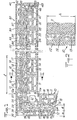
- - la figure 1 est une vue de dessus montrant plusieurs blocs conformes à l'invention placés côte à côte, et
- - la figure 2 est une vue en coupe suivant la ligne 11-11 de la figure 1.
- FIG. 1 is a top view showing several blocks according to the invention placed side by side, and
- - Figure 2 is a sectional view along line 11-11 of Figure 1.
Sur les figures 1 et 2, la référence 10 désigne un bloc de construction standard conforme à l'invention.In Figures 1 and 2, the
Le bloc 10 comporte une partie portante 11 et une planelle 12 entre lesquelles est logée une plaque isolante 13. La liaison entre les éléments constitutifs du bloc 10 est réalisée par des nervures 14, 15 formant tenons sur chaque face de la plaque isolante et engagées dans des rainures 16-17 formant mortaises dans les faces en regard de la partie portante et de la planelle, respectivement.The
Dans l'exemple illustré, les nervures 14, 15 et rainures 16, 17 sont à section transversale en queue d'aronde et s'étendent parallèlement les unes aux autres et verticalement sur toute la hauteur du bloc.In the example illustrated, the
En variante, d'autres formes de section transversale, orientations et/ou longueurs des nervures et rainures pourront être choisies, pour autant que la liaison entre les éléments constitutifs du bloc soit suffisante pour résister aux manipulations de celui-ci jusqu'à son montage sur le chantier. La partie portante et la planelle sont des éléments réalisés en matériau de construction, par exemple béton ou terre cuite, et sont munis, de façon connue, d'alvéoles 18.As a variant, other forms of cross section, orientations and / or lengths of the ribs and grooves may be chosen, provided that the connection between the constituent elements of the block is sufficient to withstand manipulation thereof until it is assembled. on site. The bearing part and the planar are elements made of building material, for example concrete or terracotta, and are provided, in a known manner, with
Les dimensions de la partie portante 11 sont celles d'un bloc usuel sans isolant incorporé.The dimensions of the
La planelle 12 a mêmes hauteur Ji et longueur 1 que la partie portante 11, mais une épaisseur e réduite, par exemple comprise entre 5 et 10 cm.The
La plaque isolante 13 est en un matériau expansé, par exemple polystyrène. L'épaisseur E de la plaque 13 dépend des caractéristiques d'isolation souhaitées. En pratique, cette largeur est choisie entre 5 et 10 cm environ. Avantaugeuse- ment, la plaque 13 a une hauteur et une longueur légèrement supérieures à celles de la planelle et de la partie portante de manière à réserver le place de mortier de liaison entre parties portantes adjacentes, d'une part, et entre parties portantes, d'autre part, sans qu'il y ait de jeu entre les plaques isolantes de blocs disposés côte à côte ou l'un au-dessus de l'autre. L'ensemble partie portante 11 - plaque isolante 13 - planelle 12 forme un bloc susceptible d'être posé de façon traditionnelle par un maçon et dont le poids, à titre indicatif, peut être environ de 25 kg. Des rainures 11 a, 12a sont formées dans les bords latéraux verticaux des parties portantes 11 et planelles 12 pour réserver l'emplacement du mortier de liaison entre blocs disposés côte à côte.The
Pour réaliser un bloc 10, on peut partir d'éléments préfabriqués séparément les uns des autres et assemblés par ajustage en translation de la plaque isolante entre la partie portante et la planelle.To make a
Comme on peut le voir sur les figures 1 et 2, la partie portante 11 et la plaque isolante 13 sont reliées l'une à l'autre sans jeu entre leurs faces en regard.As can be seen in Figures 1 and 2, the bearing
Par contre, conformément à l'invention, des évidements verticaux en forme de rainures à section transversales en U sont prévus dans la face de la plaque isolante 13, sur toute la hauteur du bloc et dans l'intervalle entre nervures 15 parallèles voisines. Ces évidements constituent des lames d'air 19 entre les faces en regard de la planelle 12 et de la plaque isolante 13.On the other hand, in accordance with the invention, vertical recesses in the form of grooves with a U-shaped cross section are provided in the face of the
Lorsque plusieurs blocs sont superposés pour former un mur avec les planelles 12 du côté extérieur, les lames d'air 19 disposées bout à bout constituent des canaux verticaux s'étendant sur toute la hauteur du mur et communiquant éventuellement avec l'extérieur. Cette communication est réalisée soit de façon naturelle, soit en prévoyant des passages à la base et au sommet du mur pour établir une circulation forcée par convection de l'air extérieur dans les lames d'air 19. Dans les deux cas, la présence des lames d'air 19 permet d'éviter l'apparition d'un gradient de température trop important entre les faces intérieures et extérieures des planelles 12. On supprime ainsi une cause de fissuration des planelles et de l'enduit extérieur que les recouvre lorsque le mur est terminé.When several blocks are superimposed to form a wall with the
La largeur de l'isolant utile est celle de la plaque 13 au niveau des lames d'air 19. Une augmentation de l'épaisseur des lames d'air se traduit alors par une même augmentation de l'épaisseur totale du bloc si l'on veut conserver les mêmes caractéristiques d'isolation. C'est pourquoi, il est préférable de limiter l'épaisseur a des lames d'air 19 tout en lui conférant une valeur suffisante pour assurer une «ventilation» satisfaisante. En pratique, on choisira pour a une valeur de préférence comprise entre 1 et 3 cm, par exemple 1,5 à 2 cm.The width of the useful insulation is that of the
Du fait de la disposition des parties portantes 11 du côté intérieur, la continuité de l'isolation peut ne pas être interrompue au niveau des planchers, ceux-ci reposant sur les parties portantes uniquement. A ce niveau, une liaison par agrafes, épingles ou autres armatures, peut être prévue à travers l'isolant entre le plancher et les planelles pour garantir la stabilité de celles-ci.Due to the arrangement of the load-bearing
Une autre particularité avantageuse de l'invention consiste dans la possibilité d'utilisation de blocs particuliers aux points singuliers d'un bâtiment de façon à réaliser la continuité de l'isolant dans tout le mur sans exception.Another advantageous feature of the invention consists in the possibility of using particular blocks at the singular points of a building so as to achieve continuity of the insulation throughout the wall without exception.
Ainsi, comme illustré par la figure 1, on peut superposer aux angles du bâtiment des blocs d'angle en L, tels que 20 constitutés chacun d'un élément de construction extérieur 22, comprenant deux parties perpendiculaires entre elles munies d'alvéoles 28, et d'un élément isolant 23 comprenant également deux parties perpendiculaires entre elles. Les élémentes extérieurs 22 et isolant 23 sont formés chacun en une seule pièce et sont assemblés au moyen de nervures verticales 24, formées sur les faces des deux parties de l'isolant 23 tournées vers l'élément extérieur 22 et engagées dans des rainures 27 formées dans les faces intérieures des deux parties de la planelle 22. Entre les nervures 24, des évidements sont formés dans l'isolant 23 pour constituer des lames d'air verticales 29 entre les faces en regard de l'élément extérieur et de l'élément isolant.Thus, as illustrated in Figure 1, we can superimpose on the corners of the building blocks of an gle in L, such as 20 each consisting of an external construction element 22, comprising two parts perpendicular to each other provided with
Les nervures 24, rainures 27 et lames d'air 29 du bloc sont semblables aux nervures 15, rainures 17 et lames d'air 19 des blocs 10. En outre, l'épaisseur et la hauteur de la planelle 22 et de l'isolant 23 sont égales respectivement à celles des planelles 12 et plaques 13 des blocs 10. Ainsi, le bloc 20 raccorde donc exactement deux blocs standards 10 à l'angle d'un bâtiment, à l'exception de la partie portante. En effet, les faces intérieures de l'isolant sont libres tout en présentant toutefois des nervures verticales 24 analogues aux nervures 14 des blocs 10.The
Les faces intérieures verticales de l'isolant 23 du bloc d'angle 20 et les bords verticaux extrêmes des blocs standards 10 adjacents délimitent un logement dans lequel peut être coulé un poteau 21 après disposition d'armatures 21 a. Du fait de la présence des nervures 24 et des rainures 11a, le poteau une fois coulé est lié à la fois à l'isolant 23 et aux parties portantes 11 adjacentes aux blocs d'angle superposés. On réalise donc ainsi la parfaite continuité de la construction au niveau des angles.The vertical interior faces of the
D'autres points singuliers sont les encadrements des ouvertures formées dans les murs. Avantageusement, la délimitation verticale de ces encadrements est réalisée au moyen de blocs tableau tels que le bloc 30 de la figure 1.Other singular points are the framing of the openings formed in the walls. Advantageously, the vertical delimitation of these frames is carried out by means of table blocks such as
Comme le bloc 10, le bloc 30 comporte une partie portante 31, une planelle 32 présentant toutes deux des alvéoles 38, et une plaque isolante 33 reliant la planelle à la partie portante grâce à des nervures 34, 35 prévues sur chaque face de la plaque 33 et engagées dans des rainures 36, 37 des faces en regard de la partie portante 31 et de la planelle 32. Des évidements sont prévus dans la plaque 33 entre les nervures 35 pour constituer des lames d'air 39 entre les faces en regard de la plaque 33 et de la planelle 32.Like the
Le bloc 30 se distingue du bloc 10 en ce que, du côté bordant l'ouverture 40, la planelle 32 est prolongée par un rebord intérieur 42. De ce même côté, la partie portante 31 présente un décrochement 41 qui s'étend verticalement sur toute la hauteur du bloc et qui permet le longement d'une languette isolante 43 qui forme un rebord intérieur de la plaque isolante 33. La languette 43 et la plaque 33 peuvent ou non être formées en une seule pièce.The
Le rebord 42 s'étend sur une partie seulement de l'épaisseur du bloc 30. Comme on peut le voir sur la figure 1, la face intérieure extrême du rebord 42 et les bords latéraux de la languette 43 et de l'extrémité amincie de la partie portante 31 constituent un logement dans lequel peut être monté un dormant 45 avec interposition d'un matériau d'étanchéité 46. On retrouve donc la continiuité de l'isolant jusqu'à la délimitation verticale du logement du dormant.The
Bien entendu, diverses modifications ou adjonctions pourront être apportées aux modes de réalisation décrits ci-avant d'un bloc de construction conforme à l'invention, sans pour cela sortir du cadre de protection défini par les revendications annexées.Of course, various modifications or additions may be made to the embodiments described above of a building block according to the invention, without thereby departing from the protective framework defined by the appended claims.
Ainsi, les lames d'air entre planelle et plaque isolante pourront être constituées par des rainures formées non dans la plaque isolante, mais dans la planelle.Thus, the air gaps between planar and insulating plate can be formed by grooves formed not in the insulating plate, but in the planar.
Claims (8)
Priority Applications (1)
| Application Number | Priority Date | Filing Date | Title |
|---|---|---|---|
| AT81400726T ATE8805T1 (en) | 1980-05-29 | 1981-05-07 | BUILDING BLOCK WITH INTEGRATED THERMAL INSULATION FOR INSULATION FROM THE OUTSIDE. |
Applications Claiming Priority (2)
| Application Number | Priority Date | Filing Date | Title |
|---|---|---|---|
| FR8011973A FR2485063A1 (en) | 1980-05-29 | 1980-05-29 | BUILDING BLOCK WITH BUILT-IN INSULATION |
| FR8011973 | 1980-05-29 |
Publications (2)
| Publication Number | Publication Date |
|---|---|
| EP0041417A1 EP0041417A1 (en) | 1981-12-09 |
| EP0041417B1 true EP0041417B1 (en) | 1984-08-01 |
Family
ID=9242483
Family Applications (1)
| Application Number | Title | Priority Date | Filing Date |
|---|---|---|---|
| EP81400726A Expired EP0041417B1 (en) | 1980-05-29 | 1981-05-07 | Building block with insulating material incorporated therein for exterior insulation |
Country Status (4)
| Country | Link |
|---|---|
| EP (1) | EP0041417B1 (en) |
| AT (1) | ATE8805T1 (en) |
| DE (1) | DE3165198D1 (en) |
| FR (1) | FR2485063A1 (en) |
Families Citing this family (13)
| Publication number | Priority date | Publication date | Assignee | Title |
|---|---|---|---|---|
| EP0112213B1 (en) * | 1982-11-25 | 1987-04-15 | Vibro Ouest S.A. | Externally insulated breeze-block and process for assembling such a block |
| FI67739C (en) * | 1984-01-17 | 1985-05-10 | Matti Antero Sundberg | BYGGNADSBLOCK |
| FR2558867B1 (en) * | 1984-01-30 | 1987-03-06 | Schneider Charles | PREFABRICATED REINFORCED CONCRETE PANEL WITH PARIETODYNAMIC INSULATION |
| FR2577255B1 (en) * | 1985-02-08 | 1993-09-10 | Manent Vincent | IMPORTANT IMPROVEMENTS IN RESPECT OF ISOTHERMAL ANGLE BLOCKS |
| FR2588901B1 (en) * | 1985-10-21 | 1988-08-05 | Tuilerie Briqueterie Bressane | COMPOSITE BLOCK |
| SE506505C2 (en) * | 1996-09-06 | 1997-12-22 | Polyplank Ab | Method of connecting boards to each other to a building block and according to the method, building blocks made |
| ATE210772T1 (en) * | 1999-09-08 | 2001-12-15 | Fornaci Di Masserano Bruno Tar | HEAT-INSULATING CONSTRUCTION BLOCK |
| KR100458059B1 (en) * | 2004-07-31 | 2004-11-18 | 주식회사 제이지비 | Architectural brick used to building works method |
| KR100505915B1 (en) * | 2004-07-31 | 2005-08-02 | 주식회사 제이지비 | Architectural brick included a container |
| FR2927915B1 (en) * | 2008-02-26 | 2010-03-26 | Alain Sergeant | BUILDING BLOCK WITH INTEGRATED INSULATION. |
| EP2116663A1 (en) | 2008-05-08 | 2009-11-11 | Stamford Consulting Limited | Insulating composite block for the building industry, and method of manufacturing said block |
| AT507526B1 (en) | 2009-03-02 | 2012-09-15 | Hirsch Porozell Gmbh | WALL |
| CN113090076B (en) * | 2021-04-15 | 2022-04-22 | 北京林婉嫕空间艺术设计有限公司 | Modular prefabricated integrated building construction system and construction method thereof |
Citations (1)
| Publication number | Priority date | Publication date | Assignee | Title |
|---|---|---|---|---|
| FR2357695A1 (en) * | 1976-07-08 | 1978-02-03 | Cofirag Sa | Prefabricated building construction system - uses standard lightweight concrete components to form external supporting walls |
Family Cites Families (2)
| Publication number | Priority date | Publication date | Assignee | Title |
|---|---|---|---|---|
| FR2122357B1 (en) * | 1971-01-22 | 1974-12-20 | Toussaint Jacques | |
| FR2341714A1 (en) * | 1976-02-23 | 1977-09-16 | Centre Etd Rech Ind Beton | PREFABRICATED CONSTRUCTION BLOCK AND METHOD AND INSTALLATION FOR ITS MANUFACTURING |
-
1980
- 1980-05-29 FR FR8011973A patent/FR2485063A1/en active Granted
-
1981
- 1981-05-07 EP EP81400726A patent/EP0041417B1/en not_active Expired
- 1981-05-07 DE DE8181400726T patent/DE3165198D1/en not_active Expired
- 1981-05-07 AT AT81400726T patent/ATE8805T1/en not_active IP Right Cessation
Patent Citations (1)
| Publication number | Priority date | Publication date | Assignee | Title |
|---|---|---|---|---|
| FR2357695A1 (en) * | 1976-07-08 | 1978-02-03 | Cofirag Sa | Prefabricated building construction system - uses standard lightweight concrete components to form external supporting walls |
Non-Patent Citations (1)
| Title |
|---|
| L'isolation acoustique et thermique dans le bâtiment par Claude Rougeron Editions Eyrolles - Paris 1977, p. 301 à 303 * |
Also Published As
| Publication number | Publication date |
|---|---|
| EP0041417A1 (en) | 1981-12-09 |
| DE3165198D1 (en) | 1984-09-06 |
| FR2485063B1 (en) | 1983-09-16 |
| ATE8805T1 (en) | 1984-08-15 |
| FR2485063A1 (en) | 1981-12-24 |
Similar Documents
| Publication | Publication Date | Title |
|---|---|---|
| EP0041417B1 (en) | Building block with insulating material incorporated therein for exterior insulation | |
| CH661082A5 (en) | ASSEMBLY OF CONSTRUCTION ELEMENTS, PARTICULARLY FOR THE MAKING OF HOUSES, GARAGES, SHELTERS. | |
| WO1988008063A1 (en) | Insulating modular block for the basic structure and finished structure of a building and process for its utilization | |
| WO2010086533A1 (en) | Module for a modular construction system, and modular construction consisting of said modules | |
| CA2802585C (en) | Prefabricated modular construction element for building a wall | |
| FR2570738A1 (en) | Sandwich-type panels and assembly of these panels | |
| EP1409813B1 (en) | Connecting device for thermal insulating connection between at least two walls of a building, and method for making same | |
| FR2949240A1 (en) | Construction element for constructing e.g. heating wall of building, has studs anchoring pipelines and sheaths before installing facing, where height of each stud defines interstice between front wall and facing to receive pipelines | |
| EP0001723B1 (en) | Prefabricated structural element used as a form | |
| BE1019464A3 (en) | PREFABRICATED ELEMENT HIGHLY ISOLATED. | |
| EP0174882B1 (en) | Insulated form block | |
| FR2460374A1 (en) | Composite insulation blocks for structural purposes - with interconnecting holes for cast concrete reinforcement | |
| EP0259223A1 (en) | Wooden construction panel, especially for buildings, structures and furniture | |
| EP4028603B1 (en) | Modular construction system | |
| FR2612971A1 (en) | Masonry shuttering block, and masonry work built using this block | |
| FR2932204A1 (en) | Parallelepiped composite vertical panel e.g. oriented strand board panel, for constructing e.g. retaining wall of individual dwelling, has slot extended over entire length of edge so as to partially fix casing for forming support structure | |
| FR3028273A1 (en) | NEW INSULATING BONDING ELEMENT BETWEEN COMPOSITE PANELS FOR THE BUILDING, NEW ADAPTED PANELS AND METHOD OF CONSTRUCTING WALLS | |
| BE1027373B1 (en) | NESTABLE WOODEN CONSTRUCTION MODULES | |
| BE501899A (en) | ||
| FR2549511A1 (en) | Prefabricated insulating panels for industrialised constructions and applications. | |
| FR2497858A1 (en) | SUPPORTING ELEMENT FOR THE CONSTRUCTION OF CEILINGS OR ROOFS | |
| EP0229740A2 (en) | Masonry block with provision for fixing cladding thereto | |
| WO2023242492A1 (en) | Structure with double framework made of concrete | |
| FR3041978B1 (en) | CONSTRUCTION PANEL FOR BUILDINGS | |
| EP3081711A1 (en) | Construction element |
Legal Events
| Date | Code | Title | Description |
|---|---|---|---|
| PUAI | Public reference made under article 153(3) epc to a published international application that has entered the european phase |
Free format text: ORIGINAL CODE: 0009012 |
|
| AK | Designated contracting states |
Designated state(s): AT BE CH DE GB IT LU NL SE |
|
| 17P | Request for examination filed |
Effective date: 19811212 |
|
| ITF | It: translation for a ep patent filed |
Owner name: JACOBACCI & PERANI S.P.A. |
|
| GRAA | (expected) grant |
Free format text: ORIGINAL CODE: 0009210 |
|
| AK | Designated contracting states |
Designated state(s): AT BE CH DE GB IT LI LU NL SE |
|
| REF | Corresponds to: |
Ref document number: 8805 Country of ref document: AT Date of ref document: 19840815 Kind code of ref document: T |
|
| REF | Corresponds to: |
Ref document number: 3165198 Country of ref document: DE Date of ref document: 19840906 |
|
| PLBE | No opposition filed within time limit |
Free format text: ORIGINAL CODE: 0009261 |
|
| STAA | Information on the status of an ep patent application or granted ep patent |
Free format text: STATUS: NO OPPOSITION FILED WITHIN TIME LIMIT |
|
| 26N | No opposition filed | ||
| PGFP | Annual fee paid to national office [announced via postgrant information from national office to epo] |
Ref country code: AT Payment date: 19920427 Year of fee payment: 12 |
|
| PGFP | Annual fee paid to national office [announced via postgrant information from national office to epo] |
Ref country code: GB Payment date: 19920501 Year of fee payment: 12 |
|
| PGFP | Annual fee paid to national office [announced via postgrant information from national office to epo] |
Ref country code: CH Payment date: 19920514 Year of fee payment: 12 |
|
| PGFP | Annual fee paid to national office [announced via postgrant information from national office to epo] |
Ref country code: DE Payment date: 19920521 Year of fee payment: 12 |
|
| PGFP | Annual fee paid to national office [announced via postgrant information from national office to epo] |
Ref country code: LU Payment date: 19920525 Year of fee payment: 12 |
|
| PGFP | Annual fee paid to national office [announced via postgrant information from national office to epo] |
Ref country code: SE Payment date: 19920526 Year of fee payment: 12 |
|
| ITTA | It: last paid annual fee | ||
| PGFP | Annual fee paid to national office [announced via postgrant information from national office to epo] |
Ref country code: NL Payment date: 19920531 Year of fee payment: 12 |
|
| PGFP | Annual fee paid to national office [announced via postgrant information from national office to epo] |
Ref country code: BE Payment date: 19920616 Year of fee payment: 12 |
|
| EPTA | Lu: last paid annual fee | ||
| PG25 | Lapsed in a contracting state [announced via postgrant information from national office to epo] |
Ref country code: LU Free format text: LAPSE BECAUSE OF NON-PAYMENT OF DUE FEES Effective date: 19930507 Ref country code: GB Effective date: 19930507 Ref country code: AT Effective date: 19930507 |
|
| PG25 | Lapsed in a contracting state [announced via postgrant information from national office to epo] |
Ref country code: SE Effective date: 19930508 |
|
| PG25 | Lapsed in a contracting state [announced via postgrant information from national office to epo] |
Ref country code: LI Effective date: 19930531 Ref country code: CH Effective date: 19930531 Ref country code: BE Effective date: 19930531 |
|
| BERE | Be: lapsed |
Owner name: CENTRE D'ETUDES ET DE RECHERCHES DE L'INDUSTRIE D Effective date: 19930531 |
|
| PG25 | Lapsed in a contracting state [announced via postgrant information from national office to epo] |
Ref country code: NL Effective date: 19931201 |
|
| GBPC | Gb: european patent ceased through non-payment of renewal fee |
Effective date: 19930507 |
|
| NLV4 | Nl: lapsed or anulled due to non-payment of the annual fee | ||
| REG | Reference to a national code |
Ref country code: CH Ref legal event code: PL |
|
| PG25 | Lapsed in a contracting state [announced via postgrant information from national office to epo] |
Ref country code: DE Effective date: 19940201 |
|
| EUG | Se: european patent has lapsed |
Ref document number: 81400726.6 Effective date: 19931210 |