EP0038220A2 - Elektrostatisches Kopiergerät - Google Patents
Elektrostatisches Kopiergerät Download PDFInfo
- Publication number
- EP0038220A2 EP0038220A2 EP81301661A EP81301661A EP0038220A2 EP 0038220 A2 EP0038220 A2 EP 0038220A2 EP 81301661 A EP81301661 A EP 81301661A EP 81301661 A EP81301661 A EP 81301661A EP 0038220 A2 EP0038220 A2 EP 0038220A2
- Authority
- EP
- European Patent Office
- Prior art keywords
- photosensitive member
- copying paper
- copying
- paper
- cassette
- Prior art date
- Legal status (The legal status is an assumption and is not a legal conclusion. Google has not performed a legal analysis and makes no representation as to the accuracy of the status listed.)
- Granted
Links
- 230000007246 mechanism Effects 0.000 claims abstract description 183
- 238000012546 transfer Methods 0.000 claims abstract description 170
- 230000003287 optical effect Effects 0.000 claims abstract description 32
- 239000002245 particle Substances 0.000 claims description 142
- 230000009471 action Effects 0.000 claims description 68
- 230000002093 peripheral effect Effects 0.000 claims description 51
- 238000000034 method Methods 0.000 claims description 38
- 235000014676 Phragmites communis Nutrition 0.000 claims description 34
- 230000008569 process Effects 0.000 claims description 33
- 238000000638 solvent extraction Methods 0.000 claims description 7
- 238000011144 upstream manufacturing Methods 0.000 claims description 7
- 238000013459 approach Methods 0.000 claims description 6
- 230000002401 inhibitory effect Effects 0.000 claims description 6
- 230000000977 initiatory effect Effects 0.000 claims description 3
- 238000010276 construction Methods 0.000 description 22
- 238000003756 stirring Methods 0.000 description 19
- 238000004140 cleaning Methods 0.000 description 14
- 238000007790 scraping Methods 0.000 description 10
- 239000000470 constituent Substances 0.000 description 8
- 238000001816 cooling Methods 0.000 description 8
- 230000008878 coupling Effects 0.000 description 7
- 238000010168 coupling process Methods 0.000 description 7
- 238000005859 coupling reaction Methods 0.000 description 7
- 238000011161 development Methods 0.000 description 5
- 230000008030 elimination Effects 0.000 description 5
- 238000003379 elimination reaction Methods 0.000 description 5
- 238000010586 diagram Methods 0.000 description 4
- 125000006850 spacer group Chemical group 0.000 description 4
- 230000015572 biosynthetic process Effects 0.000 description 3
- 230000007547 defect Effects 0.000 description 3
- 238000007599 discharging Methods 0.000 description 3
- 239000000463 material Substances 0.000 description 3
- 230000013011 mating Effects 0.000 description 3
- 230000002411 adverse Effects 0.000 description 2
- 230000008859 change Effects 0.000 description 2
- 230000003247 decreasing effect Effects 0.000 description 2
- 230000000694 effects Effects 0.000 description 2
- 238000004519 manufacturing process Methods 0.000 description 2
- 241000534944 Thia Species 0.000 description 1
- 230000002730 additional effect Effects 0.000 description 1
- 229910002056 binary alloy Inorganic materials 0.000 description 1
- 230000001680 brushing effect Effects 0.000 description 1
- 239000011248 coating agent Substances 0.000 description 1
- 238000000576 coating method Methods 0.000 description 1
- 230000007423 decrease Effects 0.000 description 1
- 238000001514 detection method Methods 0.000 description 1
- 238000005286 illumination Methods 0.000 description 1
- 230000005764 inhibitory process Effects 0.000 description 1
- 238000011835 investigation Methods 0.000 description 1
- 238000003754 machining Methods 0.000 description 1
- 239000000203 mixture Substances 0.000 description 1
- 238000012986 modification Methods 0.000 description 1
- 230000004048 modification Effects 0.000 description 1
- 238000007645 offset printing Methods 0.000 description 1
- 238000003825 pressing Methods 0.000 description 1
- 230000009467 reduction Effects 0.000 description 1
- 230000002829 reductive effect Effects 0.000 description 1
- 230000002441 reversible effect Effects 0.000 description 1
- 238000000926 separation method Methods 0.000 description 1
- 229920002050 silicone resin Polymers 0.000 description 1
- BFKJFAAPBSQJPD-UHFFFAOYSA-N tetrafluoroethene Chemical group FC(F)=C(F)F BFKJFAAPBSQJPD-UHFFFAOYSA-N 0.000 description 1
Images


Classifications
-
- G—PHYSICS
- G03—PHOTOGRAPHY; CINEMATOGRAPHY; ANALOGOUS TECHNIQUES USING WAVES OTHER THAN OPTICAL WAVES; ELECTROGRAPHY; HOLOGRAPHY
- G03G—ELECTROGRAPHY; ELECTROPHOTOGRAPHY; MAGNETOGRAPHY
- G03G15/00—Apparatus for electrographic processes using a charge pattern
- G03G15/50—Machine control of apparatus for electrographic processes using a charge pattern, e.g. regulating differents parts of the machine, multimode copiers, microprocessor control
- G03G15/5008—Driving control for rotary photosensitive medium, e.g. speed control, stop position control
-
- G—PHYSICS
- G03—PHOTOGRAPHY; CINEMATOGRAPHY; ANALOGOUS TECHNIQUES USING WAVES OTHER THAN OPTICAL WAVES; ELECTROGRAPHY; HOLOGRAPHY
- G03G—ELECTROGRAPHY; ELECTROPHOTOGRAPHY; MAGNETOGRAPHY
- G03G15/00—Apparatus for electrographic processes using a charge pattern
- G03G15/02—Apparatus for electrographic processes using a charge pattern for laying down a uniform charge, e.g. for sensitising; Corona discharge devices
- G03G15/0266—Arrangements for controlling the amount of charge
-
- G—PHYSICS
- G03—PHOTOGRAPHY; CINEMATOGRAPHY; ANALOGOUS TECHNIQUES USING WAVES OTHER THAN OPTICAL WAVES; ELECTROGRAPHY; HOLOGRAPHY
- G03G—ELECTROGRAPHY; ELECTROPHOTOGRAPHY; MAGNETOGRAPHY
- G03G15/00—Apparatus for electrographic processes using a charge pattern
- G03G15/06—Apparatus for electrographic processes using a charge pattern for developing
- G03G15/08—Apparatus for electrographic processes using a charge pattern for developing using a solid developer, e.g. powder developer
- G03G15/0822—Arrangements for preparing, mixing, supplying or dispensing developer
- G03G15/0877—Arrangements for metering and dispensing developer from a developer cartridge into the development unit
-
- G—PHYSICS
- G03—PHOTOGRAPHY; CINEMATOGRAPHY; ANALOGOUS TECHNIQUES USING WAVES OTHER THAN OPTICAL WAVES; ELECTROGRAPHY; HOLOGRAPHY
- G03G—ELECTROGRAPHY; ELECTROPHOTOGRAPHY; MAGNETOGRAPHY
- G03G15/00—Apparatus for electrographic processes using a charge pattern
- G03G15/06—Apparatus for electrographic processes using a charge pattern for developing
- G03G15/08—Apparatus for electrographic processes using a charge pattern for developing using a solid developer, e.g. powder developer
- G03G15/0896—Arrangements or disposition of the complete developer unit or parts thereof not provided for by groups G03G15/08 - G03G15/0894
-
- G—PHYSICS
- G03—PHOTOGRAPHY; CINEMATOGRAPHY; ANALOGOUS TECHNIQUES USING WAVES OTHER THAN OPTICAL WAVES; ELECTROGRAPHY; HOLOGRAPHY
- G03G—ELECTROGRAPHY; ELECTROPHOTOGRAPHY; MAGNETOGRAPHY
- G03G15/00—Apparatus for electrographic processes using a charge pattern
- G03G15/65—Apparatus which relate to the handling of copy material
- G03G15/6502—Supplying of sheet copy material; Cassettes therefor
-
- G—PHYSICS
- G03—PHOTOGRAPHY; CINEMATOGRAPHY; ANALOGOUS TECHNIQUES USING WAVES OTHER THAN OPTICAL WAVES; ELECTROGRAPHY; HOLOGRAPHY
- G03G—ELECTROGRAPHY; ELECTROPHOTOGRAPHY; MAGNETOGRAPHY
- G03G15/00—Apparatus for electrographic processes using a charge pattern
- G03G15/65—Apparatus which relate to the handling of copy material
- G03G15/6529—Transporting
-
- G—PHYSICS
- G03—PHOTOGRAPHY; CINEMATOGRAPHY; ANALOGOUS TECHNIQUES USING WAVES OTHER THAN OPTICAL WAVES; ELECTROGRAPHY; HOLOGRAPHY
- G03G—ELECTROGRAPHY; ELECTROPHOTOGRAPHY; MAGNETOGRAPHY
- G03G15/00—Apparatus for electrographic processes using a charge pattern
- G03G15/75—Details relating to xerographic drum, band or plate, e.g. replacing, testing
- G03G15/751—Details relating to xerographic drum, band or plate, e.g. replacing, testing relating to drum
-
- G—PHYSICS
- G03—PHOTOGRAPHY; CINEMATOGRAPHY; ANALOGOUS TECHNIQUES USING WAVES OTHER THAN OPTICAL WAVES; ELECTROGRAPHY; HOLOGRAPHY
- G03G—ELECTROGRAPHY; ELECTROPHOTOGRAPHY; MAGNETOGRAPHY
- G03G15/00—Apparatus for electrographic processes using a charge pattern
- G03G15/75—Details relating to xerographic drum, band or plate, e.g. replacing, testing
- G03G15/754—Details relating to xerographic drum, band or plate, e.g. replacing, testing relating to band, e.g. tensioning
-
- G—PHYSICS
- G03—PHOTOGRAPHY; CINEMATOGRAPHY; ANALOGOUS TECHNIQUES USING WAVES OTHER THAN OPTICAL WAVES; ELECTROGRAPHY; HOLOGRAPHY
- G03G—ELECTROGRAPHY; ELECTROPHOTOGRAPHY; MAGNETOGRAPHY
- G03G21/00—Arrangements not provided for by groups G03G13/00 - G03G19/00, e.g. cleaning, elimination of residual charge
- G03G21/16—Mechanical means for facilitating the maintenance of the apparatus, e.g. modular arrangements
-
- G—PHYSICS
- G03—PHOTOGRAPHY; CINEMATOGRAPHY; ANALOGOUS TECHNIQUES USING WAVES OTHER THAN OPTICAL WAVES; ELECTROGRAPHY; HOLOGRAPHY
- G03G—ELECTROGRAPHY; ELECTROPHOTOGRAPHY; MAGNETOGRAPHY
- G03G21/00—Arrangements not provided for by groups G03G13/00 - G03G19/00, e.g. cleaning, elimination of residual charge
- G03G21/20—Humidity or temperature control also ozone evacuation; Internal apparatus environment control
- G03G21/206—Conducting air through the machine, e.g. for cooling, filtering, removing gases like ozone
-
- G—PHYSICS
- G03—PHOTOGRAPHY; CINEMATOGRAPHY; ANALOGOUS TECHNIQUES USING WAVES OTHER THAN OPTICAL WAVES; ELECTROGRAPHY; HOLOGRAPHY
- G03G—ELECTROGRAPHY; ELECTROPHOTOGRAPHY; MAGNETOGRAPHY
- G03G2221/00—Processes not provided for by group G03G2215/00, e.g. cleaning or residual charge elimination
- G03G2221/16—Mechanical means for facilitating the maintenance of the apparatus, e.g. modular arrangements and complete machine concepts
- G03G2221/1606—Mechanical means for facilitating the maintenance of the apparatus, e.g. modular arrangements and complete machine concepts for the photosensitive element
-
- G—PHYSICS
- G03—PHOTOGRAPHY; CINEMATOGRAPHY; ANALOGOUS TECHNIQUES USING WAVES OTHER THAN OPTICAL WAVES; ELECTROGRAPHY; HOLOGRAPHY
- G03G—ELECTROGRAPHY; ELECTROPHOTOGRAPHY; MAGNETOGRAPHY
- G03G2221/00—Processes not provided for by group G03G2215/00, e.g. cleaning or residual charge elimination
- G03G2221/16—Mechanical means for facilitating the maintenance of the apparatus, e.g. modular arrangements and complete machine concepts
- G03G2221/163—Mechanical means for facilitating the maintenance of the apparatus, e.g. modular arrangements and complete machine concepts for the developer unit
-
- G—PHYSICS
- G03—PHOTOGRAPHY; CINEMATOGRAPHY; ANALOGOUS TECHNIQUES USING WAVES OTHER THAN OPTICAL WAVES; ELECTROGRAPHY; HOLOGRAPHY
- G03G—ELECTROGRAPHY; ELECTROPHOTOGRAPHY; MAGNETOGRAPHY
- G03G2221/00—Processes not provided for by group G03G2215/00, e.g. cleaning or residual charge elimination
- G03G2221/16—Mechanical means for facilitating the maintenance of the apparatus, e.g. modular arrangements and complete machine concepts
- G03G2221/1651—Mechanical means for facilitating the maintenance of the apparatus, e.g. modular arrangements and complete machine concepts for connecting the different parts
- G03G2221/1654—Locks and means for positioning or alignment
-
- Y—GENERAL TAGGING OF NEW TECHNOLOGICAL DEVELOPMENTS; GENERAL TAGGING OF CROSS-SECTIONAL TECHNOLOGIES SPANNING OVER SEVERAL SECTIONS OF THE IPC; TECHNICAL SUBJECTS COVERED BY FORMER USPC CROSS-REFERENCE ART COLLECTIONS [XRACs] AND DIGESTS
- Y10—TECHNICAL SUBJECTS COVERED BY FORMER USPC
- Y10S—TECHNICAL SUBJECTS COVERED BY FORMER USPC CROSS-REFERENCE ART COLLECTIONS [XRACs] AND DIGESTS
- Y10S271/00—Sheet feeding or delivering
- Y10S271/901—Magnetic operation
Definitions
- This invention relates to an electrostatic copying apparatus and its constituent elements.
- This type of electrostatic copying apparatus performs a copying process which comprises forming on a photosensitive member a latent electrostatic image corresponding to the image of an original document to be copied, applying toner particles to the latent image to develop it to a visible image, and transferring the visible image to a receptor sheet.
- the apparatus is provided with a photosensitive member which is disposed on the surface of a rotary drum or an endless belt-like member mounted within a housing and is adapted to be moved through a predetermined endless moving path (i.e., a circular or otherwise-shaped endless moving path defined by the surface of the rotary drum or endless belt-like member) according to the movement of the rotary drum or endless belt-like material, and along the moving path of the photosensitive member are located a latent electrostatic image-forming zone, a developing zone and a transfer zone in this order in the moving direction of the photosensitive member.
- a predetermined endless moving path i.e., a circular or otherwise-shaped endless moving path defined by the surface of the rotary drum or endless belt-like member
- corona discharge is generally applied to the surface of the photosensitive member by a charging corona-discharge device thereby charging the photosensitive member to a specified polarity. Then, by the action of an optical unit, the image of an original document placed on a transparent plate of an.original ⁇ support mechanism disposed on the top surface of the housing is projected onto the photosensitive member. Consequently, the charge on the photosensitive member is selectively caused to disappear, and a latent electrostatic image corresponding to the image of the original document to be copied is formed on it.
- toner particles are applied to the latent electrostatic image on the photosensitive member by the action of a developing device according to the charge of the latent image, thereby developing the latent image to a visible image (toner image). Then, in the transfer zone, the visible image on the photosensitive member is transferred to a receptor sheet transferred through the transfer zone, thereby forming the visible image corresponding to the image of the original document on the receptor sheet.
- the removal of the residual toner is accomplished by causing a cleaning means such as a cleaning blade or a magnetic brush mechanism to act on the surface of the photosensitive member after the transfer of the visible image in the transfer zone.
- a cleaning means such as a cleaning blade or a magnetic brush mechanism
- the developing device can be caused to function both as developing means and cleaning means.
- the disadvantage with the conventional visible image-transfer type electrostatic copying apparatus is that because the longitudinal size of a visible image formed on the photosensitive member does not always correspond to that of a receptor sheet, a visible image having a larger longitudinal size than the receptor sheet transferred through the transfer zone is frequently formed on the photosensitive member and makes it difficult to remove the residual charge and toner particles fully from the photosensitive member after the transfer of the visible image in the transfer zone.
- the longitudinal size of the visible image formed on the photosensitive member is larger than that of a receptor sheet transferred through the transfer zone, a part of the visible image on the photosensitive member naturally remains on the photosensitive member without being transferred to the receptor sheet after the transfer of the visible image in the transfer zone.
- the amount of the toner particles remaining on the photosensitive member after the transfer is relatively shall in that area of the visible image on the photosensitive member which has been transferred to the receptor sheet, and therefore, in this area, the residual charge and toner particles on the photosensitive member can be fully removed by the action of the suitable charge-eliminating means and cleaning means of the . types mentioned hereinabove.
- a relatively large amount of the toner particles remains on the photosensitive member after the transferring operation. In this case, the light irradiated onto the surface of.
- the photosensitive member from a charge-eliminating lamp and/or the corona discharge applied to the surface of the photosensitive member from a charge-eliminating corona discharge device is intercepted by the toner particles remaining in a relatively large amount, and cannot act fully on the surface of the photosensitive member, resulting in insufficient removal of the residual charge.
- the remaining toner particles in this area adhere relatively firmly to the photosensitive member owing to the insufficient removal of the charge as stated above, the remaining toner par-. ticles cannot be fully removed by the aforesaid cleaning means.
- a latent electrostatic image formed on the photosensitive member is directly transferred to a copying paper without development and is developed to a visible image by application of toner particles
- the longitudinal size of the latent electrostatic image formed on the photosensitive member does not always correspond to that of the copying paper transferred through the transfer zone, and a latent electrostatic image having a larger longitudinal size than the copying paper transferred through the transfer zone is frequently formed.
- the present invention provides an electrostatic copying apparatus comprising a housing, a photosensitive member disposed within the housing for free movement through an endless moving path defined within the housing, an original-support mechanism disposed on the top surface of the housing and including a transparent plate on which to place an original document to be copied, a charging corona-discharge device for applying corona discharge to the photosensitive member in a latent electrostatic image-forming zone located along the moving path of the photosensitive member, an optical unit for p foject- ing the image of the original document placed on the transparent plate onto the photosensitive member in the latent electrostatic image-forming zone, and a paper transfer unit for transferring a copying paper through a predetermined transfer passage extending through a transfer zone located along the moving path of the photosensitive member and downstream of the latent electrostatic image-forming zone in the moving direction of the photosensitive member; characterized in that the apparatus further includes a detecting means for detecting the longitudinal size of the copying paper being transferred by the transfer unit and a control means
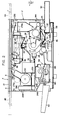
- the illustrated electrostatic copying apparatus has a substantially rectangular housing shown generally at 2.
- an original-support mechanism 4 for supporting an original document to be copied.
- the original-support mechanism 4 is constructed of a support frame 6 mounted movably for scanning of the original document by a suitable method (in the left and right directions in Figure 2), a transparent plate 8 ( Figure 2) fixed to the support frame 6 and adapted to place the original document thereon, and an original-holding member 10 which has one edge portion (the edge portion located in the upper part in Figure 1) connected pivotably to the support frame 6 and which is to be turned by a manual operation between a closed position at which it covers the transparent plate 3 and the original document placed on it (the position shown in Figures 1 and 2) and an open position at which the transparent plate 8 and the original document on it are brought to view.
- the original-support mechanism 4 is preferably of such a type that when the electrostatic copying apparatus is in an inoperative state, it stops at a stop position shown by a solid line in Figures 1 and 2, but when the copying apparatus sets in operation and the copying process is performed, it makes a preparatory movement from the stop position to a scanning movement starting position shown by a two-dot chain line 4A in Figure 2 in the right direction, then makes a scanning movement from this start position to a scanning movement-ending position shown by a two-dot chain line 4B in Figure 2 in the left direction, and thereafter, returns to the stop position in the right direction in Figure 2.
- operating elements such as a main switch, a knob for setting the number of copies required, and a knob for adjusting the intensity of exposure and display elements such as a display lamp, which are all known per se.
- a cylindrical rotary drum 12 is rotatably mounted within the housing 2, and a photosensitive member is disposed on at least a part of the peripheral surface of the rotary drum 12. Accordingly, the photosensitive member is moved by the rotation of the rotary drum 12 through a circular endless moving path defined by the peripheral surface of the rotary drum 12.
- an endless belt-like material known well to those skilled in the art may be mounted within the housing 2, and a photosensitive member may be disposed on at least a part of the surface of the endless belt-like member. In this alternative construction, the photosensitive member is moved through an endless moving path defined by the surface of the endless belt-like member.
- a latent electrostatic image-forming zone 16 Along the peripheral surface of the rotary drum 12 rotated in the direction of an arrow 14, therefore along the moving path of the photosensitive member on the rotary drum 12, are disposed a latent electrostatic image-forming zone 16, a developing zone 18 and a transfer zone 20 in this order viewed in the moving direction of the photosensitive member.
- a charging corona-discharge device 22 for applying corona discharge to the surface of the photosensitive member to charge it to a specified polarity.
- a developing device 24 is provided within.the developing zone 18, which function both as a developing means for applying toner particles to a latent electrostatic image formed on the photosensitive member to develop it and as a cleaning means for removing residual toner particles from the photosensitive member after the transfer of a developed image to a copying paper in the transfer zone 20 in the illustrated embodiment.
- the transfer zone 20 includes therein a transfer corona-discharge device 26 for applying corona discharge to the back surface of the copying paper at the time of transferring a developed image on the photosensitive member to the copying paper.
- a charge-eliminating corona-discharge device 28 and a charge-eliminating lamp 30 for removing residual charges on the photosensitive member after the transfer of a developed image on the photosensitive member to a copying paper in the transfer zone 20 are disposed downstream of the transfer zone 20 and upstream of the latent electrostatic image-forming zone 16 viewed in the rotating direction of the rotary drum 12 shown by the arrow 14, and therefore in the moving direction of the photosensitive member.
- the charge-eliminating corona-discharge device 28 applies corona discharge to the photosensitive member for charge elimination, and the charge-eliminating lamp 30 exposes the entire surface of the photosensitive member to light.
- An optical unit 32 for projecting the image of an original document placed on the transparent plate 8 of the original-support mechanism 4 onto the photosensitive member is provided above the rotary drum 12 within the housing 2.
- the optical unit 32 includes an illuminating lamp 36 for illuminating the original document through an exposure opening 34 formed on the top surface of the housing 2, and a first reflecting mirror 38, an in-mirror lens 40, a second reflecting mirror 42 and a third reflecting mirror 44 for projecting the light reflected from the original document onto the photosensitive member.
- the optical unit 32 pro projects the image of the original document placed on the transparent plate 8 onto the photosensitive member at a position immediately downstream of the charging corona-discharge device 22 in the rotating direction of the rotating drum 12 in the latent electrostatic image-forming zone 16.
- the image of the original document is scanned and optically projected on the photosensitive member by moving the original-support mechanism 4 in a scanning manner.
- the image of the original document can also be scanned and optically projected on the photosensitive member by scanningly moving at least a part of the optical unit.
- a paper transfer unit shown generally at 46 is also provided in the illustrated electrostatic copying apparatus.
- the paper transfer unit 46 includes a paper-feed mechanism 54 consisting of a paper cassette 50 whose-end is inserted into a cassette-receiving section 48 within the housing 2 through an opening formed in the right end wall of the housing 2 and a paper feed roller 52 for feeding copying paper sheets one by one from the paper cassette 50 by being rotationally driven while being in engagement with the topmost sheet of a stack of paper sheets in the paper cassette 50 through an opening formed on the top surface of the paper cassette 50.
- the paper transfer unit 46 also comprises a pair of transfer rollers 55 for transferring the paper sheet delivered by the action of the paper feed roller 52 to the transfer zone 20 and a separator roller 56 for separating the copying paper adhering closely to the surface of the photosensitive member on the rotary drum 12 in the transfer zone 20 from the photosensitive member and carrying it away from the transfer zone 20.
- the copying paper carried away from the transfer zone 20 moves through a fixing mechanism shown generally at 58 for fixing the developed image on the copying paper and is discharged into a receiver tray 60 from a discharge opening formed in the left end wall of the housing 2.
- the paper transfer unit 46 is of the type provided with the paper feed mechanism 54 utilizing the paper cassette 50. In place of, or in addition to,.the paper feed mechanism 54, a paper feed mechanism of the type adapted to unwind a roll of copying paper, cut it to a required length and deliver it may be provided in the paper transfer unit 46.
- the operation of the electrostatic copying apparatus described above is described briefly. While the rotary drum 12 is being rotated in the direction of the arrow 14, a latent electrostatic image is formed on the surface of the photosensitive member in the latent electrostatic image-forming zone 16. Specifically, the latent electrostatic image is forned by applying corona discharge to the photosensitive member by means of the charging corona-discharge device 22 a to charge it to a specified polarity, and then projecting the image of an original document placed on the transparent plate 8 onto the charged photosensitive member by means of the optical unit 32.
- the original-support mechanism 4 In projecting the image of the original document onto the photosensitive member by the optical unit 32, the original-support mechanism 4 is caused to make a scanning movement from the scanning movement starting position shown by the two-dot chain line 4A to the scanning movement ending position shown by the two-dot chain line 4B in the left direction in Figure 2. Then, in the developing zone 18, toner particles are applied to the latent electrostatic image on the photosensitive member by the action of the developing device 24 thereby developing the latent electrostatic image on the photosensitive member.
- the paper transfer unit 46 transfers a copying paper to the transfer zone 20 in synchronism with the rotation of the rotary drum 12, and in the transfer zone 20, the developed image on the photosensitive member is transferred to the copying paper.
- the copying paper having the developed image transferred thereto is fixed by the fixing mechanism 58 and then discharged into the receiver tray 60.
- the rotary drum 12 continues to rotate through at least one turn, preferably through two or more turns, after the developed image on the photosensitive member has been transferred to the copying paper, and during this period, the residual charge on the photosensitive member is removed by the action of the charge-eliminating corona-discharge device 28 and the charge-eliminating lamp 30. Furthermore, by the functioning of the developing device 24 as a cleaning means, the residual toner on the photosensitive member is removed.
- a pair of guide and support members 62 are provided within the housing 2 (see Figures 1 and 2) which are spaced from each other at a fixed distance in the direction of the central axis of rotation of the rotary drum 12 (i.e., in the direction perpendicular to the sheet surface in Figure 2), and the rotary drum 12 is rotatably mounted by utilizing the guide and support members 62.
- the illustrated rotary drum 12 is constructed of a shaft 64, bearing members 66 (only one of them is shown in Figure 3) having a relatively small diameter and a circular peripheral surface which are provided at the two opposite end portions of the shaft 64, and a drum member 68 fixed to the shaft 64 between the bearing members 66.
- a photosensitive member 70 made of a suitable material is disposed on the main surface portion of the drum member 68.
- annular groove 72 having a slightly smaller diameter than the outside diameter of the photosensitive member 70 is formed at the outside p or- tion of at least one side edge of the photosensitive member 70 on the drum member 68, and a non-photosensitive area 74 (an area where the photosensitive member does not exist) is formed at both end portions of the drum member 68.
- the tip of a peeling member known to those skilled in the art for accurately peeling a copying paper in contact with the surface of the photosensitive member 70 in the transfer zone 20 (at least one side edge portion of this copying paper is located in a mating position with respect to the annular groove 72) from the surface of the photosensitive member 70 after the developed image has been transferred to the copying paper.
- Each of the guide and support members 62 has a shaft support opening 76 for receiving each of the bearing members 66 located at the opposite end portions of the rotary drum 12. It is important that the shaft support opening 76 should have a recess 78 opened in a suitable direction (in the illustrated embodiment, in a right-hand side, substantially horizontal direction in Figure 2) substantially perpendicular to the central axis of rotation of the rotary drum 12.
- each of the guide and support members 62 has provided therein a main guide surface 80 which extends from the lower end of the recess 78 in a direction substantially perpendicular to the central axis of rotation of the rotary drum 12 and when mounting the rotary drum 12, guides the peripheral surface of the bearing member 66,
- the main guide surface 80 is defined by the top surface of the piece forming the guide and support member 62, and extends from the lower end of the recess 78 substantially horizontally and then inclines slightly downwardly.
- each of the guide and support members 62 has provided therein an initial guide surface 82 which extends inwardly of the main guide surface 80 in a direction substantially perpendicular to the central axis of rotation of the rotary drum 12 and when mounting the rotary drum 12, guides the non-photosensitive area 74 at each side end portion of the drum member 68 prior to the guiding of the peripheral surface of the bearing member 66 by the main guide surface 80.
- the initial guide surface 82 extends nearly horizontally inwardly and downwardly of the main guide surface 80.
- the rotary drum 12 is to be mounted on the guide and support members 62 in the following manner. With reference to Figure 2 as well as Figures 3 and 4, it is necessary that in mounting the rotary drum 12, the developing device 24 and the right end wall of the housing 2 should not be mounted in position but detached therefrom. In this condition, the rotary drum i2 is inserted into the housing 2 through an opening which is to be later closed by the right end wall, i.e. the right end opening of the housing 2, and the non-photosensitive areas 74 at the opposite end portions of the rotary drum 12 are placed respectively on the end portions of the initial guide surfaces 82 of the guide and support members 62.
- the rotary drum 12 is moved along the initial guide surfaces 82 toward the shaft support openings 76 of the rotary drum 12 (namely, to the left in Figure 2). In other words, the rotary drum 12 is revolved over the initial guide surfaces 82 toward the shaft support openings 76.
- the bearing members 66 on the opposite end portions of the rotary drum 12 respectively reach the main guide surfaces SO of the guide and support members 62.
- the rotary drum 12 is rotatably and detachably fitted into the shaft support openings 76 through the bearing members 66 disposed on its opposite end nortions.
- the developing device 24 has a frame generally shown at 84, and it is important that both side plates 86 of the frame (only one of them is shown in Figure 3) should be positioned face to face with the bearing members 66 disposed on the opposite end portions of the rotary drum 12 and should also have protruding pieces 88 protruding toward the bearing members 66.
- the develoning device 24 having the frame 84 described above is positioned in place by placing the lower ends of its both side portions on the initial guide surfaces 82 of the guide and support members 62 and then moving them toward the rotary drum 12 thereby pushing the' protruding pieces 88 against the peripheral surfaces of the bearing members 66 of the rotary drum 12. After it has been positioned in place, it is fixed at the position by, for example, fixing connecting pieces 90 secured to the roar sides of the both side portions of the frame 34 to suitable members within the housing 2, for example upstanding walls (not shown) disposed within the housing. 2.
- the apparatus is constructed such that when the protruding pieces 88 come into engagement with the bearing members 66, the distance between a cylindrical rotary sleeve provided in the frame 84 of the developing device 24 and the peripheral surface of the rotary drum 12 (i.e., the surface of the photosensitive member 70)-can be set as required. As is well known to those skilled in the art, to achieve good development as desired, it is important to set this distance as required.
- spacer rings rotatably and coaxially disposed at both end portions of the cylindricaly rotary sleeve of the developing device are caused to abut the non-photosensitive areas at both end portions of the drum member of the rotary drum, thereby holding the rotary drum in position and setting the distance between the peripheral surface of the rotary drum (i.e., the surface of the photosensitive member) and the rotary sleeve as required. It is necessary in this case to make precisely to required sizes the spacer rings which come into engagement with the drum member rotationally driven and are thereforemrotated according to the rotation of the drum member. It is comparatively difficult however to make such spacer rings precisely to required sizes, and expensive machining is required.
- the developing device 24 is provided with the frame 84 described hereinabove.
- the lower part of the frame 84 constitutes a developer recentacle 94 containing a developer 92 which in the illustrated embodiment is a two-component developer composed of carrier particles and toner particles.
- a developer applicator mechanism 96 and rotating and stirring mechanism 9Sa and 98b are disposed within the frame 84 of the developing device 24 .
- a toner particle dispenser generally shown at 100 is mounted to an onening portion formed on the top surface of the frame 84.
- the developer applicator mechanism 96 consists of a cylindrical rotary sleeve member 104 to be rotationally driven in the direction shown by arrow 102 ( Figure 5) and a roll-like stationary permanent magnet .106 disposed within the rotary sleeve member 104.
- the developer applicator mechanism 96 magnetically holds a part of the developer 92 in the receptacle 94 on the surface of the rotary sleeve member 104 in a developer take-up area 108 by the action of a magnetic field generated by the stationary permanent magnet 106 and carries the developer 92 so held to a developing operation area 110 within the developing zone 18 ( Figure 2) by the rotation of the rotary sleeve member 104.
- the developer applicator mechanism 96 magnetically holds a part of the developer 92 in the receptacle 94 on the surface of the rotary sleeve member 104 in a developer take-up area 108 by the action of a magnetic field generated by the stationary permanent magnet 106 and carries
- the developer 92 held on the surface of the rotary sleeve member 104 is brought into contact with the photosensitive member 70 ( Figure 3) on the rotary drum 12 being rotated in the direction of arrow 14 through an opening 111 formed in the front surface (i.e., that surface which faces the surface of the rotary drum 12) of the frame 84.
- the toner particles in the developer 92 are applied to the photosensitive member 70 to develop a latent electrostatic image formed on the photosensitive member 70 to a visible image (toner image) (when the developer device 24 performs a developing action). Or when the developing device 24 .
- the toner particles remaining on the photosensitive member 70 are removed from it and held on the rotary sleeve member 104 by the brushing action of the developer 92 held on the surface of the rotary sleeve member 104 against the photosensitive member 70 and by the magnetic attracting action of a magnetic field generated by the stationary permanent magnet 106.
- a brush length-setting member 112 for adjusting the amount of the developer 92, or the thickness of the layer of the developer 92, carried to the developing operation area 110 by the surface of the rotary sleeve member 104 to a suitable value.
- the tip portion of the brush length-setting member 112 is positioned a predetermined distance from the surface of the rotary sleeve member 104.
- the brush length-setting member 112 has an extension 112a which is curved so as to extend toward the surface. of the rotary drum 12 and of which free end is located in proximity to the surface of the rotary drum 12.
- the extension 112a prevents the developer 92, especially the toner particles in it, from scattering through a space between the frame 84 and the surface of the rotary drum 12,
- a scraping area 114 exists in which the developer 92 is scraped off from the surface of the rotary sleeve member 104. Because the stationary permanent magnet 106 is not magnetized at that part which corresponds to the scraping area 114, there is little or no magnetic field generated by the magnet 106 in the scraping area 114. Within the scraping area 114 is provided a scraping member l16 which contacts or approaches the surface of the rotary sleeve member 104 at its end. The developer 92 held on the surface of the.
- rotary sleeve member 104 is scraped off from the surface of the rotary sleeve member 104 in the scraping area 114 by the action of the end of the scraning member 116 on the developer 92 on the surface of the sleeve member 104. This scraping action is also assisted by the fact that there is little or no magnetic field generated in the scraping area 114.
- the scraped developer 92 flows down along the scraping member 116 and falls toward the stirring mechanism 98b.
- Each of the stirring mechanisms 98a and 98b is formed of a stirring vane member having a plate-like main vane 118a or 118b and a plurality of semi-helical auxiliary vanes 120a or 120b provided on both sides of the main vane 118a or 118b.
- the auxiliary vanes 120a of the stirring mechanism 98a are arranged alternately with the auxiliary vanes 120b of the stirring mechanism 98b so that the action of the stirring mechanism 98a and the action of the stirring mechanism 98b are supplemented each other.
- the stirring mechanisms 98a and 98b described above are rotated in the directions of arrows 122a and 122b respectively in Figure 5, whereby they stir un the developer 92 separated from the surface of the sleeve member 104 in the scraping area 114 and the toner particles supplied to the developer receptacle 94 from the toner particle dispenser 100 in mixture with the developer 92 present at the bottom portion of the receptacle 94 to mix the carrier particles and the toner particles in the developer 92 uniformly and charge the toner particles triboelectrically.
- the toner particle dispenser 100 is conprised- of a toner particle recentacle 124 and a dispenser roller 126.
- the receptacle 124 is defined by a front side wall 128, a rear side wall 130 and both end walls 132 (see Figure 7 also) and has a toner particle replenishing opening adapted to be closed by a detachableeclosure member 134 at its top portion, and a toner particle discharging onening at its bottom.
- the dispenser roller 126 having a plurality of grooves or depressions formed on its surface by knurling, etc.
- the dispenser roller 126 is disposed rotatably at the toner particle discharge opening, and is rotationally driven in the direction of an arrow 138 by an electric motor 136 mounted on one end wall of the receptacle 124.
- the dispenser roller 126 is rotated in the direction of the arrow 138, the toner particles 140 in the receptacle 124 are discharged as shown by an arrow 142 and dispensed to the develoner receptacle 94.
- the dispenser roller 126 is rotationally driven only for a required period of time during the performance of the copying process.
- the toner particle dispenser 100 dispenses a required amount of the toner particles 140 to the developer receptacle 94 every tine the copying process is performed.
- the toner p articles 140 in the receptacle 124 may become a bridge-like agglomerated nass riding between the front side wall 128 and the rear side wall 130 (so-called bridge phenomenon) and/or become an agglomerated mass above the dispenser roller 126.
- This tends to cause a so-called toner particle clogging phenomenon whereby the toner particles cannot be dispensed as required to the developer receptacle 94 from the receptacle 124 even when . the dispenser roller 126 is rotationally driven.
- both a known rotary toner stirring member 144 and a reciprocable slide plate 146 are provided within the receptacle 124 in the toner dispenser 100.
- the toner stiiring member 144 consisting of a shaft 148 extending above, and substantially parallel to, the dispenser roller 126 and stirrers 150 fixed to the shaft 148 in spaced-apart relationship in tne axial direction of the shaft 148 is rotatably mounted between the two end walls 132 of the receptacle 124.
- the slide plate 146 is disposed along the inside surface of at least one of the front side wall 128 and the rear side wall 130 (the rear side wall 130 in the illustrated embodiment) of the receptacle 124.
- the slide plate 146 At both end edges of the slide plate 146 disposed along at least the lower portion of the inside surface of the rear side wall 130, preferably along nearly the entire inside surface thereof, are provided coupling projections 152a and 152b, and holes formed in the coupling projections 152a and 152b are idly fitted over the shaft 143.
- the slide plate 146 is supported on the shaft 148 such that it can be moved freely in the axial direction of the shaft 148.
- An annular receiver plate 154 to be abutted against the outside surface of the coupling projection 152a is idly secured to one end portion of the shaft 148, and an annular receiver plate 156 is fixed to the shaft 148 outwardly of the annular receiver plate 154.
- a spring 160 for elastically biasing the slide plate 146 in the direction of an arrow 158 with respect to the shaft 148.
- a can member 162 located outwardly of the coupling projection 152b is fixed to the shaft 148.
- the cam member 162 has a cam surface 164 acting on the outside surface of the coupling projection 152b.
- the other end portion of the shaft 148 projects through the end wall 132 of the receptacle 124 and a gear 166 is fixed to the projecting end.
- the gear 166 is engaged with a gear 168 fixed to the output shaft of the electric motor 136 and also with a gear 170 fixedly secured to one end of the supporting shaft for the dispenser roller 126.
- the output shaft of the electric motor 136 is rotated in the direction of an arrow 172 in Figure 8 to rotate the dispenser roller 126 in the direction of an arrow 138 and simultaneously to rotate the toner stirring member 144 in the direction of an arrow 174.
- the cam member 162 fixed to the shaft 148 is rotated accompanyingly in the direction of an arrow 174.
- Rotation of the cam member 162 in the direction of arrow 174 causes the cam surface 164 to act on the coupling projection 152b, thereby moving the slide plate 146 in the direction of an arrow 176 against the elastic biasing action of the spring 160.
- the action of the rotating toner stirring member 144 prevents the toner particles 140 from becoming an agglomerated mass above the dispenser roller 126 and the action of the reciprocating slide plate 146 exactly prevents the toner particles 140 from becoming a bridge-like agglomerated mass between the front side wall 128 and the rear side wall 130 of the receptacle 124. Hence, the toner particle clogging phenomenon can be accurately prevented.
- a suitable projecting piece may, if desired, be attached to the inside surface of the slide plate 146.
- a switch mechanism 178 for detecting the amount of the developer 92 in the developer receptacle 94 within the frame 84 of the developing device 24.
- the switch mechanism 178 is electrically connected to an electrical contrcl circuit (not shown) which constitutes a developer detecting means for producing a signal of prohibiting supplying of toner particles when a sufficient amount of the developer 92 is present in the developer receptacle 94 and a toner supply hampering means which hampers the starting of the rotation of the dispenser roller 126 (therefore, the starting of the operation of the electric motor 136) while the aforesaid signal of prohibiting supplying of toner particles is being produced.
- the fixing mechanism shown generally at 58 has a lower frame 180 and an upper frame 182.
- the lower frame 180 is slidably mounted on a pair of support rails 184 ( Figure 2) extending in a direction perpendicular to the sheet surface in Figure 2.
- the upper frame 182 is mounted for pivoting with respect to a shaft 188 extending between the two end walls 186 of the lower frame 180, and therefore with respect to the lower frame 180.
- the upper frame 182 is at an operating position at which one side edge portion 192 of its top surface wall 190 abuts a receiver piece 194 extending inwardly from the top end portions of the two end walls 186 of the lower frame 180, i.e. the operating position shown by a solid line in Figures 9 and 10, and is held at the operating position by means of a setscrew 196 which extends through the one side edge portion 192 and is threadably fitted with the receiver piece 194.
- a hollow cylindrical fixing roller 200 Between two end walls 198 of the upper frame 182 is rotatably mounted a hollow cylindrical fixing roller 200, and a heater 202 composed of electrical resistance wires extending through the fixing roller 200 is fixed in place between the two end walls 198 of the upper frame 182. Furthermore, shaft support recesses 204 are formed at both end walls 193, and a shaft 208 having a paper t transfer roller 20G fixed thereto is rotatably mounted on the shaft support recesses 204.
- a shaft support lever 212 is pivotably mounted on the inside surface of each of the two end walls 186 of the lower frame 180 by means of a pin 210.
- a shaft support recess 214 is formed in the lever 212, and a support shaft 218 of a fixing roller 216 cooperating with the fixing roller 200 is mounted rotatably on the shaft support recess 214.
- a spring 220 which elastically biases the shaft support lever 212 counterclockwise in Figure 10 and thus elastically urges the fixing roller 216 against the fixing roller 200.
- a paper transfer roller 222 cooperating with the paper transfer roller 206 is fixed to the shaft 188 mounted rotatably between the two end walls 186 of the lower frame 180.
- the fixing rollers 200 and 216. are rotationally driven in the direction shown by an arrow 223, and the paper transfer rollers 206 and 222, in the direction shown by an arrow 225.
- a current is supplied to the heater 202 and thus the fixing roller 200 is heated.
- a copying paper having a developed image transferred thereto from the photosensitive member 70 ( Figure 3) in the transfer zone 20 ( Figure 2) is supplied between the fixing rollers 200 and 216 from right in Figure 10.
- the developed image on the copying paper is fixed under pressure by the pressure between the two fixing rollers 200 and 216, and simultaneously, the developed image on the copying paper is thermally fixed by the heat transmitted from the heater 202 to the copying paper via the fixing roller 200.
- the copying paper which has thus undergone the fixing action of the fixing rollers 200 and 216 is sent between the paper transfer rollers 206 and 222, and discharged onto the receiver tray 60 ( Figure 2) by the transferring action of the paper transfer rollers 206 and 222.
- a suitable coating such as a tetrafluoroethylene or silicone resin
- a peeling member 224 having a knife-like edge in proximity to the surface of the fixing roller 200.
- any paper jamming which may occur particularly at the sites of the fixing rollers 200 and 216 can be very easily eliminated.
- the first thing to do is to open the front wall of the housing 2 and move the lower frame 180 in a direction perpendicular to the sheet surface in Figure 2 along the support rails 184 ( Figure 2) thereby to draw out the entire fixing mechanism 58 from the housing 2.
- the setscrew 196 connecting the upper frame 182 to the lower frame 180 is removed, and the upper frame 182 is caused to pivot in the direction shown by an arrow 226 in Figure 10 to bring it to the position shown by a two-dot chain line in Figure 10.
- the inside of the fixing mechanism 58 is opened, and the copying paper jammed therein can be very easily removed.
- the above operation is carried out in the reverse order to return the fixing mechanism 58 to the required operating position.
- a partitioning wall 228 is provided in that portion of the housing 2 which is at the left of the rotary drum 12.
- the partitioning wall 228 divides the inside space of the housing 2 into an upper portion in which the optical unit 32 is located and a lower portion in which the paper transfer system 46 and the fixing mechanism 58 are located.
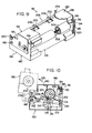
- a first fan 230 for cooling which is the same as in conventional electrostatic copying machines is disposed above the partitioning wall 228 in the vicinity of the left end portion of the housing 2.
- the first fan 230 composed of a silocco-type fan is drivingly connected to a main electric motor 232 disposed rearwarly thereof, for example, by being directly coupled to the output shaft of the motor 232.
- the main electric motor 232 like main electric motors in conventional electrostatic copy- ingmachines, is drivingly connected to driving elements (not shown) for the rotary drum 12, the original-support mechanism 4, the paper transfer unit 46, etc.
- the first fan 230 is rotationally driven thereby to suck the air from vents 234 formed in the left end wall of the housing 2, send the air to a passageway 236, allow it to pass through the optical unit 32, particularly, the vicinity of the original-illuminating lamp 36, thereby cooling it and discharge it from vents 238 formed at the upper portion of the right end wall of the housing 2 (or vents formed in the top surface wall of the housing 2).
- the above construction of the cooling system is also included in conventional electrostatic copying machines and is already known.
- the cooling system in. the conventional electrostatic copying machnies includes only the construction of the first fan 230, it has the following problems or defects.
- the fixing mechanism 58 is of the aforesaid type having electrical heater 202 ( Figures 9 and 10)
- the heat released from the heater 202 is trans- mitted to the photosensitive member 70 ( Figure 3) on the rotary drum 12 and is likely to deteriorate the photosensitive member 70. It is strongly desired therefore to prevent the heat of the heater 202 exactly from being transmitted to the photosensitive member 70.
- the heat from the heater 202 cannot sufficiently be prevented from being transmitted to the photosensitive member 70 only by the air flow . generated by the action of the first fan 230 described above.
- the reason for this is as follows: It is well known to those skilled in the art that the main electric motor 232 to which the first fan 230 is drivingly connected is energized generally at the time of starting the copying process by depression of a copying start switch following closing of the main switch of the electrostatic copying apparatus. Thus, the first fan 230 is actuated for the first tine at the start of the copying process.
- a current is generally supplied to the heater 202 of the fixing mechanism 58 as soon as the main switch is closed, because the fixing roller 200 needs to be heated to the required temperature by the time the fixing operation of the fixing mechanism is actually carried out. Accordingly, during the time from the closing of the main switch to the starting of the copying process and during the time from the ending of the copying process to the opening of the main switch, the first fan 230 is in the inoperative state but the heater 202 is in the electrified state. During such times, the heat released from the heater 202 is likely to be transmitted to the photosensitive member 70 to degrade it.
- the cooling system also includes a second fan 240 capable of acting independently from the first fan 230, in order to solve or remove the aforesaid problems or defects.
- the second fan 240 composed of an axial flow-type fan is disposed rearwardly of the first fan 230 and on the left side of the main electric motor 232 as can be understood from Figures 2 and 11.
- the second fan 240 is located bridging both the upper and lower portions of the housing 2 defined by the partitioning wall 228, so that it can act both on the upper and lower portions of the housing 2.
- An auxiliary electric motor 242 separate from the main electric motor 232, is associated with the second fan 240.
- the auxiliary electric motor 242 is energized upon the closing of the main switch of the electrostatic copying apparatus, and is maintained in the energized state until the main switch is open. Accordingly, the second fan 240 operates upon the closing of the main switch and continues to operate until the main switch is opened.
- the second 'fan 240 when the second 'fan 240 is actuated by the closing of the main switch, it sucks air from the vents 238 formed in the upper portion of the right end wall of the housing 2 (or vents formed in the top surface wall of the housing 2) and discharges the air from the vents 234 formed in the left end wall of the housing 2 through the upper portion of the housing 2, thereby effectively discharging the heat which may stay in the upper portion of the housing 2 during the time from the closing of the main switch to the energization of the main electric motor 232 and during the time from the deenergization of the main electric motor 232 to the opening of the main switch and also more effectively cooling the upper portion of the housing 2 in cooperation with the first fan 230 while the main electric motor 232 is being energized.
- the second fan 240 sucks the air from vents 244 formed in the lower part of the right end wall of the housing 2, passes the air through the lower portion of the housing 2, and therefore through the lower part of the rotary drum 12 and the vicinity of the fixing mechanism 58 and then through a passageway 248 defined between the partitioning wall 228 and a guide plate 246 beneath it, and discharges it from the vents 234 formed in the left end wall of the housing 2, thereby exactly preventing the heat of the heater 202 of the fixing mechanism 58 from being transmitted to the photosensitive member 70 ( Figure 3) on the rotary drum 12.
- the paper cassette 50 is mounted on the cassette-receiving section 48 of the paper transfer unit 46 mentioned hereinabove with reference to Figure 2, and in performing the copying process, a copying paper sheet of a predetermined size included in the cassette 50 is supplied to a paper transfer passage and a developed image corresponding to the image of an original document to be copied is formed on the copying paper sheet of the predetermined size.
- a developed image corresponding to the image of an original document to be copied on the surface of a copying paper of an arbitrary size, a master copying paper for utilization in offset printing, etc. instead of copying sheets of predetermined sizes (for example, B4, A4, and A5 according to JIS) stacked in the cassette 50.
- the apparatus of this invention is equipped with a manual paper-positioning mechanism mounted on the cassette-receiving section 48 in place of the paper cassette 50 and adapted to position a copying paper manually so that it can be fed to the copying paper transfer passage by the action of the paper feed roller 52 provided at the cassette-receiving section 48.
- the manual paper-positioning mechanism shown generally at.250 includes a frame 252. At least a front end portion of the frame 252 has a contour similar to the front end portion of the paper cassette 50 so that it can be inserted into the cassette-receiving section 48 of the housing 2 and mounted in position instead of the paper cassette 50 ( Figure 2).
- the top surface of the frame 252 defines a preferably flat guiding top surface 254 for guiding a copying paper to be positioned as required by a mannual operation (namely, in such a manner that the paper may be fed into the paper transfer passage by the action of the paper feed roller 52).
- a protruding piece 256 whose inside surface defines an upstanding guide surface for guiding one edge of at least a front end portion of a copying paper to be positioned manually as required.
- At least one (two in the drawings) opening 258 is formed in the top surface of the frame 252 which defines the guiding top surface 254.
- a shaft 260 is rotatably mounted to the front end portion of the frame 252, and an auxiliary roller 262 is fixed to the shaft 260 with the upper portion of its peripheral surface projecting upward through the opening 258.
- the manual paper-positioning mechanism 250 described above is mounted on the cassette-receiving section 48 of the housing 2 as shown in Figure 13 instead of the paper cassette 50 ( Figure 2).
- the peripheral surfaces of the auxiliary rollers 262 of the manual paper-positioning mechanism 250 come into engagement with the peripheral surface of the paper feed roller 52 disposed at the cassette-receiving section 48.
- the manual paper-positioning mechanism 250 After the manual paper-positioning mechanism 250 has been mounted as required to the cassette-receiving section 48, it is only sufficient to advance manually the copying paper along the guiding top surface 254 and to cause its leading end to be nipped between the paper feed roller 52 and the auxiliary rollers 262.
- the copying process by the electrostatic copying apparatus is started and the paper feed roller 52 is caused to begin rotation in the direction of arrow 264 at a certain time, the copying paper located on the guiding top surface 254 is fed to the copying paper transfer passage by the action of the paper feed roller 52.
- the operations of various constituent elements of the electrostatic copying apparatus are controlled on the basis of the longitudinal size of a copying paper transferred through the transfer zone 20 by the transfer unit 46, particularly the size of a copying paper contained in the cassette 50 mounted to the cassette-receiving section 48 (therefore, the paper fed by the action of the feed roller 52 and transferred through the transfer zone 20).
- the illustrated electrostatic copying apparatus includes a paper size display means at the cassette 50 ( Figure 2) mounted to the cassette-receiving section 48, and a sensing means for sensing the paper size display means is provided in the cassette-receiving section 48.
- the paper size display means and the sensing means constitute means for detecting the size of paper.
- one of four types of paper cassettes 50 including copying paper sheets of sizes A5, B5, A4 and B4 according to JIS is selectively mounted to the cassette-receiving section 48 provided at the lower part of the right end portion of the housing 2, as shown in Figure 2. Since the illustrated electrostatic copying apparatus is constructed such that each of the various types of paper cassettes 50 can be mounted selectively to one cassette-receiving section 48, it is convenient that irrespective of the sizes of the copying papers in the cassettes, at least the front end portion of the cassettes are formed in the same contour so that they can be mounted as required in the same configuration substantially on the cassette-receiving section 48.
- the various copying paper cassettes 50 to be selectively mounted on the cassette-receiving section 48 are provided each with a paper size display means for displaying the size of papers accomodated therein.
- a paper size display means for displaying the size of papers accomodated therein.
- the paper size display means is described below when the electrostatic copying apparatus includes four types of cassettes (A5, B5, A4 and B4 sizes) as described above. Referring to Figures 14-A to 14-D, two display positions 266a and 266b are defined at predetermined parts of the front surface of each copying paper cassette 50. In the A5 paper cassette 50 (A5) shown in Figure 14-A, no magnet exists at either of the two display positions 266a and 266b.
- the sensing means for sensing the paper size display means described above is provided at the cassette-receiving section 48.
- the sensing means in the illustrated embodiment is comprised of reed switches 268a and 268b (only 268b is shown in Figures 2 and 13, and both are shown in the block diagrams to be described hereinbelow) which are located opposite to the display positions 266a and 266b respectively and are adapted to be closed by the action of a magnetic field which may be generated by the magnets at the display positions 266a and 266b.
- the illustrated electrostatic copying apparatus may also have the manual paper-positioning mechanism 250 mounted instead of the paper cassette 50.
- magnets 270a and 270b are disposed at the front surface of the frame 252 of the manual paper-positioning mechanism 250 at positions mating with the display nositions 266a and 266b. Accordingly, when the manual paper-positioning mechanism 250 is mounted to the cassette-receiving section 48, the reed switches 268a and 268b assume the same condition as when the B4 paper cassette 50 (B4) is mounted, namely the condition indicated by ''3" in the binary notation.
- the two display positions 266b are defined at the front surface of the cassette 50 and the two reed switches 268a and 268b are disposed at the cassette-receiving section 48.
- the two reed switches 268a and 268b are disposed at the cassette-receiving section 48.
- three or more display positions and reed switches can respectively be provided.
- other suitable combinations for example a combination of a protrusion and a limit switch, may also be used.
- scanning movement of the original-support mechanism 4 causes the image of an original document placed on the transparent plate 8 of the original-support mechanism 4 to be scanned and projected upon the photosensitive member 70 ( Figure 3).
- the operations of the various elements of the electrostatic copying apparatus are controlled on the basis of the movement of the original-support mechanism 4 (or instead of the movement of the original-support mechanism 4, movement of at least a part of the optical unit 32 when the electrostatic copying apparatus is of the type wherein by moving at least a part of the optical unit 32 instead of the original-support mechanism 4, the image of the original document on the transparent plate 8 of the original-support mechanism 4 is scanned and projected upon the photosensitive member 70) as well as the size of the copying paper as described above.
- the illustrated electrostatic copying apparatus uses the following construction for detecting the movement of the original-support mechanism 4 (or at least a part of the optical unit 32).
- the illustrated electrostatic copying apparatus includes a known chain mechanism 272 as a power transmitting element for drivingly connecting the original-support mechanism 4 to the main electric motor 232 ( Figure 11).
- the chain mechanism 272 consists of a pair of sprocket wheels 274a and 274b rotatably mounted in spaced-apart relationship in the moving direction of the original-support mechanism 4 and an endless chain 276 wrapped about the sprocket wheels 274a and 274b.
- a follower plate 280 extending perpendicularly downwardly is fixed to the support frame 6 of the original-support mechanism 4.
- the follower plate 280 is formed an elongated slot 282 which extends in the perpendicular direction along a length corresponding to the distance between the upper travelling section and the lower travelling section of the endless chain 276.
- a cam roller 284 mounted on, and adapted to move with, the endless chain 276 is engaged with the slot 282.
- the chain mechanism 272, the follower plate 280 and the can roller 284 are known elements, and the detailed structures and operations of these elements are described, for example, in Japanese Laid-Open Patent Publication No. 136336/1979, and a description thereof is therefore omitted in the present application. It is to be noted however that the follower plate 280 constitutes an actuating piece which acts on a pivoting piece to be described below.
- a mounting bracket 286 ( Figure 15) is disposed at a fixed position with respect to the moving path of the follower plate 280 whose lower nart constitutes an actuating piece.
- a pivoting piece 283 To the mounting bracket 286 are mounted a pivoting piece 283, two normally open switches 290 and 292 (as will be stated hereinbelow, the normally open switch 290 constitutes a normally open switch for lamp illumination used to turn on an illuminating lamp 36 of the optical unit 32, and the normally open switch 292, a normally open switch for initiation of actuation used to initate the oneration of the charging corona-discharge device 22, etc.), and a locking means 294.
- the pivoting piece 288 is pivotably mounted to the mounting bracket 286 by means of a pin 296.
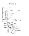
- the pivoting piece 288 is elastically biased to the inoperative position shown in Figures 15 and 16-A by the action of a suitable spring and a stop piece (not shown). But as will be described in detail below, it can be turned in the direction of arrow 298 by the lower portion (i.e., the actuating piece) of the follower plate 280 and brought to the operative position shown in Figures 16-C and 16-D.
- the locking means 294 composed of a lever- like member mounted pivotably to the bracket 286 by means of a pin 300 is normally biased elastically to the position shown in Figures 15, 16-A, 16-C and 16-D by.the action of a suitable spring and stop piece (not shown), but can be caused to pivot in the direction shown by an arrow 304 by the pivoting piece 288 and a lock releasing piece 302 secured to the endless chain 276 as will be described in detail hereinbelow.
- the detecting switch mechanism comprised of the actuating piece (the lower portion of the follower plate 280), the pivoting piece 288, the normally open switches 290 and 292, the locking means 294 and the lock releasing piece 302.
- the one edge and lower edge of the follower plate 280 act on the receiving portion 306 of the pivoting piece 288 to turn the pivoting piece 288 in the direction of an arrow 298 against the elastic biasing action of the spring (not shown), as can be understood from Figures 16-A to 16-B.
- a projection 308 formed on the pivoting piece 288 abuts the locking means 294 as shown in Figure 16-B thereby pivoting the locking means 294 in the direction shown by an arrow 304 against the elastic biasing action of a spring (not shown).
- the pivoting piece 288 is kept at the critical position illustrated in Figure 16-C by the locking action of the locking means 294 even when after the preparatory movement, the original-sunport mechanism 4 moves to the scanning movement-starting position shown by the two-dot chain line 4A in Figure 2 and further makes a scanning movement to the left in Figure 2 (to the right in Figures 16-A to 16-D) toward a scanning movement-ending position shown by the two-dot chain line 4B in Figure 2 thereby causing the follower plate 280 to depart from the pivoting piece 288.
- the lock releasing piece 302 mounted on the endless chain 276 of the chain mechanism 272 approaches the locking means 294 as shown in Figure 16-D.
- the lock releasing piece 302 acts on the locking means 294 to pivot the locking means 294 in the direction of an arrow 304 against the elastic biasing action of the spring (not shown).
- the recess 310 of the locking.means 294 comes out of engagement with the projection 308 . of the pivoting nephew 238, and therefore the locking action of the locking means 294 is released.
- the pivoting piece 288 is returned to the inoperative position, i.e.
- the pivoting piece 288 in its turning from the inoperative position shown in Figure 16-A to the critical position shown in Figure 16-C in the direction of the arrow 298, the pivoting piece 288 first closes the normally open switch 290, and then after some time interval, closes the normally open switch 292.
- the closed normally open switches 290 and 292 closed by the action of the pivoting piece 288 return to the open state when the pivoting piece 288 is returned to the inoperative position in the manner described above (therefore when the original-support mechanism 4 has made a scanning movement and approached or reached the scanning movement ending position shown by the two-dot chain line 4B in Figure 2).
- the illustrated electrostatic copying apparatus further includes the following construction in order to detect the movement of the original-support mechanism 4.
- the undersurface of the original-support mechanism 4 has provided thereon a plurality of actuators (first, second, third and fourth actuators 320a, 320b, 320c and 320d in the illustrated embodiment) at predetermined intervals in the moving direction of the original-support mechanism 4.
- a driven member 322 At a predetermined position within the housing 2 is disposed a driven member 322 which undergoes the action of the actuators 320a, 320b, 320c and 320d.
- the actuators 320a, 320b, 320c and 320d which can be formed of, for example, magnets successively act on the driven member 322 which can be formed, for example, of a reed switch when the original-support mechanism 4 makes a scanning movement from the scan movement-starting position shown by the two-dot chain line 4A to the right in Figure 17 to the scan movement-ending position shown by the two-dot chain line 4B.
- the driven member 322 produces a signal every tine it is acted upon by the actuators 320a, 320b, 320c and 320d successively.
- the first, second third and fourth actuators 320a, 320b, 320c and 320d and the driven member 322 are positioned in such a manner that the first actuator 320a acts on the driven member 322 when the original-support mechanism 4 makes a scanning movement from the sean movement-starting position shown by the two-dot chain line 4A by a distance corresponding to the longitudinal size of an A5-size copying sheet in accordance with JIS standards (the size of the copying paper in the moving direction, which paper is fed from the paper cassette 50); the second actuator 320b acts on it when the original-support mechanism 4 further makes scanning movement and advances by a distance corresponding to the longitudinal size of a BS-size copying paper in accordance with JIS standards from the scan movement-starting position; the third actuator 320c acts on it when the original-support mechanism 4 moves from the scan movement-starting position by a distance corresponding to the longitudinal size of an A4-size copying paper in accordance with JIS standards; and the fourth actuator
- FIG 18 is a block diagram showing in a simplified manner a part of a control electrical circuit used in the illuse trated electrostatic copying apparatus
- a visible paper size displaying means shown generally at 324 for performing visible display of the paper cassette 50 (see Figure 2) mounted to the cassette-receiving section 48 described above is connected to the reed switches 268a and 268b (see Figures 12 and 13) which constitute the sensing means in the paper size detecting means.
- the visible paper size displaying means 324 includes an A5-size displayer, a B5-size displayer, an A4-size displayer and a B4-size displayer (not shown) which may be composed of suitable lamps, for example, and an A5-size dis p layer energizing circuit 326 (A5), a B5-size displayer energizing circuit 326 (B5), an A4-size displayer energizing circuit 326 (A4) and a B4-size displayer energizing circuit 326 (B4) associated respectively with these displayers.
- A5-size dis p layer energizing circuit 326 A5-size dis p layer energizing circuit 326 (A5), a B5-size displayer energizing circuit 326 (B5), an A4-size displayer energizing circuit 326 (A4) and a B4-size displayer energizing circuit 326 (B4) associated respectively with these displayers.
- both of the reed switches 268a and 268b are closed by the mounting of the B-4 size paper cassette 50 (B4) shown in Figure 14-D to the cassette-receiving section 48.
- the B4-size displayer energizing circuit 326 (B4) is actuated whereby the B4-size displayer (not shown) visibly indicates that the B4-size paper cassette 50 (B4) is mounted to the cassette-receiving section 48.
- both the reed switches 268a and 268b are opend to actuate the A5-size displayer energizing circuit 326 (A5) whereby the A5-size displayer (not shown) visibly indicates that the A5-size paper cassette 50 (A5) is mounted to the cassette-receiving section 48.
- the read switch 268a is opened and the reed switch 268b is closed to actuate the A4-size displayer energizing circuit 326 (A4) whereby the A4-size displayer (not shown) visibly indicates that the A4-size paper cassette 50 (A4) is mounted to the cassette-receiving section 48.
- Figure 19 is a time chart showing the state of operation of various constituent elements of the illustrated electrostatic copying apparatus in conjunction with Figures 2 and 18, controlling of the operations of the original-illuminating lamp 36 of the optical unit 32, the charging corona-discharge device 22 and the transfer corona-discharge device 26. will be successively described.
- the original-illuminating lamp 36 of the optical unit 32 is turned on, as can be appreciated. from Figure 19. Since some period of time (the so-called rise time) is generally required from the lighting of the lamp to the time when the lamp is ready for performing the required operation, it is convenient to turn on the original illuminating lamp 36 a predetermined time before the original-support mechanism 4 starts to make a scanning movement from the scan movement starting position, namely before the scanning and exposing of an original document is started.
- the so-called rise time is generally required from the lighting of the lamp to the time when the lamp is ready for performing the required operation
- the actuation initiating means comprised of the normally open switch 292 and the timer 328 and capable of starting the actuation of the charging corona-discharge device 22 after the adjustable delay time dt from the closing of the normally - open switch 292 can be set or adjusted so that it starts the actuation of the charging corona-discharge device 22 simultaneously with, immediately before, or immediately after, the starting of the scanning movement of the original-support mechanism 4 and therefore the starting of the scanning and exposing of the original document. Conveniently, it is set or adjusted in the following manner with respect to a copying paper transferred from the cassette 50 mounted to the cassette-receiving section 48 through the transfer zone 20.
- the delay tine dt by the actuation starting means, especially the timer 328, such that the charging action of the corona discharge device 22 is started slightly upstream of that site of the photosensitive member 70 ( Figure 3) on the rotary drum 12 with which is mated in the transfer zone 20 the leading end of the copying paper which is transferred from the cassette 50 to the transfer zone 20 in synchronism with the scanning and exposing of the original document (or the rotation of the rotary drum 12) by means known to those skilled in the art.
- the time from the starting of the actuation of the charging corona-discharge device 22 to the starting of the actuation of the transfer corona-discharge device 26, i.e. the time t 1 defined by the actuation starting timer 334, can be set or adjusted so that it corresponds to the time required for a predetermined site on the photosensitive member 70 ( Figure 3) to move from a region where it undergoes the action of the charging corona-discharge device 22 to a region where it undergoes the action of the transfer corona-discharge device 26 by the rotation of the rotary drum 12.
- the actuators 320a, 320b, 320c and 320d provided on the original-support mechanism 4 successively act on the driven member 322 disposed in the housing 2, and the driven member 322 produces a pulse signal every time it is acted upon by the actuators 320a, 320b, 320c and 320d as shown in Figure 19.
- a first pulse signal is produced when the original-support mechanism 4 makes a scanning movement from the scanning movement starting position by a distance corresponding to the,longitudinal size of an A5-size copying paper.
- a second pulse signal is produced when it makes a scanning movement by a distance corresponding to the longitudinal size of a B5-size copying paper.
- a third pulse signal is produced.
- a fourth pulse signal is produced when the original-support mechanism 4 makes a scanning movement by a distance corresponding to the longitudinal size of a B4-size copying paper.
- the pulse signals produced by the driven member 322 are fed into the counter 330. Every time the counter 330 receives the pulse signal, its binary notation number read thereinto is decreased by one.
- the counter 330 When the counter 330 receives the pulse signal with the binary notation being “0”, it produces an output signal. Accordingly, when a signal supplied to the counter 330 from the reed switches 268a and 268b constituting the sensing means of the paner size detecting means is "0" in the binary notation (that is, when the A5-size paper cassette 50 (A5) is mounted to the cassette-receiving section 48), the counter 330 produces an output signal upon receipt of the first pulse signal.
- the counter 330 When a signal supplied to the counter 330 from the reed switches 268a and 268b is "1" in the binary notation [that is, when the B5-size paper cassette 50 (B5) is mounted to the cassette-receiving section 48], the counter 330 produces an output signal upon receipt of the second pulse signal subsequent to the first pulse signal.
- a signal supplied to the counter 330 from the reed switches 268a and 268b is "2" in the binary notation [that is, when the cassette A5-size paper cassette 50 (A4) is mounted to the cassette-receiving section 48]
- the counter 330 produces an output signal upon receipt of the third pulse signal subsequent to the first and second pulse signals.
- the time from the stopping of the actuation of the transfer corona discharge device 22 to the stopping of the actuation of the corona discharge device 26, that is the time t 2 defined by the a actuation stopping timer 338, can be set at or adjusted to a value substantially equal to, or slightly longer than, the time t 1 defined by the actuation starting timer 334.
- the original-illuminating lamp 36 turned on by the closing of the normally open switch 290 is turned off when the original-support mechanism 4 further makes a scanning movement and the lock releasing piece 302 ( Figure 16-D) acts on the locking means 294 to return the pivoting piece 288 to the inoperative position (i.e., the position shown in Figures 15 and 16-A) and bring the normally open switch 290 to the open - state.
- the lock releasing piece 302 Figure 16-D
- the charging corona discharge device 22 for charging purposes is actuated only for a period of time which corresponds to the longitudinal size of a copying paper which is contained in the cassette 50 set at the cassette-receiving section 48 and is transferred through the transfer zone 20.
- the longitudinal size (the size in the rotating direction of the rctary drum 12) of a latent electrostatic image formed on the photosensitive member 70 ( Figure 3) on the rotary drum 12 and of a visible image obtained by developing the latent electrostatic image correspond respect tively to the longitudinal size of the copying paper transferred through the transfer zone 20.
- the rotary drum 12 is rotated through two turns in each copying cycle (after rotating the rotary drum 12 through two turns in the final copying cycle, it is possible, if desired, to rotate the rotary drum 12 further through at least one turn, thereby excerting an additional action of removing the residual charge and toner particles).
- the charge-eliminating corona-discharge device 28 and the charge-eliminating lamp 30 to act once on the photosensitive member 70 and simultaneously to cause the developing device 24 to act once as a cleaning means. By causing these means to act only once, the residual charge and toner particles can be fully removed from the photosensitive member 70 after the transfer oneration.
- the illustrated electrostatic copying apparatus may also be constructed such that instead of the paper cassette 50, the manual paper-positioning mechanism 250 is mounted to the cassette-receiving section 48 to transfer a copying paper of an arbitrary size through the transfer zone 20.
- the sensing means in the paper size detecting means i.e. the reed switches 268a and 268b, produces the same paper size signal as it produces when the B4-size paper cassette 50 (B4) is mounted to the cassette-receiving section 48, and therefore, the charging corona-dischage device 22 is actuated only for a period of tine corresponding to the longitudinal size of a B4-size copying paper.
- a copying paper to be positioned by utilizing the manual paper-positioning mechanism 250 is smaller than the B4-size, the longitudinal size of a visible image formed on the photosensitive member 70 is larger than the longitudinal size of the copying paper, and it may therefore happen that a part of the visible image on the photosensitive member 70 will not be transferred to the copying paper but remain on the photosensitive member 70 after the trans- fcrring operation.
- the manual paper-positioning mechanism 250 is utilized, successive multiple copying cycles are intrinsically not performed. When one copying cycle is carried out at intermittent times, there is no particular inconvenience even when the rotary drum 12 is rotated through at least three turns for each copying cycle to remove the residual charge and toner particles on the photosensitive member 70 repeatedly. By this operation, the relatively large amounts of residual charges and toner particles can be fully removed.
- the transfer corona discharge device 26 is also actuated only for a period of time corresponding to the longitudinal size of a copying paper transferred through the transfer zone 20, and therefore it is possible to avoid any adverse e effect on the photosensitive mamber 70 of direct corona discharge which may be applied by the transfer corona discharge device 26 when no copying paper exists in the transfer zone 20.
- the illustrated electrostatic copying apparatus is of a so-called cassette paper feeding type wherein a sheet-like copying paper is fed from from the cassette 50 mounted to the cassette receiving section 43.
- the basic technical idea that the charging corona-discharge device 22 (and the transfer corona-discharge device 26) are actuated only for a period of time which correspond to the longitudinal size of a copying paper transferred through the transfer zone 20 can also be applied to an electrostatic copying apparatus of a so-called roll paper feeding type in which a roll-like copying paper is unwound, cut to the required size and transferred through the transfer zone 20. In this case, it is possible to detect the longitudinal size of the unwound and cut paper and to control the actuation of the charging corona discharge device 22 (and the transfer corona discharge device 26) according to the detected longitudinal size of the copying paper.
- the illustrated electrostatic copying apparatus is of the so-called visible image transfer type in which a latent electrostatic image formed on the photosensitive member 70 is developed and the developed image is transferred to a copying paper.
- the basic technical concept that the charging corona-discharge device 22 is actuated only for a period of time corresponding to the longitudinal size of a conying paper transferred through the transfer zone 20 can also be applied to an electrostatic copying apparatus of a so-called latent electrostatic image transfer type in which the latent electrostatic image formed on the photosensitive member 70 is transferred to a copying paner without development.
- the illustrated electrostatic copying apparatus is provided with the fixing mechanism 58 having the electric heater 202.
- the supply of an electric current to the heater 202 which is started by the closing of the main switch (not shown) of the electrostatic copying apparatus is generally controlled properly according to the temperature of the fixing mechanism 58 in order to maintain the temperature of the fixing mechanism 58 within a required range.
- this control is effected such that the current supply is interrupted when the temperature of the fixing mechanism 58 rises above a certain limit, and is resumed when the temperature of the fixing mechanism 58 decreases below the limit.
- the current is supplied in the alternating-current half-wave state when the temperature of the fixing mechanism 58 exceeds the limit, and is supplied in the alternating-current full-wave state when the temperature of the fixing mechanism 58 falls below the limit.
- ⁇ 7hen a change occurs in the state of a current supply to the heater 202 of the fixing mechanism 58 during the formation of a latent electrostatic image on the photosensitive member 70 or during the transfer of a visible image on the photosensitive member 70 to a conying paper
- the power supply source of the electrostatic copying apparatus undergoes influences and some variations occur in the operations of electrical elements such as the original-illuminating lamp 36 of the optical unit 32 or the charging corona-discharge device 22 and the transfer corona-discharge device 26. This is likely to result in non-uniformity in the formation of the latent electrostatic image or the transfer of the visible image.
- the apparatus of this invention in one aspect thereof, includes a current supply change inhibiting means which maintains the state of current supply to the heater 202 of the fixing mechanism 58 in a certain predetermined state while at least one of the corona discharge devices 22 and 26 is in operation and therefore from the starting of formation of the latent electrostatic image until the end of the transfer of the developed image.
- a signal is put into a temperature control means 340 which properly controls the state of current supply to the heater 202 of the fixing mechanism 58 according to the temperature of the fixing mechanism 58.
- This input signal causes the temperature control means 340 to interrupt current supply to the heater 202, and this state in maintained while the input signal exists.
- the temperature control means 340 may interrupt current supply to the heater 202 and be maintained in this state by the input signal, it is also possible, if desired, to cause the temperature control means 340 to continue current supply to the heater 202 (in the alternating-current full-wave state or the alternating-current half-wave state) and be maintained in this state by the input siqnal.
- the state of the temperature control means 340 at the time of production of the input signal may be maintained without particularly changing it.
- the illustrated electrostatic copying apparatus further includes a toner particle dispensing control means shown generally at 342 in Figure 18 which actuates the toner particle dispenser 100 in the developing apparatus 24 described with reference to Figures 5 to 8 only for a time period which corresponds to the longitudinal size of a copying paper transferred through the transfer zone 20 ( ( Figure 2).
- the toner particle dispensing control means 342 includes a counter 344, a first clock pulse oscillator 346, a second clock pulse oscillator 348 and a circuit 350 for energizing a toner particle dispensing electric motor (an electric motor shown at 136 in Figures 6 to' 8).
- the first clock pulse oscillator 346 and the second clock pulse oscillator 348 are connected to the counter 344 through a gate element controlled by a signal from the reed switch 268a.
- the period of the clock pulse generated by the first clock pulse oscillator 346 is set at the time required to dispense an amount of toner particles 140 which corresponds to the amount of toner particles 140 consumed in developing a latent electrostatic image according to a standard A5-size original document (that is, the time of rotation required for the paper feed roller 126 to dispense the aforesaid amount of toner particles 140 from the toner particle dispenser 100 to the developer receptacle 94 in the developing device 24 shown in Figures 5 to 8).
- the period of the clock pulse genrated by the second clock pulse oscillator 348 is set at the time required to dispense an amount of the toner particles 140 which corresponds to the amount of the toner particles 140 consumed in developing a latent electrostatic image according to a standard B5-size original document.
- the reed switch 263b is connected further to the counter 344.
- the reed switch 268b is open and therefore the A5-size paner cassette 50 (A5) shown in Figure 14-A or the B5-size paper cassette 50 (B5) is mounted to the cassette-receiving section 43 ( Figure 2), once the counter 344 is actuated as described below, it is maintained in the actuated state only for one period of the clock pulse fed from the first or second clock pulse oscillator 346 or 348.
- the counter 344 is set into operation, it is maintained in the actuated state for one period of the clock pulse generated by the first clock pulse oscillator 346 (therefore, for the time required to dispense an amount of the toner particles 140 which corresponds to the amount of the toner particles 140 consumed in developing a latent electrostatic image according to a standard A5-size original document) when the A5- size paper cassette 50 (A5) is mounted to the cassette-receiving section 48; for one period of the clock pulse generated by the second clock pulse oscillator 348 (therefore, for the time required to dispense an amount of the toner particles 140 which corresponds to the amount of the toner particles 140 consumed in developing a latent electrostatic image according to a standard B5- size original document) when the B5-size paper cassette 50 (B5) is mounted to the cassette-receiving section 48; for 2 periods of the clock pulse generated by the first clock pulse oscillator 346 (therefore, for the time required to
- the counter 344 shown in Figure 18 is started during the rise time of the clock pulse supplied from the first or second clock pulse oscillator 346 or 348 after the lapse of the delay time dt defined by the timer 328 (in the state shown in Figures 18 and 19, during the rise time of the clock pulse fed from the second clock pulse oscillator 348 because the B4-size paper cassette 50 (B4) is mounted) and is maintained in the actuated state for the period of time described hereinabove (for two periods of the clock pulse generated by the second clock pulse oscillator 348 in the state shown in Figures 18 and 19).
- the circuit 350 for energizing the electric motor for toner particle dispensing is maintained in the actuated state, and the electric motor 136 in the developing device 24 shown in Figures 5 to 8 is energized to rotationally drive the feed roller 126 for the period defined by the counter 344 and to dispense the toner particles 140 to the developer receptacle 94 from the receptacle 124 of the toner particle dispenser 100.
- an amount of the toner particles 140 which corresponds substantially to the size of a copying paper transferred through the transfer zone 20 ( Figure 2) and therefore the size of a latent electrostatic image formed on the photosensitive member 70 ( Figure 3), that is, the amount of the toner particles 140 consumed by the development, is dispensed to the develoner receptacle 94 every time the copying process is performed.
- the toner particles 140 are normally dispensed to the developer receptacle 94 from the receptacle 124 of the toner particle dispenser 100 by dint of the toner particle dispensing control means 342 ( Figure 18) every time the copying process is performed,
- the developing device 24 has the switch mechanism 178 for detecting the amount of the developer 92 within the develoner receptacle 94.
- a developer detecting means 352 ' ( Figure 20) consisting of an electrical circuit including the aforesaid switch mechanism 178 produces a signal of inhibiting dispensing of the toner particles 140 thereby to hamper the starting of the toner particle dispensing action by the control of the toner particle dispensing control means 342, namely the toner particle dispensing action according to the peformance of each copying cycle, and thereby to prevent the developer 92 in the developer receptacle 94 from becoming excessive (for the structure and operation of the switch mechanism 178 and related electrical circuits, see the specification and drawings of the above-cited Japanese Patent Application No. 22699/1980).
- the toner particle dispensing action according to the performance of each copying cycle is controlled such that the toner particles 140 are supplied in an amount which corresponds to the amount of the toner particles 140 consumed by the development of a latent electrostatic image in each copying cycle but which is slightly large than the standard amount of the toner particles 140 actually consumed. Thia accurately prevents the amount of the developer 92 within the developer receptacle 94 from decreasing excessively.
- the copying process is repeated through a certain number of cycles so long as the toner particle dispenser 100 is in condition to perform a normal toner dispensing action. Accordingly, when the toner dispensing action has been repeated a certain number of times, the aforesaid signal of hampering toner particle dispensing is necessarily produced.
- the dispensing action of the toner particle dispenser 100 becomes imperfect because, for example, of the extreme reduction of the amount of the toner particles 140 remaining in the receptacle 124, the toner particles 140 are not dispensed as required for each copying cycle even when the copying process is repeated through a predetermined number of cycles. Hence, the aforesaid signal of hampering the toner particle dispensing is not nroduced.
- the developing device 24 used in the illustrated electrostatic copying apparatus is provided with a warning means which informs the operator of the imperfect action of the toner particle dispenser 100 by producing a warning signal in the event that the developer detecting means 352 ( Figure 20) does not produce the signal of hampering the toner particle dispensing even when the copying process is repeated a predetermined number of times.
- the warning means shown generally at 354 is comprised of a circuit 356 for detecting the number of copying cycles by producing one pulse signal for each copying cycle and a counter 358 which receives and counts the pulse signals generated by the circuit 356.
- a circuit 356 for detecting the number of copying cycles by producing one pulse signal for each copying cycle
- a counter 358 which receives and counts the pulse signals generated by the circuit 356.
- To the counter 358 is connected the aforesaid developer detecting means 352, so that when the developer detecting means 352 produces the signal of hampering the toner particle dispensing, the counted value of the counter 358 will be cleared.
- the counter 358 itself is constructed such that it produces an output signal or a warning signal when it has counted an arbitrarily prescribed number (for example, 8).
- the developer detecting means 352 does not continuously produce the signal of hampering the toner dispensing (therefore, the counted value of the counter 358 is not cleared) despite the fact that the copying process has been repeated through a predetermined number of cycles, for example through eight cycles (therefore eight nulse signals have been fed to the counter 358 from the detecting circuit 356), the counted value of the counter 358 reaches 8 and the counter 358 produces a warning signal.
- the warning signal is fed to a warning display circuit 360 to actuate a warning lamp and/or a warning alarm, etc., thus informing the operator that the action of the toner dispenser 100 is imperfect and it should be corrected by, for example, supplying toner particles 140 to the receptacle 124.
- the electrostatic copying machine is generally equipped with a paper jamming detecting means for detecting paper jamming which may occur in a paper transfer. passage and producing a paper jamming signal, an emergency stop means for stopping the performance of the copying process by the electrostatic copying machine according to the paper jamming signal, and a manually onerable release switch which, after elimination of a jammed naner, is manually operated to release the action of the emergency stop means and enable the copying process to be resumed.
- a paper jamming detecting means for detecting paper jamming which may occur in a paper transfer. passage and producing a paper jamming signal
- an emergency stop means for stopping the performance of the copying process by the electrostatic copying machine according to the paper jamming signal
- a manually onerable release switch which, after elimination of a jammed naner, is manually operated to release the action of the emergency stop means and enable the copying process to be resumed.
- the illustrated electrostatic copying apparatus,too is provided with a paper jamming detecting means (not shown), an emergency stop means (not shown), and a manually operable release switch 362 ( Figure 21) which are of known structures.
- a conventional electrostatic copying apparatus is constructed such that when the aforesaid manually operable release switch is operated after elimination of a jammed paper, a normal copying process will be resumed without any special action being performed, the following problem arises. For example, when paper jamming occurs while a part of a developed visible image on the photosensitive member remains there without being transferred to a copying paper, the copying process of the copying apparatus is also stopped immediately by the actions of the aforesaid detecting means and emergency stop means, and therefore, the cooying process comes to an end while at least a part of the visible image remains on the photosensitive member.
- the apparatus of this invention in one aspect thereof, is provided with a preparatory driving means 364 which after eliminating paper jamming and releasing the stopping action of the emergency stop means (not shown) by operating the manually operable release switch 362 ( Figure 21), energizes the main electric motor 232 ( Figure ll) drivingly connected to the photosensitive member 70 ( Figure 3) thereby to move the photo- sensitive member 70 through at least one rotation.
- the preparatory driving means 364 is made up of a timer which upon closing of the release switch 362 by a manual operation, is actuated for a period of time required to rotate the rotary drum 12 having the photosensitive member 70 thereon through at least one turn, preferably 2 or more turns.
- the preparatory driving means 364 supplies a signal to a main electric motor-energizing circuit 366 and actuates it.
- the main electric motor-energizing circuit 366 When the main electric motor-energizing circuit 366 is actuated, the main electric motor 232 ( Figure 11) is energized thereby rotating the rotary drum 12 and actuating the developing device 24 which also functions as a cleaning means in the illustrated electrostatic copying apparatus.
- the charge-eliminating corona discharge device 28 and the charge-eliminating lamp 30 Figure 2 are also actuated.
- the action of the preparatory driving means 364 causes the rotary drum 12 to rotate through at least one turn, preferably two or more turns.
- the developing device 24 which also functions as a cleaning means and the charge-eliminating corona discharge device 28 and the charge- eliminating lamp 30 are actuated. Consequently, the residual charge and/or the toner particles on the photosensitive member 70 ( Figure 3) from the previous copying cycle interrupted by paper jamming can be fully removed prior to the performance of the next cycle of copying.
- electrostatic copying apparatus is of the so-called visible image transfer type, it will be evident that the aforesaid preparatory driving means 364 can .also be applied to electrostatic copying apparatus of the latent electrostatic image transfer type.
- an electrostatic copying apparatus comprising a housing, a photosensitive member disposed within the housing for free movement through an endless moving path defined within the housing, an original-support mechanism disposed on the top surface of the housing and including a transparent plate on which to place an original document to be copied, a charging corona-discharge device for applying corona discharge to the photosensitive member in a latent electrostatic image-forming zone.located along the moving path of the photosensitive member, an optical unit for projecting the image of the original document placed on the transparent plate onto the photosensitive member in the latent electrostatic image-forming zone, a copying paper transfer unit for transferring a.
- the apparatus further comprising a preparatory driving means which upon the releasing of the stopping action of the emergency stopping means by the operation of the release switch, energizes a main electric motor drivingly connected to the photosensitive member, thereby moving the photosensitive member through at least one rotation through said endless moving path.
- the preparatory driving means can comprise a timer which acts only for a predetermined period of time from the time of operation of the manually operable release switch.
- the apparatus can further comprise a developing device for developing a latent electrostatic image formed on the photosensitive member by applying toner particles thereto in a developing zone located along the moving path of the photosensitve member and, viewed in the moving direction of the photosensitive member, both downstream of the latent electrostatic image-forming zone and upstream.of the transfer zone, said developing device including a magnetic brush-type developer applicator mechanism having a cylindrical rotary sleeve drivingly connected to the main electric motor and a magnet disposed within the sleeve, the rotary sleeve being adapted to hold.
- the developing device also performs a cleaning action of removing toner particles remaining on the photosensitive member after a developed visible image formed on the photosensitive member has been transferred to the copying paper in t.he transfer zone.
- an electrostatic copying apparatus comprising a housing, a rotary drum mounted rotatably within the housing and having a photosensitive member said rotary drum including a shaft, bearing members having a circular peripheral surface and mounted on two opposite ends of the shaft and a drum member fixed to the shaft between the bearing members and having the photosensitive member on at least a part of its peripheral surface, an original-support mechanism disposed on the top surface of the housing and including a transparent plate.on which to place an original document to be copied, a charging corona-discharge device for applying corona discharge to the photosensitive member in a latent electrostatic image-forming zone located along the peripheral surface of the rotary drum, an optical unit for projecting the image of the original document placed on the transparent plate onto the photosensitive member in the latent electrostatic image-forming zone, a developing device for developing a latent electrostatic image formed on the photosensitive member by applying toner particles thereto in a developing zone located along the moving path of the photosensitive member and,
- a non-photosensitive area without the photosensitive member can exist at both side end portions of the drum member of the rotary drum, and each of the guide and support members can have formed therein an initial guide surface extending inwardly of the main guide surface and substantially perpendicularly to the central axis of rotation of the rotary drum, so'that when each non-photosensitive area of the drum member is moved along the respective initial guide surface, each of the bearing members is positioned on the main guide surface.
- the frame of the developing device can be positioned in place within the housing by causing the free end of each projecting piece of the two side plates to abut the peripheral surface of each of the bearings positioned in the shaft support openings and placing a part of the lower ends of the two side portions of the frame on the initial guide surface.
- a developing device for an electrostatic copying apparatus comprising a developer receptacle, a developer applicator mechanism for holding a part of a developer in the receptacle on its surface and applying toner particles to a latent electrostatic image to be developed, and a toner particle dispenser mechanism, said toner particle dispenser having a toner particle receptacle with an open bottom and a feed roller disposed rotatably at the opening of the toner particle receptacle and .
- a slide plate capable of reciprocating in the widthwise direction along the inner surface of at least one side wall of the toner particle receptacle is mounted to at least the lower portion of the inner surface of said side wall.
- the sliding plate can be drivingly connected to the feed roller and be adapted to reciprocate when the feed roller is rotationally driven.
- the toner particle receptacle can have rotatably mounted therein a toner particle stirring member extending above, and substantially parallel to the feed roller, and the slide plate can be drivingly connected to the feed roller via the toner particle stirring member so that when the-feed roller is rotationally driven, the toner particle stirring member being rotated and simultaneously the sliding plate being caused to reciprocate.
- the apparatus can also include a feed roller rotation controlling means for rotationally driving the feed roller according to the copying process by the electrostatic copying apparatus, a developer means for detecting the amount of the developer present in the developer receptacle and when a sufficient amount of the developer exists in the receptacle, producing a signal for prohibiting the dispensing of the toner particles, a toner particle dispensing hampering means for hampering the starting of the rotation of the feed roller by the feed roller rotation controlling means while the signal for prohibiting the dispensing of the toner particles is produced, and a warning means 'which when the developer detecting means does not continuously produce the signal of prohibiting the dispensing of the toner particles during repeated performance of the copying process through a predetermined number of cycles, produces a warning signal indicating that the dispensing of toner particles from the toner receptacle to the developer receptacle is imperfect.
- a feed roller rotation controlling means for rotationally driving the feed roller according to the copying process by the electrostatic copying apparatus
- the developer present in the developer receptacle is preferably a two-component developer composed of magnetic carrier particles and toner particles.
- an electrostatic copying apparatus comprising a housing, a rotary drum mounted rotatably within the housing and having a photosensitive member on at least a part of its peripheral surface, an original-support mechanism disposed on the top surface of the housing and including a transparent plate on which to place an original document to be copied, a charging corona-discharge device for applying corona discharge to the photosensitive member in a latent electrostatic image-forming zone - located along the peripheral surface of the rotary drum, an optical unit disposed above the rotary drum within the housing for projecting the image of the original document placed on the transparent plate onto the photosensitive member in the latent electrostatic image-forming zone, a copying paper transfer unit for transferring a copying paper through a transfer passage which extends from one end portion of the housing to its other end in the lower portion of the housing through a transfer zone located below the rotary drum, along the peripheral surface of the rotary drum and downstream of the latent electrostatic image-forming zone viewed in the rotating
- the first fan can be a silocco-type fan for discharging air sucked from said other end of the housing out of the housing through said upper portion, and the-second fan can be an axial-flow type fan.
- a mechanism for positioning a copying paper manually said positioning mechanism being applied to an electrostatic copying apparatus
- a copying paper transfer unit comprising a paper feed mechanism comprised of a cassette-receiving section formed at one end portion of a housing of the electrostatic copying apparatus for detachably receiving a box-like copying paper cassette having at least a part of its top surface opened and including a plurality of copying paper sheets of predetermined size in the stacked state and at least one paper feed roller which is mounted rotatably to an upper portion of the cassette-receiving section and which comes into engagement with the topmost copying paper in the stacked copying paper sheets in the copying paper cassette through said opening of the copying paper cassette mounted .to the cassette-receiving section and.
- said manually positioning mechanism being capable of positioning an arbitrary copying paper with respect to the feed roller by a manual operation so that the copying paper is fed by the rotation of the feed roller, instead of mounting the .copying paper cassette to the cassette-receiving section and automatically feeding the copying paper sheet in the copying paper cassette
- said manually positioning mechanism including a frame capable of being detachably mounted to the cassette-receiving section and having a guide top surface with at least one opening and at least one auxiliary roller mounted rotatably on the frame with the upper portion of its peripheral surface protruding upwardly through and past said opening, whereby when the frame is mounted as prescribed to the cassette-receiving section, the upper portion of the peripheral surface of the auxiliary roller comes into engagement with the peripheral surface of the paper feed roller, and when in this state, the copying paper is advanced manually over the guide top surface of the frame, its leading end is nipped by the paper feed roller and the auxiliary roller.
- An upstanding guiding inside surface for guiding one edge of at least the leading end of the copying paper can be formed at least in the front end of one edge portion of the guiding top surface.
Landscapes
- Physics & Mathematics (AREA)
- General Physics & Mathematics (AREA)
- Engineering & Computer Science (AREA)
- Environmental Sciences (AREA)
- Microelectronics & Electronic Packaging (AREA)
- Biodiversity & Conservation Biology (AREA)
- Ecology (AREA)
- Environmental & Geological Engineering (AREA)
- Life Sciences & Earth Sciences (AREA)
- Plasma & Fusion (AREA)
- Atmospheric Sciences (AREA)
- Electrophotography Configuration And Component (AREA)
- Electrostatic Charge, Transfer And Separation In Electrography (AREA)
- Control Or Security For Electrophotography (AREA)
- Dry Development In Electrophotography (AREA)
- Sheets, Magazines, And Separation Thereof (AREA)
- Paper Feeding For Electrophotography (AREA)
- Combination Of More Than One Step In Electrophotography (AREA)
Priority Applications (4)
| Application Number | Priority Date | Filing Date | Title |
|---|---|---|---|
| DE8585103866T DE3177073D1 (en) | 1980-04-15 | 1981-04-15 | Electrostatic copying apparatus |
| DE8585103868T DE3176839D1 (en) | 1980-04-15 | 1981-04-15 | Electrostatic copying apparatus |
| DE8585103867T DE3177093D1 (en) | 1980-04-15 | 1981-04-15 | Electrostatic copying apparatus |
| DE8585103864T DE3176933D1 (en) | 1980-04-15 | 1981-04-15 | Electrostatic copying apparatus |
Applications Claiming Priority (2)
| Application Number | Priority Date | Filing Date | Title |
|---|---|---|---|
| JP49497/80 | 1980-04-15 | ||
| JP4949780A JPS56146155A (en) | 1980-04-15 | 1980-04-15 | Electrostatic copying machine |
Related Child Applications (4)
| Application Number | Title | Priority Date | Filing Date |
|---|---|---|---|
| EP85103867.9 Division-Into | 1981-04-15 | ||
| EP85103866.1 Division-Into | 1981-04-15 | ||
| EP85103865.3 Division-Into | 1981-04-15 | ||
| EP85103868.7 Division-Into | 1981-04-15 |
Publications (4)
| Publication Number | Publication Date |
|---|---|
| EP0038220A2 true EP0038220A2 (de) | 1981-10-21 |
| EP0038220A3 EP0038220A3 (en) | 1983-01-12 |
| EP0038220B1 EP0038220B1 (de) | 1987-03-04 |
| EP0038220B2 EP0038220B2 (de) | 1991-10-16 |
Family
ID=12832775
Family Applications (6)
| Application Number | Title | Priority Date | Filing Date |
|---|---|---|---|
| EP81301661A Expired - Lifetime EP0038220B2 (de) | 1980-04-15 | 1981-04-15 | Elektrostatisches Kopiergerät |
| EP85103868A Expired EP0166874B1 (de) | 1980-04-15 | 1981-04-15 | Elektrostatisches Kopiergerät |
| EP85103866A Expired EP0166873B1 (de) | 1980-04-15 | 1981-04-15 | Elektrostatisches Kopiergerät |
| EP85103865A Withdrawn EP0166872A1 (de) | 1980-04-15 | 1981-04-15 | Elektrostatisches Kopiergerät |
| EP85103867A Expired EP0167716B1 (de) | 1980-04-15 | 1981-04-15 | Elektrostatisches Kopiergerät |
| EP85103864A Expired EP0166871B1 (de) | 1980-04-15 | 1981-04-15 | Elektrostatisches Kopiergerät |
Family Applications After (5)
| Application Number | Title | Priority Date | Filing Date |
|---|---|---|---|
| EP85103868A Expired EP0166874B1 (de) | 1980-04-15 | 1981-04-15 | Elektrostatisches Kopiergerät |
| EP85103866A Expired EP0166873B1 (de) | 1980-04-15 | 1981-04-15 | Elektrostatisches Kopiergerät |
| EP85103865A Withdrawn EP0166872A1 (de) | 1980-04-15 | 1981-04-15 | Elektrostatisches Kopiergerät |
| EP85103867A Expired EP0167716B1 (de) | 1980-04-15 | 1981-04-15 | Elektrostatisches Kopiergerät |
| EP85103864A Expired EP0166871B1 (de) | 1980-04-15 | 1981-04-15 | Elektrostatisches Kopiergerät |
Country Status (5)
| Country | Link |
|---|---|
| US (6) | US4382674A (de) |
| EP (6) | EP0038220B2 (de) |
| JP (1) | JPS56146155A (de) |
| CA (1) | CA1174724A (de) |
| DE (1) | DE3175958D1 (de) |
Cited By (2)
| Publication number | Priority date | Publication date | Assignee | Title |
|---|---|---|---|---|
| GB2216847A (en) * | 1988-03-08 | 1989-10-18 | Canon Kk | Automatic format selection in printers |
| US5179636A (en) * | 1988-03-08 | 1993-01-12 | Canon Kabushiki Kaisha | Recording apparatus |
Families Citing this family (44)
| Publication number | Priority date | Publication date | Assignee | Title |
|---|---|---|---|---|
| US4468113A (en) * | 1981-10-12 | 1984-08-28 | Konishiroku Photo Industry Co., Ltd. | Transfer type electrostatic reproducing apparatus |
| JPS5865674A (ja) * | 1981-10-16 | 1983-04-19 | Ricoh Co Ltd | プリンタ |
| US4613227A (en) * | 1982-02-08 | 1986-09-23 | Canon Kabushiki Kaisha | Image forming apparatus |
| JPS5939629A (ja) * | 1982-08-31 | 1984-03-05 | Konishiroku Photo Ind Co Ltd | 給紙用ユニバ−サルカセツト |
| JPS5986074A (ja) * | 1982-11-09 | 1984-05-18 | Ricoh Co Ltd | 電子写真複写機におけるトナ−補給量の制御方法 |
| JPH0619602B2 (ja) * | 1983-02-28 | 1994-03-16 | 株式会社東芝 | 画像形成装置 |
| JPS59198475A (ja) * | 1983-04-26 | 1984-11-10 | Toshiba Corp | 像形成装置 |
| JPS6078462A (ja) * | 1983-10-06 | 1985-05-04 | Konishiroku Photo Ind Co Ltd | 記録装置 |
| US4639114A (en) * | 1983-10-25 | 1987-01-27 | Kabushiki Kaisha Toshiba | Image-forming apparatus with automatic and manual paper feed modes |
| JPS60182453A (ja) * | 1984-02-29 | 1985-09-18 | Mita Ind Co Ltd | 複写機 |
| JPS60191279A (ja) * | 1984-03-13 | 1985-09-28 | Fuji Xerox Co Ltd | 複写機の制御方法 |
| JPS6132867A (ja) * | 1984-07-26 | 1986-02-15 | Konishiroku Photo Ind Co Ltd | 静電記録装置 |
| JPS6132864A (ja) * | 1984-07-26 | 1986-02-15 | Konishiroku Photo Ind Co Ltd | 静電記録装置 |
| JPS6156370A (ja) * | 1984-08-28 | 1986-03-22 | Ricoh Co Ltd | 画像形成装置 |
| JPS6193463A (ja) * | 1984-10-15 | 1986-05-12 | Fuji Photo Film Co Ltd | 電子写真装置における黒枠除去方法 |
| US4821067A (en) * | 1985-10-31 | 1989-04-11 | Kabushiki Kaisha Toshiba | Microfilm reader-printer having an image fermation device |
| JPH0697365B2 (ja) * | 1985-11-29 | 1994-11-30 | 三田工業株式会社 | 感光体の帯電領域制御装置 |
| JPS62262062A (ja) * | 1986-05-07 | 1987-11-14 | Canon Inc | 画像形成装置 |
| JPS63212624A (ja) * | 1987-02-27 | 1988-09-05 | Canon Inc | シ−ト給送装置 |
| US5008711A (en) * | 1987-04-23 | 1991-04-16 | Ricoh Company, Ltd. | Image forming apparatus |
| JPH01198770A (ja) * | 1987-10-16 | 1989-08-10 | Ricoh Co Ltd | 複写機の制御装置 |
| US5307132A (en) * | 1987-11-12 | 1994-04-26 | Canon Kabushiki Kaisha | Image forming apparatus having a controller for discharging air in response to a heating condition of an image fixing device |
| JP2578841B2 (ja) * | 1987-11-12 | 1997-02-05 | キヤノン株式会社 | 画像形成装置 |
| US4908661A (en) * | 1987-11-27 | 1990-03-13 | Ricoh Company, Ltd. | Holder device for handling an image carrier of an image forming apparatus |
| US4819026A (en) * | 1987-12-21 | 1989-04-04 | Xerox Corporation | Cleaning apparatus for a charge retentive surface |
| JP2667440B2 (ja) * | 1988-05-18 | 1997-10-27 | 株式会社東芝 | 画像形成装置 |
| JPH01303252A (ja) * | 1988-05-30 | 1989-12-07 | Fujitsu Ltd | 画像印刷装置 |
| JPH0275653U (de) * | 1988-11-29 | 1990-06-11 | ||
| JPH02163764A (ja) * | 1988-12-16 | 1990-06-25 | Minolta Camera Co Ltd | 複写機 |
| US5038170A (en) * | 1989-03-30 | 1991-08-06 | Kabushiki Kaisha Toshiba | Cooling system for an image forming apparatus |
| JP2854611B2 (ja) * | 1989-07-07 | 1999-02-03 | キヤノン株式会社 | 画像形成装置 |
| JPH03147629A (ja) * | 1989-11-01 | 1991-06-24 | Ricoh Co Ltd | 記録紙長検知装置 |
| US5140463A (en) * | 1990-03-08 | 1992-08-18 | Yoo Kwong M | Method and apparatus for improving the signal to noise ratio of an image formed of an object hidden in or behind a semi-opaque random media |
| JPH04151177A (ja) * | 1990-04-10 | 1992-05-25 | Asahi Optical Co Ltd | トナー供給促進機構 |
| US5442421A (en) * | 1990-10-01 | 1995-08-15 | Canon Kabushiki Kaisha | Process cartridge and image forming apparatus using the same |
| JP2577840B2 (ja) * | 1991-10-17 | 1997-02-05 | 三田工業株式会社 | 給紙カセットケース |
| JP2629509B2 (ja) * | 1991-12-17 | 1997-07-09 | 村田機械株式会社 | クリーナレス画像形成装置 |
| JP3131286B2 (ja) * | 1992-05-27 | 2001-01-31 | 沖電気工業株式会社 | 電子写真プリンタ |
| JP3224688B2 (ja) * | 1994-06-07 | 2001-11-05 | キヤノン株式会社 | 画像形成装置 |
| US5477307A (en) * | 1994-09-14 | 1995-12-19 | Xerox Corporation | Apparatus for dispersing and/or transporting particulates |
| US5799228A (en) * | 1995-06-09 | 1998-08-25 | Ricoh Company, Ltd. | Image forming apparatus which prevents adverse affects from heating elements |
| US6510291B2 (en) | 2001-04-19 | 2003-01-21 | Lexmark International, Inc | Toner supply with level sensor and meter and method of using the same |
| JP5393765B2 (ja) * | 2011-12-19 | 2014-01-22 | 京セラドキュメントソリューションズ株式会社 | 現像装置及びそれを備えた画像形成装置 |
| JP6701855B2 (ja) * | 2016-03-22 | 2020-05-27 | コニカミノルタ株式会社 | 画像形成装置 |
Citations (10)
| Publication number | Priority date | Publication date | Assignee | Title |
|---|---|---|---|---|
| US3560087A (en) † | 1967-09-20 | 1971-02-02 | Takaji Washio | Scanning length control for an original supporting slide |
| DE2316387B2 (de) * | 1972-04-17 | 1975-04-17 | K.K. Ricoh, Tokio | Elektrofotografisches Kopiergerät |
| US3944356A (en) * | 1974-08-29 | 1976-03-16 | Xerox Corporation | Charging apparatus |
| JPS5273749U (de) † | 1975-11-28 | 1977-06-02 | ||
| DE2729591A1 (de) * | 1976-06-30 | 1978-01-12 | Minolta Camera Kk | Elektrophotographisches kopiergeraet |
| DE2311798B2 (de) * | 1972-03-09 | 1979-04-12 | K.K. Ricoh, Tokio | |
| JPS5474441A (en) † | 1977-11-26 | 1979-06-14 | Canon Inc | Copying machine |
| DE2909387A1 (de) * | 1978-03-09 | 1979-09-20 | Minolta Camera Kk | Elektrofotografisches kopiergeraet |
| JPS5543564A (en) † | 1978-09-22 | 1980-03-27 | Ricoh Co Ltd | Electrophotographic copying method |
| US4456366A (en) † | 1977-05-31 | 1984-06-26 | Canon Kabushiki Kaisha | Image forming process control |
Family Cites Families (43)
| Publication number | Priority date | Publication date | Assignee | Title |
|---|---|---|---|---|
| US3114020A (en) * | 1961-05-05 | 1963-12-10 | Beckman Instruments Inc | High resolution digital position transducer including a magnetic switch |
| US3308713A (en) * | 1963-09-30 | 1967-03-14 | Documentation Inc | Portable reader printer |
| US3588472A (en) * | 1966-11-18 | 1971-06-28 | Xerox Corp | Logic control apparatus |
| US3684363A (en) * | 1969-08-30 | 1972-08-15 | Canon Kk | Device for separating recording medium for use in electrophotographic copying machines |
| DE2055321C3 (de) | 1969-11-11 | 1975-11-20 | Katsuragawa Denki K.K., Tokio | Gerät zum Zuführen eines Toners in einer elektrophotographischen Kopiervorrichtung |
| US3647293A (en) * | 1970-12-01 | 1972-03-07 | Ibm | Copying system featuring combined developing-cleaning station alternately activated |
| US3637306A (en) * | 1970-12-02 | 1972-01-25 | Ibm | Copying system featuring alternate developing and cleaning of successive image areas on photoconductor |
| US3692403A (en) * | 1971-12-23 | 1972-09-19 | Xerox Corp | Automatic control of toner concentrations |
| JPS52517Y2 (de) * | 1971-12-27 | 1977-01-08 | ||
| NL7305054A (de) * | 1972-04-13 | 1973-10-16 | ||
| US3851966A (en) * | 1972-12-11 | 1974-12-03 | Xerox Corp | Reproduction apparatus |
| US3890721A (en) * | 1972-12-26 | 1975-06-24 | Canon Kk | Developing liquid recovery device in a copying machine |
| JPS5422090B2 (de) * | 1973-04-28 | 1979-08-04 | ||
| JPS5225152Y2 (de) * | 1973-05-18 | 1977-06-08 | ||
| US3936184A (en) * | 1973-05-25 | 1976-02-03 | Canon Kabushiki Kaisha | Electrophotographic copying machine |
| BE821850A (nl) * | 1973-11-12 | 1975-05-05 | Elektrofotografisch kopieerapparaat | |
| JPS5099146A (de) * | 1973-12-27 | 1975-08-06 | ||
| AT335195B (de) * | 1974-07-17 | 1977-02-25 | Philips Nv | Aufzeichnungs- und/oder wiedergabegerat und kassette fur ein solches gerat |
| JPS5122206A (en) * | 1974-08-16 | 1976-02-21 | Shimizu Construction Co Ltd | Suraimujokyosochi |
| US3950092A (en) | 1974-09-20 | 1976-04-13 | Xerox Corporation | Impeller member for use in transporting particulate material in a reproducing machine |
| US4178092A (en) * | 1974-11-30 | 1979-12-11 | Minolta Camera Kabushiki Kaisha | Electrophotographic copying apparatus with gas evacuating means |
| US4122981A (en) * | 1975-10-18 | 1978-10-31 | Minolta Camera Kabushiki Kaisha | Toner dispensing device having reciprocating dispensing plate and agitator |
| JPS5256939A (en) | 1975-11-06 | 1977-05-10 | Fuji Xerox Co Ltd | Developing apparatus for electronic copying machine |
| DE2618089A1 (de) * | 1976-04-24 | 1977-11-10 | Agfa Gevaert Ag | Vorrichtung zum einfuehren eines einzelnen blattfoermigen kopietraegers in die kopietraegertransportbahn eines kopiergeraetes |
| JPS5952830B2 (ja) * | 1977-02-01 | 1984-12-21 | キヤノン株式会社 | 画像形成装置の空気流路 |
| GB1597910A (en) * | 1977-05-17 | 1981-09-16 | Ricoh Kk | Sheet feed apparatus |
| DE2729349C3 (de) | 1977-06-29 | 1981-06-25 | Agfa-Gevaert Ag, 5090 Leverkusen | Elektrostatisches Kopiergerät |
| US4270487A (en) * | 1977-10-27 | 1981-06-02 | Hitachi, Ltd. | Developer regulating device in developing apparatus |
| JPS5497041A (en) * | 1978-01-17 | 1979-07-31 | Konishiroku Photo Ind Co Ltd | Zerographic copier |
| JPS5497968A (en) * | 1978-01-19 | 1979-08-02 | Ricoh Co Ltd | Cassette paper feeder |
| US4259008A (en) * | 1978-04-14 | 1981-03-31 | Mita Industrial Company, Ltd. | Electrostatic copying apparatus |
| JPS54137347A (en) * | 1978-04-18 | 1979-10-25 | Olympus Optical Co Ltd | Zerographic apparatus |
| US4213110A (en) * | 1978-07-20 | 1980-07-15 | Holce Thomas J | Proximity switch having adjustable sensitivity |
| US4347299A (en) | 1978-08-16 | 1982-08-31 | Minolta Camera Kabushiki Kaisha | Method of controlling toner concentration for electrophotographic copying apparatus |
| US4325626A (en) * | 1978-12-13 | 1982-04-20 | Mita Industrial Co., Ltd. | Electrostatic copying apparatus |
| JPS6054660B2 (ja) * | 1979-02-02 | 1985-11-30 | オリンパス光学工業株式会社 | 電子写真装置 |
| DE3009471C2 (de) | 1979-03-15 | 1982-04-29 | Tokyo Shibaura Denki K.K., Kawasaki, Kanagawa | Entwicklertransportvorrichtung für elektrostatische Kopiergeräte |
| US4297029A (en) * | 1979-04-09 | 1981-10-27 | Xerox Corporation | Apparatus and method for diagnostic entry |
| JPS567841A (en) * | 1979-06-25 | 1981-01-27 | Canon Inc | Containing apparatus for copying material |
| US4214696A (en) | 1979-06-27 | 1980-07-29 | Container Corporation Of America | Container with integral partition |
| US4243316A (en) * | 1979-07-25 | 1981-01-06 | Eastman Kodak Company | Registration mechanism |
| JPS6036585B2 (ja) | 1979-11-24 | 1985-08-21 | 株式会社日立製作所 | 現像装置 |
| JPS56137362A (en) * | 1980-03-28 | 1981-10-27 | Minolta Camera Co Ltd | Counter controlling device |
-
1980
- 1980-04-15 JP JP4949780A patent/JPS56146155A/ja active Granted
-
1981
- 1981-04-03 US US06/250,829 patent/US4382674A/en not_active Expired - Lifetime
- 1981-04-06 CA CA000374708A patent/CA1174724A/en not_active Expired
- 1981-04-15 EP EP81301661A patent/EP0038220B2/de not_active Expired - Lifetime
- 1981-04-15 EP EP85103868A patent/EP0166874B1/de not_active Expired
- 1981-04-15 EP EP85103866A patent/EP0166873B1/de not_active Expired
- 1981-04-15 EP EP85103865A patent/EP0166872A1/de not_active Withdrawn
- 1981-04-15 EP EP85103867A patent/EP0167716B1/de not_active Expired
- 1981-04-15 DE DE8181301661T patent/DE3175958D1/de not_active Expired
- 1981-04-15 EP EP85103864A patent/EP0166871B1/de not_active Expired
-
1983
- 1983-02-08 US US06/465,062 patent/US4436411A/en not_active Expired - Lifetime
- 1983-02-08 US US06/465,063 patent/US4478507A/en not_active Expired - Lifetime
- 1983-02-08 US US06/464,833 patent/US4515465A/en not_active Expired - Lifetime
- 1983-02-14 US US06/465,973 patent/US4469432A/en not_active Expired - Lifetime
- 1983-02-14 US US06/465,970 patent/US4469431A/en not_active Expired - Lifetime
Patent Citations (10)
| Publication number | Priority date | Publication date | Assignee | Title |
|---|---|---|---|---|
| US3560087A (en) † | 1967-09-20 | 1971-02-02 | Takaji Washio | Scanning length control for an original supporting slide |
| DE2311798B2 (de) * | 1972-03-09 | 1979-04-12 | K.K. Ricoh, Tokio | |
| DE2316387B2 (de) * | 1972-04-17 | 1975-04-17 | K.K. Ricoh, Tokio | Elektrofotografisches Kopiergerät |
| US3944356A (en) * | 1974-08-29 | 1976-03-16 | Xerox Corporation | Charging apparatus |
| JPS5273749U (de) † | 1975-11-28 | 1977-06-02 | ||
| DE2729591A1 (de) * | 1976-06-30 | 1978-01-12 | Minolta Camera Kk | Elektrophotographisches kopiergeraet |
| US4456366A (en) † | 1977-05-31 | 1984-06-26 | Canon Kabushiki Kaisha | Image forming process control |
| JPS5474441A (en) † | 1977-11-26 | 1979-06-14 | Canon Inc | Copying machine |
| DE2909387A1 (de) * | 1978-03-09 | 1979-09-20 | Minolta Camera Kk | Elektrofotografisches kopiergeraet |
| JPS5543564A (en) † | 1978-09-22 | 1980-03-27 | Ricoh Co Ltd | Electrophotographic copying method |
Cited By (3)
| Publication number | Priority date | Publication date | Assignee | Title |
|---|---|---|---|---|
| GB2216847A (en) * | 1988-03-08 | 1989-10-18 | Canon Kk | Automatic format selection in printers |
| GB2216847B (en) * | 1988-03-08 | 1992-10-14 | Canon Kk | Recording apparatus |
| US5179636A (en) * | 1988-03-08 | 1993-01-12 | Canon Kabushiki Kaisha | Recording apparatus |
Also Published As
| Publication number | Publication date |
|---|---|
| EP0166874A1 (de) | 1986-01-08 |
| EP0167716B1 (de) | 1989-08-30 |
| EP0038220B1 (de) | 1987-03-04 |
| DE3175958D1 (en) | 1987-04-09 |
| EP0166871A1 (de) | 1986-01-08 |
| CA1174724A (en) | 1984-09-18 |
| EP0166873A1 (de) | 1986-01-08 |
| US4469432A (en) | 1984-09-04 |
| US4436411A (en) | 1984-03-13 |
| US4382674A (en) | 1983-05-10 |
| EP0166873B1 (de) | 1989-06-21 |
| EP0038220B2 (de) | 1991-10-16 |
| JPS56146155A (en) | 1981-11-13 |
| JPS646458B2 (de) | 1989-02-03 |
| EP0166874B1 (de) | 1988-08-10 |
| US4469431A (en) | 1984-09-04 |
| US4478507A (en) | 1984-10-23 |
| US4515465A (en) | 1985-05-07 |
| EP0166872A1 (de) | 1986-01-08 |
| EP0038220A3 (en) | 1983-01-12 |
| EP0166871B1 (de) | 1988-11-09 |
| EP0167716A1 (de) | 1986-01-15 |
Similar Documents
| Publication | Publication Date | Title |
|---|---|---|
| US4382674A (en) | Electrostatic copying apparatus | |
| US3960446A (en) | Electrostatic copying apparatus | |
| EP0024154B1 (de) | Papierzuführung und Bildübertragung für elektrostatographische Kopier- und Vervielfältigungsapparate | |
| JPH05155464A (ja) | スイッチ、スイッチ付きシート搬送装置及びこれを用いた複写機 | |
| US4012138A (en) | Electrostatic photographic copying apparatus | |
| EP0704771A1 (de) | Vorrichtung zum Transport von blattförmigen Materialen | |
| US4113374A (en) | Electrophotographic copying apparatus | |
| US4965639A (en) | Toner supply cartridge for reproduction and printing machines | |
| JP3094255B2 (ja) | 現像器 | |
| US5049941A (en) | Toner supply cartridge and dispensing system | |
| US4040387A (en) | Electrostatic photographic copying apparatus | |
| US4460269A (en) | Automatic document feeder for use in combination with an electrophotographic copying machine | |
| US4982691A (en) | Developing device for electrophotographic apparatus having magnet rollers | |
| EP0001128A1 (de) | Elektrofotografisches Kopiergerät | |
| US4033689A (en) | Compact optical system for an electrostatic photographic copying apparatus | |
| EP0103386B1 (de) | Blattzuführer mit zurückziehbarer Zuführungsklappe | |
| JPS62269978A (ja) | 静電複写機のための現像装置 | |
| US4032225A (en) | Copying machines | |
| JPS6242267B2 (de) | ||
| JPH0233248Y2 (de) | ||
| JPH0746255B2 (ja) | 画像形成装置 | |
| JPS63239476A (ja) | 静電複写機のための現像装置 | |
| GB2056914A (en) | Paper feed and image transfer for electrostatographic copiers and duplicators | |
| JPH0566701A (ja) | 湿式電子写真複写機におけるクリーニング装置 | |
| JPS6311961A (ja) | 静電複写機 |
Legal Events
| Date | Code | Title | Description |
|---|---|---|---|
| PUAI | Public reference made under article 153(3) epc to a published international application that has entered the european phase |
Free format text: ORIGINAL CODE: 0009012 |
|
| AK | Designated contracting states |
Designated state(s): DE FR GB IT NL |
|
| PUAL | Search report despatched |
Free format text: ORIGINAL CODE: 0009013 |
|
| AK | Designated contracting states |
Designated state(s): DE FR GB IT NL |
|
| 17P | Request for examination filed |
Effective date: 19810427 |
|
| GRAA | (expected) grant |
Free format text: ORIGINAL CODE: 0009210 |
|
| AK | Designated contracting states |
Kind code of ref document: B1 Designated state(s): DE FR GB IT NL |
|
| ITF | It: translation for a ep patent filed | ||
| REF | Corresponds to: |
Ref document number: 3175958 Country of ref document: DE Date of ref document: 19870409 |
|
| ET | Fr: translation filed | ||
| PLBI | Opposition filed |
Free format text: ORIGINAL CODE: 0009260 |
|
| 26 | Opposition filed |
Opponent name: CANON INC. Effective date: 19871204 |
|
| NLR1 | Nl: opposition has been filed with the epo |
Opponent name: CANON INC. |
|
| ITTA | It: last paid annual fee | ||
| PUAH | Patent maintained in amended form |
Free format text: ORIGINAL CODE: 0009272 |
|
| STAA | Information on the status of an ep patent application or granted ep patent |
Free format text: STATUS: PATENT MAINTAINED AS AMENDED |
|
| 27A | Patent maintained in amended form |
Effective date: 19911016 |
|
| AK | Designated contracting states |
Kind code of ref document: B2 Designated state(s): DE FR GB IT NL |
|
| ET3 | Fr: translation filed ** decision concerning opposition | ||
| ITF | It: translation for a ep patent filed | ||
| NLR2 | Nl: decision of opposition | ||
| NLR3 | Nl: receipt of modified translations in the netherlands language after an opposition procedure | ||
| PGFP | Annual fee paid to national office [announced via postgrant information from national office to epo] |
Ref country code: GB Payment date: 19970407 Year of fee payment: 17 |
|
| PGFP | Annual fee paid to national office [announced via postgrant information from national office to epo] |
Ref country code: FR Payment date: 19970409 Year of fee payment: 17 |
|
| PGFP | Annual fee paid to national office [announced via postgrant information from national office to epo] |
Ref country code: DE Payment date: 19970418 Year of fee payment: 17 |
|
| PGFP | Annual fee paid to national office [announced via postgrant information from national office to epo] |
Ref country code: NL Payment date: 19970428 Year of fee payment: 17 |
|
| PG25 | Lapsed in a contracting state [announced via postgrant information from national office to epo] |
Ref country code: GB Free format text: LAPSE BECAUSE OF NON-PAYMENT OF DUE FEES Effective date: 19980415 |
|
| PG25 | Lapsed in a contracting state [announced via postgrant information from national office to epo] |
Ref country code: FR Free format text: THE PATENT HAS BEEN ANNULLED BY A DECISION OF A NATIONAL AUTHORITY Effective date: 19980430 |
|
| PG25 | Lapsed in a contracting state [announced via postgrant information from national office to epo] |
Ref country code: NL Free format text: LAPSE BECAUSE OF NON-PAYMENT OF DUE FEES Effective date: 19981101 |
|
| GBPC | Gb: european patent ceased through non-payment of renewal fee |
Effective date: 19980415 |
|
| NLV4 | Nl: lapsed or anulled due to non-payment of the annual fee |
Effective date: 19981101 |
|
| PG25 | Lapsed in a contracting state [announced via postgrant information from national office to epo] |
Ref country code: DE Free format text: LAPSE BECAUSE OF NON-PAYMENT OF DUE FEES Effective date: 19990202 |
|
| REG | Reference to a national code |
Ref country code: FR Ref legal event code: ST |