EP0031783A1 - Maschine zum Aufwickeln von Draht auf Spulen - Google Patents
Maschine zum Aufwickeln von Draht auf Spulen Download PDFInfo
- Publication number
- EP0031783A1 EP0031783A1 EP80401891A EP80401891A EP0031783A1 EP 0031783 A1 EP0031783 A1 EP 0031783A1 EP 80401891 A EP80401891 A EP 80401891A EP 80401891 A EP80401891 A EP 80401891A EP 0031783 A1 EP0031783 A1 EP 0031783A1
- Authority
- EP
- European Patent Office
- Prior art keywords
- wire
- spool
- cutting
- winding
- machine according
- Prior art date
- Legal status (The legal status is an assumption and is not a legal conclusion. Google has not performed a legal analysis and makes no representation as to the accuracy of the status listed.)
- Ceased
Links
- 238000004804 winding Methods 0.000 title claims abstract description 54
- 238000005520 cutting process Methods 0.000 claims description 65
- 238000011068 loading method Methods 0.000 claims description 20
- 239000003292 glue Substances 0.000 claims description 10
- 238000001035 drying Methods 0.000 claims description 9
- 238000011144 upstream manufacturing Methods 0.000 claims description 6
- 239000000853 adhesive Substances 0.000 claims description 5
- 230000001070 adhesive effect Effects 0.000 claims description 5
- 238000000151 deposition Methods 0.000 claims description 5
- 230000000903 blocking effect Effects 0.000 claims description 2
- 238000012545 processing Methods 0.000 claims description 2
- 238000004026 adhesive bonding Methods 0.000 claims 1
- 238000000605 extraction Methods 0.000 claims 1
- 238000000034 method Methods 0.000 description 7
- 238000004519 manufacturing process Methods 0.000 description 5
- 238000005096 rolling process Methods 0.000 description 4
- 238000012360 testing method Methods 0.000 description 4
- 230000008021 deposition Effects 0.000 description 2
- 238000007599 discharging Methods 0.000 description 2
- 238000006073 displacement reaction Methods 0.000 description 2
- 210000005069 ears Anatomy 0.000 description 2
- 230000005484 gravity Effects 0.000 description 2
- 230000002441 reversible effect Effects 0.000 description 2
- 238000013459 approach Methods 0.000 description 1
- FQCKMBLVYCEXJB-MNSAWQCASA-L atorvastatin calcium Chemical compound [Ca+2].C=1C=CC=CC=1C1=C(C=2C=CC(F)=CC=2)N(CC[C@@H](O)C[C@@H](O)CC([O-])=O)C(C(C)C)=C1C(=O)NC1=CC=CC=C1.C=1C=CC=CC=1C1=C(C=2C=CC(F)=CC=2)N(CC[C@@H](O)C[C@@H](O)CC([O-])=O)C(C(C)C)=C1C(=O)NC1=CC=CC=C1 FQCKMBLVYCEXJB-MNSAWQCASA-L 0.000 description 1
- 238000012550 audit Methods 0.000 description 1
- 230000001627 detrimental effect Effects 0.000 description 1
- 230000000694 effects Effects 0.000 description 1
- 235000021183 entrée Nutrition 0.000 description 1
- 238000009434 installation Methods 0.000 description 1
- 238000012423 maintenance Methods 0.000 description 1
- 230000010355 oscillation Effects 0.000 description 1
- 238000004806 packaging method and process Methods 0.000 description 1
- 230000000149 penetrating effect Effects 0.000 description 1
- 230000002093 peripheral effect Effects 0.000 description 1
- 238000011084 recovery Methods 0.000 description 1
- 230000003252 repetitive effect Effects 0.000 description 1
- 238000010008 shearing Methods 0.000 description 1
- 238000012546 transfer Methods 0.000 description 1
- 238000005491 wire drawing Methods 0.000 description 1
Images

Classifications
-
- B—PERFORMING OPERATIONS; TRANSPORTING
- B65—CONVEYING; PACKING; STORING; HANDLING THIN OR FILAMENTARY MATERIAL
- B65H—HANDLING THIN OR FILAMENTARY MATERIAL, e.g. SHEETS, WEBS, CABLES
- B65H65/00—Securing material to cores or formers
-
- B—PERFORMING OPERATIONS; TRANSPORTING
- B65—CONVEYING; PACKING; STORING; HANDLING THIN OR FILAMENTARY MATERIAL
- B65H—HANDLING THIN OR FILAMENTARY MATERIAL, e.g. SHEETS, WEBS, CABLES
- B65H65/00—Securing material to cores or formers
- B65H65/005—Securing end of yarn in the wound or completed package
-
- B—PERFORMING OPERATIONS; TRANSPORTING
- B65—CONVEYING; PACKING; STORING; HANDLING THIN OR FILAMENTARY MATERIAL
- B65H—HANDLING THIN OR FILAMENTARY MATERIAL, e.g. SHEETS, WEBS, CABLES
- B65H67/00—Replacing or removing cores, receptacles, or completed packages at paying-out, winding, or depositing stations
- B65H67/04—Arrangements for removing completed take-up packages and or replacing by cores, formers, or empty receptacles at winding or depositing stations; Transferring material between adjacent full and empty take-up elements
- B65H67/044—Continuous winding apparatus for winding on two or more winding heads in succession
- B65H67/048—Continuous winding apparatus for winding on two or more winding heads in succession having winding heads arranged on rotary capstan head
Definitions
- the invention relates to a machine for winding wire or cable on coils, for example sheathed electric wire.
- the wire is cut on the latter, that is to say stored in contiguous turns in regular plies superimposed on the cylindrical barrel. of the coil. This regular arrangement of the wire is essential so that its subsequent unwinding takes place in the best conditions, that is to say freely and without damage.
- the length of wire carried by the spool is predetermined.
- the outer ply of contiguous turns is not, in most cases, complete, so that the wire, when it is hooked to one of the cheeks of the spool to avoid its untimely unwinding, follows a path according to a non-contiguous turn, therefore of a pitch different from that of the preceding turns, going from the end of the incomplete sheet to the cheek of the coil, introducing an undesirable discontinuity in the arrangement of the wire, and a loosening subsequent possible external turns.
- the wire is cut only beyond its point of attachment to the cheek of the spool, so that the free end protrudes from the perimeter of the cheek , which can hinder the movement of the coil by rolling on the edges of his cheeks, and exposes the protruding thread.
- the second technique is to provide holes radial in the spool of the spool, close to its cheeks, and to introduce the end of the wire to be wound in one of these holes leaving a free end of a desired length protruding inside the barrel or substantially parallel to the outer face of the cheek.
- This solution is preferred because, thus, this free end does not reach the periphery of the coil, and it provides good conditions for the electrical tests.
- it has the drawback that it is necessary, before winding, to introduce the wire into the hole in the spool of the spool by a manual operation, which results in a significant drop in the speed of production of spools filled .
- the object of the invention is to eliminate the drawbacks mentioned above and to provide a machine making it possible to wind wire automatically, without manual intervention, on spools succeeding each other on the machine, leaving the wire two free ends, the inner free end projecting from a radial hole in the spool of the coil, and the outer free end being an extension of the last turn of the winding, without it being necessary to hook this external free end to a cheeks of the coil, and without transverse deviation of said wire at the end of winding.
- the machine according to the invention makes it possible in particular to obtain perfectly stored wire with contiguous turns on a spool, leaving two free ends easily accessible, the wire not undergoing any excessive stress due to its winding and its maintenance.
- the automatic machine according to the invention for winding wire on spools in succession is characterized in that it comprises means for supplying empty spools, means for rotating said spools around their axis, means for locating a radial hole in the barrel of the spool and keeping it in position after locating, means for introducing into said hole a predetermined length of wire intended to form the internal extended end, means for winding and cutting the wire on said spool, means for measuring the length of wire in rolled on the spool and cause the rotation of the spool to stop when the desired length of thread is reached, means for sticking the thread at the end of winding to the turns already wound on the spool at a point constituting the end of the last contiguous turn of the wire, means for cutting the wire downstream of the bonding point at a distance equal to the length of the desired end of the outgoing external end, means for keeping the free end of the wire in position after cutting during the drying of the glue, and means for discharging the full reels.
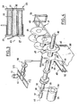
- the machine according to the invention comprises a frame 1 (FIG. 1) formed by a horizontal base part 2 and a vertical plate 3. Through this plate 3, is pivotally mounted a horizontal shaft 4 controlled by a motor 5, and carrying at its end 6 a circular plate 7 parallel to the plate 3.
- the axis 8 of the shaft 4 is the axis of symmetry of the plate 7 which can be rotated by the shaft 4.
- the plate 7 carries in its peripheral zone four shafts 9 reel holders mounted for rotation parallel to the axis 8 of the plate, these shafts 9 being equidistant from the center of the plate and being angularly offset by 90 ° relative to the other.
- a shaft 10 is rotatably mounted in the tray and protruding on either side of it, these shafts 10 being equidistant from the center of the tray and being angularly offset by 90 ° relative to each other.
- the shafts 10 are parallel to the axis 8.
- each shaft 10 is fixedly mounted an arm 12, perpendicular to the shaft 10, bearing at its distal end 13 of a block 14 perpendicular to the arm 12 and thus parallel to the axis of rotation 8 of the turntable 7.
- the shaft 10 carries a tongue 16, radial, substantially parallel to arm 12. Between this tongue 16 and the turntable 7, the shaft 10 comprises a cam disc 17.
- Each reel holder shaft 9 protrudes on either side of the plate 7.
- the end of the shaft part 9, located between the turntable 7 and the frame plate 3, carries a half-clutch 18.
- the another part 19, located on the other side of the turntable 7, forms a point or sleeve 20 suitable for being introduced into the bore 21 of the barrel 22 of a coil 23 (FIG. 3) with flanges 24 and 25 , said barrel 22 having radial holes 26, 27 formed near the internal face of the cheeks 24, 25, respectively, and opening into the bore 21 of the barrel.
- the spool pin 20 has a free end 28 of hemispherical shape and it carries, in its central region; radial and eclipsable lugs 29 which protrude relative to the diameter of the tip 20, being urged by springs, not shown, arranged inside the tip 20. These lugs 29 can be retracted by means of a linkage, not shown, arranged longitudinally in a bore of the shaft 9 and capable of being controlled from the end of this shaft 9, in the region of the half-clutch 18.
- the turntable 7 and the means which it carries can be pivoted step by step by 90 °, thus successively moving each spool 9 of the spool from a first position I called “loading” to a second position II called “winding” then at a third position III called “drying” and finally at a fourth position IV called "unloading".
- the half-clutch 18 carried by the shaft 9 is located opposite a half-clutch 30 carried by the end of a shaft 31 rotatably mounted in the plate 3 of the frame, parallel to the axis 8.
- this shaft 31 carries a pulley or gear 3 2 driven by means of a belt or chain 33 controlled by the pinion 34 of a motor 35.
- a rod 36 is mounted sliding in a longitudinal bore of the shaft 31, the projection relative to the half-clutch 30 of this rod 36 being suitable for controlling the retraction linkage of the pins 29 carried by the tip 20, the end of this linkage being located look, when the shaft 9 is at the loading station, of the end of the rod 36.
- the rod 36 can perform a back-and-forth movement relative to the shaft 31 by virtue of a control cylinder 37 placed in the extension of the rod 36, beyond the pulley or gear 32.
- the base 2 of the frame 1- carries a chair 38 ( Figure .4) comprising angles 39, 40 forming a raceway on which are arranged, one behind the other, empty coils 23 intended to be loaded.
- the raceway 41 formed by the angles is inclined, so that the coils, by gravity, are in abutment against each other, the first of these being stopped by a part of the chair 38 forming a stop 42 in a position where its axis 42 is the extension of the axis 44 of the spool pin 20 in the loading position I.
- the chair 38 and the raceway 41 are parallel to the plate 3 of the frame and are placed at such a distance from this plate that the first coil 45 carried by the chair is in the loading position in the immediate vicinity of the end. 28 of the tip 20.
- a jack 46 provided with a disc 47 at its active end close to the coil in position suitable for loading on the chair 38.
- the angle 40 of the chair 38 is interrupted near the stop 42, so as to allow longitudinal movement of the coil 45 along the axis 44.
- the vertical face 48 of the chair 38 located on the side of the turntable 7 carries a bracket 49 ( Figures 4 and 7) rotatably mounted on an axis 50 parallel to the axis 8 of the turntable.
- the oscillation of this bracket 49 is controlled by a jack 51 mounted oscillating around a fixed axis 52 secured to the chair 38 and parallel to the axis 8.
- the free end 53 of the bracket 49 carries a needle 54 arranged in the plane of the bracket 49 and on the side thereof which is opposite to the jack 5 1 .
- the needle 54 performs an oscillating movement in a plane perpendicular to the axis 44 of the spool holder shaft 9.
- the needle 54 comes into contact with a point 55 from the periphery of the tip 20, in the end zone of the latter.
- Each reel holder shaft 9 corresponds to an assembly 56 constituted, as described above, by a shaft 10, an arm 12, a shoe 14, a disc-carne 17 and a tongue 16.
- This assembly 56 can pivot from a position 57 ( Figure 1), where the arm 12 is substantially radial relative to the turntable 7 so as to be disengaged from the cheeks of the coil, at a position 58 in which the shoe 14 is applied against a generator 59 of the yarn of a coil 23 fitted on the tip 20.
- a spring not shown urges the seems 56 towards this last position, where the shoe 14 is in contact with the drum of the coil.
- the cam 17 of the shaft 10 is in contact with a plate 372 disposed in the extension of a ramp 172 secured to the frame of the machine and the junction of which will be explained below.
- the plate 372 is movable relative to the frame by means of an actuator 61 with rod 60. Under the action of the actuator 61, the plate 372 is applied by force against the cam 17 which is designed so as to then cause the rotation of the shaft 10 and the eclipse of the skate. brake 14 with respect to the coil.
- the jack 61 therefore makes it possible, thanks to the cam 17 and to the plate 372, to move the brake shoe 14 from an eclipsed position to a position applied against the drum of the coil.
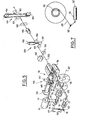
- a reel carried by a shaft 9 is near a cutting device 70.
- the axis 44 of the shaft 9 is in the extension the axis 7 1 of a shaft 72 rotatably mounted in the plate 3 of the machine frame, the half-clutch 18 of the shaft 9 being located opposite a half-clutch 73 carried by the end of the shaft 7 2 , the latter carrying at its other end a pulley or gear 74 controlled by a belt or chain 75 driven by the pinion 77 of a motor 76.
- the shaft reel holder 9 (FIG. 5) can be rotated by the motor 76.
- the cutting device 70 comprises a rigid frame 79, equipped with articulated feet 80 and 81 (FIG. 1) by which it is connected to a support plate 8 2 fixed to the plate 3 of the frame of the machine, the plate 82 being parallel at base 2 of the machine. Thanks to the articulations of the feet 80, 81, the frame 79, the feet 80 and 81, and the support plate 8 2 form a deformable parallelogram which allows the frame to cutting 79 to be moved parallel to the turntable 7, to the approximation and distance of a shaft 9. This movement is controlled by a jack 83 fixed to the frame 1 at a point 84. In Figure 1, the device cutting 70 carried by its frame 79 is shown in the position remote from the shaft 9.
- the cutting frame 79 is equipped with two smooth guide rods 85 and 86, on which slides a cutting plate 87, thanks to holes 88 and 89 made in the plate.
- Parallel to the guide rods is arranged a threaded rod 90 cooperating with a nut 91 integral with the plate 87, the rotation of the threaded rod 90 driven by means of a belt 9 2 by a motor 93 causing in known manner the displacement of the cutting plate 87 parallel to itself along the slides 86 and 85.
- the inversion of the direction of rotation of the motor 93 controls the reversal of the direction of movement of the cutting plate 87.
- a counter plate 94 of cutting is fixed to the plate 87 by screws 95.
- This counter-plate 94 carries an axis 96 parallel to the rods 85, 86 and having at its end a pulley 97 rotary, grooved 98, and a tubular wire guide 99 rotatably mounted on the axis 96 in the plane of the pulley 97, by means of two ears 100, 101, arranged on either side of the pulley 97.
- the shape of the ears 100 and 101 is such that the axis of the thread guide 99 is substantially tangent to the groove 98.
- the wire guide 99 stressed if necessary is by a spring, not shown, towards its horizontal position, can pivot around the axis 96 and thus take various angular positions.
- the end 102 of the wire guide 99 is bevelled, so as to be close to the portion of the periphery of the pulley 97 which faces it.
- a wire guide tube 104 fixed to post to the plate 94.
- a second wire guide tube 105 At a certain distance behind the tube 104 and on the same axis 103 is fixed to the plate 94 a second wire guide tube 105 itself followed, on the same axis device 106 with parallel vertical rotary fingers 107 and 108, and horizontal 108 ', the device 106 being fixed to the plate 87.
- An assembly or capstan 109 is fixed to the cutting frame 79, in the end zone of the bars 85, 86 of guide; dage of the cutting plate 87.
- This assembly 109 comprises a smooth rod 110, mounted in bearings 111 and 112 integral with the frame 79, the rotation of the rod 110 being able to be controlled by a motor 113 by means of a belt 114 and a pulley 115.
- On the smooth rod 110 is rotatably mounted a semi-circular plate 116 and carrying on its periphery teeth 117.
- To the plate 116 is fixed an arm 118 radial carrying at its end a pulley 119 free in rotation and controlled by a small pulley 120 of which it is integral.
- the pulley 120 is driven by a belt 121 which cooperates on the other hand with a pulley 122 fixed to the rod 110.
- a tongue 123 pivotally connected to the end of the rod 124 of a jack 125.
- the jack 125 is pivotally mounted to the frame 79.
- the teeth 117 of the plate 116 cooperate with the teeth 126 of a semi-circular plate 127 arranged in the same plane as the plate 116.
- the plate 127 is integral with an axis 128 movable in rotation in a bearing 129 integral with the frame 79.
- From the plate 127 also depends an arm 130 of length equal to that of the arm 118, and at the end of which is placed a pulley 131 free in rotation and parallel to the pulley 119.
- the arms 118 and 130 can be brought together or distant in their common plane symmetrically in the manner of scissors, the pulleys 119 and 131 being able to come into contact with each other through a point on their periphery 132, 1 33, respectively.
- the pulleys 119 and 131 are held apart by the play of a spring 134 acting on the plate 127.
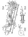
- a slide 135 ( Figures 2 and 5) fixed in overhang to the plate 3 of the chassis in parallel to rods 85 and 86 for guiding the cutting.
- On this slide is slidably mounted an assembly 136 biased towards the free end of the slide 135 by a spring 137.
- a return cylinder 138 with an axis parallel to the slide 135, is arranged below the slide, its rod , carrying an end stop 139, sliding in an eyelet integral with the crew 136.
- the jack 138 is fixed in position relative to the slide 135.
- a shearing device 141 On the crew 136 is mounted a shearing device 141, the blades of which are directed downwards and positioned so as to exactly overhang the axis 103 of the wire guide 99, beyond its free end 142, the diameter of the guide -wire corresponding to that of the treated wire. Thanks to a jack 143, the shears 141 can be raised or lowered. The cutting movement of the shears 141 is controlled by an electromechanical device 144.
- the crew 136 carries an adhesive deposition tube 145 connected to a reservoir of adhesive not shown. The tubing 145 being fixed to the body of the shears, it is lowered or lifted by the jack 143.
- the cutting axis of the shears 141 and the end of the tubing 145 are located in the plane of the wire guide 99 and the pulley 97.
- the tongue 16 carried by the shaft 10 controlling the shoe 14 associated with said shaft 9 is opposite of the rod 150 of a jack 151 fixed to the frame of the machine.
- the rod 150 is put protruding from the jack 151, its end 152 comes into contact with the tongue and causes, by leverage, the rotation of the shaft 10, against the force of the return spring which equips it, and this results in the distance of the shoe 14 relative to the shaft 9.
- a wire winding station 2 is additionally associated with a device (FIG. 9) constituted by a jack 166 fixed relative to the frame of the machine, the l axis 167 is placed in the extension of the axis of the spool 9 and whose end of the rod 168 carries a part 169 sliding under the action of the jack in the extension of the spool 20 and mobile in rotation.
- This piece 169 can be applied by the jack 166 against the hemispherical end 28 of the tip and thus wedge a wire 170 disposed between this piece and the tip.
- the speed of the reciprocating movement of the cutting device is adjusted as a function of the speed of rotation of the spool-holder shaft 9, and this by means of a counter Towers 171 fixed at the end of the shaft 72, this tachometer advantageously being an electro-optical oven counter comprising a perforated circular disc secured to the shaft 72 and an electro-optical pulse counter.
- the cutting speed being linked to the number of pulses produced by the tachometer, this speed can easily be adjusted according to the desired pitch for the winding of the wire, by simply changing the perforated disc, each perforated disc having a number of different perforations. For a winding with contiguous turns, the cutting pitch is equal to the diameter of the treated wire.
- a ramp 172 is fixed to the frame 1 so as to cooperate with the cam disc 17 carried by the shaft 10, to cause the rotation of the shaft 10 and the distance of the shoe 14 relative to the shaft 9, from that begins the movement of the reel holder 9 from position III to position IV.
- the shoe holder arm 12 is thus kept overshadowed by the ramp 172 until the shaft 9 with which it is associated has returned to the position I for loading a new empty reel.
- the end 372 of the ramp 172 is itself eclipsable by the jack 61 to allow the shoe 14 to come into bearing position against the spool holder shaft 9 when the latter has been again filled with an empty reel.
- the wire 200 (FIG. 5), coming from a debit station not shown, is successively disposed in the wire accumulator 161, the non-return 160, the controllable brake 159, the loop forming device 201, the length counter 153, then is introduced into the wire guide device 106, the wire guide tube 105, the wire guide tube 104 and finally the wire guide tube 99.
- the end of the wire is flush with the end 142 of the thread guide 99.
- a reel 45 is located in the extension of the reel-holder shaft 9, in the loading position I. Thanks to the jack 36, the pins 29 are retracted into the sleeve reel holder 19. By the jack 46 and its plate 47, the reel 45 is pushed towards the tip 20 which is housed in the bore 21 of the reel. The reel 45 having been moved away from the chair 38, a next reel comes into the loading position.
- the pins 29 are released and come to force force, thanks to the springs of the linkage, against the bore 21 of the coil, blocking the latter in position on the tip 20.
- the motor 35 is then excited and it controls, via the two half-clutches 18 and 30, the slow rotation of the spool pin shaft as the needle 54 of the bracket 49 is pressed against the external face of the barrel 22 of the coil, by retraction of the jack 51.
- the position of the bracket 49 is such that the needle 54 is in the same plane as the holes 26 presented by the barrel of the coil, that is to say a plane substantially tangent to the internal face of the cheek 24 of the coil.
- the clutch 18, 30 is of the sliding type, that is to say that the rotation of the shaft 9 stops when the needle is introduced into the hole 26, even if the shaft 31 continues to be driven. by the motor 35. After a predetermined time, the motor 35 is stopped.
- the motor 5 is excited and controls the rotation of the turntable 7 by 90 ° in the counterclockwise direction in the figure to bring the shaft 9 and the coil which it carries to the position II called "winding".
- the angular position 210 of the hole 26 is known, the coil having been maintained relative to the turntable by the shoe 14 o
- the cutting plate 87 and the elements which it carries are moved by rotation of the motor 93 driving the drive screw 90, until the extreme position where the yarn guide 99 is substantially in the plane tangent to the inner face of the flange 24 of the coil, and thus in the plane of the hole 2 6 of the barrel.
- the pulleys 119 and 131 of the capstan 109 are located on either side of the part of wire left free between the wire guides 104 and 105.
- the wire brake 159 is applied.
- the cylinder 83 is protruding, which brings the cutting assembly 70 closer to the axis of the coil, by the play of the joints legs 80 and 81.
- Advance on the rods 80 and 81 of the cutting table causes the end of the wire to enter into the wire guide 99, which has the effect of rounding the end and absorb the loop formed during the return to horizontal position of the thread guide 99.
- the thread guide 99 biased by spring, is in the axis of the thread guide 104, and the movement of the assembly cutting 70 controlled by the cylinder 83 is provided so that the end 142 of the wire guide 99 comes to be placed exactly opposite and near the hole 26 of the barrel of the coil.
- the jack 125 controls the approximation of the pulleys 119 and 131 of the capstan 109. Said pulleys press the wire in its portion between the wire guides 104 and 105.
- the jack 158 of the loop forming device 201 is retracted, which releases a handle formed beforehand, the length of said handle being equal to the length of the internal free loose end desired for the wire wound on the spool, increased by the length of wire absorbed when advancing the cutting table.
- the motor 113 is excited, which controls the rotation of the pulley 119 of the capstan 109. This rotation causes the advancement of the thread in the thread guide 99 until the slack formed by the handle released by the device 201 is exhausted.
- the desired length of wire is thus introduced through the wire guide 99 into the hole 26 of the spool of the spool, the free end thus formed penetrating into the bore 21 of the spool and being deflected towards the outside of the spool by the hemispherical end 28 of the tip 20 of the reel holder.
- the jack 166 is actuated and the part 169 jams the wire 170 against the tip 20. Thanks to this precaution, the wire is secured to the coil and its winding begins without sliding in the hole 26 when the coil is rotated. After the start of the winding, the jack 166 is retracted. If the wound wire is rigid enough, this precaution is not necessary because the wire gets stuck by itself enough in hole 26 to allow the start of winding.
- the jack 125 is retracted, which causes the pulleys 119 and 131 to move away.
- the rod 150 of the jack 151 is extended and moves the shoe 14 away. of the drum of the coil by acting on the tongue 16 of the shaft 10.
- the controllable brake 159 is released.
- the coil can then be rotated.
- the motor 76 is excited, controlling the rotation of the spool thanks to the cooperation of the half-clutches 18 and 73.
- the retraction of the rod of the jack 83 causes the recoil of the cutting table.
- the cutting is carried out in the usual way according to the speed of rotation of the coil detected by the device 171.
- the winding of the wire continues until the predetermined length to be wound is detected by the counter 153. During the winding of the wire, a new loop is formed by the device 201.
- the output of the actuator rod 138 is controlled, which frees the crew 136 which comes to position itself automatically by the play of the spring 137 and the stop of the part 140 of the crew against the cutting plate 87 , above the wire guide 99.
- the motor 76 After a deceleration phase, is stopped, which results in stopping the cutting.
- the mobile part of the crew 136 is lowered under the action of the jack 143, the shears 141 overlaps the wire between its exit from the wire guide 99 and its point of contact with the sheet of underlying turns, and the glue deposition tube 145 is placed above the wire between said contact point and the wire guide 99.
- a point of adhesive is deposited by the tubing 145 on the wire, then the motor 76 is excited to cause the low speed rotation of the spool on which this spool spools the wire until reaching the desired length of wire for the outer free end, this length being measured by a counter.
- the point of adhesive carried by the wire is thus applied against the adjacent turns, achieving the fixing of the external free end.
- the rod 150 of the jack 151 is retracted and the arm 12, under the action of its spring, comes to apply the shoe 14 against the upper sheet of wire wound on the spool.
- the pad firmly holds the last turns of wound wire, in particular the last carrying the glue, coming to apply beyond the point of glue.
- the shears 141 is actuated to cut the wire.
- the thread guide 99 which, during winding, is oriented, by virtue of its pivoting attachment to the axis 76, towards the instantaneous point of tangency of the thread on the preceding ply of thread, returns to its rest position where it is an extension of the wire guides 104 and 105. At this time, a loop is formed near the pulley 97: the advance of the cutting table during the subsequent operation makes it possible to eliminate it.
- the movable part of the crew 136 is brought up by the jack 143 and the crew 136 itself is brought back to its rest position by the retraction of the rod of the jack 138 whose end 139 abuts against the crew's eyelet 136.
- the cutting plate 87 is brought back by actuation of the motor 93 to its extreme initial position, near the capstan 109. Finally, the half-clutches 18 and 73 are freed from each other.
- the motor 5 controls the 90 ° rotation of the turntable, which brings the packed spool to the so-called drying position III, where the thread is held on the spool by the shoe 14.
- the operation of winding the thread on the reel being the longest of the four loading, winding, drying and unloading operations, it is the end of the winding operation at station II, described above, which controls the rotation of a quarter turn of the turntable.
- the turntable again rotates 90 ° under the action of the motor 5 to bring the full reel from the drying position III to the unloading position IV.
- the cam disc 17 of the shaft 10 comes into contact with the ramp 172, which causes the shoe 14 to be lifted and thus release the rotation of the coil.
- the washer 173 carried by the shaft 9 comes into contact with the belt 272, which causes the coil to rotate by rolling the washer 173 on the belt 272.
- the length of the belt 272 and the diameter of the washer 173 are provided so that, when the full reel reaches the unloading position IV, the external free end 190 of the reel is located in the upper part of said reel so as not to hinder the operations of unloading which will be described.
- the means with jacks provided in the extension of the shaft 9 are actuated to cause the retraction of the lugs 29 and, thus, the release of the coil.
- the coil is pulled longitudinally out of its engagement on the tip 20 and is deposited on the inclined ramp 180 on which it is evacuated by rolling.
- the arm 12 is provided a brake shoe 14 of length substantially equal to the width of the coils.
- the extreme position of the cutting device can also be adjusted so that the wire guide 99, in this extreme position, is in a plane substantially tangent to the outer cheek of the coil.
- the various motors fitted to the machine are of the variable speed type.
- the object pursued by the invention is achieved, that is to say the supply of coils furnished with wire arranged in contiguous turns and in successive layers, and having two free ends extended , one by a radial hole presented by the barrel of the coil, and the other in the extension of the last turn of the last layer, without requiring fixing of said wire; to one of the cheeks of the coil and without changing the pitch of the winding at its end. Thanks to the bonding of the wire at the end of the winding, the coil obtained is of a very clear appearance and the wire is not subjected to excessive stresses. The electrical tests of the wire are easily done by connecting the two free ends and the unwinding of the wire can be done after simple peeling by tearing off the point of glue.
Applications Claiming Priority (2)
| Application Number | Priority Date | Filing Date | Title |
|---|---|---|---|
| FR7932102 | 1979-12-31 | ||
| FR7932102A FR2472532A1 (fr) | 1979-12-31 | 1979-12-31 | Machine pour enrouler du fil sur des bobines |
Publications (1)
| Publication Number | Publication Date |
|---|---|
| EP0031783A1 true EP0031783A1 (de) | 1981-07-08 |
Family
ID=9233331
Family Applications (1)
| Application Number | Title | Priority Date | Filing Date |
|---|---|---|---|
| EP80401891A Ceased EP0031783A1 (de) | 1979-12-31 | 1980-12-30 | Maschine zum Aufwickeln von Draht auf Spulen |
Country Status (2)
| Country | Link |
|---|---|
| EP (1) | EP0031783A1 (de) |
| FR (1) | FR2472532A1 (de) |
Cited By (4)
| Publication number | Priority date | Publication date | Assignee | Title |
|---|---|---|---|---|
| EP0134665A1 (de) * | 1983-07-12 | 1985-03-20 | Cortinovis S.P.A. | Spulmaschine |
| EP0150783A2 (de) * | 1984-01-21 | 1985-08-07 | Heinz Bauer | Verfahren, Vorrichtung und Spulenkörpern zum Aufwickeln von Formbändern |
| US4708298A (en) * | 1984-06-20 | 1987-11-24 | Bicc Public Limited Company | Winding apparatus |
| EP0267157A2 (de) * | 1986-11-03 | 1988-05-11 | Maillefer S.A. | Doppeldrahtaufspulmaschine mit drehbarem Spulenhalter |
Families Citing this family (2)
| Publication number | Priority date | Publication date | Assignee | Title |
|---|---|---|---|---|
| SE504021C2 (sv) * | 1995-01-26 | 1996-10-21 | Windak Ab | Anordning för automatisk upptagning av kabel, vajer lina eller dylikt |
| CN112607510B (zh) * | 2020-12-17 | 2023-10-31 | 岳西县和祥电子科技有限公司 | 一种电线用防缠绕卷收胚 |
Citations (8)
| Publication number | Priority date | Publication date | Assignee | Title |
|---|---|---|---|---|
| FR1117576A (fr) * | 1954-12-27 | 1956-05-24 | Telecommunications Sa | Enrouloir continu automatique |
| FR1311606A (fr) * | 1961-01-19 | 1962-12-07 | Appareil pour l'enroulement ou le bobinage de fils métalliques ou de câbles arrivant d'une machine à gainer ou similaire | |
| US3259336A (en) * | 1964-04-08 | 1966-07-05 | Automation Machines & Equipmen | Coil winding machine |
| LU67348A1 (de) * | 1972-04-05 | 1973-06-18 | ||
| CH582106A5 (en) * | 1974-07-23 | 1976-11-30 | Maillefer Sa | Twisting device for large dia. cables - having drawing and feed devices mounted on support moveable between winding up positions |
| DE2603861A1 (de) * | 1974-01-25 | 1977-08-11 | Skaltek Ab | Wickelvorrichtung fuer fadenfoermiges gut |
| FR2375129A1 (fr) * | 1976-12-21 | 1978-07-21 | Somifra | Dispositif d'accrochage automatique d'un tube souple a enrouler en couronne |
| US4147310A (en) * | 1978-05-17 | 1979-04-03 | Piedmont Wire Corporation | Apparatus for coiling wire |
-
1979
- 1979-12-31 FR FR7932102A patent/FR2472532A1/fr active Granted
-
1980
- 1980-12-30 EP EP80401891A patent/EP0031783A1/de not_active Ceased
Patent Citations (8)
| Publication number | Priority date | Publication date | Assignee | Title |
|---|---|---|---|---|
| FR1117576A (fr) * | 1954-12-27 | 1956-05-24 | Telecommunications Sa | Enrouloir continu automatique |
| FR1311606A (fr) * | 1961-01-19 | 1962-12-07 | Appareil pour l'enroulement ou le bobinage de fils métalliques ou de câbles arrivant d'une machine à gainer ou similaire | |
| US3259336A (en) * | 1964-04-08 | 1966-07-05 | Automation Machines & Equipmen | Coil winding machine |
| LU67348A1 (de) * | 1972-04-05 | 1973-06-18 | ||
| DE2603861A1 (de) * | 1974-01-25 | 1977-08-11 | Skaltek Ab | Wickelvorrichtung fuer fadenfoermiges gut |
| CH582106A5 (en) * | 1974-07-23 | 1976-11-30 | Maillefer Sa | Twisting device for large dia. cables - having drawing and feed devices mounted on support moveable between winding up positions |
| FR2375129A1 (fr) * | 1976-12-21 | 1978-07-21 | Somifra | Dispositif d'accrochage automatique d'un tube souple a enrouler en couronne |
| US4147310A (en) * | 1978-05-17 | 1979-04-03 | Piedmont Wire Corporation | Apparatus for coiling wire |
Cited By (7)
| Publication number | Priority date | Publication date | Assignee | Title |
|---|---|---|---|---|
| EP0134665A1 (de) * | 1983-07-12 | 1985-03-20 | Cortinovis S.P.A. | Spulmaschine |
| EP0150783A2 (de) * | 1984-01-21 | 1985-08-07 | Heinz Bauer | Verfahren, Vorrichtung und Spulenkörpern zum Aufwickeln von Formbändern |
| EP0150783A3 (de) * | 1984-01-21 | 1987-04-15 | Heinz Bauer | Verfahren, Vorrichtung und Spulenkörpern zum Aufwickeln von Formbändern |
| US4708298A (en) * | 1984-06-20 | 1987-11-24 | Bicc Public Limited Company | Winding apparatus |
| US4765553A (en) * | 1984-06-20 | 1988-08-23 | Bicc Public Limited Company | Winding apparatus |
| EP0267157A2 (de) * | 1986-11-03 | 1988-05-11 | Maillefer S.A. | Doppeldrahtaufspulmaschine mit drehbarem Spulenhalter |
| EP0267157A3 (de) * | 1986-11-03 | 1988-08-10 | Maillefer S.A. | Doppeldrahtaufspulmaschine mit drehbarem Spulenhalter |
Also Published As
| Publication number | Publication date |
|---|---|
| FR2472532B1 (de) | 1985-05-10 |
| FR2472532A1 (fr) | 1981-07-03 |
Similar Documents
| Publication | Publication Date | Title |
|---|---|---|
| FR2500274A1 (fr) | Dispositif de fourniture automatique de bobines | |
| CH618141A5 (en) | Method and automatic device for coiling a hose | |
| BE1004174A7 (fr) | Bobineuse de cable. | |
| EP0331634B1 (de) | Verfahren und Apparat für das Öffnen einer Papierbandspule | |
| FR2879580A1 (fr) | Appareil dans une machine de preparation de filature,par exemple une carde, un mecanisme d'etirage de carde,un cadre d'etirage, une peigneuse ou equivalent, destine a changer des pots a ruban | |
| CH381578A (fr) | Dispositif pour recevoir automatiquement et de façon continue un ruban de fibre textile distribué par un premier métier d'étirage et fournir le ruban ainsi reçu sous forme de plusieurs rubans à un second métier d'étirage | |
| EP0031783A1 (de) | Maschine zum Aufwickeln von Draht auf Spulen | |
| CH633835A5 (fr) | Dispositif automatique de levee de bobines sur une machine de formation de bobinages. | |
| CH616829A5 (en) | automatic machine for making a clove hitch with a cord around an object and use of the machine | |
| EP0921074B1 (de) | Verfahren und Vorrichtung zum Zusammenfügen von ausgerichteten Gegenständen mittels Klebebändern | |
| CH453027A (fr) | Dispositif d'enroulement continu de fil sur des bobines réceptrices | |
| EP1611043B1 (de) | Vorrichtung zum anbringen und abnehmen von hülsen für fäden in einer textilmaschine | |
| FR2770503A1 (fr) | Machine d'enroulement de produit continu sous forme de feuille, pour former des bobines | |
| FR2482570A1 (fr) | Dispositif pour l'enroulement automatique de produits filiformes, notamment de fil metallique | |
| FR2552745A1 (fr) | Procede et appareil pour fixer un fil a un bobinoir | |
| FR2663916A1 (fr) | Dispositif de dechargement automatique de bobines textiles. | |
| EP0011006A1 (de) | Verfahren und Vorrichtung zum Aufwickeln von Schrottband | |
| BE896028A (fr) | Procede et appareil pour envider des fibres de verre | |
| EP0358890B1 (de) | Vorrichtung zum Wiederaufwickeln einer dünnen Bahn | |
| EP0267157A2 (de) | Doppeldrahtaufspulmaschine mit drehbarem Spulenhalter | |
| EP0526358A1 (de) | Vorrichtung zum Abgeben und gleichzeitigem Schneiden von aufgerolltem Bahnmaterial | |
| EP1112954B1 (de) | Vorrichtung und Verfahren zum Knoten, Etikettieren und Palettieren von Spulen am Ende einer Maschine zur Spulenherstellung | |
| CH644329A5 (fr) | Dispositif pour effectuer la separation des parties terminales des fils conducteurs dans une machine a enrouler automatique. | |
| CH343350A (fr) | Dispositif d'accumulation et de transport d'un élément filiforme | |
| CH673998A5 (de) |
Legal Events
| Date | Code | Title | Description |
|---|---|---|---|
| PUAI | Public reference made under article 153(3) epc to a published international application that has entered the european phase |
Free format text: ORIGINAL CODE: 0009012 |
|
| AK | Designated contracting states |
Designated state(s): AT BE CH DE GB IT LU NL SE |
|
| 17P | Request for examination filed |
Effective date: 19811218 |
|
| STAA | Information on the status of an ep patent application or granted ep patent |
Free format text: STATUS: THE APPLICATION HAS BEEN REFUSED |
|
| 18R | Application refused |
Effective date: 19840604 |
|
| RIN1 | Information on inventor provided before grant (corrected) |
Inventor name: LEMAIRE, ROLAND |