EP0020966B1 - Vorrichtung zum Ausscheiden von Probe- und Makulaturexemplaren in einer Druckmaschine - Google Patents
Vorrichtung zum Ausscheiden von Probe- und Makulaturexemplaren in einer Druckmaschine Download PDFInfo
- Publication number
- EP0020966B1 EP0020966B1 EP19800102550 EP80102550A EP0020966B1 EP 0020966 B1 EP0020966 B1 EP 0020966B1 EP 19800102550 EP19800102550 EP 19800102550 EP 80102550 A EP80102550 A EP 80102550A EP 0020966 B1 EP0020966 B1 EP 0020966B1
- Authority
- EP
- European Patent Office
- Prior art keywords
- coupling
- cylinder
- coupling half
- spindle
- disengagement
- Prior art date
- Legal status (The legal status is an assumption and is not a legal conclusion. Google has not performed a legal analysis and makes no representation as to the accuracy of the status listed.)
- Expired
Links
- 238000010168 coupling process Methods 0.000 claims description 40
- 230000008878 coupling Effects 0.000 claims description 38
- 238000005859 coupling reaction Methods 0.000 claims description 38
- 230000033764 rhythmic process Effects 0.000 claims description 4
- 230000001419 dependent effect Effects 0.000 claims 1
- 238000009795 derivation Methods 0.000 description 15
- 239000002699 waste material Substances 0.000 description 8
- 238000006073 displacement reaction Methods 0.000 description 3
- 238000000034 method Methods 0.000 description 2
- 230000005540 biological transmission Effects 0.000 description 1
- 210000000078 claw Anatomy 0.000 description 1
- 238000011161 development Methods 0.000 description 1
- 230000018109 developmental process Effects 0.000 description 1
- 230000008030 elimination Effects 0.000 description 1
- 238000003379 elimination reaction Methods 0.000 description 1
- 230000002028 premature Effects 0.000 description 1
- 230000001020 rhythmical effect Effects 0.000 description 1
- 238000010079 rubber tapping Methods 0.000 description 1
- 230000001360 synchronised effect Effects 0.000 description 1
Images


Classifications
-
- B—PERFORMING OPERATIONS; TRANSPORTING
- B65—CONVEYING; PACKING; STORING; HANDLING THIN OR FILAMENTARY MATERIAL
- B65H—HANDLING THIN OR FILAMENTARY MATERIAL, e.g. SHEETS, WEBS, CABLES
- B65H29/00—Delivering or advancing articles from machines; Advancing articles to or into piles
- B65H29/58—Article switches or diverters
- B65H29/585—Article switches or diverters taking samples from the main stream
-
- B—PERFORMING OPERATIONS; TRANSPORTING
- B65—CONVEYING; PACKING; STORING; HANDLING THIN OR FILAMENTARY MATERIAL
- B65H—HANDLING THIN OR FILAMENTARY MATERIAL, e.g. SHEETS, WEBS, CABLES
- B65H29/00—Delivering or advancing articles from machines; Advancing articles to or into piles
- B65H29/58—Article switches or diverters
- B65H29/62—Article switches or diverters diverting faulty articles from the main streams
-
- B—PERFORMING OPERATIONS; TRANSPORTING
- B65—CONVEYING; PACKING; STORING; HANDLING THIN OR FILAMENTARY MATERIAL
- B65H—HANDLING THIN OR FILAMENTARY MATERIAL, e.g. SHEETS, WEBS, CABLES
- B65H45/00—Folding thin material
- B65H45/12—Folding articles or webs with application of pressure to define or form crease lines
- B65H45/16—Rotary folders
- B65H45/162—Rotary folders with folding jaw cylinders
- B65H45/167—Rotary folders with folding jaw cylinders having associated sheet guide means
Definitions
- the invention relates to a device for separating specimen and waste copies from a cylinder by means of switches arranged on a pivotable spindle, which strip the printed copies from the cylinder in the engaged state, coupling means being provided through which the spindle can be pivoted and further means are provided which only permit engagement and disengagement if they cannot hit an arc guided by the cylinder.
- the object of the invention is to provide a device for the optional removal of specimen and waste copies during machine operation by means of switches which can be set on a folding jaw cylinder, with which an exactly controllable removal of sample and waste specimens is possible directly from the folding cylinder. This object is achieved by the application of the characterizing features of claim 1.
- a switch control device is already known from US-A-3 206 191, which comprises two coupling halves, one of which can be pivoted about a spindle in the rhythm of incoming printed copies and the other can be moved axially on this spindle, but with this known control device During the machine run, it is not possible to individually determine in which of two outgoing transport paths an incoming print copy should be inserted. The optional removal of copies from the incoming product stream is therefore not possible with this known device.
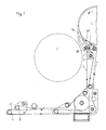
- a folding jaw cylinder 1 shows a folding jaw cylinder 1, from which folding products can either be transferred to a paddle wheel 2 for further processing, or can be fed to a removal point 10, for example, as specimen and waste copies.
- Derivatives 3a which are arranged on an axis running parallel to the axis of the jaw cylinder 1, can be adjusted on the jaw cylinder 1 in such a way that they come to lie below the outer surface of the jaw cylinder 1. In this position, the derivations 3a cause the folded products to be stripped from the folding jaw cylinder 1, so that they get into the paddle wheel 2.
- a folding copy arrives via a derivation 3b, which is always arranged below the surface of the folding jaw cylinder 1, on a conveyor belt consisting of two tracks 4 and 5.
- the webs 4 and 5 run together via deflection rollers 6 and 7 on a band merging roller 11, so that a folded copy stripped by the diversions 3b between the deflection rollers 6 and 7 is grasped and held by the two webs on the band merging roller 11, so that it becomes Tapping point 10 can be transported.
- the two webs 4 and 5 diverge again at the deflection rollers 8 and 9.
- a number of further tape guide or deflection rollers are shown, which are not specifically identified. These can be used to determine the routing of the individual tracks according to the respective circumstances.
- control device for timely, exact and fast control of the derivations 3a is shown in detail.
- the folding jaw cylinder 1 indicated in FIG. 2b has an axis 41 on which a cam disk 40 is arranged so that it rotates synchronously with the folding jaw cylinder 1.
- the cam disk 40 has a clutch section between switching points 12 and 13, by means of which, as will be described in detail below, the timing of the derivations 3a is determined.
- the cam disk 40 is sensed by a scanning roller 31.
- the scanning roller 31 is rotatably arranged on a bearing pin 16 which is fixed to the fork-shaped end of a bearing lever 15. With its other end is the bearing lever 15 rotatably arranged on a fixed bearing pin 14. Since the scanning roller 31 is pressed against the cam plate 40, the bearing lever 15 is pivoted rhythmically when the jaw cylinder 1 or the cam plate 40 rotates according to the curve shape of the cam plate 40 around the fixed bearing pin 14.
- a shift lever 17 is rotatably arranged on the bearing pin 16 with its upper fork-shaped end.
- the lower end of the shift lever 17 is also fork-shaped and comprises a connecting bolt 21. While the shift lever 17 is rotatably arranged with its upper fork-shaped end on the bearing pin 16 and with its lower fork-shaped end on the connecting bolt 21, the bearing lever 15 with its fixed lower fork-shaped end on the bearing pin 16 by a locking screw and by a press fit, so that it is only pivotable about the fixed bearing pin 14.
- Half of an end coupling preferably a claw coupling, is also connected to the connecting bolt 21.
- This first half 34 of the coupling is arranged on a bearing spindle 18 via a bearing 38.
- the support spindle 18 (only partially shown) runs parallel to the folding jaw cylinder 1.
- a number of derivations 3a (only one derivation tongue is shown in FIG. 2a) are fixedly arranged on the support spindle 18. With the right, d. H. The end, not shown in Fig. 2a, the support spindle 18 is arranged in a suitable bearing in the machine side wall.
- the support spindle 18 is biased at the right bearing point of the support spindle 18 using conventional means, for example a spring, in such a way that the derivations 3a engage in the jaw cylinder 1, i. H. come to rest under its surface.
- the folded copies are stripped from the jaw cylinder 1 through the diversions 3a and can be processed further by means of a paddle wheel 2 shown in FIG. 1.
- the scanning roller 31 is pressed against the surface of the cam plate 40 by a spring 20 arranged on a body 19 via a pin 30 and the bchaithebei 17. As a result, the movement of the scanning roller 31 is transmitted to the first half 34 of the clutch via the shift lever 17.
- the first half 34 of the coupling arranged on the supporting spindle 18 thus rotates according to the shape of the cam plate 40 by a small amount in the rhythm of the rotation of the jaw cylinder 1 and the cam plate 40 around the supporting spindle 18.
- the extent of the pivoting of the first half 34 of the coupling is relatively small and in any case smaller than the pitch of the clutch.
- the counterpart of the first half 34 is also arranged on the support spindle 18 and is referred to below as the second half 35.
- the second half 35 of the coupling is axially displaceable on the supporting spindle 18 via a longitudinal coupling bushing 44, but cannot be rotated about the supporting spindle 18.
- the first half 34 is pivoted around the supporting spindle 18 in the rhythm of the rotation of the jaw cylinder, while the second half 35 of the coupling on the supporting spindle 18, which is supported with its left end in a bearing 37 arranged in a side wall 39, is not influenced by this rhythmic pivoting movement.
- the coupling longitudinal guide bush 44 is fixed, i. H. neither axially displaceable nor rotatable, arranged on the support spindle 18, while the second half 35 of the coupling can carry out a movement in the axial direction on the coupling longitudinal guide bushing 44.
- FIG. 2a shows a pneumatic cylinder 28 which is fastened to the side wall 39 of the machine by means of screws 27.
- the pneumatic cylinder 28 is a double-acting cylinder, so that it can move in a known manner with the aid of an electromagnetic valve 42 and a compressed air system, not shown, to the left or right.
- This movement is used via a shift lever 23 for the axial displacement of the second half 35 of the clutch.
- the power transmission takes place with a bolt 29 via a sliding block, on which the lower end of the shift lever 23 pivotable about the bolt 22 is arranged, and the bolt 36 also via a sliding block, which also permits a rotary movement of the coupling part 35 when the lever 23 is stationary.
- a pivoting of the shift lever 23 about the pin 22 thus causes a displacement of the second half 35 of the first clutch on the support spindle 18 or on the clutch longitudinal guide bush 44.
- the pneumatic cylinder 28 is actuated with the help of the solenoid valve 42 in such a way that the shift lever 23 is pivoted about the pin 22 so that it is dashed in FIG. 2a shown position occupies.
- This pivoting movement about the bolt 22 counterclockwise causes a displacement of the second half 35 of the clutch so that it is pressed against the first half 34.
- An essential feature of the invention is that a timely clutch, d. H. a timely engagement of the two coupling parts is only possible if the scanning roller 31 runs over the coupling section between the switching points 12 and 13 on the cam plate 40, so that a synchronization of the coupling process is achieved based on the rotation of the jaw cylinder 1. If the scanning roller 31 is located above the coupling section of the cam plate 40, the first half 34 on the supporting spindle 18 assumes a position in which the two coupling parts can be engaged due to the pressure exerted by the pneumatic cylinder 28 on the second half 35 of the front coupling .
- a bevel is attached to the guide groove, through which it is achieved that the coupling process is completed mechanically accelerated in the event of a curve rise before complete disengagement.
- the pivoting movement of the first half 34 is transferred to the second half 35, so that the support spindle 18 is now pivoted so that the derivations 3a emerge from the jaw cylinder 1, i. that is, they are rotated counterclockwise in the illustration according to FIG. 2b.
- the movement of the pneumatic cylinder 28 is sensed by a roller 25 of a limit switch 24. As shown in FIG. 2a, the roller 25 of the limit switch 24 runs over a slope 26.
- the solenoid valve 42 can be actuated by a suitable control circuit (not shown) after a certain point in time reverse the pneumatic cylinder 28 so that the second half 35 of the clutch disengages. The time is measured so that each time after delivery of the second copy of the pneumatic cylinder, the coupling part 35 retracts in time so that the coupling can be disengaged when the coupling section of the cam is reached.
- the process described above can be repeated by means of the electrical control circuit, so that the derivatives 3a are cyclically lifted from the jaw cylinder 1. Such a repetition makes it possible for any number of specimens to be eliminated in succession.
- the pneumatic cylinder is only reversed at a correspondingly late point in time by the solenoid valve 42.
- the derivations 3a move back to the starting position after the elimination of two copies located on the jaw cylinder. but go back in the same gap, so that the fold copies can be eliminated continuously.
- the device according to the invention is provided with a catch 32 and 33.
- This fixed detent 32 and 33 enables decoupling, d. H. a disengagement of the second half 35 only at a certain position, so that the derivations 3a are avoided in a running sheet or a sample is avoided.
- the device according to the invention enables extremely fast and temporally and locally definable control of the derivations, since the engagement and disengagement processes are exactly synchronized with the rotation of the jaw cylinder and can be carried out very quickly.
Landscapes
- Engineering & Computer Science (AREA)
- Mechanical Engineering (AREA)
- Folding Of Thin Sheet-Like Materials, Special Discharging Devices, And Others (AREA)
Description
- Die Erfindung betrifft eine Vorrichtung zum Ausscheiden von Probe- und Makulaturexemplaren von einem Zylinder mittels auf einer schwenkbaren Spindel angeordneten Weichen, die die Druckexemplare von dem Zylinder im eingerückten Zustand abstreifen, wobei Kupplungsmittel vorgesehen sind, durch die die Spindel verschwenkbar ist und weitere Mittel vorgesehen sind, die ein Ein- und Ausrücken nur zulassen, wenn sie dabei nicht auf einen vom Zylinder geführten Bogen treffen können.
- Aus der DE-A-2 052 924 ist eine solche Einrichtung zum Ausscheiden von Kontroll- und Makulaturexemplaren in Falzapparaten bekannt. Bei dieser Einrichtung greift ein Anschlag in ein Schaufelrad ein und schiebt die ankommenden Druckexemplare aus dem Schaufelrad heraus. Dieser um einen Zapfen schwenkbare Anschlag kann durch einen Elektromagneten in eine unwirksame Stellung gebracht werden, so daß die Druckexemplare an ihm unbeeinflußt vorbeigeführt werden können. In einer nachgeordneten Entnahmestation erfolgt dann die Herausführung der Druckexemplare mit Hilfe eines Bandes und deren Weitertransport. Eine dieser Entnahmestationen dient zum Ausscheiden von Kontroll- und Makulaturexemplaren. Der den erwähnten Anschlag umfassende Steuermechanismus reagiert bei hohen Maschinengeschwindigkeiten träge, was u. U. zu einer nicht exakten Arbeitsweise führen kann.
- Die Aufgabe der Erfindung besteht darin, eine Vorrichtung zum wahlweisen Ausscheiden von Probe- und Makulaturexemplaren während des Maschinenlaufes mittels an einen Falzklappenzylinder anstellbaren Weichen aufzuzeigen, mit der eine exakt steuerbare Entnahme von Probe- und Makulaturexemplaren direkt aus dem Falzzylinder möglich ist. Diese Aufgabe wird durch die Anwendung der kennzeichnenden Merkmale des Anspruches 1 gelöst.
- Aus der US-A-3 206 191 ist zwar bereits eine Weichensteuervorrichtung bekannt, die zwei Kupplungshälften umfaßt, von denen die eine im Rhythmus von ankommenden Druckexemplaren um eine Spindel verschwenkbar und die andere axial auf dieser Spindel verschiebbar ist, jedoch kann mit dieser bekannten Steuervorrichtung während des Maschinenlaufes nicht individuell bestimmt werden, in welchen von zwei abgehenden Transportpfaden ein ankommendes Druckexemplar eingeschleust werden soll. Die wahlweise Entnahme von Exemplaren aus dem ankommenden Produktstrom ist somit mit dieser bekannten Vorrichtung nicht möglich.
- Weiterbildungen der Erfindung und deren Vorteile ergeben sich aus den Unteransprüchen in Verbindung mit der Beschreibung und den Zeichnungen. Im folgenden wird die Erfindung anhand eines Ausführungsbeispieles unter Bezugnahme auf die Zeichnungen beschrieben. In diesen zeigt
- Fig. 1 eine schematische Darstellung einer Vorrichtung zum Ausscheiden von Probe- und Makulaturexemplaren,
- Fig. 2a einen Längsschnitt der erfindungsgemäßen Vorrichtung und
- Fig. 2b einen Schnitt A-B der Darstellung gemäß Fig. 2a.
- In Fig. 1 ist ein Falzklappenzylinder 1 gezeigt, von dem Falzprodukte entweder zur weiteren Verarbeitung auf ein Schaufelrad 2 übertragen werden können oder beispielsweise als Probe-und Makulaturexemplare einer Entnahmestelle 10 zuführbar sind. An den Falzklappenzylinder 1 sind Ableitungen 3a, die auf einer parallel zu der Achse des Falzklappenzylinders 1 verlaufenden Achse angeordnet sind, so anstellbar, daß diese unterhalb der Manteloberfläche des Falzklappenzylinders 1 zu liegen kommen. In dieser Stellung bewirken die Ableitzungen 3a ein Abstreifen der Falzprodukte von dem Falzklappenzylinder 1, so daß diese in das Schaufelrad 2 gelangen.
- Durch Abstellen, d. h. Herausheben der Ableitzungen 3a aus dem Falzklappenzylinder 1, gelangt ein Falzexemplar über stets unterhalb der Manteloberfläche des Falzklappenzylinders 1 angeordneten Ableitzungen 3b auf ein Transportband, das aus zwei Bahnen 4 und 5 besteht. Die Bahnen 4 und 5 laufen über Umlenkrollen 6 und 7 an einer Bandzusammenführungsrolle 11 zusammen, so daß ein durch die Ableitzungen 3b abgestreiftes Falzexemplar zwischen den Umlenkrollen 6 und 7 von den beiden Bahnen an der Bandzusammenführungsrolle 11 erfaßt und festgehalten wird, so daß es zu der Entnahmestelle 10 transportiert werden kann. An der Entnahmestelle 10 laufen die beiden Bahnen 4 und 5 an den Umlenkrollen 8 und 9 wieder auseinander. Zwischen den Umlenkrollen 6, 7 und 8, 9 ist eine Anzahl weiterer Bandführungs- bzw. Umlenkrollen gezeigt, die nicht im einzelnen bezeichnet sind. Mit diesen kann die Führung der einzelnen Bahnen gemäß den jeweiligen Gegebenheiten festgelegt werden.
- In den Fig. 2a und 2b ist die erfindungsgemäße Steuervorrichtung zur zeitgerechten, exakten und schnellen Steuerung der Ableitzungen 3a im einzelnen dargestellt.
- Der in Fig. 2b angedeutete Falzklappenzylinder 1 weist eine Achse 41 auf, auf der eine Kurvenscheibe 40 angeordnet ist, so daß diese sich synchron mit dem Falzklappenzylinder 1 dreht. Die Kurvenscheibe 40 weist zwischen Schaltpunkten 12 und 13 eine Kupplungsstrecke auf, durch die, wie im nachfolgenden noch im einzelnen beschrieben wird, die zeitliche Steuerung der Ableitzungen 3a festgelegt wird.
- Die Kurvenscheibe 40 wird durch eine Abtastrolle 31 abgefühlt. Die Abtastrolle 31 ist drehbar auf einem Lagerbolzen 16 angeordnet, der an dem gabelförmigen Ende eines Lagerhebels 15 fixiert ist. Mit seinem anderen Ende ist der Lagerhebel 15 drehbar auf einem ortsfesten Lagerbolzen 14 angeordnet. Da die Abtastrolle 31 gegen die Kurvenscheibe 40 gedrückt wird, erfolgt ein rhythmisches Verschwenken des Lagerhebels 15 bei einer Rotation des Falzklappenzylinders 1 bzw. der Kurvenscheibe 40 entsprechend der Kurvenform der Kurvenscheibe 40 um den ortsfesten Lagerbolzen 14.
- Auf dem Lagerbolzen 16 ist, wie aus Fig. 2a am besten ersichtlich, drehbar ein Schalthebel 17 mit seinem oberen gabelförmigen Ende angeordnet. Das untere Ende des Schalthebels 17 ist ebenfalls gabelförmig ausgebildet und umfaßt einen Verbindungsbolzen 21. Während der Schalthebel 17 mit seinem oberen gabelförmigen Ende drehbar auf dem Lagerbolzen 16 und mit seinem unteren gabelförmigen Ende drehbar auf dem Verbindungsbolzen 21 angeordnet ist, wurde der Lagerhebel 15 mit seinem unteren gabelförmigen Ende auf dem Lagerbolzen 16 durch eine Feststellschraube und durch Preßsitz fixiert, so daß er lediglich um den ortsfesten Lagerbolzen 14 verschwenkbar ist.
- Mit dem Verbindungsbolzen 21 ist des weiteren eine Hälfte einer Stirnkupplung, vorzugsweise einer Klauenkupplung, verbunden. Diese erste Hälfte 34 der Kupplung ist über ein Lager 38 auf einer Tragspindel 18 angeordnet. Die Tragspindel 18 (nur teilweise dargestellt) verläuft parallel zu dem Falzklappenzylinder 1. Auf der Tragspindel 18 sind eine Anzahl Ableitzungen 3a (in Fig. 2a ist nur eine Ableitzunge gezeigt) fest angeordnet. Mit dem rechten, d. h. in Fig. 2a nicht gezeigten Ende ist die Tragspindel 18 in einem geeigneten Lager in der Maschinenseitenwand angeordnet. Des weiteren ist an der rechten Lagerstelle der Tragspindel 18 mit herkömmlichen Mitteln, beispielsweise einer Feder, die Tragspindel 18 so vorgespannt, daß die Ableitzungen 3a in den Falzklappenzylinder 1 eingreifen, d. h. unter dessen Oberfläche zu liegen kommen. Dadurch werden von dem Falzklappenzylinder 1 durch die Ableitzungen 3a die gefalzten Exemplare abgestreift und können über ein in Fig. 1 gezeigtes Schaufelrad 2 weiter verarbeitet werden.
- Die Abtastrolle 31 wird durch eine auf einem Körper 19 angeordnete Feder 20 über einen Stift 30 und den bchaithebei 17 gegen die Oberfläche der Kurvenscheibe 40 gedrückt. Dadurch wird die Bewegung der Abtastrolle 31 über den Schalthebel 17 auf die erste Hälfte 34 der Kupplung übertragen. Die erste Hälfte 34 der auf der Tragspindel 18 angeordneten Kupplung dreht sich somit entsprechend der Form der Kurvenscheibe 40 um ein geringes Ausmaß im Rhythmus der Rotation des Falzklappenzylinders 1 und der Kurvenscheibe 40 um die Tragspindel 18. Das Ausmaß der Verschwenkung der ersten Hälfte 34 der Kupplung ist relativ gering und in jedem Fall kleiner als die Teilung der Kupplung.
- Das Gegenstück der ersten Hälfte 34 ist ebenfalls auf der Tragspindel 18 angeordnet und wird im folgenden als zweite Hälfte 35 bezeichnet. Die zweite Hälfte 35 der Kupplung ist über eine Kupplungslängsführungsbuchse 44 auf der Tragspindel 18 axial verschiebbar, jedoch nicht um die Tragspindel 18 verdrehbar. Somit wird im entkuppelten Zustand die erste Hälfte 34 im Rhythmus der Rotation des Falzklappenzylinders um die Tragspindel 18 verschwenkt, während die zweite Hälfte 35 der Kupplung auf der Tragspindel 18, die mit ihrem linken Ende in einem in einer Seitenwand 39 angeordneten Lager 37 gelagert ist, von dieser rhythmischen Verschwenkbewegung nicht beeinflußt wird. Wie aus Fig. 2a hervorgeht, ist die Kupplungslängsführungsbuchse 44 fest, d. h. weder axial verschiebbar noch drehbar, auf der Tragspindel 18 angeordnet, während die zweite Hälfte 35 der Kupplung eine Bewegung in Axialrichtung auf der Kupplungslängsführungsbuchse 44 ausführen kann.
- In Fig. 2a ist ein Pneumatikzylinder 28 gezeigt, der mittels Schrauben 27 an der Seitenwand 39 der Maschine befestigt ist. Der Pneumatikzylinder 28 ist ein doppeltwirkender Zylinder, so daß er in bekannter Weise mit Hilfe eines Elektromagnetventils 42 und eines nicht gezeigten Druckluftsystems eine Bewegung nach links oder rechts ausführen kann. Diese Bewegung wird über einen Schalthebel 23 zur Axialverschiebung der zweiten Hälfte 35 der Kupplung verwendet. Die Kraftübertragung erfolgt mit einem Bolzen 29 über einen Gleitstein, an dem das untere Ende des um den Bolzen 22 schwenkbaren Schalthebels 23 angeordnet ist, und den Bolzen 36 ebenfalls über einen Gleitstein, der auch eine Drehbewegung des Kupplungsteils 35 bei stillstehendem Hebel 23 zuläßt. Eine Verschwenkung des Schalthebels 23 um den Bolzen 22 bewirkt somit eine Verschiebung der zweiten Hälfte 35 der ersten Kupplung auf der Tragspindel 18 bzw. auf der Kupplungslängsführungsbuchse 44.
- Im folgenden wird die Arbeitsweise der erfindungsgemäßen Vorrichtung beschrieben. Falls sich der Schalthebel 23 in seiner ausgezeichneten Stellung (Fig. 2a) befindet, steht die zweite Hälfte 35 der Kupplung nicht im Eingriff mit der ersten Hälfte 34. Somit werden die auf dem Falzklappenzylinder 1 befindlichen Falzprodukte 43 durch die Ableitzungen 3a abgestreift und gelangen in ein Schaufelrad (Schaufelrad 2 in Fig. 1), da durch die Vorspannung der Tragspindel 18 die auf dieser angeordneten Ableitzungen 3a in den Falzklappenzylinder eingedrückt werden. Bei dieser Arbeitsweise folgt, wie bereits dargelegt, die Abtastrolle 31 der Kurvenform der Kurvenscheibe 40 und führt jeweils zwischen den Schaltpunkten 12 und 13 eine Bewegung in Längsrichtung des Schalthebels 17 aus, wodurch eine Verschwenkung der ersten Hälfte 34 der Stirnkupplung um die Tragspindel 18 erfolgt.
- Wird nun die Aussondierung eines Falzexemplares gewünscht, so erfolgt mit Hilfe des Elektromagnetventils 42 eine Betätigung des Pneumatikzylinders 28 in der Weise, daß der Schalthebel 23 um den Bolzen 22 verschwenkt wird, so daß er die in Fig. 2a gestrichelt dargestellte Lage einnimmt. Diese Verschwenkbewegung um den Bolzen 22 entgegen der Uhrzeigerrichtung bewirkt eine Verschiebung der zweiten Hälfte 35 der Kupplung, so daß diese gegen die erste Hälfte 34 gedrückt wird.
- Ein wesentliches Merkmal der Erfindung liegt nun darin, daß eine zeitgerechte Kupplung, d. h. ein zeitgerechtes Einrücken der beiden Kupplungsteile nur dann möglich ist, wenn die Abtastrolle 31 über die Kupplungsstrecke zwischen den Schaltpunkten 12 und 13 auf der Kurvenscheibe 40 läuft, so daß eine Synchronisation des Einkuppelvorganges bezogen auf die Rotation des Falzklappenzylinders 1 erzeilt wird. Befindet sich die Abtastrolle 31 über der Kupplungsstrecke der Kurvenscheibe 40, so nimmt die erste Hälfte 34 auf der Tragspindel 18 eine Stellung ein, bei der infolge des durch den Pneumatikzylinder 28 auf die zweite Hälfte 35 der Stirnkupplung ausgeübten Andruckes ein Einrücken der beiden Kupplungsteile möglich ist. Bei der Rastung 32 und 33 ist an der Führungsnut eine Schräge angebracht, durch die erreicht wird, daß bei einem Kurvenanstieg vor vollständigem Ausrasten der Kupplungsvorgang mechanisch beschleunigt abgeschlossen wird. Nach dieser Einkupplung wird die Verschwenkbewegung der ersten Hälfte 34 auf die zweite Hälfte 35 übertragen, so daß nun auch die Tragspindel 18 so verschwenkt wird, daß die Ableitzungen 3a aus dem Falzklappenzylinder 1 heraustreten, d. h., sie werden in der Darstellung gemäß Fig. 2b entgegen der Uhrzeigerrichtung gedreht.
- Nun werden die ankommenden Falzprodukte 43 nicht mehr durch die Ableitzungen 3a abgestreift, sondern erst durch die Ableitzungen 3b (Fig.1), so daß eine Aussondierung der Probeexemplare erfolgt.
- Die Bewegung des Pneumatikzylinders 28 wird durch eine Rolle 25 eines Endschalters 24 abgetastet. Wie in Fig. 2a gezeigt, läuft die Rolle 25 des Endschalters 24 über eine Schräge 26. Sobald nun der Pneumatikzylinder 28 die vorangehend beschriebene Verschwenkung des Schalthebels 23 ausgeführt hat, kann durch eine geeignete Steuerschaltung (nicht gezeigt) nach einem bestimmten Zeitpunkt das Elektromagnetventil 42 eine Umsteuerung des Pneumatikzylinders 28 vornehmen, so daß ein Ausrücken der zweiten Hälfte 35 der Kupplung erfolgt. Die Zeit wird so bemessen, daß jeweils nach Abgabe des zweiten Exemplares der Pneumatikzylinder das Kupplungsteil 35 so rechtzeitig zurückzieht, daß beim Erreichen der Kupplungsstrecke der Kurvenscheibe das Auskuppeln erfolgen kann. Wahlweise kann sich der vorangehend beschriebene Vorgang mittels der elektrischen Steuerschaltung wiederholen, so daß zyklisch jeweils die Ableitzungen 3a von dem Falzklappenzylinder 1 abgehoben werden. Durch eine solche Wiederholung ist es möglich, daß nacheinander eine beliebige Anzahl von Probeexemplaren ausgeschieden werden.
- Falls eine große Anzahl von Makulaturexemplaren ausgesondert werden soll, erfolgt die Umsteuerung des Pneumatikzylinders erst zu einem entsprechend späten Zeitpunkt durch das Elektromagnetventil 42. In diesem Fall bewegen sich die Ableitzungen 3a jeweils nach dem Ausscheiden von zwei auf dem Falzklappenzylinder befindlichen Exemplaren in die Ausgangsstellung zurück, gehen aber noch in der gleichen Lücke zurück, so daß fortlaufend die Falzexemplare ausgeschieden werden können.
- Zur Vermeidung eines vorzeitigen Ausrückens der zweiten Hälfte 35 ist die erfindungsgemäße Vorrichtung mit einer Rastung 32 und 33 versehen. Diese ortsfeste Rastung 32 und 33 ermöglicht ein Entkuppeln, d. h. ein Ausrücken der zweiten Hälfte 35, erst bei einer bestimmten Position, so daß ein Einschlagen der Ableitzungen 3a in einen ablaufenden Bogen bzw. ein Probeexemplar vermieden wird.
- Aus der vorangehenden Beschreibung geht hervor, daß mit der erfindungsgemäßen Vorrichtung eine äußerst schnelle sowie zeitlich und örtlich definierbare Steuerung der Ableitzungen möglich ist, da die Aus- und Einkuppelvorgänge exakt mit der Drehung des Falzklappenzylinders synchronisiert und sehr schnell ausführbar sind.
Claims (3)
Applications Claiming Priority (2)
| Application Number | Priority Date | Filing Date | Title |
|---|---|---|---|
| DE19792924819 DE2924819C2 (de) | 1979-06-20 | 1979-06-20 | Vorrichtung zum Ausscheiden von Probe- und Makulaturexemplaren in einer Druckmaschine |
| DE2924819 | 1979-06-20 |
Publications (2)
| Publication Number | Publication Date |
|---|---|
| EP0020966A1 EP0020966A1 (de) | 1981-01-07 |
| EP0020966B1 true EP0020966B1 (de) | 1983-05-25 |
Family
ID=6073649
Family Applications (1)
| Application Number | Title | Priority Date | Filing Date |
|---|---|---|---|
| EP19800102550 Expired EP0020966B1 (de) | 1979-06-20 | 1980-05-09 | Vorrichtung zum Ausscheiden von Probe- und Makulaturexemplaren in einer Druckmaschine |
Country Status (2)
| Country | Link |
|---|---|
| EP (1) | EP0020966B1 (de) |
| DE (1) | DE2924819C2 (de) |
Families Citing this family (2)
| Publication number | Priority date | Publication date | Assignee | Title |
|---|---|---|---|---|
| US5743517A (en) * | 1996-05-14 | 1998-04-28 | Bergeron; Eugene John | Loose signature ejector assembly in a folding apparatus |
| DE102015101832A1 (de) | 2015-02-09 | 2016-08-11 | Manroland Web Systems Gmbh | Vorrichtung zum Ausschleusen von Bogen |
Family Cites Families (6)
| Publication number | Priority date | Publication date | Assignee | Title |
|---|---|---|---|---|
| DE682645C (de) * | 1935-12-22 | 1939-10-19 | Planeta Druckmaschinenwerk Akt | Vorrichtung zum wechselweise erfolgenden selbsttaetigen Ein- und Ausschalten der Antriebe zweier verschiedener Foerdereinrichtungen von ein und demselben Haupttrieb aus, insbesondere bei mit einer Probebogenentnahme ausgeruesteter Bogenauslegevorrichtung |
| US3206191A (en) * | 1963-04-12 | 1965-09-14 | Hantscho Co George | Separating and folding apparatus for printing presses |
| DE1436517B2 (de) * | 1964-08-28 | 1970-12-17 | Kabushiki Kaisha Tokyo Kikai Seisakusho, Tokio | Mit einer Probeentnahmevorrichtung versehene Vorrichtung zum Zählen von aus einer Rotationsdruckmaschine kommenden Bogen |
| DE1939499A1 (de) * | 1969-08-02 | 1971-02-11 | Koenig & Bauer Schnellpressfab | Vorrichtung zum Ablegen von Exemplaren |
| SE339483B (de) * | 1969-11-18 | 1971-10-11 | Winkler Fallert & Co Maschf | |
| SU548005A1 (ru) * | 1975-07-29 | 1978-03-05 | Издательство "Известия" | Устройство дл набора стопок газет в фальцаппарате рулонной ротационной машины |
-
1979
- 1979-06-20 DE DE19792924819 patent/DE2924819C2/de not_active Expired
-
1980
- 1980-05-09 EP EP19800102550 patent/EP0020966B1/de not_active Expired
Also Published As
| Publication number | Publication date |
|---|---|
| EP0020966A1 (de) | 1981-01-07 |
| DE2924819C2 (de) | 1982-05-13 |
| DE2924819A1 (de) | 1981-01-15 |
Similar Documents
| Publication | Publication Date | Title |
|---|---|---|
| EP1913822B1 (de) | Taumelrolle | |
| EP0883566B1 (de) | Schwertfalzwerk | |
| EP1119507B1 (de) | Vorrichtung zur übernahme und beförderung von gegenständen | |
| DE2508552C3 (de) | Durchlaufförder- und Drehvorrichtung | |
| EP0553679A1 (de) | Einrichtung zur Entnahme von Probeexemplaren in einem Falzapparat | |
| DE602004012202T2 (de) | Verfahren und Vorrichtung für das Überlappung von Bogen | |
| DE19530956C2 (de) | Vorrichtung zur Umstellung eines Sammelzylinders eines Falzapparates | |
| DE4340858A1 (de) | Zylinder | |
| EP0103104A2 (de) | Vorrichtung zum Fördern von Bogen oder Bogenpaketen | |
| DE3514389A1 (de) | Verfahren und vorrichtung zur lagegerechten positionierung von markierungen auf materialbahnabschnitten | |
| EP1074500A1 (de) | Exemplarführender Zylinder eines Falzapparates | |
| DD150182A5 (de) | Maschine zum einwickeln und gruppieren von produkten | |
| DE19748870A1 (de) | Wendeeinrichtung mit einem Linearantrieb für eine Bogenrotationsdruckmaschine | |
| EP1116560A2 (de) | Schneidevorrichtung mit variabler Abschnittslänge | |
| DD282438A5 (de) | Vorrichtung zum zufuehren von bogen an eine bogenverarbeitende maschine, insbesondere druckmaschine | |
| EP0896942A2 (de) | Vorrichtung zur Aufteilung von Exemplarströmen hinter einem Falzapparat | |
| DE69417352T3 (de) | Druckschaltvorrichtung für eine Bogendruckmaschine mit einer Wendeeinrichtung | |
| DE2924819C2 (de) | Vorrichtung zum Ausscheiden von Probe- und Makulaturexemplaren in einer Druckmaschine | |
| EP0074602B1 (de) | Vorrichtung für die Tonerbildübertragung | |
| DE3320552A1 (de) | Offset-druckpresse mit zwei druckwerken | |
| EP2061714B1 (de) | Falzapparat mit einem falzmesserzylinder und einem falzklappenzylinder | |
| DE2708478A1 (de) | Uebergabe- und wendetrommel fuer eine bogenrotationsdruckmaschine | |
| EP1013590B1 (de) | Vorrichtung zum Falzen und zum Transport flacher Druckprodukte in einer Rotationsdruckmaschine | |
| EP0096246A2 (de) | Kupplungsvorrichtung für ein Stellrad | |
| DE69303743T2 (de) | Vorrichtung mit einem Förderer und Greifern |
Legal Events
| Date | Code | Title | Description |
|---|---|---|---|
| PUAI | Public reference made under article 153(3) epc to a published international application that has entered the european phase |
Free format text: ORIGINAL CODE: 0009012 |
|
| AK | Designated contracting states |
Designated state(s): CH FR GB IT |
|
| 17P | Request for examination filed |
Effective date: 19810124 |
|
| ITF | It: translation for a ep patent filed | ||
| GRAA | (expected) grant |
Free format text: ORIGINAL CODE: 0009210 |
|
| AK | Designated contracting states |
Designated state(s): CH FR GB IT LI |
|
| ET | Fr: translation filed | ||
| PLBE | No opposition filed within time limit |
Free format text: ORIGINAL CODE: 0009261 |
|
| STAA | Information on the status of an ep patent application or granted ep patent |
Free format text: STATUS: NO OPPOSITION FILED WITHIN TIME LIMIT |
|
| 26N | No opposition filed | ||
| PGFP | Annual fee paid to national office [announced via postgrant information from national office to epo] |
Ref country code: GB Payment date: 19890430 Year of fee payment: 10 |
|
| PGFP | Annual fee paid to national office [announced via postgrant information from national office to epo] |
Ref country code: FR Payment date: 19890518 Year of fee payment: 10 |
|
| PGFP | Annual fee paid to national office [announced via postgrant information from national office to epo] |
Ref country code: CH Payment date: 19890609 Year of fee payment: 10 |
|
| PG25 | Lapsed in a contracting state [announced via postgrant information from national office to epo] |
Ref country code: GB Effective date: 19900509 |
|
| PG25 | Lapsed in a contracting state [announced via postgrant information from national office to epo] |
Ref country code: LI Effective date: 19900531 Ref country code: CH Effective date: 19900531 |
|
| GBPC | Gb: european patent ceased through non-payment of renewal fee | ||
| PG25 | Lapsed in a contracting state [announced via postgrant information from national office to epo] |
Ref country code: FR Effective date: 19910131 |
|
| REG | Reference to a national code |
Ref country code: CH Ref legal event code: PL |
|
| REG | Reference to a national code |
Ref country code: FR Ref legal event code: ST |
|
| ITTA | It: last paid annual fee |