EP0013023B1 - Procédé et installation pour la mouture de céréales - Google Patents
Procédé et installation pour la mouture de céréales Download PDFInfo
- Publication number
- EP0013023B1 EP0013023B1 EP79105351A EP79105351A EP0013023B1 EP 0013023 B1 EP0013023 B1 EP 0013023B1 EP 79105351 A EP79105351 A EP 79105351A EP 79105351 A EP79105351 A EP 79105351A EP 0013023 B1 EP0013023 B1 EP 0013023B1
- Authority
- EP
- European Patent Office
- Prior art keywords
- control
- plant
- accordance
- storage unit
- milling
- Prior art date
- Legal status (The legal status is an assumption and is not a legal conclusion. Google has not performed a legal analysis and makes no representation as to the accuracy of the status listed.)
- Expired
Links
Images


Classifications
-
- B—PERFORMING OPERATIONS; TRANSPORTING
- B02—CRUSHING, PULVERISING, OR DISINTEGRATING; PREPARATORY TREATMENT OF GRAIN FOR MILLING
- B02C—CRUSHING, PULVERISING, OR DISINTEGRATING IN GENERAL; MILLING GRAIN
- B02C9/00—Other milling methods or mills specially adapted for grain
- B02C9/04—Systems or sequences of operations; Plant
-
- B—PERFORMING OPERATIONS; TRANSPORTING
- B02—CRUSHING, PULVERISING, OR DISINTEGRATING; PREPARATORY TREATMENT OF GRAIN FOR MILLING
- B02C—CRUSHING, PULVERISING, OR DISINTEGRATING IN GENERAL; MILLING GRAIN
- B02C25/00—Control arrangements specially adapted for crushing or disintegrating
Definitions
- Specified process parameters are essentially predetermined, variable or constant parameters that affect the process from the outside.
- Variable process parameters are e.g. the relative humidity and the air temperature.
- the input signal sizes of these variable process parameters are e.g. Values in% and in ° C.
- Constant predetermined process parameters are e.g. the type of grain, the type of wheat, the quality of the grain or wheat, the wheat mixture, etc.
- Input signal variables for the type of grain are e.g. the qualitative information of rye, wheat, barley, oats, maize etc., as well as their botanical classification, including fine classification, as used in practice.
- Input signal quantities for the wheat type are e.g. Common wheat and durum.
- the wheat quality can e.g. express the ash content, protein content and gluten content of the wheat, each in% by weight, using the input signal quantities.
- Input signal quantities for the wheat mixture can e.g. consist of the following sequence: X -% by weight of wheat A; Y - wt% wheat B; Z -% by weight of wheat C etc.
- Another constant, predetermined process parameters are the season of the wheat harvest in connection with the cultivation area, the storage time of the wheat, the specific weight of the wheat, the type of rollers and / or roller mills used (input signal sizes are, for example, smooth or corrugated rollers, specific length the rollers used, ie length of the rollers per throughput); Type of cleaning machines, power supply units, scrubbing machines, peeling machines, plan sifters and grit cleaning machines etc. and the throughput of the grain mill system.
- Target sizes are those sizes that are to be achieved through the grinding process; e.g. e.g. the yield of white flours, the flour mixture and the quality, the brightness, the ash content, the moisture, the grip, the baking properties and the water absorption capacity of the flours obtained.
- the process control in a grain mill system is always aimed at obtaining starting variables or products that come as close as possible to the target variables.
- Operational process parameters are essentially those that can be influenced in any way within the grinding process, in particular that is, controllable and / or regulable parameters, for example the roll gap, the roll pressure, the roll speed, the roll temperature, the millbase temperature, the millbase moisture as a result of wetting and protrusion, possibly the mill throughput within the limits given by the minimum and maximum throughput and the sieve fraction, ie the share of sieve rejection to sieve diarrhea.
- the parameter nip ie the distance between the rolls, can be directly assigned to the process element pair of rolls; the process size sieve fraction or the process element "ground material after the roll gap" He is, however, only indirectly allocated.
- a grain mill system is often used to grind grain into flour, pouring and haze.
- the grain mill system generally has several process zones, namely a process zone for grinding preparation (cleaning and wetting), for roller grinding and product extraction by screening and a silo zone for the storage of the starting and end products. This preferably also applies to the subject of the present application.
- the heart of the mill namely the grinding zone, in particular also the roller mills and the cleaning, are connected and controlled in practice only by mutual locking of their individual elements; nevertheless, their operation during the start-up, work and phase-out phase can also be regarded as fully automatic, even without a computer.
- the entire product flow is automatically led by the raw fruit through all process zones in compliance with the correct sequence - also during the individual process stages - in particular over all grinding stages B 1 , B 2 , ..., C 10 , classifiers and, if applicable, grit cleaning machines.
- the desired end products are obtained in stages.
- the reliability of the individual plant elements, i.e. the machines, the mechanical conveying elements, but also the plant control system, etc. has been brought up to such a high standard today that a single man, namely an Obermüller, can operate a large grain mill system with a daily output of, for example, 300 to 400 t can lead; without a computer in the cleaning and grinding zone.
- the mill owner wants to work out as much of the flour core as possible.
- the Obermüller checks and monitors a whole number of factors with his human sensory organs, e.g. the quality of the grain, the image of the first meal, in particular the shell appearance or its fragility, the cracking, the thickness, the surface appearance of the shell, and especially the amount of semolina etc.
- the Obermüller - also with its human sensory organs - also determines the grip of the flour, the taste and fragrance of the bread baked from it, etc., and its baking properties in the laboratory.
- a central computer for controlling the grinding process in a grain mill system has the disadvantage that the entire mill system must be switched off in the event of its failure, possibly even in the event of a malfunction. Furthermore, it seems questionable whether a computer can actually solve those tasks that could previously only be solved by an Obermüller.
- the generic method according to the preamble of claim 1 and the generic grain mill system according to the preamble of claim 6 are known per se from DE-A No. 2413956 (SIMON).
- the operational process parameters indirectly assigned to the process elements (plant elements), namely grinding rollers, namely sieve fractions in the classifiers downstream of the grinding rollers, are subjected to indirect regulation.
- the influencing of the sieve fractions is (only) an indirect regulation because the values of the sieve fractions are influenced by changing the roller spacing until the setpoints specified for the sieve fractions are reached.
- the setpoints themselves are specified in the known generic method or in the known generic grain mill system depending on the type of grain or grain mixture used in the form of a setpoint value scheme and stored in a first memory. So that the actual values of the sieve fractions can be more quickly brought up to their target values in the start-up phase of the grinding process, a further storage device is provided in which those actual values of the roller spacings are stored which the rollers had when the same grain mixture was ground for the last time. These actual values are determined using separate distance sensors. At the beginning of a new grinding of the same grain mixture, the roller pairs are (only) adjusted to these distances, but not controlled or regulated. This is followed by the indirect control of the screen fractions by changing the roller spacing to the desired setpoint scheme.
- the known generic method or the known generic grain mill system accordingly provide for a setting at the beginning of the grinding process and a subsequent indirect regulation of the operative process parameter sieve fractions which can be indirectly assigned to the roller pairs. These processes are controlled centrally via a computer (processor). For the purpose of optimizing the initial setting values and the target values for the sieve fraction schemes, the computer is also overridden by hand. According to DE-A No. 2413956, the above-mentioned measures serve to facilitate the initially correct setting of the grinding salts and to maintain the specified setpoint value schemes for the sieve fractions.
- the teaching according to the invention is based on the object of improving the process for grinding grain specified in the preamble of claim 1 and the grain mill installation specified in the preamble of claim 6 in such a way that the process and the grain mill installation carry out an easier process control while largely maintaining their previous advantages allow the Obermüller.
- the task deliberately involves the miller, i.e. people, in the process management or in the working process of the grain mill system.
- the teaching according to the invention is based, inter alia, on the idea that the product to be processed in a process for grinding grain and in a grain mill system is living matter which is consumed by living beings after it has been processed.
- a grain mill plant is neither a chemical factory nor a cement factory. Therefore, it must not be operated according to these models. Rather, it must be left in its own regularity.
- the invention is based on the knowledge that the consequent displacement of humans from a grain mill system would also lead the mill away from its actual goal, namely to ensure the production of the raw material flour, semolina, etc. for good bread, pasta or the like for humans.
- a good end product can only be achieved if the miller fully interacts with the machines and the control system.
- the process sequence in the individual sections of the grain mill plant is also better controlled by the fact that the participation of the upper miller is made possible at the critical points of a grain mill plant. Because the assembly (computer) along with downstream control chains and / or control loops are assigned those tasks in which they relieve the head miller and can often do even better in the case of pure routine work. It has been recognized that a mill must be run like a modern passenger plane. The mill is to receive an automatic " pilot", who does not replace the guidance during "take-off" (start-up phase), " flying” (work phase) and “ landing” (run-out phase). The active management and control of the grinding process should remain with Obermüller. With his human senses, he should take into account all important influencing factors, especially those that are difficult to measure in terms of equipment, but are often crucial, and should be able to enter appropriate control commands at any time.
- the grain mill system according to the invention is also characterized by increased operational reliability. This is ensured in particular by the decentralized structure of the control system according to the invention.
- the module with a storage unit and downstream control chains and / or control loops can namely be connected to the control means in the sense of a higher order. In the event of malfunctions within the assembly, a simple disconnection of the assembly from the control means is sufficient in order to be able to continue the mill in a conventional manner. Because already the known conventional locking and control means enable simple and safe - quasi automatic - operation, in which the same functional sequences and logical connections can always be carried out automatically within the machine park.
- the machinery is understood to mean the original (process) elements of the mill system. These are e.g.
- settings on the machines e.g. hourly output, roller setting
- control e.g. defines the entire route selection (e.g. product from silo X via cleaning and wetting in stand-alone cell Yy.
- control e.g. defines the entire route selection (e.g. product from silo X via cleaning and wetting in stand-alone cell Yy.
- the teaching according to the invention also allows the mastery of a grain mill system from the simplest step to the com to develop the most complex intervention options so that the experience gained can be continuously expanded and ultimately the highest level can be reached safely.
- This possibility is particularly ensured by the fact that the control chains and / or control circuits which can be controlled by the storage unit (externally) are designed for the direct influencing of operational process parameters which can be directly assigned by the process elements. This ensures a high degree of transparency of the process flow within the mill if the influence of the operational process parameters on the process flow can be determined particularly well. Also, because of the direct control of the operational process parameters directly assigned to the process elements, the risk of build-up of the control processes, particularly during the start-up phase, is largely avoided, thus enabling stable control of the grinding process.
- the Obemüller always remains up-to-date, since it decides whether a change in the control signals assigned to the input signal quantities appears desirable or not. He will always take the target values into account. If he has found an optimal assignment between the input signal sizes mentioned and the control signal sizes, this assignment is ensured by appropriate memory allocation and addressing within the grain mill system.
- control signals are preferably used to set corresponding control loops, the signal outputs of the memory unit being connected to the control inputs of the setpoint transmitters of the control loops.
- the top miller can, for example, reproducibly specify any desired value for an operational process parameter that can be directly assigned to a process element.
- the process element can be, for example, the pair of rolls and the operational process parameter the roll spacing (claims 3 and 8).
- the teaching according to the invention particularly enables a stable start-up phase of the grinding process in that, according to a preferred exemplary embodiment, a control signal, preferably a plurality of control signals, of the group of control signals assigned to the input signal variables is changed.
- a major change in the control signal is preferably carried out in stages depending on the operating time of the grain mill system that has elapsed since the switch-on time.
- the connectivity of the assembly according to claim 6 also enables the automation of already existing systems to be implemented, the existing control means only having to be converted for external control by control chains and / or control loops.
- the control loops can be constructed, for example, by converting the existing control means into actuators and supplementing the corresponding machine parts with actual value sensors and controllers, including comparators (claim 7).
- the memory unit is designed for the programmable change of the control signal group assigned to an input signal size group.
- Appropriate programming of the memory unit means that the control signals can be adapted to a desired behavior of the grain mill system, in particular during the start-up phase (claim 9).
- a further decentralization of the grain mill system is achieved according to a preferred embodiment in that at least one or more process zones (cleaning and wetting, roller milling and extraction of the products by classifying and / or silo system) can be connected (claim 10).
- the memory unit is preferably designed as a read / write memory unit.
- a read / write memory is particularly suitable for opening the stored setpoint-representative control signals to bring up to date.
- the write inputs of the memory unit for writing the memory locations with new setpoint representative control signals can be connected to the signal outputs of the test value control loops (claim 11).
- the elements of the control loops are designed in such a way that the setpoints can be set by hand and then transferred to the storage unit for later specification of the setpoint for the controllers.
- switching means are provided which enable manual adjustment of the grinding gap adjustment device and / or regulation of the grinding roller setting according to manual setpoints and / or according to storage setpoints. If the switching means are switched to manual setting, the miller can try to optimize the grain mill system by manual setting.
- the values corresponding to the manual settings can be determined using the actual value sensors of the control loops or measuring devices to be written and can be written into the memory via the write lines of the memory unit (claim 12; cf. also DE- A No. 2413956).
- control loops for regulating the grinding roller setting are equipped with a code disk or display clock which can be controlled via the grinding gap adjustment device and which directly reproduces the grinding roller setting.
- control loops to only a limited number of grinding roller pairs and to regulate only these grinding roller pairs.
- two to eight passages for example only the passages B 1, B 2 ' ..., e 1 , C 2 ... control loops are assigned (claims 14 and 15).
- the assembly preferably has a master computer (processor) whose control outputs can be connected to the address inputs of the memory unit. This facilitates the correct addressing of the storage unit (claim 16).
- measuring devices are preferably provided for determining further process variables, i.e. process parameters (predefined or operative) and target variables.
- the measuring devices are preferably designed to determine those process variables which are not subject to direct influence by the control chains and / or control loops controlled by the storage unit.
- the measurement signal outputs of the measuring devices can be connected to the control inputs of at least one setpoint generator, at least one memory unit and / or at least one master computer.
- the process parameters that are not directly influenced by the memory unit can be detected and used directly for an assignment to control signals.
- This measure expands the group of input signal variables assigned to the predetermined process parameters to the extent that it also takes into account other process variables, in particular operational process parameters and / or target variables (claim 17).
- the grain mill system is preferably further decentralized in that the assembly has a main computer that can be connected upstream of several master computers. This makes it possible to control several process zones via a main computer. This main computer could e.g. have saved entire weekly or monthly production programs and run them automatically. In addition, accounting tasks can also be assigned to the main computer (claim 18).
- the management of the grain mill system according to the invention by the upper miller is further facilitated and the decentralization and operational reliability are further increased; in the event of errors, these can also be located more quickly.
- control loops including the control, are used to control the flow rate of the regrind means, controller and actual value sensor, arranged at the outputs of the silo container, the outputs of the stand-off cells and / or the inputs of the power supply units (claim 21).
- control means, the regulators and the actual value sensors for controlling or regulating the moisture of the unmilled material are designed in the grain mill system, then the actual value sensors are preferably designed as moisture measuring devices and arranged in front of the stand-off cells and / or in front of the depot for the roller mill B (claim 22).
- At least one pair of rollers has two control means that work independently of one another with assigned regulators and actual value sensors, one control circuit being assigned to one end of the pair of rollers and the other control circuit being assigned to the other end of the pair of rollers.
- the independence of the two control loops enables the roller pair to be optimally adapted to different loading and / or wear conditions within a roller gap (claim 23).
- a flour or semolina brightness measuring device for determining and monitoring its brightness is assigned to each end product quality, the brightness measuring device being followed by control means for automatically controlling the mixing ratio of the individual passage flours in such a way that by measuring the flour or semolina brightness selectable predetermined mixtures of the end product can be put together or switched on.
- the flour or semolina brightness of the flours leaving the individual passages are to be considered as target values with regard to the brightness of a flour mixture or an end product to be maintained (claim 24).
- the measuring device is designed as a temperature measuring device for determining further process variables.
- the sensor of the temperature measuring device is arranged in the wetting and / or roller grinding zone in the area of the regrind path.
- the measurement signal output can be connected to a control input of at least one setpoint generator or a storage unit of the wetting zone and / or grinding zone. Since the temperature represents a not insignificant operational process parameter, it is important to take it into account in the grinding process. By means of the above measure, the temperature in the specified process areas is also taken into account if it is not subject to an influence by the storage unit. The temperature in the grinding roller area is particularly important.
- the measuring sensor of the temperature measuring device is arranged in the grinding roller area and the measuring signal output of the temperature measuring device can be connected to the setpoint generator or the storage unit for the setpoints of the roll distance and / or the roll impression (claim 25).
- the measuring device is designed as a moisture measuring device, the measuring sensor of which is arranged in front of the stand-off cells or in front of the first shot and / or in front of a power supply unit and whose measuring signal output has a control input of at least one setpoint generator or a storage unit for the stand-off zone, Wetting zone and / or grinding zone is connectable (claim 26).
- the measuring device is designed as a pressure measuring device, the measuring sensor of which is arranged in the region of the grinding roller pair and whose measuring signal output can be connected to a control input of at least one setpoint generator or a memory unit for the setpoint specification for controlling or regulating the roller spacing is (claim 27).
- each controller is assigned to exactly one process element and its control means, the individual control loops being independent of one another and the setpoint generators of the controllers being externally controllable - also by hand.
- the conventional control means in addition to the process elements of the first level, the control loops assigned to the individual process elements of the second level and the plurality of elements of the second level superordinate storage unit are preferably assigned to the third level.
- the host computers which can be connected directly upstream of the storage units are also assigned to the third level.
- the fourth level is reserved for a main computer, which controls several process areas (e.g. cleaning, grinding zone). Accordingly, existing disturbance variables on the first or lowest level are not automatically corrected. In the second level, on the other hand, the disturbance variables affecting the control variables are automatically corrected.
- the control loops of the second level are controlled from the third level.
- the control loops or the controllers on the second level are designed so that they can receive external setpoints and - to write new setpoints into the storage system - can send actual values to the higher-level storage system.
- Each level is fully functional and can be uncoupled from the respective higher levels. Interconnecting the levels leads to a particularly effective way of working the grain mill system.
- a roller mill with gap control automated in such a way that it can function for itself without a higher-level storage unit, a master computer or a main computer.
- the gap control on the roller mill is designed in such a way that it can be controlled by a higher-level automation level. It is also easily possible to combine individual groups of passages B ,, B 2 ..., C ,, C 2 ... or individual groups of flow meters within the higher automation level.
- control chains and control loops work autonomously within the areas of responsibility assigned to them. They are only dependent on the storage unit via the lines for the control signals.
- the first run-in of a completely new grain mill system with the three hierarchical levels can be carried out in this way, for example; that the miller first optimizes the grain mill system when the automatic system is switched off. This optimization can be carried out on the basis of the first level or with the aid of decentralized regulation on the second level. If the optimum is found, the current actual values are transmitted to the master computer. These values are now stored by the computer as setpoints for certain, precisely defined process parameters or the input signal quantities determined by them. In this way, associated optimal control signal or setpoint groups can be found and stored for various process parameters. Later, when a certain combination of process parameters occurs again (e.g. again the same mix as two weeks ago), the setpoint scheme found at that time can be simply addressed by entering the input signal quantities assigned to these parameters, called up and transmitted to the individual machines.
- process parameters e.g. again the same mix as two weeks ago
- the stored values can be transferred from one mill to another.
- At least some controllers of the control loops or parts thereof are structurally combined in the grain mill system according to the invention.
- This preferably applies to those control loops which are assigned to the grinding roller control and the flow rate control.
- each roller mill can be assigned its own controller including electronics.
- 40 roller mills and 15 to 20 or more flow rate control devices are present in larger mills, for example, only actual value sensors and actuators are preferably arranged in the individual roller mills and / or means for controlling the flow rate.
- the remaining parts of the control loops are combined in a common module. From this module, only the it value lines and the lines for the manipulated variables lead to the individual machines.
- the combination of the individual controllers in a common module can be done on the second level, i.e. at the level at which regulation is made.
- the controllers can also be combined in the next higher level, namely in the level in which the storage unit and the host computer are located.
- the controllers are preferably integrated in the host computer.
- a structural summary of the controllers for the cleaning zone in particular therefore the controller for the flow rate control, and / or a structural summary of the controllers for the grinding zone, in particular the controller for the grinding roller setting, is provided.
- the respective adjusting means or actuators for the flow rate and / or grinding gap control can be controlled individually (claims 28 to 30).
- part of the function of the measuring devices can also be integrated in the master computer, the master computer then evaluating the values output by the measuring devices accordingly.
- the measuring device is used to monitor a target value and the host computer determines a smaller deviation of the actual value (actually measured output variable) from the target value (target variable) by means of a corresponding comparison, appropriate corrections are then made.
- a deviation of the intended temperature by about 10 ° C can lead to a moisture addition of about 0.2%.
- a target value for the flour brightness is specified, flour that is too dark can be passed to another cell.
- the grinder can be switched off via the host computer or directly by locking.
- the measuring devices are therefore assigned an additional function insofar as they serve to monitor the mill.
- parts of the locking circuits that is to say parts of the first level in the third level, can be integrated in the host computer.
- the integration of the controllers, measuring device and locking parts in the master computer is always carried out in such a way that, in the event of a failure or malfunction of the remaining parts of the master computer, the control loop parts, measuring device evaluation devices and / or locking parts integrated therein are autonomous can continue to work.
- switching means can also be provided with which, for example, the third level (storage unit and host computer) can be connected directly to the first level (control means including locking).
- the third level storage unit and host computer
- the first level control means including locking
- the top miller gains more stability and operational reliability in the grinding process and thus receives a significant improvement in the degree of monitoring of the mill, so that the mill only has to be monitored in larger time intervals. Among other things, this consequently allows the mill to continue to run without personnel or without personal monitoring, for example during the night shift.
- the measuring devices used for the monitoring of target variables in the sense of the invention can emit signals with corresponding limit value settings if deviations from the set limit values occur. These signals can then, for example, cause corresponding changes or shutdowns of the mill, with the intervention being able to take place via the host computer or directly via the lock.
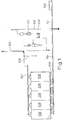
- the silo zone shown in FIG. 1 represents the mill entrance.
- Grain to be ground for example wheat
- the grain is transferred from the goods receipt zone 1 00 to a conveyor system 101, for example a chain transporter.
- the chain transporter conveys the wheat to a height conveyor 102, also called an elevator.
- the height conveyor 102 conveys the grain up several floors within a mill system.
- the grain is then passed through a scale 103.
- the amount of wheat introduced into the grain mill system is measured in the balance 103.
- the ground material flow leads to a cleaning, separating and sieving device 104. In this device, the wheat is first cleaned.
- the wheat is roughly separated from foreign elements, for example by rotating sieves.
- the wheat After passing through the cleaning, separating and screening device 104, the wheat is fed to a further height conveyor 105, which lifts the wheat and feeds it to a further conveyor system 107.
- the conveyor system 107 guides the wheat into one or more input silos 108 arranged in sequence. In the exemplary embodiment shown, five input silos 108 are shown. Each silo has a capacity of approx. 300 t.
- the conveyor system 107 is designed such that a batch of wheat can be introduced into a predetermined input silo 108 with it. By means of the conveyor system 107, different filling quantities of the same wheat or similar types of wheat can accordingly be entered into different silos, each intended for this purpose.
- Suitable silo outlets 109 on the bottom of the silos 108 open when activated accordingly.
- the wheat can optionally be drawn off from the individual silos 108 and run out onto a further conveyor system 110, for example, again a chain transporter.
- the conveyor system 110 conveys the wheat to the height conveyor 102 again. After leaving the height conveyor 102, the rock again passes through the scale 103, the cleaning, separating and sieving device 104 and the height conveyor 105. This time, however, the wheat is not fed to the conveyor system 107 but to a further conveyor system 106 or 106 '(see FIG. 2).
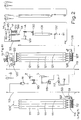
- the wheat arrives in four short-term storage silos 111 via the conveyor system 106, 106 '.
- the term short-term storage silo 111 was chosen because in the short-term storage silos 111 the types and quantities of grain that are required for a desired end product are usually only available for the duration of the grinding of the grain to this end product can be stored in the silos 111.
- the scales 103 also serve to check the weight of the amount of grain removed from the silos 108.
- the weight 103 is used to measure the weight of the amount of grain that is fed to the further grinding process.
- Special silo outlets are provided on the bottom of the short-term storage silos 111, by means of which the silos can be emptied.
- Flow rate control circuits 114 are shown between the silo outlets and a downstream further conveyor system 112, for example a tubular screw conveyor.
- the flow rate control circuits 114 are explained in more detail with reference to FIG. 7.
- the flow rate regulators regulate the wheat supply to the conveyor system 112, which passes into a further height conveyor 113.
- a desired wheat mixture can also be fed to the conveyor system 112 by means of the flow rate control if different types of wheat or cereals are stored in the short-term storage 111.
- Elevator 113 conveys the wheat up to the top floor of a grain mill system. From there, the wheat first arrives at a scale W. After passing through the scale, the wheat is fed to a further cleaning, separating and sieving device 115 known per se, wherein the device 115 can also be equipped with a so-called intermediate separator Z.
- the wheat After passing through the cleaning, separating and screening device 115, the wheat passes through a stone reader 116.
- the stone reader 116 is also known per se. It is used to remove stones or similar foreign bodies from the dry grain.
- an air cleaning device L is also assigned to the dry stone reader 116, which preferably cleans the dust air via pneumatically operated filters.
- trimmer 117 After passing through the stone reader 116, the grain arrives at a so-called trimmer 117, known per se, which removes seeds and other plant parts or similar foreign bodies from the grain. After passing through the drive 117, the wheat is essentially in pure form.
- the now cleaned wheat arrives via a further height conveyor 119 into a wetting zone 120 and from there into resting cells 121 underneath.
- the wetting zone 120 has a control circuit 123 for wetting. This control loop is explained in more detail in FIG. 8.
- the term wetting means moistening the grain.
- the moisture content of the dry wheat is first measured in the wetting zone 120. Based on this measurement result, the amount of water required for the further conditioning of the wheat is calculated. It is known that the best way to process wheat in a grain mill system is if it has a moisture content that - depending on the type of grain - is between 16 and 17%. In the wetting zone, the water is added to the grain in a wetting device 122.
- the wheat After passing through the power supply 122, the wheat arrives in the stand-off cells 121. he lingers for a while in the rest cells with the water supplied to him. The standby time is chosen so that the amount of water added for the required moisture is practically completely absorbed by the wheat. The wheat is then released from the bottom of the stand-off cells 121.
- Flow rate control circuits 126 are again used for this purpose. These control loops 126 can be constructed in the same way as the flow rate control loops 114.
- the grain passes from the flow rate control circuits 126 to a further conveying device 127, for example a tubular screw conveyor, and from there to a height conveyor 128.
- a further conveying device 127 for example a tubular screw conveyor, and from there to a height conveyor 128.
- the wetting and standing process can also be repeated if the desired moisture between 16 and 17% cannot be reached by wetting and standing once.
- the flow rate control circuits 126 form a further possibility of mixing different types of wheat with one another, the individual types of wheat each having the same moisture content.
- the amount of water to be added to the wheat depends on the initial moisture content of the wheat to be processed. If the wheat comes from a hot dry climate, more moisture needs to be added to get the desired moisture content. In this case, the double wetting and standing treatment mentioned above can be carried out. If, on the other hand, the wheat or the grain has a higher moisture content, a single wetting with subsequent standing is sufficient.
- Elevator 128 conveys the wheat a scouring machine 129 which scrubs the surface of the wheat grains in a manner known per se.
- the wheat is then fed to a surface wetting device 130, which is designed in a manner known per se for wetting the wheat surface with water. This increases the moisture content of the surface of the wheat grain husk.
- the wheat is then called a depot upstream of the roller mill B, hereinafter also called depot B, or depot 131, ie it is fed to a further silo.
- depot B the wheat remains for a relatively short time, for example 30 or more minutes.
- the moisture adhering to the surface of the wheat grains penetrates a little into the skin; the wheat swells. This process is also known per se.
- the wheat is fed to a scale 132, which feeds it to the next stage, ie the roller mill or the roller mill B.
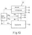
- the flow rate control loops 114 and 126 in the wetting and stand-off zone can be controlled by a common storage unit 42, optionally with an upstream master computer 40.
- An example of such a circuit is shown in FIG. 11.
- the control loops 114, 123 and 126 for the flow rate control or for the wetting can be designed such that only one actual value sensor and one actuator is present on the respective machines, while all other parts of the control loops or control chains are integrated in the master computer 40 with memory unit 42 are.
- a line P for recording protocols also emanates from the master computer 40, including memory 42.
- an input control line St i is also provided, which gives control signals to the host computer. Control signals of this type can, for example, originate from the measuring devices 45, which monitor target variables or from sensors of other parameters.
- the output line Sto outputs control signals to locking elements and / or adjusting means for setting operational signals.
- Pneumatic lines are also provided on the right in FIG.
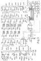
- FIG 3 shows a mill diagram for the zone of grinding and extraction of the products by screening. Wheat coming from depot B, 131 is first fed to roller mill 200 or B, respectively.
- FIG. 5 shows a simplified section from FIG. 3 in the form of a flow diagram, the section having six roller mills B "B 2 , B 3 , e" C 2 , C 3 , six classifiers and two grit cleaning machines; 5 is used for a better understanding of FIG. 2.
- the section shown in FIG. 5 has three crushing roller mills 140, 141 and 142 together with associated sifters 143, 144 and 145.
- the rollers of the crushing roller mills are called crushing rollers because they break the grain.
- the crushing rollers have a corrugated surface. That is why they are also called corrugated rollers.
- plan sifters can be used as sifters.
- three grinding roller mills 146, 147 and 148 with associated sifters 149, 150 and 151 are provided.
- the rollers of the grinding roller mills have a smooth surface; they are therefore also called smooth rolls.
- Two grout cleaning machines 152 and 153 are arranged between the crushing rollers and the smooth rollers.
- roller mills, classifiers and grit cleaning machines are known per se. According to the invention, however, their adjustment means are designed such that they can be controlled by the controllers 50, 50a, 50b, 50c and 50d symbolized in FIG. 3. They therefore represent actuators within a control loop. This will be dealt with in more detail, for example using the description of FIG. 11.
- the material to be ground passes from the balance 132 (FIG. 2) to the first crushing rollers 140 and from there to the sifter 143.
- the sifter 143 has two sieves, namely a first sieve 154 with approximately 30 wires per inch and a second screen 155 with a mesh size of about 150 microns.
- the outputs 156, 157 and 158 of the screens 154 and 155 therefore give the so-called repulsion, i.e. the part that does not fall through the sieve (exit 156), semolina (exit 157) and flour (exit 158).
- the flour coming out of the sieve outlet 158 is fed via an outlet line 159 to a container B ", for example another silo.
- the discharge given off from the sieve outlet 156 is fed to the next crushing rollers 141.
- the semolina discharged from the sieve outlet 157 is fed to the semolina cleaning machine 152 cleaned, for example by aspiration, the wheat kernels and shell parts being fed to the outlet 161 and the semolina to the outlet 160.
- the parts fed to the outlet 161 are then fed to the next crushing rollers 141 together with the push-off at the outlet 156 of the classifier 143. This at the outlet 160 pending pure semolina is fed to the first pair of smooth rollers 146.
- the material ground in the crushing rollers 141 is in turn fed to a classifier, namely the classifier 144, which has a first screen 162 of approximately 36 wires per inch or inch and a second screen 163 of approximately 132 microns in mesh size.
- the sifter 144 has an exit 164 for the kick, an exit 165 for the semolina and an exit 166 for the end product flour.
- the flour present at the sieve outlet 166 is fed to an outlet line 167 and fed into an end product container, for example a silo B 2 , for the regrind coming from B 2 .
- the repulsion pending at the exit 164 becomes the last crushing roller pair 142 shown in FIG. 5 fed.
- the semolina present at the exit 165 is fed to the second semolina cleaning machine 153.
- the outlet 168 there is pure semolina, which is fed to the second pair of smooth rollers 146.
- the exit 169 of the grit cleaning machine 153 or S2 shell parts and remaining parts are in turn, which are fed to the last crushing roller mill 142.
- the material ground in the last pair of crushing rollers 142 is fed to the sifter 145; the sifter 145 has a first screen 170 with approximately forty wires or meshes per inch or inch and a second screen 171 with a mesh size of approximately 132 ⁇ m.
- the classifier 145 is equipped with an output 172, from which the repulsion is fed to an output line 173. Via the output line 173, the shell residues or the bran are again fed to a container provided for this purpose, for example in turn to a silo.
- the classifier 145 is also equipped with a further output 174 for semolina, which is fed to the second classifier 153.
- the end product flour is present at the exit 175 of the classifier 145 and is fed via the outlet line 176 to a silo which receives the flour ground by B 3 and is therefore called silo B 3 .
- the product ground in the pair of smooth rollers 146 reaches the sifter 149, which has two screening stages 177. Sieve stages 177 work in parallel and have a mesh size of approximately 150 flm.
- the classifier 149 is equipped with outputs 178 and 179. At the exit 178 there is the screen rejection which is fed to the next pair of smooth rollers 147. Flour is present at outlet 179, which is fed via an outlet line 180 to a container for the end product flour. This container is e.g. a silo C,.
- the classifier 149 also has a coarse screen 181 which has approximately 40 meshes per inch. The rejection of this coarse screen 181 is fed to the last sifter 151.
- the coarse sieve 181 essentially consists of shell parts. It can also contain a little flour, which is separated by means of the last classifier 151.
- the regrind from the second pair of smooth rollers 147 is fed to the sifter 150, which also has two sieves 182.
- the sieves 182 have a mesh size of approximately 132 ⁇ m and work in parallel. Both screens 182 are repelled at exit 183; from there it reaches the last pair of smooth rollers 148.
- Flour which is present at the exit 184 of the classifier 150, passes through an outlet line 185 into a corresponding container.
- the classifier 150 also has a preliminary or coarse screen 186 with approximately fifty meshes per inch or inch. The rejection of the coarse screen 186 also reaches the last classifier 151.
- the material emanating from the last smooth rollers 148 is fed to the classifier 151, which likewise has two screens 187 working in parallel. Each of these two screens has a mesh size of approximately 132 f lm. The repulsion of these sieves passes through the outlet 188 and the outlet line 189 into a container for fine bran.
- the flour obtained in the sifter 151 reaches a flour silo via the outlet 190 and the outlet line 191. From the above description it is apparent that the unmilled grain arriving at the first pair of crushing rollers 141 is successively broken, sifted and cleaned in order to obtain several flour qualities at the exits 159, 167, 176, 180, 185 and 191. These flour qualities are referred to in FIG.
- the flour is separated from the shell parts which are discharged through the output lines 173 and 189.
- the number of roller mills, classifiers and grout cleaning machines is usually considerably higher. This number depends on the one hand on the type of grain to be processed and the grain mill system used for this. Furthermore, the number depends on the amount of ground material to be processed and the desired end product.
- the exemplary embodiment shown in FIG. 3 for the grinding zone has considerably more roller mills, classifiers and semolina cleaning machines, namely up to 20 cylinder mills 200, up to twenty classifiers 201 and up to ten semolina cleaning machines 202.
- the controllers 50, 50a, 50b, 50c and 50d shown in FIG. 3, together with assigned switches 27, setpoint transmitters 52 and actual value feedback lines S, are explained in more detail with reference to FIGS. 1.6 to 9 and 11.
- the individual controllers 50, 50a, 50b, 50c, 50d can also be located in the grinding zone within the second level mentioned at the beginning or in the third level, i.e. be summarized in the host computer.
- the combination of the controllers is preferably designed so that only the actual value sensor and the actuator or the servomotor are provided on the machine parts to be controlled.
- the rest of the control loops are in a common module, be it on the second level or on the third level, i.e. in the host computer, summarized and integrated if necessary. However, the summary is preferably designed so that each machine part can be controlled individually.
- the control of the roller mills preferably takes place via the roller adjusting means known per se, which, however, are changed compared to the known adjusting means insofar as they can be controlled by control signals.
- the module in which the controllers or parts thereof are combined is symbolized by block 500 in master computer 40 with memory 42. However, it is not absolutely necessary that a controller is assigned to each of the roller mills and / or that all controllers are integrated in module 500. It is often sufficient to regulate only a certain number of roller mills.
- the conventional control or locking means which lock the individual machine parts together, can also be integrated in the master computer 40 insofar as the commands ON / OFF etc. originate from there.
- the necessary control signals can be determined for example by means of a data stored in the host computer 40 program.
- the brightness measuring devices 213 are scales 216 downstream whose Messignalaus sau are supplied to a yield calculator 600th the yield computer outputs the actual values as actual values in the control computer, which compares these values with target values for the yield, the feedback lines to the control computer 40 emanating from the brightness measuring devices 213 and the yield computer 600 accordingly lead to constant monitoring of the system
- the master computer can assign a specific setting of the operational process parameters within the grinding zone - taking into account the specified final parameter values for quality, yield, etc. These assignments can be printed out, for example, via a protocol line P, so that an increased transparency of the operation of the grain mill system can be achieved.
- the controller 50 ′′ provided for the flour mixing can also itself be designed as a programmable controller, whereby it outputs manipulated variables for the mixing flaps depending on the measured brightness values of the flours.
- the aforementioned integration of the controller parts, timing chain parts and locking parts in the host computer means that if the actual output variables deviate too much from the target variables, control signals are first used to try to reduce the deviation, an alarm signal is given and / or the mill is switched off.
- the components shown with the reference symbol L essentially serve to purify the air flowing through the mill system.
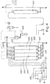
- the part of the mill diagram shown in FIG. 4 of the grain mill system according to the invention serves to store and pack the mill products that were obtained in the grinding and classifying zone according to FIGS. 3 and 5.
- the flour present at the exits of the grinding zone according to FIG. 3 is in three qualities I, II and III and reaches the silo zone according to FIG. 4 in these three qualities.
- the three flour qualities via the lines 218 by means of a pneumatic elevator 219 Group of silos 220 fed for the final products.
- the lines 218 are connected to the pneumatic elevators 219 via air locks 221. Compressed air is fed to the pneumatic elevators via valves 222.
- the three different flour qualities in the three lines 218 can be mixed in different proportions and introduced into the individual silos 220.
- Vibratory discharge funnel 223, i.e. Funnels which are vibrated are provided at the bottom of each silo 220.
- the flour is fed from the vibrating hopper 223 to a conveyor system 224. From there it reaches a further conveyor system 226 via a height conveyor 225.
- flow-rate regulators by means of which a further mixing of the flours is possible, can in principle also be connected downstream of the vibrating outlet funnels 223.
- the flour can either be fed back into the silos, a further mixing effect being possible.
- the flour can also be fed to a constant level container 227, which is known per se.
- the constant level container 227 is upstream of a scale with a packing machine connected downstream.
- the packing machine 228, which is known per se the flour is packed in sacks and made available for transport from the grain mill system.
- the conveyor system 226 can also feed the flour to a further discharge, from which it is filled directly into containers, for example into containers on trucks or railroads. 4, a further silo 229 with associated collecting and conveying lines, height conveyors and further devices for storing bran or other material that falls off in the individual process stages is also provided. This material is fed to silo container 229, for example, via output lines 173 and 189 in FIG. 5. It can be used as animal feed or for other purposes.
- the dashed lines illustrate the possibilities for the upper miller M to intervene in the grain mill system according to the invention.
- the dash-dotted lines illustrate the interactions between the machine park and its control means, including the locking system known per se with the Assembly.
- the solid lines represent the signal flow between the elements of the assembly 30.
- the grain mill system has a machine park 12, the locking unit 14 known per se for controlling the machine park and actuators 16, including servomotors and actuators. These three units are combined as a system plus controller 10.
- the system plus control system 10 comprises the silo tract, the cleaning section and the actual mill.
- the system plus controller 10 can be switched on via the first switches 20 and 26 of the assembly 30. The connection is made by the Obermüller M.
- the assembly 30 has the master computer 40 which controls the memory unit 42, also called the setpoint memory 42.
- the setpoint memory 42 specifies setpoints to the controllers 50 1 to 50 n in accordance with the command from the host computer.
- the controllers 50 to 50 0 intervene in process zones 51 to 51 n .
- the grain mill system according to the invention preferably has three control computers with subordinate components as shown in FIG. 11, one control computer being assigned to exactly one process zone, namely the silo, cleaning and actual mill zone.
- the assembly 30 has a main computer 60 which interacts with two or more master computers including downstream components according to FIG. 11. As soon as the assembly 30 for the mutual flow of information is connected to the system plus controller 10 by actuating the first switches 20 and 26, at least one control loop is established.
- the method area shown in FIG. 11 has the actuators 16 according to the invention and the locking unit 14 known per se.
- the locking unit 14 known per se can be operated directly by the upper miller M. If the top miller M switches on at least one switch 26 and / or 26 n via the intervention line M 3 , then a connection is established between at least one controller 50 1 to 50 n , at least one process zone 51 to n and that of the system controller 16 including the lock 14 produced. This connection creates at least one control loop. For reasons of clarity, the comparator and the control amplifier are not shown separately in FIG. 11.
- each controller for example controller 50 0, receives the nth actual value, determines the control deviation and outputs a corresponding manipulated variable to the system controller 16, including the lock 14. This regulates the controlled variable.
- the controller 50 1 to 50 n can be given the setpoint manually by the top miller M via the line M 4b . Separate setpoint devices are provided for this purpose. Furthermore, second switches 27, to 27 must be switched accordingly by the upper miller M in order to establish a connection between the setpoint generators 52, to 52 n and the corresponding controllers 50, to 50 n .
- the switches 27 to 27 n are switched such that a connection between the controllers 50 1 to 50 n and the setpoint memory 42 is established.
- the command value storage 42 is for each controller 50, 50 to at least one setpoint representative control signal n is stored.
- several setpoints or control signals are stored for each controller 50 to 50 n , the selection of the setpoint to be given to the controller either by appropriate addressing of the memory location by Obermüller M or by addressing by means of one or more measuring devices 45 or by addressing by the Input signal size group is made.
- the measuring devices 45 measure operative process parameters, for example temperature, humidity and / or pressure in the grinding roller gap, and / or target values.
- setpoints or control signals are controlled in the setpoint memory 42 by the outputs of the measuring devices 45, which Obermüller M had previously stored as optimal under the given process conditions.
- Such optimal values are stored, for example, in that the upper miller M first regulates the controlled variables by hand until he obtains optimal results and then outputs these results as setpoints for the further process in the setpoint memory 42.
- the lines S 1 and S n are provided for this purpose.
- the actual value optimally set by the Obermüller thus becomes the new setpoint or a new control signal after being stored in the setpoint memory 42.
- the master computer 40 is connected upstream of the setpoint memory 42.
- the master computer 40 is designed in such a way that, when specifying or entering process variables, for example grain type, grain type, grain mixture and / or desired end product, etc., it addresses the storage locations in the setpoint memory 42 that match this and thereby a setpoint specification for the controllers 50 corresponding to these storage locations 1 to 50 n causes.
- the master computer 40 must also first receive from Obermüller M the input signal variables which are assigned to the predetermined process variables just mentioned. From these input signal quantities, he formulates the address signals for the corresponding control signal representative setpoint values.
- connection of the master computer 40 in front of the setpoint memory 42 has the advantage that the upper miller M is made easier to adjust the mill system at a later point in time if the same or similar predetermined process variables are available.
- the Obermüller M only has to have the corresponding On gave the master computer 40, whereupon the latter then automatically selects the correlated target values.
- the measuring devices 45 can also first control the master computer 40 with the measured values for the operational process parameters and / or target values, whereupon the master computer 40 then selects and corrects the corresponding correction target values in the target value memory 42 their output as setpoint values for the controllers 50 to 50 n .
- setpoint diagram in the setpoint memory i.e. symbolizes a control signal group, with for example each group being assigned a group of input signal quantities and each column being assigned a group of control signals (setpoints).
- a control signal group i.e. symbolizes a control signal group, with for example each group being assigned a group of input signal quantities and each column being assigned a group of control signals (setpoints).
- Such a scheme can be implemented, for example, by a punch card.
- a connection AS is also provided between the system controller 16, including the lock 14 and the setpoint memory 42.
- the setpoint memory 42 can be directly addressed via this line AS, for example as a function of the respective process status of the grinding process. This applies in particular to the start-up and phase-out phase. As a result, the target value memory 42 can be given specific target values that are separate for these phases.
- These setpoints are then so-called command variables, since they are at least presented as functions that change over time.
- the above-mentioned feedback between the setpoint memory 42 and the system control, including the lock 14, also serves in the event of an emergency that might occur, which would require the module to be switched off immediately.
- the feedback AR between the controllers 50 1 to 50 n and the system controller 16, including the lock 14, serves the same purpose.
- the switch 26 a is used to switch from manual to automatic via the access M z . 3 '
- the connecting line AV is provided in a manner known per se.
- the upper miller M has direct access to all components, so that he can intervene at any time in a controlling manner.
- the exemplary embodiment shown schematically in FIG. 12 differs essentially from the exemplary embodiment according to FIG. 11 in that a main computer 60 is superordinate to the master computer (s) 40.
- the main computer 60 can also be connected to the process areas 30 a to 30 n via third switches 62 1 to 62 n . These switches are also accessible for direct access by the upper miller M.
- the main computer 60 can also be operated by the Obermüller M via an ON / OFF switch 63.
- the output variables of the measuring devices 45 for the process variables are fed to the main computer 60.
- the latter processes the values supplied to it for forwarding to the master computer 40, controlling the setpoint memories 42 and controlling the control chains and / or control loops.
- the embodiment according to FIG. 13 essentially differs from the embodiment shown in FIG. 12 in that the main computer with the system control and interlocking is integrated to form a unit 70.
- control computers with setpoint memories are connected upstream of the regulators and / or control elements, the control computers being designed for the selection and / or correction of individual setpoints (groups) or control characteristics.
- a control computer with a setpoint accumulator is provided for each of the silo section, the cleaning section and the mill.
- main computers are preceded by a main computer which, for example, specifies weekly programs, monthly programs, etc.
- the main computer, the control computer and / or the collective memory can be connected to the outputs of the measuring devices for operational process parameters, specifically for the selection and / or correction of setpoint values or control signals.
- the hierarchical levels are all connected to one another via switches which can be actuated by the Obermüller M. It is also important that the hierarchical levels are fed back to one another in such a way that in the event of an error in one of the levels, the next lower level is automatically decoupled from the higher level. This point of view applies not only to the levels as a whole, but also to individual sections or control loops within or between the levels.
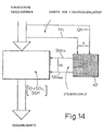
- FIGS. 14 and 15 illustrate schematic flow diagrams of the process control or an exemplary embodiment for a matrix-based storage unit 42.
- a group of selected process variables is evaluated quantitatively and qualitatively and supplied to the memory unit 42 as a group of input signal variables Q 1 M 1 , ..., Q n M n .
- This group of input signal quantities serves as an address signal for addressing or selecting control signals St o11 ,... St o1n previously stored in the memory unit 42.
- the control signals correspond to the setpoints in the control loops or a predetermined change in the control characteristic of timing chains.
- the control chains and / or control loops are designed to influence operational process parameters that can be directly assigned to the process elements.
- the storage unit 42 is designed as a three-dimensional matrix-shaped storage unit.
- qualitative and quantitative evaluations of the predetermined cereal mixtures M 1 ' M z and M; 3 and the quality of the mixture or of the mixture proportions 0 1 , Q 2 and Q 3 are provided as input signal variables.
- the input signal size group M 1 , Q 1 is assigned to a control signal size group St o11 , .., St o1n provided in a vertical column. This control signal size group then influences the operational process parameters.
- the input signal quantities Q 1 to Q 3 can also be target quantities for desired flour qualities.
- the table below shows an example of an assignment between some predefined process variables (input signal variables) and some operational process parameters (control signals or memory data).
- the table is only an illustration and does not claim to be complete.
- FIG. 9 shows an exemplary embodiment of the arrangement shown in FIG. 3 for the automatic mixing of the passage flours with three flour qualities on an enlarged scale.
- the passage flours are supplied via flow slide valves 210 via the output lines 159, 167, 176, 180, 185 and 191 (cf. FIG. 5).
- the slide valves are designed as three-way control valves in such a way that the incoming passage flours are directed in three different directions and can be fed to the three conveyor systems 211.
- the conveyor systems 211 are preferably designed as tubular screw conveyors. As a result, the supplied portions of the passage flours are mixed. Accordingly, by appropriately actuating the slide valves 210, different mixture proportions can be supplied to the three delivery systems 211.
- the conveyor systems 211 are preferably subjected to vibration, which leads to better mixing.
- the brightness measuring devices 213 already mentioned are arranged downstream of the outputs 212 of the conveyor systems 211.
- the output signal quantities of the measuring devices 213 are recorded within the electronic circuits 214 and supplied in the form of electrical signals via the lines 215 shown in FIG. 3 to the controller 50 n provided for the mixing and / or the master computer 40.
- the controller 50 n and / or the master computer determine by comparison the deviation of the actual brightness signal from the target variable or the target value for the flour brightness and emit a corresponding manipulated variable signal to the mixing flaps of the flow slide valves.
- the control computer 40 which in turn makes a comparison between the target size and the actual yield of white flour and, depending on the comparison result, outputs control signals to the slide valves.
- the master computer is designed in such a way that, in the event of major deviations in the actual yield from the desired yield, it influences the grinding roller setting via control signals, emits an alarm and / or the locking device switches off the mill or parts of the mill.
- FIG. 6 A further exemplary embodiment for the control of an operational process parameter, namely the roll gap, is shown in FIG. 6, the roll gap itself being subjected to regulation by means of a control loop, but the controller of the control loop being controlled.
- 6 shows a pair of rolls designed as a roll set.
- the pair of rollers shown has a right grinding roller 230 and a left grinding roller 230 '.
- the grinding rollers are rotatably supported in roller housings 232 and 233.
- the roller housings in turn are fastened to a tie rod 234 via bolts 235, 235 '.
- the attachment is carried out in such a way that the right grinding roller 230 can be pivoted within the housing assigned to it relative to the left grinding roller 230 '. This pivotability enables the roll gap to be changed.
- the left grinding roller 230 ' is held in an upright position by a pin 231 provided in addition to the pin 235'.
- the two bearing housings 232 and 233 are mutually adjustable by means of a guide spindle 236. Rotation of the lead screw 236 changes the nip.
- an electric servo motor 238 is provided, which serves as an actuator and acts on the guide spindle 236 via a suitable reduction gear.
- a servo amplifier is connected upstream of the servo motor.
- the servo motor 238 acts as an actuator in the control loop to be described. Further
- a handwheel 239 is provided, with the aid of which the guide spindle 236 can also be rotated - likewise via a corresponding reduction gear.
- the roller spacing is accordingly adjustable by handwheel 239 from Obermüller or by servo motor 238.
- a proximity switch consisting of the transmitting part 240 and receiving part 241, is arranged at the upper end of the bearing housing 232, 233. This proximity switch emits an electrical signal which corresponds to the distance between its transmitter 240 and its receiver 241. Since the proximity switch 240, 241 is firmly connected to the bearing housings 232, 233, this corresponds to signal emitted by the proximity switch simultaneously the distance between the two rollers.
- Proximity switch 240, 241 which is designed as a transmitter and receiver, can also be replaced by another suitable proximity measuring device.
- the controller 50 already shown in the figures described above comprises a comparator or comparator for a comparison between the actual value and the setpoint, a downstream signal amplifier and a converter for emitting a suitable manipulated variable, i.e. a suitable signal for controlling the servo or servo motor 238.
- the controller output is fed to the servo motor 238 via the line 24.
- the servo motor can be uncoupled from the controller 50 by means of the switch 26 already described, for example for the purpose of a desired manual setting of the grinding roller gap using the handwheel 239.
- the signal emanating from the proximity switch 240, 241 is fed as an actual value via line 57 to the controller input.
- the comparator it is then compared with a setpoint which is given to controller 50 via line 53 (cf. FIG. 11).
- the setpoint can be adjusted manually via input M4b. However, it can also be specified by the memory unit or a collective data memory for setpoints 42 when the switch 27 is closed.
- the setpoint generator 52 can therefore be controlled directly by the top miller.
- the setpoint generator 52 can be controlled by the memory unit 42.
- the memory unit 42 is connected upstream of the master computer 40 for automatic setpoint specification.
- the values determined by quantitative and qualitative evaluation of the predetermined mixture and quality are input to this master computer 40 as input signal quantities. This group of input signals then serves as an address signal for the setpoint of the roller spacing.
- the storage unit 42 is followed by a series of further regulators 50 for regulating further process parameters, for example further roller nips. Because the use of a memory for controlling only a single process variable within the entire mill system would not be justifiable for economic reasons. Furthermore, the output signals of a temperature measuring device 45 T and a pressure measuring device 45 D can be supplied as address signals. The sensors of these measuring devices are symbolically identified by the reference numerals 242 and 243.
- FIG. 6 also shows the possibility of storing new control signals or signals representative of setpoint values in the storage unit 42.
- the line S 1 (cf. FIG. 11) is provided, which sends the signals from the receiver part 241 of the proximity switch 240, 241 to the master computer 40 feeds. This then writes corresponding setpoint representative control signals into the memory unit 42.
- the top miller can, for example by turning handwheels 239, adjust the nips of several pairs of grinding rollers until he has found optimal values and then write these settings into the storage unit 42 via line 57, S.
- Each pair of rollers shown in Figures 3 and 5 can be equipped with a controller in this way.
- the controllers can then be connected together with the master computer 40 or the storage unit 42.
- the controllers 50 can also be integrated in the master computer, which is particularly advantageous in the case of twenty or more pairs of rollers to be controlled.
- roller pairs are exemplary embodiments for the process zones 51 to 51 n shown in FIG. 11. Further correlations between the exemplary embodiment shown in FIG. 6 and FIG. 11 can be seen in that corresponding parts have been given the same reference numerals.
- the exemplary embodiment mentioned above showed a control loop within the grinding zone.
- FIG. 7 Another exemplary embodiment of a controllable control loop within the cleaning zone is illustrated with reference to FIG. 7.
- the regulation carried out here relates to the flow quantity regulation, which has already been addressed in FIG. 2.
- Each flow rate control circuit 114 here has a pivotably arranged plate 250 which is elastically biased against an angular deflection.
- the grain flow impinging on plate 250 exerts a torque on plate 250.
- the angle of rotation corresponds to the grain flow rate.
- the angular deflection of plate 250 is converted into an electrical signal and fed to controller 50 via line 57.
- the controller 50 receives a setpoint signal via the line 53, which is specified by the memory unit 42 in the position of the switch 27 shown. In the other position of the switch 27, the setpoint signal is set by the setpoint generator 52.
- the line S leads to the memory unit 42, possibly via the master computer 40, and is used to write new control signals representative of setpoint values into the memory unit 42.
- any desired grain mixture can be fed to the conveyor system 112 by specifying corresponding setpoints.
- the controllers are also integrated in a common module, this integration being able to be carried out both at the second level, that is to say the control loop level, or also at the third level, in this case in the host computer.
- the switch 27 gives the option of switching off the second level, ie the control loop level from the third level, ie from the host computer and the storage unit.
- a switch corresponding to the switch 26 in FIG. 11 between the controller 50 and the control means the flow rate control loop would enable the decoupling of the second level from the first level.
- FIG. 2 A further exemplary embodiment of the control of a grain mill system according to the invention is represented by the regulation or control of the grain moisture shown in FIG. 8.
- FIG. 2 is used here.
- the grain to be moistened is first passed through a moisture measuring device 260.
- the moisture measuring device 260 emits an electrical signal via the line 261 which corresponds to the moisture content of the grain supplied.
- the amount of water that is required to achieve the desired moisture content is calculated. This calculation is carried out either in a local, permanently programmed computer 263 provided for this purpose, or, for example, in the host computer 40.
- the moistening, ie the wetting of the grain takes place in the power supply unit 12.
- the amount of water required can be specified, for example, as a setpoint for a water flow rate controller. If the calculation is carried out in the control computer 40, the switch 27 2 is switched to the position shown in FIG. 8. If the setpoint for the water flow rate is to be predetermined by manual testing, then the switch 27 z is switched to the lower, dashed position. If the target value for the water flow rate is determined by the local computer 263, the switch 27 z is in the middle position. When calculating the setpoint for the water flow rate, the flow rate of the grain is usually also taken into account. The controller 50 2 is provided to regulate the water flow rate. This controller is given the setpoints via line 53 z . The controller receives the actual value via line 57 2 .
- the actual value line ends at a measuring device within a valve 264 for controlling the flow rate.
- the error signal is determined in the controller 50 2 by comparison between the actual value and the target value, and the manipulated variable is derived from this error signal, which is fed to the control valve 264 via the line 266.
- line S 2 is again provided, which is connected to a corresponding write input of memory unit 42 or to master computer 40. Via the line S 2 , a flow rate value can be written into the memory which is representative of an optimal water flow.
- the control valve 264 for controlling the water flow rate can also be controlled by hand, so that the top miller can intervene directly in the lowest level of the hierarchical structure. Accordingly, the water flow rate can also be controlled both from the first level, from the second level and from the third level, if appropriate also from the fourth level.
- the parameters mentioned in the introduction to the description for example the relative humidity and the temperature - in addition to further input signal variables, for example quantitative and qualitative values which are assigned to the type of grain, the grain quality, etc. -, are used as address signals for addressing a corresponding setpoint representative control signal in the memory unit 42.
- the address inputs of the memory unit or of the master computer can be provided with visual displays, so that the top miller can always control which process elements he assigns control signals and which process variables he started with.
- a writing device or protocol device can be connected to the master computer, which writes down the input variables, the control signals and the output variables obtained. This measure serves the further transparency of the management of a grain mill plant.
- the memories are preferably designed as digital memories, with correspondingly digitized input variables being specified and digitized control signals being output from the memory.
- a clock is suitable for checking the states of the individual process elements in the above sense, by means of which the individual process elements are cyclically queried for compliance with states or process parameters.
Claims (31)
Applications Claiming Priority (2)
| Application Number | Priority Date | Filing Date | Title |
|---|---|---|---|
| DE2855715A DE2855715C3 (de) | 1978-12-22 | 1978-12-22 | Getreidemühlenanlage zur Herstellung von Mehl |
| DE2855715 | 1978-12-22 |
Publications (2)
| Publication Number | Publication Date |
|---|---|
| EP0013023A1 EP0013023A1 (fr) | 1980-07-09 |
| EP0013023B1 true EP0013023B1 (fr) | 1982-10-20 |
Family
ID=6058138
Family Applications (1)
| Application Number | Title | Priority Date | Filing Date |
|---|---|---|---|
| EP79105351A Expired EP0013023B1 (fr) | 1978-12-22 | 1979-12-22 | Procédé et installation pour la mouture de céréales |
Country Status (11)
| Country | Link |
|---|---|
| US (1) | US4363448A (fr) |
| EP (1) | EP0013023B1 (fr) |
| JP (1) | JPS55116448A (fr) |
| BR (1) | BR7908507A (fr) |
| DD (1) | DD148304A5 (fr) |
| DE (2) | DE2855715C3 (fr) |
| ES (1) | ES487229A0 (fr) |
| GB (2) | GB2044481B (fr) |
| PL (1) | PL132265B1 (fr) |
| SU (1) | SU1340574A3 (fr) |
| ZA (1) | ZA797034B (fr) |
Cited By (4)
| Publication number | Priority date | Publication date | Assignee | Title |
|---|---|---|---|---|
| WO2010000816A1 (fr) * | 2008-07-02 | 2010-01-07 | Bühler AG | Système de régulation pour une installation de transformation de céréales |
| WO2013135308A1 (fr) * | 2012-03-16 | 2013-09-19 | Bühler AG | Dispositif et procédé pour un processus optimisé de mouture de céréales, ainsi que produit de programme par ordinateur correspondant pour la commande du dispositif |
| CN107861540A (zh) * | 2017-11-16 | 2018-03-30 | 常德科祥机电制造有限公司 | 一种谷物烘干机自动控制装置及其控制方法 |
| WO2019101968A1 (fr) | 2017-11-23 | 2019-05-31 | Bühler AG | Dispositif de commande intelligent auto-adaptatif pour l'optimisation et la commande automatisées de la ligne de mouture d'un système de cylindres et procédé correspondant |
Families Citing this family (21)
| Publication number | Priority date | Publication date | Assignee | Title |
|---|---|---|---|---|
| JPS60216844A (ja) * | 1984-04-13 | 1985-10-30 | Nippon Shokubai Kagaku Kogyo Co Ltd | エチレンオキシド製造用銀触媒 |
| WO1986001128A1 (fr) * | 1984-08-03 | 1986-02-27 | Gebrüder Bühler Ag | Dispositif de reglage de l'ecartement de mouture pour moulins a cylindres |
| US4881689A (en) * | 1985-03-15 | 1989-11-21 | Gebrueder Buehler Ag | Method for setting the grinding rollers in roller frames of a flour milling plant, as well as flour milling plant for performing the method |
| AT389653B (de) * | 1985-09-10 | 1990-01-10 | Schroedl Hermann | Verfahren zur einstellung der spaltweite eines kegelbrechers od.dgl. |
| EP0433498B1 (fr) * | 1989-12-13 | 1994-10-05 | Satake Engineering Co., Ltd. | Appareil de broyage et système à cet effet |
| DE4129898C2 (de) * | 1991-09-09 | 1994-10-13 | Graef Dieter Otto | Verfahren zum Vermahlen von Körnerfrüchten sowie Vorrichtung zur Durchführung des Verfahrens |
| FR2685222A1 (fr) * | 1991-12-23 | 1993-06-25 | Framatome Sa | Procede de traitement de grains vegetaux ou de graines vegetales et produits obtenus par ce procede. |
| FR2685223A1 (fr) * | 1991-12-23 | 1993-06-25 | Framatome Sa | Installation de traitement de grains vegetaux ou de graines vegetales. |
| CA2065506C (fr) * | 1992-04-07 | 1997-05-27 | Richard Nolin | Methode et appareil de fragmentation de blocs de matiere vegetale geles |
| IT1288157B1 (it) * | 1996-05-03 | 1998-09-11 | Golfetto Spa | Procedimento per effettuare il controllo automatico della macinazione in un impianto molitorio ed impianto per effettuare il procedimento. |
| US20050004682A1 (en) * | 2003-07-01 | 2005-01-06 | Deere & Company, A Delaware Corporation. | Computer-assisted management of the processing of an agricultural product |
| US20040258807A1 (en) * | 2003-06-20 | 2004-12-23 | Deere & Company, A Delaware Corporation | Method and system for management of the processing of agricultural products |
| DE10344040A1 (de) * | 2003-09-23 | 2005-04-14 | Polysius Ag | Verfahren und Vorrichtung zur Herstellung eines hydraulischen Bindemittels |
| US20070170291A1 (en) * | 2006-01-23 | 2007-07-26 | Naganawa Mauro M | Cracking mill for grains of soy, wheat, and others |
| US20080171114A1 (en) * | 2006-12-20 | 2008-07-17 | Castillo Rodriguez Francisco B | Process for the production of refined whole-wheat flour with low coloration |
| DE102007002243A1 (de) | 2007-01-10 | 2008-07-17 | Bühler AG | Verfahren zum Betreiben einer Anlage |
| WO2014187799A1 (fr) * | 2013-05-22 | 2014-11-27 | Bühler AG | Dispositif et procédé permettant d'optimiser la mouture de céréales ainsi que système de commande de moulins correspondant |
| US10646877B2 (en) * | 2017-03-13 | 2020-05-12 | General Electric Technology Gmbh | System and method for adjusting a material bed depth in a pulverizer mill |
| CN112236233B (zh) * | 2018-05-25 | 2022-03-11 | 布勒有限公司 | 谷物碾磨机和具有用于研磨物优化研磨的多个研磨通道的辊磨机以及对应的方法 |
| BR102021003370B1 (pt) * | 2021-02-23 | 2022-04-05 | Bunge Alimentos S/A | Sistema e método de quebra de grãos |
| CN116159672B (zh) * | 2023-03-01 | 2024-01-05 | 湖南中科电气股份有限公司 | 一种基于石墨化材料分选的磁选系统 |
Family Cites Families (4)
| Publication number | Priority date | Publication date | Assignee | Title |
|---|---|---|---|---|
| US2713460A (en) * | 1952-02-28 | 1955-07-19 | Atkinson Milling Company | Method for regulating pressures on milling rolls |
| US2847167A (en) * | 1954-12-16 | 1958-08-12 | Gen Mills Inc | Milling process for wheat and similar granular food products |
| GB1415604A (en) * | 1973-03-23 | 1975-11-26 | Simon Ltd Henry | Cereal milling |
| CH619157A5 (fr) * | 1976-07-16 | 1980-09-15 | Buehler Ag Geb |
-
1978
- 1978-12-22 DE DE2855715A patent/DE2855715C3/de not_active Expired
-
1979
- 1979-12-19 GB GB7943640A patent/GB2044481B/en not_active Expired
- 1979-12-21 SU SU792861257A patent/SU1340574A3/ru active
- 1979-12-22 JP JP16746579A patent/JPS55116448A/ja active Granted
- 1979-12-22 ES ES487229A patent/ES487229A0/es active Granted
- 1979-12-22 DE DE7979105351T patent/DE2963911D1/de not_active Expired
- 1979-12-22 DD DD79218171A patent/DD148304A5/de unknown
- 1979-12-22 PL PL1979220703A patent/PL132265B1/pl unknown
- 1979-12-22 EP EP79105351A patent/EP0013023B1/fr not_active Expired
- 1979-12-26 BR BR7908507A patent/BR7908507A/pt unknown
- 1979-12-26 US US06/106,939 patent/US4363448A/en not_active Expired - Lifetime
- 1979-12-27 ZA ZA00797034A patent/ZA797034B/xx unknown
-
1982
- 1982-07-08 GB GB08219777A patent/GB2111721B/en not_active Expired
Cited By (4)
| Publication number | Priority date | Publication date | Assignee | Title |
|---|---|---|---|---|
| WO2010000816A1 (fr) * | 2008-07-02 | 2010-01-07 | Bühler AG | Système de régulation pour une installation de transformation de céréales |
| WO2013135308A1 (fr) * | 2012-03-16 | 2013-09-19 | Bühler AG | Dispositif et procédé pour un processus optimisé de mouture de céréales, ainsi que produit de programme par ordinateur correspondant pour la commande du dispositif |
| CN107861540A (zh) * | 2017-11-16 | 2018-03-30 | 常德科祥机电制造有限公司 | 一种谷物烘干机自动控制装置及其控制方法 |
| WO2019101968A1 (fr) | 2017-11-23 | 2019-05-31 | Bühler AG | Dispositif de commande intelligent auto-adaptatif pour l'optimisation et la commande automatisées de la ligne de mouture d'un système de cylindres et procédé correspondant |
Also Published As
| Publication number | Publication date |
|---|---|
| DE2855715C3 (de) | 1982-05-19 |
| DE2855715B2 (de) | 1981-08-06 |
| GB2111721A (en) | 1983-07-06 |
| JPS55116448A (en) | 1980-09-08 |
| GB2111721B (en) | 1983-11-16 |
| ES8101410A1 (es) | 1980-12-16 |
| PL132265B1 (en) | 1985-02-28 |
| ES487229A0 (es) | 1980-12-16 |
| DE2855715A1 (de) | 1980-06-26 |
| EP0013023A1 (fr) | 1980-07-09 |
| ZA797034B (en) | 1981-08-26 |
| JPS6332504B2 (fr) | 1988-06-30 |
| PL220703A1 (fr) | 1980-10-06 |
| GB2044481B (en) | 1983-07-20 |
| BR7908507A (pt) | 1980-07-22 |
| US4363448A (en) | 1982-12-14 |
| DD148304A5 (de) | 1981-05-20 |
| GB2044481A (en) | 1980-10-15 |
| DE2963911D1 (en) | 1982-11-25 |
| SU1340574A3 (ru) | 1987-09-23 |
Similar Documents
| Publication | Publication Date | Title |
|---|---|---|
| EP0013023B1 (fr) | Procédé et installation pour la mouture de céréales | |
| EP0336939B1 (fr) | Procede de fabrication de l'amidon brut et moulin a amidon | |
| EP1763988B1 (fr) | Procédé de régulation d'un organe de travail d'une récolteuse agricole | |
| EP2313199B1 (fr) | Dispositif et procédé pour produire de la farine et/ou de la semoule | |
| EP3801909A1 (fr) | Broyeur à grains et broyeur à rouleaux comportant plusieurs passages de broyage pour optimiser la mouture du matériau à broyer, et procédé correspondant | |
| WO1992018257A1 (fr) | Procede pour l'amenee d'air pour le nettoyage de gruaux, ainsi que sasseur | |
| DE10218424A1 (de) | Schrotmühle sowie Verfahren zur Zerkleinerung von Mahlgut | |
| DE4005323A1 (de) | Verfahren und mahlanlage zur zweistufigen zerkleinerung von sproedem mahlgut | |
| WO1986005416A1 (fr) | Procede d'ajustement des cylindres broyeurs des moulins a cylindres d'une installation de mouture de cereales, installations de mouture de cereales utilisant ce procede | |
| EP2318142A1 (fr) | Système de régulation pour une installation de transformation de céréales | |
| DE1583773A1 (de) | Steuervorrichtung fuer schnell laufende magnetische Trommel-Separatoren | |
| DE3519625A1 (de) | Verfahren zum einstellen der mahlwalzen bei walzenstuehlen einer getreidemuehlenanlage sowie getreidemuehlenanlage zur durchfuehrung des verfahrens | |
| WO2023212830A1 (fr) | Broyeur autonome et procédé de broyage | |
| DE2943597C2 (de) | Vollernter für Maiskolbenschrot | |
| DD282861A5 (de) | Verfahren und Getreidemühle zur Herstellung von Getreidemahlprodukten | |
| DE102020005104A1 (de) | Verfahren zur zumindest rechnerunterstützten Steuerung einer Prozesskette zur Behandlung landwirtschaftlicher Produkte zu Trocken- und Semitrockenprodukten | |
| CH684742A5 (de) | Verfahren zum Reinigen und Sortieren von Schüttgut. | |
| CH528302A (de) | Laborgetreidemühle | |
| DE3717529A1 (de) | Verfahren und vorrichtung zur bestimmung der fuer deren verarbeitung wichtigen eigenschaftswerte von holzspaenen, natuerlichen fasern oder dergleichen materialien | |
| DD291707B5 (de) | Anlagentechnische Schaltung einer trocken arbeitenden Ruehrweksmuehle | |
| DD275414A1 (de) | Saatgutbereiter fuer getreide und feinsaemereien |
Legal Events
| Date | Code | Title | Description |
|---|---|---|---|
| PUAI | Public reference made under article 153(3) epc to a published international application that has entered the european phase |
Free format text: ORIGINAL CODE: 0009012 |
|
| AK | Designated contracting states |
Designated state(s): BE CH DE FR IT NL SE |
|
| 17P | Request for examination filed |
Effective date: 19810107 |
|
| ITF | It: translation for a ep patent filed |
Owner name: JACOBACCI & PERANI S.P.A. |
|
| GRAA | (expected) grant |
Free format text: ORIGINAL CODE: 0009210 |
|
| AK | Designated contracting states |
Designated state(s): BE CH DE FR IT NL SE |
|
| PG25 | Lapsed in a contracting state [announced via postgrant information from national office to epo] |
Ref country code: NL Effective date: 19821020 Ref country code: BE Effective date: 19821020 |
|
| REF | Corresponds to: |
Ref document number: 2963911 Country of ref document: DE Date of ref document: 19821125 |
|
| NLV1 | Nl: lapsed or annulled due to failure to fulfill the requirements of art. 29p and 29m of the patents act | ||
| REG | Reference to a national code |
Ref country code: CH Ref legal event code: PFA Free format text: BUEHLER AG |
|
| REG | Reference to a national code |
Ref country code: FR Ref legal event code: CD |
|
| ITTA | It: last paid annual fee | ||
| EAL | Se: european patent in force in sweden |
Ref document number: 79105351.5 |
|
| REG | Reference to a national code |
Ref country code: FR Ref legal event code: CL |
|
| PGFP | Annual fee paid to national office [announced via postgrant information from national office to epo] |
Ref country code: SE Payment date: 19961121 Year of fee payment: 18 |
|
| PGFP | Annual fee paid to national office [announced via postgrant information from national office to epo] |
Ref country code: FR Payment date: 19971113 Year of fee payment: 19 |
|
| PG25 | Lapsed in a contracting state [announced via postgrant information from national office to epo] |
Ref country code: SE Free format text: LAPSE BECAUSE OF NON-PAYMENT OF DUE FEES Effective date: 19971223 |
|
| EUG | Se: european patent has lapsed |
Ref document number: 79105351.5 |
|
| PGFP | Annual fee paid to national office [announced via postgrant information from national office to epo] |
Ref country code: CH Payment date: 19981110 Year of fee payment: 20 |
|
| PGFP | Annual fee paid to national office [announced via postgrant information from national office to epo] |
Ref country code: DE Payment date: 19981118 Year of fee payment: 20 |
|
| PG25 | Lapsed in a contracting state [announced via postgrant information from national office to epo] |
Ref country code: FR Free format text: LAPSE BECAUSE OF NON-PAYMENT OF DUE FEES Effective date: 19990831 |
|
| REG | Reference to a national code |
Ref country code: FR Ref legal event code: ST |
|
| PG25 | Lapsed in a contracting state [announced via postgrant information from national office to epo] |
Ref country code: CH Free format text: LAPSE BECAUSE OF EXPIRATION OF PROTECTION Effective date: 19991221 |
|
| REG | Reference to a national code |
Ref country code: CH Ref legal event code: PL |
|
| PLBE | No opposition filed within time limit |
Free format text: ORIGINAL CODE: 0009261 |
|
| STAA | Information on the status of an ep patent application or granted ep patent |
Free format text: STATUS: NO OPPOSITION FILED WITHIN TIME LIMIT |