EP0433498B1 - Appareil de broyage et système à cet effet - Google Patents
Appareil de broyage et système à cet effet Download PDFInfo
- Publication number
- EP0433498B1 EP0433498B1 EP89313019A EP89313019A EP0433498B1 EP 0433498 B1 EP0433498 B1 EP 0433498B1 EP 89313019 A EP89313019 A EP 89313019A EP 89313019 A EP89313019 A EP 89313019A EP 0433498 B1 EP0433498 B1 EP 0433498B1
- Authority
- EP
- European Patent Office
- Prior art keywords
- milling
- milled particles
- milled
- granular material
- roll mill
- Prior art date
- Legal status (The legal status is an assumption and is not a legal conclusion. Google has not performed a legal analysis and makes no representation as to the accuracy of the status listed.)
- Revoked
Links
Images


Classifications
-
- B—PERFORMING OPERATIONS; TRANSPORTING
- B02—CRUSHING, PULVERISING, OR DISINTEGRATING; PREPARATORY TREATMENT OF GRAIN FOR MILLING
- B02C—CRUSHING, PULVERISING, OR DISINTEGRATING IN GENERAL; MILLING GRAIN
- B02C4/00—Crushing or disintegrating by roller mills
- B02C4/28—Details
- B02C4/32—Adjusting, applying pressure to, or controlling the distance between, milling members
-
- B—PERFORMING OPERATIONS; TRANSPORTING
- B02—CRUSHING, PULVERISING, OR DISINTEGRATING; PREPARATORY TREATMENT OF GRAIN FOR MILLING
- B02C—CRUSHING, PULVERISING, OR DISINTEGRATING IN GENERAL; MILLING GRAIN
- B02C9/00—Other milling methods or mills specially adapted for grain
- B02C9/04—Systems or sequences of operations; Plant
Definitions
- the present invention relates to an apparatus for milling or flouring granular material such as wheat or the like, and to a system comprising a plurality of milling apparatus each of which includes a roll mill.
- the granular material In milling operation by which granular material to be milled such as wheat or the like is milled to flour, the granular material is supplied to a roll mill where the granular material is milled. However, the granular material is not milled to powder in a single operation. Specifically, a plurality of roll mills are arranged in series, and are functionally combined with a plurality of sorting units and a plurality of transporting units to obtain milled material of the wheat or the like such as flour, that is, to obtain a product which is milled to a requisite particulate or milling degree.
- WO-A-8605416 for example there is described a mill in which a sieving system is connected downstream of the mill and from which a measurement signal is taken and transmitted to a computer.
- the computer compares the signal with a stored desired value and, if there is a difference, automatically adjusts the grinding roller spacing by means of a control signal and adjustment gears.
- an apparatus for milling granular material comprising: an apparatus for milling granular material comprising a roll mill for milling the granular material into milled particles, the roll mill including a pair of rolls which are rotatably arranged in facing relation to each other, at least one of the pair of rolls being movable toward and away from the other, and gap adjusting means associated with said at least one roll for moving the same toward and away from the other roll to adjust a gap between said pair of rolls thereby adjusting a milling degree of the milled particles, and measuring means arranged downstream of said roll mill and connected to said gap adjusting means, for measuring the milling degree of the milled particles to issue an output signal representative of the milling degree, said gap adjusting means being operative in response to said output signal to adjust said gap, said apparatus for milling granular material being characterized in that: said measuring means is constituted by optical means which detects images of the milled particles passing through a predetermined test zone so as to obtain picture signals from projected areas
- the measuring means for measuring the milling degree of the milled material is associated with the roll mill, and the at least one roll is moved toward and away from the other roll on the basis of the output signal from the output signal from the measuring means such that the gap between the pair of rolls is adjusted.
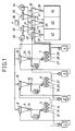
- the milling system comprises main components which include four roll mills or flour mills 1, 2, 3 and 4 connected in series relation to each other and three sieve sorters 5, 6 and 7.
- the milling system comprises three sets of milling apparatus and the fourth roll mill 4.
- Each of the milling apparatuses includes the roll mill 1, 2 or 3 and a measuring device 11, 18 and 26. It is needless to say that the milling system may comprise a pair of roll mills and a pair of sieve sorters.
- the first roll mill 1 communicates with a cyclone 8, by means of pneumatic transportation.
- the cyclone 8 has, at its bottom, an air-lock valve 9.
- a directional control valve 10 arranged downstream of the air-lock valve 9 communicates with the measuring device 11 for measuring a milling degree of milled material such that a part of milled particles is supplied to the measuring device 11.
- the measuring device 11 communicates with a supply port of the first sieve sorter 5.
- the directional control valve 10 also communicates directly with the sieve sorter 5.
- the sieve sorter 5 can sort and separate the milled particles in three stages dependent upon particle size of the milled particles.
- the sieve sorter 5 has a large-particle discharge port 12, an intermediate-particle discharge port 13 and a small-particle discharge port 14.
- the large-particle discharge port 12, the intermediate-particle discharge port 13 and the small-particle discharge port 13 communicate respectively with a supply port of the first roll mill 1, a supply port of the second roll mill 2 and a cyclone 15.
- the second roll mill 2 communicates with the cyclone 15, by means of pneumatic transportation.
- the cyclone 15 has, at its bottom, an air-lock valve 16.
- a directional control valve 17 arranged downstream of the air-lock valve 16 communicates with the measuring device 18 for measuring a milling degree of the milled material such that a part of the milled particles is suitably supplied to the measuring device 18.
- the measuring device 18 communicates with a supply port of the second sieve sorter 6.
- the directional control valve 17 also communicates directly with the sieve sorter 6.
- the sieve sorter 6 can sort and separate the milled particles in three stages dependent upon particle size of the milled particles. Specifically, the sieve sorter 6 has a large-particle discharge port 19, an intermediate-particle discharge port 20 and a small-particle discharge port 21.
- the large-particle discharge port 19, the intermediate-particle discharge port 20 and the small-particle discharge port 21 communicate respectively with the supply port of the second roll mill 2, a supply port of the third roll mill 3 and a cyclone 22.
- the third roll mill 3 communicates with a cyclone 23, by means of pneumatic transportation.
- the cyclone 23 has, its bottom, an air-lock valve 24.
- a directional control valve 25 arranged downstream of the air-lock valve 24 communicates with the measuring device 26 for measuring a milling degree of the milled material such that a part of the milled particles is suitably supplied to the measuring device 26.
- the measuring device 26 communicates with a supply port of the third sieve sorter 7.
- the directional control valve 25 also communicates directly with the third sieve sorter 7.
- the third sieve sorter 7 can sort and separate the milled particles in three stages dependent upon particle size of the milling particles.
- the third sieve sorter 7 has a large-particle discharge port 27, an intermediate-particle discharge port 28 and a small-particle discharge port 29.
- the large-particle discharge port 27, the intermediate-particle discharge port 28 and the small-particle discharge port 29 communicate respectively with a supply port of the fourth roll mill 4, a cyclone 30 and a cyclone 31.
- the fourth roll mill 4 communicates with the cyclone 23, by means of pneumatic transportation.
- the cyclones 8, 15 and 23 communicate with a cyclone 33 through a blower 32 such that exhaust air from the cyclones 8, 15 and 23 is supplied to the cyclone 33.
- the cyclones 22, 31 and 30 also communicate with a cyclone 35 through a blower 34 such that exhaust air from the cyclones 22, 31 and 30 is supplied to the cyclone 35.
- the cyclones 33 and 35 communicate with the environment through a bag filter 36 such that exhaust air from the cyclones 33 and 35 is discharged to the environment.
- the cyclones 22, 30, 31, 33 and 35 have, at their respective bottoms, respective air-lock valves 37, 38, 39, 40 and 41.
- the air-lock valve 37 communicates with a supply port of a powder receiving tank 42 for accumulating the milled material thereinto.
- the air-lock valves 39, 40 and 41 communicate with a supply port of a powder receiving tank 43 for accumulating the milled material thereinto.
- the air-lock valve 38 communicates with a supply port of a powder receiving tank 44 for accumulating the milled material thereinto.
- Each of the first through fourth roll mills 1 through 4 comprises a milling chamber within which a pair of rolls 62 and 63 are rotatably arranged in facing relation to each other.
- One of the rolls 63 is movable toward and away from the other roll 62 so that a gap between the pair of rolls 62 and 63 is adjustable. It is of course possible that both the pair of rolls 62 and 63 are movable toward and away from each other.
- a gap adjusting device 64 which comprises drive means or a reversible electric motor 65. Rotation of the reversible motor 65 is converted into reciprocal movement of a pair of adjusting shafts 70 (only one shown) through a pair of sprockets 66 (only one shown) and a chain 67.
- the adjusting shafts 70 are connected to a shaft 68 for the roll 63 through a pair of blocks 77 (only one shown) which are arranged respectively within a pair of adjusting frames 69 (only one shown) fixedly mounted respectively to both side walls of the roll mill 1, 2, 3 or 4.
- Granular material to be milled is supplied to the roll mill 1, 2, 3 or 4 through a supply hopper 71 which is mounted to an upper portion of the roll mill.
- a feeding roll 72 and a control valve 73 which are arranged at an outlet port of the hopper 71, cooperate with each other to feed an appropriate amount of the granular material.
- the milling chamber within the roll mill 1, 2, 3 or 4 has its lower portion which is formed into a discharge chute 74 for pneumatic transportation.
- the milling chamber has, at its bottom, a main electric motor 75 for rotatively driving the pair of rolls 62 and 63.
- the gap adjusting device 64 comprises the reversible electric motor 65.
- cylinders or the like may be utilized which pneumatically or hydraulically control the shaft 68 for the roll 63.
- the measuring devices 11, 18 and 26 for measuring the milling degrees of the milled material will next be described with reference to Figs. 4 and 5.
- the roll mill 1, 2 or 3 (refer to Fig. 1) has its milled-material discharge port which is connected to the cyclone 8, 15 or 23.
- the directional control valve 10, 17 or 25 is arranged downstream of the air-lock valve 9, 16 or 24 which is arranged below the cyclone 8, 15 or 23.
- the directional control valve 10, 17 or 25 is controlled in its opening and closing by an electromagnetic solenoid 45. Milled granular material from the cyclone 8, 15 or 23 passes through a supply duct 46, and is supplied to the measuring device 11, 18 or 26.
- the measuring device 11, 18 or 26 comprises picture-signal processing means or an image sensor 86 which is arranged in facing relation to the supply duct 46.
- the image sensor 86 may be a CCD camera which is provided with a function of high-speed electronic shutter.
- the image sensor 86 obtains picture signals from the milled material which flow through the supply duct 46, on the basis of projected areas of the milled material.
- the image sensor 86 catches milled particles under transportation thereof through the supply duct 46, whereby the picture signals of the milled particles are treated as a number of picture elements, by an A/D and D/A converter 87 as illustrated in Fig. 5.
- the number of picture elements is converted into projected equivalent circles by control means or a central processing unit (CPU) 88, to obtain a particle size of the milled material.
- the particle size of the milled material is compared with a value which is set beforehand in the CPU 88.
- the comparison at the CPU 88 generates an output signal which is sent to drive means or a drive circuit 89.
- An output signal from the drive circuit 89 is sent to the reversible motor 65 of the gap adjusting device 64.
- the output signal from the drive circuit 89 is also sent to solenoids or the like which drive shutters for the tanks 42, 43 and 44 (refer to Fig. 1).
- the measuring devices 11, 18 and 26 are associated respectively with the directional control valves 10, 17 and 25 as well as the sieve sorters 5, 6 and 7. As shown in Fig. 6, however, a single measuring device 111 may be associated with all of the directional control valves 10, 17 and 25 as well as the sieve sorters 5, 6 and 7. Specifically, the measuring device 111 is so arranged as to successively measure the particle sizes of the milled particles which are supplied from the respective cyclones 8, 15 and 23 to the respective sieve sorters 5, 6 and 7. Similarly to each of the measuring devices 11, 18 and 26, the measuring device 111 comprises an image sensor, an A/D and D/A converter, a CPU and a drive circuit. In connection with the above, components and parts like or similar to those illustrated in Fig. 1 are designated by the same reference numerals, and the description of the like or similar components and parts will be omitted to avoid repetition.
- Granular material to be milled such as wheat or the like is first supplied to the first roll mill 1 and is milled thereby to form milled particles.
- the milled particles are fed to the cyclone 8 by pneumatic transportation
- the milled particles from the cyclone 8 are supplied to the sieve sorter 5 through the air-lock valve 9 and the directional control valve 10.
- the sieve sorter 5 comprises a plurality of sieve screens different in mesh from each other, which are stacked with each other.
- the sieve screens are oscillated to sort and separate the milled particles into large particles, intermediate particles and small particles which are discharged respectively through the large-particle discharge port 12, the intermediate-particle discharge port 13 and the small-particle discharge port 14.
- the large particles are returned to the supply hopper of the first roll mill 1.
- the intermediate particles are fed to the supply hopper of the second roll mill 2.
- the small particles are supplied to the cyclone 15.
- the milled particles supplied to the second roll mill 2 are supplied to the cyclone 15, and are fed to the second sieve sorter 6 through the air-lock valve 16 and the directional control valve 17.
- the second sieve sorter 6 also sorts and separates the milled particles into large, intermediate and small particles which are discharged respectively through the large-particle discharge port 19, the intermediate-particle discharge port 20 and the small-particle discharge port 21.
- the large particles are returned to the supply hopper of the second roll mill 2.
- the intermediate particles are supplied to the supply hopper of the third roll mill 3.
- the small particles are supplied to the cyclone 22 where the small particles are sorted by air flow and are accumulated into the tank 42 as milled material, through the air-lock valve 37.
- the milled particles which are supplied to the third roll mill 3 and are milled thereby, are supplied to the cyclone 23, and are fed to the third sieve sorter 7 through the air-lock valve 24 and the directional control valve 25.
- the third sieve sorter 7 also sorts and separates the milled particles into large, intermediate and small particles which are discharged respectively through the large-particle discharge port 27, the intermediate-particle discharge port 28 and the small-particle discharge port 29.
- the large particles are supplied to the supply hopper of the fourth roll mill 4.
- the intermediate particles are supplied to the cyclone 30 where the intermediate particles are sorted by air flow and are accumulated as milled material into the tank 44 through the air-lock valve 38.
- the small particles are supplied to the cyclone 31 where the small particles are sorted by air flow and are accumulated into the tank 43 as milled material, through the air-lock valve 39.
- Exhaust air from the cyclones 8, 15 and 23 is supplied to the cyclone 33 through the blower 32, and exhaust air from the cyclones 22, 30 and 31 is also supplied, through the blower 34, to the cyclone 35.
- the exhaust air is air-sorted and is accumulated into the tank 43 as milled material, through the air-lock valves 40 and 41.
- the air from the cyclones 33 and 35 is discharged to the environment through the bag filter 36.
- the milled particles suitably supplied through the supply duct 46 by the directional control valve 10, 17 or 25 are caught by the image sensor 86.
- a desirable milling degree or a desirable particulate size is beforehand set in the CPU 88.
- An amount of distribution or a particulate-degree distribution of the milled particles for various particulate sizes on the basis of the converted particulate sizes of the individual milled particles is compared with a setting value or the aforesaid set milling degree. If the particulate sizes corresponding to a peak of the particulate-degree distribution are larger than the setting value, the milling degree of the milled particles is low. This means that the gap between the pair of rolls 62 and 63 is wide. Accordingly, the CPU 88 issues the output signal to the drive circuit 89 which gives the output signal to the reversible motor 65 such that the gap between the pair of rolls 62 and 63 is narrowed to raise the milling degree.
- the milling degree of the milled particles is high. This means that the gap between the pair of rolls 62 and 63 is narrow. Accordingly, the CPU 88 generates the output signal to the drive circuit 89 which gives the output signal to the reversible motor 65 such that the gap between the pair of rolls 62 and 63 is widened to lower the milling degree.
- the roll mills it is possible to operate the roll mills always at their predetermined milling degrees, and to maintain the operation of the roll mills stably.
Landscapes
- Engineering & Computer Science (AREA)
- Food Science & Technology (AREA)
- Crushing And Grinding (AREA)
- Disintegrating Or Milling (AREA)
Claims (5)
- Appareil pour broyer un matériau granulaire comprenant un broyeur à rouleaux (1, 2, 3, 4) pour broyer le matériau granulaire en particules broyées, le broyeur à rouleaux comportant une paire de rouleaux (62, 63) qui sont disposés en rotation pour se faire mutuellement face, au moins un (63) de la paire de rouleaux pouvant se rapprocher et s'éloigner de l'autre (62), un moyen (64) pour ajuster l'espacement, associé avec au moins un rouleau, pour rapprocher et éloigner celui-ci de l'autre rouleau afin d'ajuster l'espacement de ladite paire de rouleaux, ce qui permet d'ajuster le degré de broyage des particules broyées, et un moyen de mesure (11, 18, 26) disposé en aval dudit broyeur à rouleaux et relié audit moyen pour ajuster l'espacement, pour mesurer le degré de broyage des particules broyées et fournir un signal de sortie représentatif du degré de broyage, ledit moyen pour ajuster l'espacement étant actionné en réponse audit signal de sortie pour ajuster ledit espacement, ledit appareil pour broyer un matériau granulaire étant caractérisé en ce que :
ledit moyen de mesure est constitué par un moyen optique qui détecte les images des particules broyées traversant une zone de mesure prédéterminée, de manière à obtenir des signaux d'images à partir des surfaces de projection des particules, lesdits signaux d'images étant convertis en un nombre des éléments d'images représentant la taille particulaire des particules broyées et ladite taille particulaire des particules broyées étant comparée avec une valeur déterminée fixée à l'avance, pour déterminer si les particules broyées ont atteint le degré de broyage souhaité. - Appareil pour broyer un matériau granulaire selon la revendication 1, où ledit moyen de mesure (11, 18, 26) comprend :
un moyen de traitement des signaux d'images (86) pour produire lesdits signaux d'images pour la mesure des surfaces de projection des particules broyées traversant ladite zone de mesure prédéterminée;
un moyen de conversion (87) relié audit moyen de traitement des signaux d' images pour convertir lesdits signaux d'images en un nombre des éléments d'images;
un moyen de commande (88) relié audit moyen de conversion dans lequel ladite valeur déterminée fixée a été mémorisée au préalable, qui convertit un nombre desdits éléments d'images en un cercle de projection équivalent pour obtenir la taille particulaire des particules broyées et qui compare la taille particulaire des particules broyées avec la valeur fixée, pour produire ledit signal de sortie; et
un moyen d'entraînement (89) relié entre ledit moyen de commande et ledit moyen pour ajuster l'espacement, ledit moyen d'entraînement étant actionné en réponse au signal de sortie dudit moyen de commande pour entraîner ledit moyen pour ajuster l'espacement. - Appareil pour broyer un matériau granulaire selon la revendication 2, où ledit moyen de traitement des signaux d'images est un détecteur d'images (86), ledit moyen convertisseur est un convertisseur analogique/numérique et un convertisseur numérique/analogique (87), et ledit moyen de commande est un processeur central (88).
- Appareil pour broyer un matériau granulaire selon la revendication 3, où ledit détecteur d'images est un dispositif à couplage de charge.
- Appareil pour broyer un matériau granulaire selon la revendication 1, où ledit moyen de mesure (11, 18, 28) est disposé sur une conduite d'alimentation (46) qui constitue un embranchement du passage partant du broyeur à rouleaux et par laquelle ne passent que les particules broyées à mesurer.
Priority Applications (5)
| Application Number | Priority Date | Filing Date | Title |
|---|---|---|---|
| EP89313019A EP0433498B1 (fr) | 1989-12-13 | 1989-12-13 | Appareil de broyage et système à cet effet |
| DE68918701T DE68918701T2 (de) | 1989-12-13 | 1989-12-13 | Mahlvorrichtung und System dafür. |
| AU46864/89A AU616087B2 (en) | 1989-12-13 | 1989-12-15 | Milling apparatus and system therefor |
| CA002005730A CA2005730C (fr) | 1989-12-13 | 1989-12-15 | Broyeur a cylindres |
| US07/452,271 US5050808A (en) | 1989-12-13 | 1989-12-18 | Milling apparatus and system therefor |
Applications Claiming Priority (2)
| Application Number | Priority Date | Filing Date | Title |
|---|---|---|---|
| EP89313019A EP0433498B1 (fr) | 1989-12-13 | 1989-12-13 | Appareil de broyage et système à cet effet |
| CA002005730A CA2005730C (fr) | 1989-12-13 | 1989-12-15 | Broyeur a cylindres |
Publications (2)
| Publication Number | Publication Date |
|---|---|
| EP0433498A1 EP0433498A1 (fr) | 1991-06-26 |
| EP0433498B1 true EP0433498B1 (fr) | 1994-10-05 |
Family
ID=25673837
Family Applications (1)
| Application Number | Title | Priority Date | Filing Date |
|---|---|---|---|
| EP89313019A Revoked EP0433498B1 (fr) | 1989-12-13 | 1989-12-13 | Appareil de broyage et système à cet effet |
Country Status (5)
| Country | Link |
|---|---|
| US (1) | US5050808A (fr) |
| EP (1) | EP0433498B1 (fr) |
| AU (1) | AU616087B2 (fr) |
| CA (1) | CA2005730C (fr) |
| DE (1) | DE68918701T2 (fr) |
Cited By (1)
| Publication number | Priority date | Publication date | Assignee | Title |
|---|---|---|---|---|
| CN109127083A (zh) * | 2018-08-31 | 2019-01-04 | 兰秋霞 | 建筑混凝土用破碎加工系统 |
Families Citing this family (26)
| Publication number | Priority date | Publication date | Assignee | Title |
|---|---|---|---|---|
| US5261285A (en) * | 1990-08-02 | 1993-11-16 | Hajime Industries Ltd. | Powder granule sample inspection apparatus |
| US5027491A (en) * | 1990-08-16 | 1991-07-02 | Mclanahan Corporation | Roller |
| DE4029202A1 (de) * | 1990-09-14 | 1992-03-19 | Buehler Ag | Verfahren zum sortieren von partikeln eines schuettgutes und vorrichtungen hierfuer |
| AU3935793A (en) * | 1992-04-06 | 1993-11-08 | Dan E. Reeter | Method and apparatus for mixing, comminuting and/or separating recyclable materials |
| US5379948A (en) * | 1994-01-06 | 1995-01-10 | American Colloid Company | Method for milling clay without substantial generation of powder |
| IT1288157B1 (it) * | 1996-05-03 | 1998-09-11 | Golfetto Spa | Procedimento per effettuare il controllo automatico della macinazione in un impianto molitorio ed impianto per effettuare il procedimento. |
| JPH1033997A (ja) * | 1996-07-22 | 1998-02-10 | Satake Eng Co Ltd | 脱ぷ装置 |
| WO2001003841A1 (fr) * | 1999-07-08 | 2001-01-18 | Imeco Automazioni S.R.L. | Systeme et dispositif automoteur pour commander des processus de broyage |
| JP4692794B2 (ja) * | 2000-06-07 | 2011-06-01 | 株式会社サタケ | 脱ぷ装置 |
| CN100363107C (zh) * | 2002-12-02 | 2008-01-23 | 布勒公司 | 用于谷物的辊式脱壳机 |
| US7279037B2 (en) * | 2004-02-12 | 2007-10-09 | Engelhard Corporation | Process and products of chinese kaolin |
| DE102004031052A1 (de) * | 2004-06-25 | 2006-01-12 | Bühler AG | System und Verfahren zur Mahlgut-Charakterisierung in einem Walzenstuhl |
| WO2006116882A1 (fr) * | 2005-05-02 | 2006-11-09 | Bühler AG | Systeme et procede de caracterisation de flux de particules |
| EA011849B1 (ru) * | 2004-06-25 | 2009-06-30 | Бюлер Аг | Система и способ определения характеристик потока частиц |
| ITVE20050002U1 (it) * | 2005-02-15 | 2006-08-16 | Franzoi Metalmeccanica S R L | Trituratore |
| JP4483692B2 (ja) * | 2005-05-09 | 2010-06-16 | 株式会社サタケ | 脱ぷ機における脱ぷロール駆動装置 |
| US9067213B2 (en) | 2008-07-02 | 2015-06-30 | Buhler Ag | Method for producing flour and/or semolina |
| DE102008040095A1 (de) * | 2008-07-02 | 2010-01-07 | Bühler AG | Regelsystem für Getreide-Verarbeitungsanlage |
| FR2953742B1 (fr) * | 2009-11-20 | 2012-12-14 | Chopin Technologies | Procede et appareil de fabrication simplifiee, d'une mouture de bles de reference |
| CN101829615B (zh) * | 2010-03-31 | 2015-05-27 | 无锡市新科表面工程材料有限公司 | 一种研磨物料的对滚机 |
| KR101168024B1 (ko) | 2012-01-18 | 2012-07-27 | (주)큰나무 | 간격조절식 파쇄기 |
| CN103639010A (zh) * | 2013-12-16 | 2014-03-19 | 柳州职业技术学院 | 一种新型磨粉机 |
| EP3292912B1 (fr) * | 2016-09-09 | 2019-12-25 | Loesche GmbH | Procédé de fonctionnement d'un multicyclone pour la séparation de grains fins et ultrafins ainsi que multicyclones |
| CN108325614B (zh) * | 2018-05-04 | 2019-10-11 | 唐山冀东发展机械设备制造有限公司 | 齿辊可调的破碎机 |
| CN110270399A (zh) * | 2019-07-01 | 2019-09-24 | 枣庄鑫金山智能机械股份有限公司 | 一种设粉碎滚筒间隙调节机构的制砂机 |
| BR102021003370B1 (pt) * | 2021-02-23 | 2022-04-05 | Bunge Alimentos S/A | Sistema e método de quebra de grãos |
Family Cites Families (13)
| Publication number | Priority date | Publication date | Assignee | Title |
|---|---|---|---|---|
| US2879004A (en) * | 1954-12-07 | 1959-03-24 | Safety Ind Inc | Centrifugal impact milling process of impact milling |
| US2984423A (en) * | 1956-08-23 | 1961-05-16 | Buehler Ag Geb | Control device for roller mill |
| DE1224935B (de) * | 1964-12-09 | 1966-09-15 | Stolberger Zink Ag | Verfahren und Anlage zur Aufbereitung von bleihaltigen Akkumulatoren |
| CH528302A (de) * | 1971-08-11 | 1972-09-30 | Vnii Zerna I Produktov Ego Per | Laborgetreidemühle |
| ZA747312B (en) * | 1973-11-17 | 1975-12-31 | Kloeckner Humboldt Deutz Ag | Method of determining and setting the width of the crushing gap and of measuring crushing tool wear in a a rotary crushing by aultrsonicmeans, and torary crusher for carrying out the method |
| US4133899A (en) * | 1976-03-16 | 1979-01-09 | Nabisco, Inc. | Farina milling process |
| DE2855715C3 (de) * | 1978-12-22 | 1982-05-19 | Gebrüder Bühler AG, 9240 Uzwil | Getreidemühlenanlage zur Herstellung von Mehl |
| EG13919A (en) * | 1979-01-23 | 1983-03-31 | Satake Eng Co Ltd | Automatic control system for hilling machine |
| US4338024A (en) * | 1980-05-02 | 1982-07-06 | International Remote Imaging Systems, Inc. | Flow analyzer and system for analysis of fluids with particles |
| CH653862A5 (de) * | 1981-09-16 | 1986-01-31 | Buehler Ag Geb | Walzwerk mit wenigstens vier walzen. |
| JPS6137629A (ja) * | 1984-07-30 | 1986-02-22 | Asahi Breweries Ltd | 軽粉粒体処理装置における詰り防止方法及びその装置 |
| US4881689A (en) * | 1985-03-15 | 1989-11-21 | Gebrueder Buehler Ag | Method for setting the grinding rollers in roller frames of a flour milling plant, as well as flour milling plant for performing the method |
| US4817441A (en) * | 1988-05-02 | 1989-04-04 | O'donnell & Associates, Inc. | Process and apparatus for obtaining a gas sample |
-
1989
- 1989-12-13 EP EP89313019A patent/EP0433498B1/fr not_active Revoked
- 1989-12-13 DE DE68918701T patent/DE68918701T2/de not_active Revoked
- 1989-12-15 CA CA002005730A patent/CA2005730C/fr not_active Expired - Fee Related
- 1989-12-15 AU AU46864/89A patent/AU616087B2/en not_active Ceased
- 1989-12-18 US US07/452,271 patent/US5050808A/en not_active Expired - Lifetime
Cited By (2)
| Publication number | Priority date | Publication date | Assignee | Title |
|---|---|---|---|---|
| CN109127083A (zh) * | 2018-08-31 | 2019-01-04 | 兰秋霞 | 建筑混凝土用破碎加工系统 |
| CN109127083B (zh) * | 2018-08-31 | 2021-02-19 | 阜阳晶宫绿建节能建筑有限责任公司 | 建筑混凝土用破碎加工系统 |
Also Published As
| Publication number | Publication date |
|---|---|
| CA2005730C (fr) | 1995-12-19 |
| AU4686489A (en) | 1991-06-20 |
| EP0433498A1 (fr) | 1991-06-26 |
| DE68918701T2 (de) | 1995-02-09 |
| DE68918701D1 (de) | 1994-11-10 |
| US5050808A (en) | 1991-09-24 |
| CA2005730A1 (fr) | 1991-06-15 |
| AU616087B2 (en) | 1991-10-17 |
Similar Documents
| Publication | Publication Date | Title |
|---|---|---|
| EP0433498B1 (fr) | Appareil de broyage et système à cet effet | |
| US10981177B2 (en) | Apparatus and method for producing flour and/or semolina | |
| JP2569159B2 (ja) | 澱粉原料の製造方法および澱粉ミル装置 | |
| US10478860B2 (en) | Device and method for the flexible classification of polycrystalline silicon fragments | |
| GB2273154A (en) | Cleaning and sorting bulk material using optical detector | |
| US5699724A (en) | Cleaning and sorting bulk material | |
| US4634522A (en) | Arrangement in machines for separating materials having different aerodynamic properties | |
| GB2091415A (en) | Sorting Objects | |
| CA3077582A1 (fr) | Systeme pour analyse au proche infrarouge des caracteristiques de particules dans les operations de meulage des particules | |
| JP2710039B2 (ja) | 粉砕機の粉砕度調節装置 | |
| CN113677437A (zh) | 制粉设备的监视系统 | |
| JPH02111448A (ja) | 粉の投影面積測定による粉砕度自動調節装置 | |
| WO2006116882A1 (fr) | Systeme et procede de caracterisation de flux de particules | |
| KR950012300B1 (ko) | 제분 장치 및 시스템 | |
| GB2237381A (en) | Apparatus and method for monitoring particulate material | |
| JP2556531Y2 (ja) | 粒状穀物選別装置 | |
| JPH03178348A (ja) | 製粉用ロール機の粉砕粒度調節装置 | |
| JPS62213853A (ja) | 粉砕機の粉砕度自動調節装置 | |
| RU27797U1 (ru) | Технологическая линия для выработки сортовой муки из зерновых культур | |
| Constantin et al. | Dimensional characteristics of grist intermediate products obtained in the first two technological passages in the reduction phase of an industrial milling plant | |
| Guillaume et al. | Characterization of mill products by analysis of in-flow digitalized images | |
| JPH07213930A (ja) | 穀物品質検定装置の穀物サンプル供給装置 | |
| JPH07213931A (ja) | 穀物品質検定装置の穀物サンプル供給装置 | |
| JP3704860B2 (ja) | 穀粒乾燥施設 | |
| JPS5829058Y2 (ja) | 排出物の複数仕分け装置 |
Legal Events
| Date | Code | Title | Description |
|---|---|---|---|
| PUAI | Public reference made under article 153(3) epc to a published international application that has entered the european phase |
Free format text: ORIGINAL CODE: 0009012 |
|
| AK | Designated contracting states |
Kind code of ref document: A1 Designated state(s): CH DE GB IT LI NL |
|
| 17P | Request for examination filed |
Effective date: 19911202 |
|
| 17Q | First examination report despatched |
Effective date: 19930210 |
|
| GRAA | (expected) grant |
Free format text: ORIGINAL CODE: 0009210 |
|
| AK | Designated contracting states |
Kind code of ref document: B1 Designated state(s): CH DE GB IT LI NL |
|
| REF | Corresponds to: |
Ref document number: 68918701 Country of ref document: DE Date of ref document: 19941110 |
|
| ITF | It: translation for a ep patent filed |
Owner name: MODIANO & ASSOCIATI S.R.L. |
|
| PLBI | Opposition filed |
Free format text: ORIGINAL CODE: 0009260 |
|
| 26 | Opposition filed |
Opponent name: BUEHLER AG Effective date: 19950608 |
|
| NLR1 | Nl: opposition has been filed with the epo |
Opponent name: BUEHLER AG |
|
| PLBF | Reply of patent proprietor to notice(s) of opposition |
Free format text: ORIGINAL CODE: EPIDOS OBSO |
|
| PLBF | Reply of patent proprietor to notice(s) of opposition |
Free format text: ORIGINAL CODE: EPIDOS OBSO |
|
| PLBF | Reply of patent proprietor to notice(s) of opposition |
Free format text: ORIGINAL CODE: EPIDOS OBSO |
|
| PGFP | Annual fee paid to national office [announced via postgrant information from national office to epo] |
Ref country code: GB Payment date: 19961204 Year of fee payment: 8 |
|
| PGFP | Annual fee paid to national office [announced via postgrant information from national office to epo] |
Ref country code: CH Payment date: 19961219 Year of fee payment: 8 |
|
| PGFP | Annual fee paid to national office [announced via postgrant information from national office to epo] |
Ref country code: DE Payment date: 19961223 Year of fee payment: 8 |
|
| PGFP | Annual fee paid to national office [announced via postgrant information from national office to epo] |
Ref country code: NL Payment date: 19961231 Year of fee payment: 8 |
|
| RDAH | Patent revoked |
Free format text: ORIGINAL CODE: EPIDOS REVO |
|
| RDAG | Patent revoked |
Free format text: ORIGINAL CODE: 0009271 |
|
| STAA | Information on the status of an ep patent application or granted ep patent |
Free format text: STATUS: PATENT REVOKED |
|
| REG | Reference to a national code |
Ref country code: CH Ref legal event code: PL |
|
| 27W | Patent revoked |
Effective date: 19970619 |
|
| GBPR | Gb: patent revoked under art. 102 of the ep convention designating the uk as contracting state |
Free format text: 970619 |
|
| NLR2 | Nl: decision of opposition |