EP0003715A1 - Distanzhalterahmen für Isolierglasscheiben - Google Patents
Distanzhalterahmen für Isolierglasscheiben Download PDFInfo
- Publication number
- EP0003715A1 EP0003715A1 EP79810004A EP79810004A EP0003715A1 EP 0003715 A1 EP0003715 A1 EP 0003715A1 EP 79810004 A EP79810004 A EP 79810004A EP 79810004 A EP79810004 A EP 79810004A EP 0003715 A1 EP0003715 A1 EP 0003715A1
- Authority
- EP
- European Patent Office
- Prior art keywords
- profile
- incisions
- frame
- width
- hollow profile
- Prior art date
- Legal status (The legal status is an assumption and is not a legal conclusion. Google has not performed a legal analysis and makes no representation as to the accuracy of the status listed.)
- Granted
Links
Images

Classifications
-
- E—FIXED CONSTRUCTIONS
- E06—DOORS, WINDOWS, SHUTTERS, OR ROLLER BLINDS IN GENERAL; LADDERS
- E06B—FIXED OR MOVABLE CLOSURES FOR OPENINGS IN BUILDINGS, VEHICLES, FENCES OR LIKE ENCLOSURES IN GENERAL, e.g. DOORS, WINDOWS, BLINDS, GATES
- E06B3/00—Window sashes, door leaves, or like elements for closing wall or like openings; Layout of fixed or moving closures, e.g. windows in wall or like openings; Features of rigidly-mounted outer frames relating to the mounting of wing frames
- E06B3/66—Units comprising two or more parallel glass or like panes permanently secured together
- E06B3/663—Elements for spacing panes
- E06B3/667—Connectors therefor
Definitions
- the invention relates to a method for producing a spacer frame for insulating glass panes from a hollow profile rod, the cavity of which is provided for the reception of hygroscopic materials and the wall section forming the inside of the frame to be produced preferably having a slit or profiling running in the longitudinal direction of the hollow profile rod and on a spacer frame, which is made by this method.
- Spacer frames for insulating glass panes are known in many forms. They are usually made from light metal profiles. The profile strips are cut off according to the side lengths of the frame and then the frame is assembled from these individual profile rods. There are separate corner connectors or corner pieces available for the frame corners. Furthermore, it is possible to have the ends of the individual profiled bars butt against one another in the frame corners or to join them together using miter cuts. All profile strips for such frames have in common that they are designed as hollow profiles. The hollow of these profiles is used to hold hygroscopic materials that are available in the form of small beads from relevant companies on the market. Via the slitting or perforation in the hollow profile, this material interacts with the interior of the insulating glass pane in a known manner.
- the invention therefore aims at a method which, when used, makes it possible to manufacture a frame from a profile bar of appropriate length by angularly bending individual bar sections.
- the joints of the two ends of the profile bar can be provided in a straight course of one side of the frame.
- the advantages that can be achieved in this way will be discussed in detail below.
- the method according to the invention is now characterized in that the profile bar is cut at its wall section having the slit or perforation transversely to its longitudinal direction at least to the extent of the thickness of this wall section and the sections of the profile bar formed by this cut are bent against one another to form a frame corner.
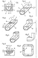
- FIG. 1 shows a cross section through the edge of an insulating glass pane; 2 and 3 in oblique view a first embodiment of the method; 4 and 5 in oblique view a second embodiment of the method;
- FIG. 6 shows a longitudinal section through the still elongated profile according to FIG. 4 in the region of the incisions provided for corner formation;
- Fig. 7 is a view of the frame corner obtained by bending according to Fig. 5 and
- Fig. 8 is a view of a frame and the location of the final joints.
- FIG. 1 shows the edge of an insulating glass pane in cross section.
- Two panes 1 and 2 are spaced apart from one another by a frame 3 which is made from a light metal profile 20.
- the profile 20 shown in FIG. 1 is known per se and is formed by rolling.
- the wall section 4 of the profile bar 20, which forms the inside of the frame 3, has a slot 5.
- the side flanks 6 are stepped and thereby taper the profile width in lower part of the profile bar 20 or on the outside of the frame.
- a permanently elastic sealant and adhesive 7 is on the one hand on the flanks of the profile rod 20, on the other hand on the glass panes 1 and 2 and ensures a functional bond of these parts.
- the outer cavity which is delimited by the pane edges and by the outside of the profile frame, is filled with a likewise permanently elastic sealing compound 8.
- the cavity 9 of these profile bars 20 receives a hygroscopic material 9, not shown here, which interacts with the interior 10 of the pane via the slit 5 or via a possible perforation in this wall section 4.
- This hygroscopic material is offered by the relevant industry in the form of small beads. The diameter of these beads is approximately 1 to 2 mm.
- a profile rod 20 is selected for the length that corresponds to the circumference of the frame to be manufactured.
- the profile bar (FIG. 2) is now cut in the area of the bending points, specifically in that wall section 4 which has the slits 5 or perforations.
- This incision 11 runs transversely to the longitudinal extent of the profile bar.
- the depth t of the incision 11 corresponds at least to the wall thickness s of this edge section e.
- the sections A and B of the profiled bar formed by such incisions 11 are bent against one another (arrow 12), thereby forming a frame corner (FIG. 3).
- a further development of the method consists in the fact that several parallel incisions 11 ', preferably three such incisions 11' are provided in the provided corner areas (FIGS. 4 and 6). Webs 14 remain between the individual incisions 11 '. The width b of the individual incisions 11' corresponds approximately to the width c of the remaining webs 14.
- FIG. 7 Such a frame corner with the position of the deformed incisions is shown in a side view in FIG. 7.
- the total width B of the incisions (FIG. 6) is chosen to be approx. 6 mm.
- the incisions are each about 1 mm wide and the webs remaining between them are about 1.5 mm. This results in a total incision width B of 6 mm.
- the profile strips can be filled with the aforementioned hygroscopic material before this processing or after cutting.
- the end sides of the profile are then clogged, so that this spherical material cannot flow out.
- the special shape of the incisions also prevents this hygroscopic material from escaping.
- the incisions are placed in a section bar cut to length so that in the frame to be manufactured (FIG. 8) the two profile ends 17 and 18 lie in a straight part of the frame to be manufactured.
- these ends can easily be combined with a suitable coupling or with a suitable adapter.
- this joint reaches an area of the frame that is easy to control in terms of production technology in the manufacture of the insulating glass pane.
- the previously so feared weak points in these insulating glass panes are therefore completely eliminated thanks to the invention.
- FIGS. 9 to 12 show profiles, FIGS. 9 to 12, FIG. 9 showing the prepared and FIG. 10 the folded or bent profile piece, and this profile has a simple rectangular cross section. This profile is formed by roles.
- the starting material for this profile was a flat strip, which was folded into this closed box profile by means of appropriate deflection rollers.
- 11 shows a drawn profile with a longitudinal perforation 21, also prepared for the bending process, and
- FIG. 12 shows the bent or bent profile.
- Such profiles usually consist of light metal alloys.
- the invention is not restricted to such light metal profiles, it can also be used successfully with profiles that are drawn or rolled, for example, from steel.
- the side flanks remain essentially flat, which is extremely important for these frame profiles, for reasons that have already been explained in the introduction.
- the outer boundary side is deformed not insignificantly in the corner area, but this does not affect the quality of the frame, on the contrary, this deformation then saves a relatively large amount of space in the outer corner area of the pane, which can then be completely filled with sealing compound, so that the sealing material has accumulated especially in areas of increased risk.
Abstract
Description
- Die Erfindung bezieht sich auf ein Verfahren zur Herstellung eines Distanzhalterahmens für Isolierglasscheiben aus einem Hohlprofilstab, dessen Höhlung für die Aufnahme von hygroskopischen Materialien vorgesehen ist und dessen die Innenseite des zu fertigenden Rahmens bildender Wandabschnitt eine vorzugsweise in Längsrichtung des Hohlprofilstabes verlaufende Schlitzung oder Profilierung aufweise sowie auf einen Distanzhalterahmen, der nach diesem Verfahren hergestellt ist.
- Distanzhalterahmen für Isolierglasscheiben sind in vielfältiger Form bekannt. Sie werden in der Regel aus Leichtmetallprofilen hergestellt. Entsprechend den Seitenlängen des Rahmens werden die Profilleisten abgeschnitten und dann wird derRAhmen aus diesen einzelnen Profilstangen zusammengefügt. Für die Rahmenecken stehen eigene Eckverbinder oder Eckstücke zur Verfügung. Ferner ist es möglich, die Ender der einzelnen Profilstäbe in den Rahmenecken stumpft aneinander stoßen zu lassen oder auch über Gehrungsschnitte zusammen zu fügen. Allen Profilleisten für solche Rahmen ist gemeinsam, daß sie als Hohlprofile ausgebildet sind. Die Höhlung dieser Profile dient der Aufnahme von hygroskopischen Materialien, die in Form von kleinen Kügelchen von einschlägigen Unternehmen auf dem Markt angeboten werden. Über die Schlitzung bzw. Perforierung im Hohlprofil wirkt dieses Material mit dem Innenraum der Isolierglasscheibe in bekannter Weise zusammen. Die erwähnten Ecken des Distanzhalterahmens, seien sie nun durch stumpfes Aneinanderstoßen der Profilstäbe, durch Verbinden derselben in einem Gehrungsschnitt oder durch den Einsatz von Eckwinkeln gebildet, sind bei jeder Isolierglasscheibe sogenannte Schwachstellen, die einer besonders sorgfältigen Ver- und Bearbeitung bedürfen und die trotzdem häufig Anlaß zu Reklamationen bilden, vor allem bei solchen Scheiben, die einer extremen Atmosphäre ausgesetzt sind (beispielsweise Scheiben in Hallenbädern oder in Werkhallen).
- Die Erfindung zielt daher auf ein Verfahren ab, bei dessen Wanwendung es möglich ist, aus einem Profilstab entsprechender Länge durch winkeliges Umbiegen einzelner Stababschnitte einen Rahmen zu fertigen. Die Stoßstellen der beiden Profilstabenden können dabei in einem geraden Verlauf einer Rahmenseite vorgesehen werden. Auf die dadurch erzielbaren Vorteile wird nachstehend noch im einzelnen eingegangen werden. Gekennzeichnet ist das erfindungsgemäße Verfahren nun dadurch, daß der Profilstab an seinem die Schlitzung oder Perforierung aufweisenden Wandabschnitt quer zu seiner Längsrichtung zumindest im Ausmaß der Stärke dieses Wandabschnittes eingeschnitten wird und die durch diesen Einschnitt gebildeten Abschnitte des Profilstabes zur Bildung einer Rahmenecke gegeneinander gebogen werden.
- Um die Erfindung zu veranschaulichen, sei sie ahhand verschiedener Ausführungsformen näher erläutert. Es zeigen: Fig. 1 einen Querschnitt durch den Rand einer Isolierglasscheibe; die Fig. 2 und 3 in Schrägsicht eine erste Ausführungsform des Verfahrens; die Fig. 4 und 5 in Schrägsicht eine zweite Ausführungsform des Verfahrens; Fig. 6 einen Längsschnitt durch das noch gestreckte Profil nach Fig. 4 im Bereich der für die Eckenbildung vorgesehenen Einschnitte; Fig. 7 die Ansicht der durch Biegen erzielten Rahmenecke nach Fig. 5 und Fig. 8 eine Ansicht eines Rahmens und die Lage der Endstoßstellen.
- Den Rand einer Isolierglasscheibe im Querschnitt zeigt Fig. 1. Zwei Scheiben 1 und 2 sind voneinander durch einen Rahmen 3 distanziert, der aus einem Leichtmetallprofil 20 gefertigt ist. Das aus Fig. 1 ersichtliche Profil 20 ist an sich bekannt und es istaurch Rollen gebildet. Der Wandabschnitt 4 des Profilstabes 20, der die Innenseite des Rahmens 3 bildet, weist eine Schlitzung 5 auf. Die Seitenflanken 6 sind stufenartig abgesetzt und verjüngen dadurch die Profilbreite im unteren Teil des Profilstabes 20 bzw. auf der Außenseite des Rahmens. Eine dauerelastische Dicht- und Klebemasse 7 liegt einerseits an den Flanken des Profilstabes 20, andererseits an den Glasscheiben 1 und 2 an und sorgt für einen funktionsgerechten Verbund dieser Teile. Der äußere Hohlraum, der von den Scheibenrändern und von der Außenseite des Profilrahmens begrenzt wird, ist mit einer ebenfalls dauerelastischen Dichtungsmasse 8 ausgefüllt. Allen Profilstäben 20, die für die Fertigung solcher Distanzhalterahmen 3 für Isolierglasscheiben verwendet werden, ist gemeinsam, daß sie als Hohlprofile ausgebildet sind. Die Höhlung 9 dieser Profilstäbe 20 nimmt ein hier nicht dargestelltes hygroskopisches Material 9 auf, das über die Schlitzung 5 bzw. über eine eventuelle Perforierung in diesem Wandabschnitt 4 mit dem Innenraum 10 der Scheibe zusammenwirkt. Dieses hygroskopische Material wird von der einschlägigen Industrie in Form von kleinen Kügelchen angeboten. Der Durchmesser dieser Kügelchen liegt ca. bei 1 bis 2 mm.
- Für die Fertigung eines Rahmens 3, die ausschließlich durch winkeliges Biegen einzelner Profilabschnitte durchgeführt werden soll, wird vorerst ein Profilstab 20 von jener Länge gewählt, die dem Umfang des zu fertigenden Rahmens entspricht. Im Bereich der Biegestellen wird nun der Profilstab (Fig. 2) eingeschnitten, und zwar in jenem Wandabschnitt 4, der die Schlitzung 5 oder Perforierung aufweist. Dieser Einschnitt 11 verläuft quer zur Längserstreckung des Profilstabes. Die Tiefe t des Einschnittes 11 entspricht dabei zumindest der Wandstärke s dieses Randabschnittes e. Anschließend werden nun die durch solche Einschnitte 11 gebildeten Abschnitte A und B des Profilstabes gegeneinander gebogen (Pfeil 12) und dadurch eine Rahmenecke (Fig. 3) gebildet. Die Außenseite des Rahmens verformt sich zwar in diesem Eckbereich nicht unerheblich, wesentlich ist jedoch, daß die Seitenflanken 13 des Profiles sich nicht nach außen wölben, sondern im wesentlichen eben bleiben, wie umfangreiche Versuche bescheinigt haben. Während des Biegevorganges können die Eckzonen bzw. deren Flanken 13 auch fürsorglich in einem Werkstück geführt werden, damit verläßlich ein Aufwölben dieser Flanken im Eckbereich verhindert wird.
- Eine weitere Entwicklung des Verfahrens besteht nun darin, daß in den vorgesehenen Eckbereichen mehrere parallele Einschnitte 11', vorzugsweise drei solche Einschnitte 11' vorgesehen werden (Fig. 4 und Fig. 6). Zwischen den einzelnen Einschnitten 11' verbleiben Stege 14. Die Breite b der einzelnen Einschnitte 11' entspricht etwa der Breite c der verbleibenden Stege 14. Die Einschnittiefe ist hier etwas größer gewählt, als es der Wandstärke s des Profilstabes 20 entsprechen würde.
- Beim nachfolgenden winkeligen Umbiegen (Pfeil 12') stoßen die beiden äußeren Begrenzungskanten 15 und 16 dieser Einschnitte aneinander (Fig. 7) und klemmen zwischen sich formschlüssig die Stege 14 ein, wobei ein im wesentlichen gleichmäßiger, in den Flanken der Ecke ebener Materialverlauf erreicht wird. Eine solche Rahmenecke mit der Lage der verformten Einschnitte zeigt in Seitensicht die Fig. 7. Bei einer Profilbreite von ca. 12 mm wird die gesamte Breite B der Einschnitte (Fig. 6) mit ca. 6 mm gewählt. Die Einschnitte sind jeweils ca. 1 mm breit und die dazwischen verbleibenden Stege ca. 1,5 mm. Dies ergibt in der Summe die Einschnittbreite B von 6 mm. Da diese Einschnitte sehr schmal sind, können die Profilleisten bereits vor dieser Bearbeitung oder aber auch nach dem Einschneiden mit dem erwähnten hygroskopischen Material gefüllt werden. Die Endseiten des Profils werden dann verstopft, so daß dieses kugelförmige Material nicht ausfließen kann. Die besondere Form der Einschnitte verhindert ebenfalls das Austreten dieses hygroskopischen Materials. Die Einschnitte werden bei einer abgelängten Profilleiste so gelegt, daß bei dem zu fertigenden Rahmen (Fig. 8) die beiden Profilenden 17 und 18 in einem gerade verlaufenden Teil des zu fertigenden Rahmens liegen. Hier können diese Enden einfach vereinigt werden mit einer geeigneten Kupplung oder mit einem geeigneten Zwischenstück. Dadurch gelangt diese Stoßstelle in einen Bereich des Rahmens, der bei der Fertigung der Isolierglasscheibe fertigungstechnisch leicht zu beherrschen ist. Die früher so gefürchteten Schwachstellen bei diesen Isolierglasscheiben sind daher dank der Erfindung vollständig eliminiert.
- Wenn die Erfindung hier anhand ein und desselben Profilquerschnittes näher erläutert worden ist, so muß hier noch festgehalten werden, daß sie nicht auf die Anwendung bei solchen Profilen beschränkt ist. Die Erfindung ist auch verwendbar bei anderen Profilformen, wie sie für die Herstellung bei solchen Distanzhalterahmen gebräuchlich sind und die ebenfalls Hohlkammern für die Aufnahme von hygroskopischem Material besitzen. Solche Profile sind in den Fig. 9 bis 12 gezeigt, wobei die Fig. 9 das vorbereitete und Fig. 10 das abgekantete oder umgebogene Profilstück zeigen, und dieses Profil einen einfachen rechteckigen Querschnitt aufweist. Dieses Profil ist durch Rollen gebildet. Das Ausgangsmaterial für dieses Profil war ein flacher Streifen, der durch entsprechende Umlenkrollen zu diesem geschlossenen Kastenprofil gefaltet wurde. Die Fig. 11 zeigt ein gezogenes Profil mit einer Längsperforierung 21, ebenfalls für den Biegevorgang vorbaeitet und Fig. 12 das abgekantete bzw. umgebogene Profil. Solche Profile bestehen in der Regel aus Leichtmetalllegierungen. Es ist jedoch die Erfindung nicht auf solche Leichtmetallprofile beschränkt, sie kann mit Erfolg auch bei solchen Profilen angewendet werden, die beispielsweise aus Stahl gezogen oder gerollt sind. In allen den aufgezeigten Fällen ergibt sich eine exakte einwandfreie innere Stoßkante, die seitlichen Flanken verbleiben im wesentlichen eben, was für diese Rahmenprofile ja außerordentlich wichtig ist und zwar aus Gründen, die schon einleitend dargelegt wurden. Die jeweils äußere Begrenzungsseite wird zwar im Eckbereich nicht unerheblich verformt, dies beeinflußt jedoch die Qualität des Rahmens nicht, im Gegenteil, durch dieseVerformung wird dann im äußeren Eckbereich der Scheibe relativ viel Raum ausgespart, der dann zur Gänze mit Dichtungsmasse ausgefüllt werden kann, so daß gerade in den Bereichen erhöhter Gefährdung das Dichtungsmaterial angehäuft ist.
Claims (8)
Applications Claiming Priority (2)
| Application Number | Priority Date | Filing Date | Title |
|---|---|---|---|
| AT0086378A AT366771B (de) | 1978-02-08 | 1978-02-08 | Verfahren zur herstellung eines distanzhalterahmens fuer isolierglasscheiben |
| AT863/78 | 1978-02-08 |
Publications (2)
| Publication Number | Publication Date |
|---|---|
| EP0003715A1 true EP0003715A1 (de) | 1979-08-22 |
| EP0003715B1 EP0003715B1 (de) | 1981-11-04 |
Family
ID=3501543
Family Applications (1)
| Application Number | Title | Priority Date | Filing Date |
|---|---|---|---|
| EP19790810004 Expired EP0003715B1 (de) | 1978-02-08 | 1979-01-22 | Distanzhalterahmen für Isolierglasscheiben |
Country Status (3)
| Country | Link |
|---|---|
| EP (1) | EP0003715B1 (de) |
| AT (1) | AT366771B (de) |
| DE (1) | DE2961178D1 (de) |
Cited By (9)
| Publication number | Priority date | Publication date | Assignee | Title |
|---|---|---|---|---|
| FR2405907A1 (fr) * | 1977-10-15 | 1979-05-11 | Erbsloeh Julius & August | Entretoise pour vitrage isolant a vitres multiples, procede et dispositif pour sa fabrication |
| EP0132516A2 (de) * | 1983-07-16 | 1985-02-13 | Helmut Lingemann GmbH & Co. | Gebogene Ecke eines Abstandhalterrahmens einer Isolierverglasung sowie Verfahren zu ihrer Herstellung |
| EP0146883A2 (de) * | 1983-12-23 | 1985-07-03 | Karl Lenhardt | Verfahren zum Formen der Ecken von Abstandhalterrahmen für randverklebte Isolierglasscheiben |
| WO1986001248A1 (en) * | 1984-08-10 | 1986-02-27 | Lars Eriksson | Profile spacing element for forming a window comprising more than one glass in a window frame |
| GB2237051A (en) * | 1989-10-21 | 1991-04-24 | Gary Daynes | Square cornered spacer tube & method of making it |
| DE4231683A1 (de) * | 1992-03-31 | 1993-10-07 | Lenhardt Maschinenbau | Verfahren und Vorrichtung zum Herstellen von Abstandshalterrahmen zur Verwendung zwischen den Glastafeln von Isolierglasscheiben |
| US5361476A (en) * | 1992-08-13 | 1994-11-08 | Glass Equipment Development, Inc. | Method of making a spacer frame assembly |
| WO1998050663A1 (de) * | 1997-05-01 | 1998-11-12 | Saint-Gobain Vitrage Suisse Ag | Verfahren zur herstellung von abgewinkelten hohlprofil-leisten |
| EP1529920A2 (de) | 2003-11-07 | 2005-05-11 | Technoform Caprano + Brunnhofer GmbH & Co. KG | Abstandshalterprofil für Isolierscheibeneinheit und Isolierscheibeneinheit |
Citations (3)
| Publication number | Priority date | Publication date | Assignee | Title |
|---|---|---|---|---|
| US3380145A (en) * | 1964-01-08 | 1968-04-30 | Pittsburgh Plate Glass Co | Method of fabricating multiple glazing unit |
| US3540118A (en) * | 1968-02-20 | 1970-11-17 | Ppg Industries Inc | Method of framing a multiple glazed unit |
| CA1006052A (en) * | 1975-11-06 | 1977-03-01 | Gaetan Y. Lacombe | Spacer for glass sealed unit and interlock member therefor |
-
1978
- 1978-02-08 AT AT0086378A patent/AT366771B/de not_active IP Right Cessation
-
1979
- 1979-01-22 DE DE7979810004T patent/DE2961178D1/de not_active Expired
- 1979-01-22 EP EP19790810004 patent/EP0003715B1/de not_active Expired
Patent Citations (3)
| Publication number | Priority date | Publication date | Assignee | Title |
|---|---|---|---|---|
| US3380145A (en) * | 1964-01-08 | 1968-04-30 | Pittsburgh Plate Glass Co | Method of fabricating multiple glazing unit |
| US3540118A (en) * | 1968-02-20 | 1970-11-17 | Ppg Industries Inc | Method of framing a multiple glazed unit |
| CA1006052A (en) * | 1975-11-06 | 1977-03-01 | Gaetan Y. Lacombe | Spacer for glass sealed unit and interlock member therefor |
Cited By (14)
| Publication number | Priority date | Publication date | Assignee | Title |
|---|---|---|---|---|
| FR2405907A1 (fr) * | 1977-10-15 | 1979-05-11 | Erbsloeh Julius & August | Entretoise pour vitrage isolant a vitres multiples, procede et dispositif pour sa fabrication |
| EP0132516A3 (en) * | 1983-07-16 | 1985-09-25 | Helmut Lingemann Gmbh & Co. | Curved corner of a spacing frame of an insulating glazing and method of manufacturing it |
| EP0132516A2 (de) * | 1983-07-16 | 1985-02-13 | Helmut Lingemann GmbH & Co. | Gebogene Ecke eines Abstandhalterrahmens einer Isolierverglasung sowie Verfahren zu ihrer Herstellung |
| US4597232A (en) * | 1983-07-16 | 1986-07-01 | Helmut Lingemann Gmbh & Co. | Curved corner of a spacer frame of an insulating glazing, and a process for the production thereof |
| EP0146883A3 (en) * | 1983-12-23 | 1985-08-07 | Karl Lenhardt | Corner forming method for spacer frames of edge-sealed insulating glazing units |
| EP0146883A2 (de) * | 1983-12-23 | 1985-07-03 | Karl Lenhardt | Verfahren zum Formen der Ecken von Abstandhalterrahmen für randverklebte Isolierglasscheiben |
| WO1986001248A1 (en) * | 1984-08-10 | 1986-02-27 | Lars Eriksson | Profile spacing element for forming a window comprising more than one glass in a window frame |
| GB2237051A (en) * | 1989-10-21 | 1991-04-24 | Gary Daynes | Square cornered spacer tube & method of making it |
| DE4231683A1 (de) * | 1992-03-31 | 1993-10-07 | Lenhardt Maschinenbau | Verfahren und Vorrichtung zum Herstellen von Abstandshalterrahmen zur Verwendung zwischen den Glastafeln von Isolierglasscheiben |
| US5361476A (en) * | 1992-08-13 | 1994-11-08 | Glass Equipment Development, Inc. | Method of making a spacer frame assembly |
| WO1998050663A1 (de) * | 1997-05-01 | 1998-11-12 | Saint-Gobain Vitrage Suisse Ag | Verfahren zur herstellung von abgewinkelten hohlprofil-leisten |
| EP1529920A2 (de) | 2003-11-07 | 2005-05-11 | Technoform Caprano + Brunnhofer GmbH & Co. KG | Abstandshalterprofil für Isolierscheibeneinheit und Isolierscheibeneinheit |
| US6989188B2 (en) | 2003-11-07 | 2006-01-24 | Technoform Caprano Und Brunnhofer Gmbh & Co. Kd | Spacer profiles for double glazings |
| DE202004021841U1 (de) | 2003-11-07 | 2011-08-05 | Technoform Glass Insulation Holding Gmbh | Abstandshalterprofil für Isolierscheibeneinheit und Isolierscheibeneinheit |
Also Published As
| Publication number | Publication date |
|---|---|
| ATA86378A (de) | 1981-09-15 |
| EP0003715B1 (de) | 1981-11-04 |
| AT366771B (de) | 1982-05-10 |
| DE2961178D1 (en) | 1982-01-14 |
Similar Documents
| Publication | Publication Date | Title |
|---|---|---|
| DE3337058C1 (de) | Abstandhalter fuer Fenster,Tueren o.dgl. | |
| EP2476853A1 (de) | Verbundprofil für Fenster, Türen und Fassaden sowie Verfahren zu dessen Herstellung | |
| EP0132516B1 (de) | Gebogene Ecke eines Abstandhalterrahmens einer Isolierverglasung sowie Verfahren zu ihrer Herstellung | |
| EP0003715A1 (de) | Distanzhalterahmen für Isolierglasscheiben | |
| CH642713A5 (de) | Abstandshalter fuer mehrscheiben-isolierglas sowie verfahren und vorrichtung zu dessen herstellung. | |
| DE2829444A1 (de) | Abstandshalter fuer mehrscheiben-isolierglas sowie verfahren und vorrichtung zu seiner herstellung | |
| EP0477513B1 (de) | Verbindungsvorrichtung für eine Sprossenkreuzkonstruktion | |
| AT406076B (de) | Profilleiste für abstandhalter für isolierglasscheiben und isolierglasscheibe | |
| DE2912020C2 (de) | Verfahren zur Herstellung eines Rahmens | |
| DE2457475C2 (de) | Isolierglas und Verfahren zu dessen Herstellung | |
| DE2606387C3 (de) | Rohrförmiger Profilschenkel | |
| DE3119468C2 (de) | Eckverbindung für Hohlprofile aus Leichtmetall | |
| DE102004027527A1 (de) | Verfahren zum Herstellen einer Isolierglasscheibe | |
| DE2160847A1 (de) | Isolierglaseinheit | |
| DE3129567A1 (de) | Verfahren zur herstellung von hart-kunststoffprofilen mit einem durch einschieben einzubringenden metallrohr und durch dieses verfahren hergestellten kunststoffprofil | |
| DD202333A5 (de) | Gehrungseckverbindung fuer profilstaeben zusammengesetzte rahmen, insb. fenster- und tuerrahmen und dgl. | |
| DE3838482C2 (de) | ||
| DE2216038C3 (de) | Rohrförmiges Abstandhalter-Profil für Isolierverglasungen | |
| DE2532896C3 (de) | Eckverbindung zweier Hohlprofile eines Abstandhalterrahmens einer Isolierglasscheibe | |
| EP0266609A1 (de) | Schrank, insbesondere Badezimmerschrank | |
| DE3439782C2 (de) | Türflügel | |
| DE2623750C2 (de) | Verfahren zum Herstellen von Rahmen | |
| DE3412738C2 (de) | ||
| AT351731B (de) | Profilstab fuer distanzhalterahmen bei isolier- glasscheiben | |
| DE2649021A1 (de) | Eckverbindung und verfahren zu deren herstellung |
Legal Events
| Date | Code | Title | Description |
|---|---|---|---|
| PUAI | Public reference made under article 153(3) epc to a published international application that has entered the european phase |
Free format text: ORIGINAL CODE: 0009012 |
|
| AK | Designated contracting states |
Designated state(s): BE CH DE FR GB IT LU NL SE |
|
| 17P | Request for examination filed | ||
| ITF | It: translation for a ep patent filed |
Owner name: INTERPATENT ST.TECN. BREV. |
|
| GRAA | (expected) grant |
Free format text: ORIGINAL CODE: 0009210 |
|
| AK | Designated contracting states |
Designated state(s): BE CH DE FR GB IT LU NL SE |
|
| REF | Corresponds to: |
Ref document number: 2961178 Country of ref document: DE Date of ref document: 19820114 |
|
| ITTA | It: last paid annual fee | ||
| PGFP | Annual fee paid to national office [announced via postgrant information from national office to epo] |
Ref country code: CH Payment date: 19901217 Year of fee payment: 13 |
|
| PGFP | Annual fee paid to national office [announced via postgrant information from national office to epo] |
Ref country code: SE Payment date: 19901219 Year of fee payment: 13 |
|
| PGFP | Annual fee paid to national office [announced via postgrant information from national office to epo] |
Ref country code: BE Payment date: 19910103 Year of fee payment: 13 |
|
| PGFP | Annual fee paid to national office [announced via postgrant information from national office to epo] |
Ref country code: LU Payment date: 19910109 Year of fee payment: 13 |
|
| PGFP | Annual fee paid to national office [announced via postgrant information from national office to epo] |
Ref country code: GB Payment date: 19910118 Year of fee payment: 13 |
|
| PGFP | Annual fee paid to national office [announced via postgrant information from national office to epo] |
Ref country code: DE Payment date: 19910121 Year of fee payment: 13 |
|
| PGFP | Annual fee paid to national office [announced via postgrant information from national office to epo] |
Ref country code: FR Payment date: 19910123 Year of fee payment: 13 |
|
| PGFP | Annual fee paid to national office [announced via postgrant information from national office to epo] |
Ref country code: NL Payment date: 19910131 Year of fee payment: 13 |
|
| EPTA | Lu: last paid annual fee | ||
| PG25 | Lapsed in a contracting state [announced via postgrant information from national office to epo] |
Ref country code: LU Free format text: LAPSE BECAUSE OF NON-PAYMENT OF DUE FEES Effective date: 19920122 Ref country code: GB Effective date: 19920122 |
|
| PG25 | Lapsed in a contracting state [announced via postgrant information from national office to epo] |
Ref country code: SE Effective date: 19920123 |
|
| PG25 | Lapsed in a contracting state [announced via postgrant information from national office to epo] |
Ref country code: CH Effective date: 19920131 Ref country code: BE Effective date: 19920131 |
|
| BERE | Be: lapsed |
Owner name: SPS GLASBAU SERAPHIN RUMPEL & SOHNE G.M.B.H. Effective date: 19920131 |
|
| PG25 | Lapsed in a contracting state [announced via postgrant information from national office to epo] |
Ref country code: NL Effective date: 19920801 |
|
| NLV4 | Nl: lapsed or anulled due to non-payment of the annual fee | ||
| REG | Reference to a national code |
Ref country code: GB Ref legal event code: PCNP |
|
| PG25 | Lapsed in a contracting state [announced via postgrant information from national office to epo] |
Ref country code: FR Effective date: 19920930 |
|
| REG | Reference to a national code |
Ref country code: CH Ref legal event code: PL |
|
| PG25 | Lapsed in a contracting state [announced via postgrant information from national office to epo] |
Ref country code: DE Effective date: 19921001 |
|
| REG | Reference to a national code |
Ref country code: FR Ref legal event code: ST |
|
| EUG | Se: european patent has lapsed |
Ref document number: 79810004.6 Effective date: 19920806 |
|
| PLBE | No opposition filed within time limit |
Free format text: ORIGINAL CODE: 0009261 |
|
| STAA | Information on the status of an ep patent application or granted ep patent |
Free format text: STATUS: NO OPPOSITION FILED WITHIN TIME LIMIT |