EP0001152A1 - Système de transfert de palettes - Google Patents
Système de transfert de palettes Download PDFInfo
- Publication number
- EP0001152A1 EP0001152A1 EP78200181A EP78200181A EP0001152A1 EP 0001152 A1 EP0001152 A1 EP 0001152A1 EP 78200181 A EP78200181 A EP 78200181A EP 78200181 A EP78200181 A EP 78200181A EP 0001152 A1 EP0001152 A1 EP 0001152A1
- Authority
- EP
- European Patent Office
- Prior art keywords
- pallet
- thrust
- drive
- positions
- conveyor
- Prior art date
- Legal status (The legal status is an assumption and is not a legal conclusion. Google has not performed a legal analysis and makes no representation as to the accuracy of the status listed.)
- Granted
Links
Images


Classifications
-
- B—PERFORMING OPERATIONS; TRANSPORTING
- B23—MACHINE TOOLS; METAL-WORKING NOT OTHERWISE PROVIDED FOR
- B23Q—DETAILS, COMPONENTS, OR ACCESSORIES FOR MACHINE TOOLS, e.g. ARRANGEMENTS FOR COPYING OR CONTROLLING; MACHINE TOOLS IN GENERAL CHARACTERISED BY THE CONSTRUCTION OF PARTICULAR DETAILS OR COMPONENTS; COMBINATIONS OR ASSOCIATIONS OF METAL-WORKING MACHINES, NOT DIRECTED TO A PARTICULAR RESULT
- B23Q7/00—Arrangements for handling work specially combined with or arranged in, or specially adapted for use in connection with, machine tools, e.g. for conveying, loading, positioning, discharging, sorting
- B23Q7/14—Arrangements for handling work specially combined with or arranged in, or specially adapted for use in connection with, machine tools, e.g. for conveying, loading, positioning, discharging, sorting co-ordinated in production lines
- B23Q7/1426—Arrangements for handling work specially combined with or arranged in, or specially adapted for use in connection with, machine tools, e.g. for conveying, loading, positioning, discharging, sorting co-ordinated in production lines with work holders not rigidly fixed to the transport devices
- B23Q7/1431—Work holder changers
Definitions
- the invention relates to a pallet conveyor with pallet conveyance on a circular path, any number of pallet receptacles have pallet guides arranged at right angles to the conveying direction and can be moved into several transfer positions and on which the pallets are mechanically displaced in the direction of the pallet guides.
- Such pallet conveyors with a turntable that can be rotated by 180 in two angular positions and which carries only two pallet receptacles are also known as pallet changers.
- a pallet pusher drive is assigned to each pallet holder, and the pallets are moved alternately onto the work machine and back by each pallet pusher drive. Both identical pallet push drives have the same push paths with two stop positions that limit the push path.
- each work machine is assigned a pallet changer as a connection unit to the conveyor line.
- Pallet changers have also been proposed, the rotating platform of which also carries four pallet holders and can be rotated in four 90 ° positions.
- a pallet feed drive is assigned to each pallet holder.
- These pallet push drives are identical and have the same push paths with two stop positions that limit the push path.
- the object of the invention is to create a pallet conveyor that ensures improved conditions for cost-effective creation and for economical and adaptable use of manufacturing systems.
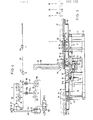
- the pallet conveyor shown in Figures 1, 2, 3 has the base 10, which consists essentially of two polygonal rings 11, 12 connected by vertical supports 13. On the underside of the upper ring 11, two cross members 7 are screwed, between which the base hub 9 is welded.
- the top of the upper ring 11 is formed as an annular support track with hardened plates 14 on which a rotating stage 15 is supported, which is centered by means of a bearing pin 16 flanged vertically on the base hub 9 and the roller bearing 17.
- a hydraulic control unit 8 is arranged within the base 10.
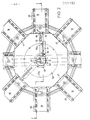
- the rotating platform 15 consists of the octagonal central part 18, on the eight vertical outer walls of which eight pallet receptacles 19 are screwed.
- Each pallet holder has on its upper side a pallet guide formed by rollers 20, on which the pallets 21 shown in phantom in FIG. 1 are radially displaceable.
- a pallet pusher drive 26 with a finite chain 30 as a pusher element is arranged in the center of the pallet conveyor.
- the chain links in a known manner according to FIG. 3 each have a stop plate 29 on their lower or left side in order to prevent an upward buckling under load and also to enable a self-supporting extension.
- the chain 30 is moved in both directions by a hydraulic motor 27 by means of the drive wheel 28, and a coupling piece 34 which cooperates with the pallet pawls 35 is fastened to its outer end.
- the inner end of the chain 30 winds up and down during the chain movement in a guide frame 36 which is located on the bearing housing 31 for the hydraulic motor 27 and the drive wheel 28.
- the bearing housing 31 is screwed coaxially to the bearing pin 16 on the upper side of an arm 44, which in turn is flanged on the upper end face of an adjusting sleeve 32 rotatably mounted in the bore of the bearing pin 16.
- an angular orientation 33 By means of an angular orientation 33, the adjusting sleeve 32 with the arm 44 and the bearing housing 31 can be rotated independently of the rotating platform 15.
- the angular orientation 33 consists of a stepper motor 38 with reduction gear 43 fastened to the cross strut 7, the pinion 39 of which cooperates with a spur gear 40 which is wedged beneath the bearing pin 16 on the projecting part of the adjusting sleeve 32.
- the stepper motor 38 can be controlled such that the adjusting sleeve 32, the arm 44, the bearing housing 31 and thus the direction of thrust of the chain 30 can be oriented into any required 45 ° angular position.
- dash-dotted lines indicate a thrust direction that is not in the drawing plane of FIGS. 1 and 3.
- the hydraulic motor 27 for shifting the pallet is acted upon by the feed bushing 41 mounted at the lower end of the adjusting sleeve 32, including two of its three connections 50 and the oil bores 42, 43 located in the adjusting sleeve serve.
- the third connection and a third oil hole, not shown, serve for one-sided loading of the index piston drive 45, the resetting of which is done by means of a better overview due to the spring not shown.
- the coupling piece 34 with or without a pallet 21 can be moved into an inner push position I and three outer push positions II, III, IV.
- the inner thrust position I can be retracted in any angular position of the pallet thrust drive 26, while the outer thrust positions II, III, IV only have to be moved in as an alternative, as will become apparent later from the description of the manufacturing systems.
- two upward-acting switching pieces 48, 49 are arranged in one switching track on one side of the chain 30.
- the retraction of the coupling piece 34 from the thrust position 1 in the thrust positions II or 111 is controlled by flow control valves 58, 59 connected in series, which are located at a distance "r” or respectively.
- "R" based on the axis of rotation of the rotating stage 15, are arranged in the base 10 in a number and angular position, as required by the transfer positions of the respective production system. They are actuated by means of the switching pieces 54, 55 arranged on both chain sides and acting downward in two further switching tracks, via plungers 56, 56a and push rods 57, 57a.
- the switching element 54 can act in the one switching track against spring pressure on the plunger 56 guided vertically in the arm 44 at a distance "r", and the switching element 55 can act in the other switching track against spring pressure on the plunger guided vertically in the arm 44 with a distance "R” 56a act.
- a vertically guided push rod 57 with a smaller pitch circle diameter of 2 x "r” and a vertically guided push rod 57a with a larger pitch circle diameter 2 x "R” are in the middle part 18 of the rotating platform 15 of each pallet holder. assigned.
- the pushrods are held by upward spring forces and stop rings in the unloaded state of the circuit with a small distance to the lower ends of the plungers 56, 56a, so that the rotating platform 15 and the pallet slide drive 26 can rotate independently of one another with the arm 44.
- a locking cylinder 75 is installed in each pallet receptacle 19, the vertical piston rod 76 of which is held downwards under spring pressure while the pallets 21 are being retracted into the inner thrust position I (FIG. 5).
- the respective locking cylinder 75 is acted upon by the hydraulic control unit 8 via the lines 82 through the feed bushing 77, which is fixed on the bearing journal 16 on the bearing flange 6 of the rotating platform 15.
- the piston rod 76 penetrates into the pallet bore 78 and presses the angle lever 80, which can be pivoted in the pallet 21 about the bolt 79, with the pallet pawl 35 attached to it upwards into the release from the coupling piece 34 (FIG. 6).
- FIG. 7 shows the simplest version of a pallet conveyor according to the invention for approximately eight pallet receptacles, which can be used with a direct pallet transfer to the machines with a short pallet shift.
- a working cylinder 60 which can be acted upon directly by the feed bushing 41 is screwed onto the support arm 44 instead of the chain thrust gear.
- Its piston rod 61 can be moved in two stop positions with the coupling piece 62 located at its outer end.
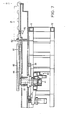
- FIG. 8 shows a pallet conveyor with a one-piece rotating platform 70 and two pallet holders.
- the pallet thrust drive 83 which works with a chain and which is centered and screwed on by means of a plate 84 on the upper end face of the adjusting sleeve 85, enables a centric force application during the pallet displacement, despite the fact that the pallet receptacles are arranged close together on the rotating platform 70 in a space-saving manner.
- This structure is made possible in particular by the fact that the chain 30 is wound in the guide frame 36 arranged coaxially to the bearing journal 86.
- the well-known, similarly space-saving pallet changers have a working cylinder on each long side of the rotating platform for pallet displacement with lateral force application, which causes disadvantageous corner moments and requires additional guide elements).
- the 180 ° expansion of the rotating platform 70 is carried out by means of the toothed piston drive 71, which cooperates with a spur toothing 69 of the bearing hub 72 flanged to the rotating platform.
- the pallet thrust drive 83 has two thrust positions I and II, and a small toothed piston drive 73 is used for the angle adjustment in its two 180 ° positions, which engages in the stirp / toothing 74 machined in eir2 at the lower end of the adjusting sleeve 85.
- the energy supply to the locking cylinders 75 and to the hydraulic motor of the pallet school drive 83 takes place with flexible lines (not shown) which are guided through the large bore 87 of the adjusting sleeve 85.
- FIG. 9 shows a pallet changer similar to that explained in FIG. 8, but, however, carries out a pallet change only in one push direction.
- the pallet push drive 83 is fixedly mounted on the bearing journal 86, and the angular orientation is omitted.
- the advantages of this design which is based on the subject of the invention, are the adaptable drawer lengths of only one pallet thrust drive and the central application of force during pallet displacement with a compact design.
Landscapes
- Engineering & Computer Science (AREA)
- Mechanical Engineering (AREA)
- Automatic Assembly (AREA)
- Feeding Of Workpieces (AREA)
Applications Claiming Priority (2)
| Application Number | Priority Date | Filing Date | Title |
|---|---|---|---|
| CH1121277A CH621991A5 (fr) | 1977-09-14 | 1977-09-14 | |
| CH11212/77 | 1977-09-14 |
Publications (2)
| Publication Number | Publication Date |
|---|---|
| EP0001152A1 true EP0001152A1 (fr) | 1979-03-21 |
| EP0001152B1 EP0001152B1 (fr) | 1980-07-23 |
Family
ID=4371169
Family Applications (1)
| Application Number | Title | Priority Date | Filing Date |
|---|---|---|---|
| EP78200181A Expired EP0001152B1 (fr) | 1977-09-14 | 1978-09-11 | Système de transfert de palettes |
Country Status (5)
| Country | Link |
|---|---|
| US (1) | US4326624A (fr) |
| EP (1) | EP0001152B1 (fr) |
| CH (1) | CH621991A5 (fr) |
| DE (1) | DE2860082D1 (fr) |
| IT (1) | IT1098578B (fr) |
Cited By (2)
| Publication number | Priority date | Publication date | Assignee | Title |
|---|---|---|---|---|
| US4664579A (en) * | 1983-08-24 | 1987-05-12 | Schedwin Sven Erik | Arrangement for transferring heavy workpieces |
| CN102481671A (zh) * | 2009-08-25 | 2012-05-30 | 斗山英维高株式会社 | 机床的托板输送装置 |
Families Citing this family (32)
| Publication number | Priority date | Publication date | Assignee | Title |
|---|---|---|---|---|
| US4388989A (en) * | 1981-07-23 | 1983-06-21 | Hoppmann Corporation | Continuous rotary method of transporting articles |
| US4597334A (en) * | 1981-12-07 | 1986-07-01 | Si Handling Systems, Inc. | Turntable for a system of driverless vehicles |
| US4480738A (en) * | 1982-01-18 | 1984-11-06 | Kearney & Trecker Corporation | Workpiece storage and shuttle apparatus |
| US4565480A (en) * | 1982-09-07 | 1986-01-21 | Burgmaster - Houdaille, Inc. | Carousel pallet shuttle |
| KR890003872Y1 (ko) * | 1983-11-11 | 1989-06-08 | 미쓰비시전기 주식회사 | 곡선 에스컬레이터의 메인프레임(main frame) |
| JPS60172429A (ja) * | 1984-02-17 | 1985-09-05 | Aioi Seiki Kk | 加工機械の工具等の片折れチエン式流体圧シリンダ駆動形押引操作装置 |
| US4662282A (en) * | 1985-03-13 | 1987-05-05 | Hitachi Kiden Kogyo Kabushiki Kaisha | Switching device for pneumatic conveyance linear motor actuated |
| DE3542373C2 (de) * | 1985-11-30 | 1994-07-21 | Expert Maschbau | Vorrichtung mit einem Hub-Drehtisch |
| JPH0657376B2 (ja) * | 1985-12-28 | 1994-08-03 | 津田駒工業株式会社 | パレツト交換装置 |
| US4724948A (en) * | 1986-07-11 | 1988-02-16 | Rca Corporation | Automatic clamping and unclamping system |
| IT1215192B (it) * | 1986-10-06 | 1990-01-31 | O C N S P A | Centro di lavorazione con magazzino per gli utensili |
| JPH0449599Y2 (fr) * | 1986-10-16 | 1992-11-20 | ||
| US4938335A (en) * | 1988-05-23 | 1990-07-03 | Francesco Canziani | Method and devices for controlling the unloading of the items in an automatic sorting plant |
| JPH0776052B2 (ja) * | 1989-07-21 | 1995-08-16 | ブラザー工業株式会社 | コンベアシステム |
| JPH0699032B2 (ja) * | 1989-07-26 | 1994-12-07 | ブラザー工業株式会社 | コンベアシステムの搬送体振り分け装置 |
| JPH0423727A (ja) * | 1990-05-18 | 1992-01-28 | Brother Ind Ltd | 搬送装置 |
| US5284252A (en) * | 1991-11-13 | 1994-02-08 | United Parcel Service Of America, Inc. | Automatic rotary sorter |
| US5437534A (en) * | 1992-01-21 | 1995-08-01 | R. R. Donnelley & Sons Company | Lift index table |
| US5494399A (en) * | 1993-02-19 | 1996-02-27 | Rapsco, Inc. | Can end distributor apparatus |
| US5653576A (en) * | 1993-02-19 | 1997-08-05 | Rapsco, Incorporated | Can lid distributor apparatus |
| DE69511586T2 (de) * | 1994-09-06 | 1999-12-02 | Mannesmann Ag | Sortiersystem mit Querband |
| JP3537193B2 (ja) * | 1994-09-19 | 2004-06-14 | 株式会社タチエス | 台車の引込装置 |
| US5668460A (en) * | 1994-10-31 | 1997-09-16 | Lashstar, Inc. | Battery recharger turntable |
| US5713452A (en) * | 1996-04-25 | 1998-02-03 | Steris Corporation | Automated transport system |
| US5988356A (en) * | 1997-09-08 | 1999-11-23 | United Parcel Service Of America, Inc. | Automated diverter capable of sorting bulky articles |
| US6227377B1 (en) | 1997-09-09 | 2001-05-08 | United Parcel Service Of America, Inc. | Automated array sorter for conveyors |
| JP3361769B2 (ja) * | 1999-02-22 | 2003-01-07 | 安田工業株式会社 | 工作機械用のパレット交換装置 |
| US6213279B1 (en) * | 1999-07-15 | 2001-04-10 | Pilot Industries, Inc. | Machine for selectively positioning a work member at a work station |
| IT1317478B1 (it) * | 2000-04-26 | 2003-07-09 | Mini Ricerca Scient Tecnolog | Procedimento per la manipolazione e il trasferimento di forme per ilmontaggio di calzature. |
| CH714282B1 (de) * | 2000-07-06 | 2019-04-30 | Murata Machinery Ltd | Lagersystem mit Förderelementen. |
| JP4680079B2 (ja) * | 2005-09-02 | 2011-05-11 | 株式会社リコー | ワーク搬送装置 |
| JP5527619B2 (ja) * | 2011-11-24 | 2014-06-18 | 株式会社ダイフク | 天井設置型の物品搬送設備 |
Family Cites Families (8)
| Publication number | Priority date | Publication date | Assignee | Title |
|---|---|---|---|---|
| US849970A (en) * | 1904-08-27 | 1907-04-09 | Paul Boyton | Amusement device. |
| US3055517A (en) * | 1961-10-20 | 1962-09-25 | Joseph T Kirkland | Parking garage |
| US3588243A (en) * | 1968-06-14 | 1971-06-28 | Japan Broadcasting Corp | Card handling apparatus |
| DE2162133C3 (de) * | 1971-12-15 | 1978-03-23 | Demag Ag, 4100 Duisburg | Steuereinrichtung für eine Stückgut-Verteilanlage |
| US4014428A (en) * | 1973-05-04 | 1977-03-29 | Ossbahr C | Modular article conveyor |
| BE829530A (fr) * | 1975-05-27 | 1975-09-15 | Installation d'entreposage pour conteneurs et analogues | |
| US4070972A (en) * | 1976-08-03 | 1978-01-31 | Jervis B. Webb Company | Carrier propelling mechanism for power and free conveyors |
| CH602454A5 (fr) * | 1977-01-17 | 1978-07-31 | Oerlikon Buehrle Ag |
-
1977
- 1977-09-14 CH CH1121277A patent/CH621991A5/de not_active IP Right Cessation
-
1978
- 1978-09-08 US US05/940,775 patent/US4326624A/en not_active Expired - Lifetime
- 1978-09-11 EP EP78200181A patent/EP0001152B1/fr not_active Expired
- 1978-09-11 DE DE7878200181T patent/DE2860082D1/de not_active Expired
- 1978-09-13 IT IT27568/78A patent/IT1098578B/it active
Non-Patent Citations (2)
| Title |
|---|
| MACHINES PRODUCTION, 25 Juni 1975, Seiten 29-31, Herausgegeben durch SOFETEC, 22, rue de la Saussière, 92100 BOULOGNE * |
| WERKSTATTSTECHNIK, Band 62, Juli 1972, Seiten 393-398, Herausgegeben durch SPRINGER-VERLAG D-1000 BERLIN 33 * |
Cited By (5)
| Publication number | Priority date | Publication date | Assignee | Title |
|---|---|---|---|---|
| US4664579A (en) * | 1983-08-24 | 1987-05-12 | Schedwin Sven Erik | Arrangement for transferring heavy workpieces |
| CN102481671A (zh) * | 2009-08-25 | 2012-05-30 | 斗山英维高株式会社 | 机床的托板输送装置 |
| EP2471630A2 (fr) * | 2009-08-25 | 2012-07-04 | Doosan Infracore Co., Ltd. | Mécanisme de chargement de palettes pour une machine-outil |
| EP2471630A4 (fr) * | 2009-08-25 | 2013-01-23 | Doosan Infracore Co Ltd | Mécanisme de chargement de palettes pour une machine-outil |
| CN102481671B (zh) * | 2009-08-25 | 2014-08-06 | 斗山英维高株式会社 | 机床的托板输送装置 |
Also Published As
| Publication number | Publication date |
|---|---|
| US4326624A (en) | 1982-04-27 |
| DE2860082D1 (en) | 1980-11-13 |
| IT1098578B (it) | 1985-09-07 |
| EP0001152B1 (fr) | 1980-07-23 |
| CH621991A5 (fr) | 1981-03-13 |
| IT7827568A0 (it) | 1978-09-13 |
Similar Documents
| Publication | Publication Date | Title |
|---|---|---|
| EP0001152B1 (fr) | Système de transfert de palettes | |
| DE3909292C2 (de) | Längs- und Quer-Tischführungs- und -drehmechanismus | |
| DE3625212C2 (de) | Werkstückübergabevorrichtung | |
| EP3579987B1 (fr) | Magasin d'outils de cintrage et procédé de chargement d'une presse-plieuse | |
| DE3629069A1 (de) | Palettenzufuhreinrichtung fuer mindestens eine werkzeugmaschine | |
| DE2929780A1 (de) | Palettiermaschine | |
| DE4006486B4 (de) | Gehäuseteil für eine Arbeits- oder Bearbeitungsstation einer Fertigungsanlage | |
| EP3641972A1 (fr) | Systeme de déplacement et machine à tailler les engrenages | |
| DE2510347C2 (de) | Vorrichtung zum Überführen einer Last von einem Rollenförderer auf eine senkrecht dazu verlaufende zweite Fördereinrichtung | |
| DE3543579A1 (de) | Palettenlager | |
| DE2741647A1 (de) | Palettenaustausch-pendeleinrichtung | |
| CH650473A5 (de) | Umlenkvorrichtung fuer transportbahnen. | |
| EP3428115B1 (fr) | Dispositif de levage et procédé de déplacement d'un chariot élévateur | |
| DE2246959C3 (de) | Vorrichtung zum Stapeln von Gruppen parallel nebeneinander liegender Profilstäbe | |
| DE2441095A1 (de) | Werkstueckspeicher fuer werkzeugmaschinen, insbesondere verzahnmaschinen | |
| DE2933491C2 (de) | Transfermaschine | |
| EP0157353B1 (fr) | Dispositif de transport | |
| DE2430737B2 (de) | Drehtisch | |
| DE7537486U (de) | Revolverstanzpresse | |
| DE1915817A1 (de) | Werkstueck-Fertigungsanlage | |
| DE4111547A1 (de) | Rundtaktautomat | |
| DE3400332C1 (de) | Hubstation zur Verwendung bei Friktionsrollenbahnen oder anderen Förderern | |
| DE1556626A1 (de) | Werkstueckmagazin fuer Werkzeugmaschinen | |
| EP1380384A1 (fr) | Machine-transfert | |
| DE4430882A1 (de) | Förderanlage |
Legal Events
| Date | Code | Title | Description |
|---|---|---|---|
| PUAI | Public reference made under article 153(3) epc to a published international application that has entered the european phase |
Free format text: ORIGINAL CODE: 0009012 |
|
| AK | Designated contracting states |
Designated state(s): DE FR GB SE |
|
| 17P | Request for examination filed | ||
| GRAA | (expected) grant |
Free format text: ORIGINAL CODE: 0009210 |
|
| AK | Designated contracting states |
Designated state(s): DE FR GB SE |
|
| PG25 | Lapsed in a contracting state [announced via postgrant information from national office to epo] |
Ref country code: GB Free format text: LAPSE BECAUSE OF NON-PAYMENT OF DUE FEES Effective date: 19800911 |
|
| REF | Corresponds to: |
Ref document number: 2860082 Country of ref document: DE Date of ref document: 19801113 |
|
| PLBI | Opposition filed |
Free format text: ORIGINAL CODE: 0009260 |
|
| 26 | Opposition filed |
Opponent name: THYSSEN INDUSTRIE AG Effective date: 19810410 |
|
| PGFP | Annual fee paid to national office [announced via postgrant information from national office to epo] |
Ref country code: FR Payment date: 19820812 Year of fee payment: 5 |
|
| PGFP | Annual fee paid to national office [announced via postgrant information from national office to epo] |
Ref country code: SE Payment date: 19820930 Year of fee payment: 5 Ref country code: DE Payment date: 19820930 Year of fee payment: 5 |
|
| RDAG | Patent revoked |
Free format text: ORIGINAL CODE: 0009271 |
|
| STAA | Information on the status of an ep patent application or granted ep patent |
Free format text: STATUS: PATENT REVOKED |
|
| 27W | Patent revoked |
Effective date: 19830629 |
|
| GBPC | Gb: european patent ceased through non-payment of renewal fee | ||
| REG | Reference to a national code |
Ref country code: FR Ref legal event code: ST |
|
| EUG | Se: european patent has lapsed |
Ref document number: 78200181.2 Effective date: 19850611 |