CN203644864U - Automatic welding, cutting and adhesive tape sticking device for tab - Google Patents
Automatic welding, cutting and adhesive tape sticking device for tab Download PDFInfo
- Publication number
- CN203644864U CN203644864U CN201320771641.8U CN201320771641U CN203644864U CN 203644864 U CN203644864 U CN 203644864U CN 201320771641 U CN201320771641 U CN 201320771641U CN 203644864 U CN203644864 U CN 203644864U
- Authority
- CN
- China
- Prior art keywords
- rubberizing
- cylinder
- lug
- battery core
- welding
- Prior art date
- Legal status (The legal status is an assumption and is not a legal conclusion. Google has not performed a legal analysis and makes no representation as to the accuracy of the status listed.)
- Expired - Fee Related
Links
Images


Classifications
-
- Y—GENERAL TAGGING OF NEW TECHNOLOGICAL DEVELOPMENTS; GENERAL TAGGING OF CROSS-SECTIONAL TECHNOLOGIES SPANNING OVER SEVERAL SECTIONS OF THE IPC; TECHNICAL SUBJECTS COVERED BY FORMER USPC CROSS-REFERENCE ART COLLECTIONS [XRACs] AND DIGESTS
- Y02—TECHNOLOGIES OR APPLICATIONS FOR MITIGATION OR ADAPTATION AGAINST CLIMATE CHANGE
- Y02E—REDUCTION OF GREENHOUSE GAS [GHG] EMISSIONS, RELATED TO ENERGY GENERATION, TRANSMISSION OR DISTRIBUTION
- Y02E60/00—Enabling technologies; Technologies with a potential or indirect contribution to GHG emissions mitigation
- Y02E60/10—Energy storage using batteries
Abstract
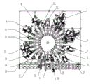
The utility model discloses an automatic welding, cutting and adhesive tape sticking device for a tab, which is used for packaging a lithium battery. The automatic welding, cutting and adhesive tape sticking device comprises a feeding device, a rotary table feeding device, a welding device, an adhesive tape sticking device and a blanking device, wherein the feeding device, the welding device, the adhesive tape sticking device and the blanking device are sequentially arranged around the rotary table feeding device; the feeding device comprises a feeding drawstring for transporting a cell and a feeding mechanical hand for gripping the cell and transporting the cell to the rotary table feeding device; the rotary table feeding device comprises a rotary table and a cam segmenting device which is arranged at the lower end of the center of the rotary table and used for driving the rotary table to rotate; the welding device comprises a pre-welding mechanism for adjusting the position of a welding head and welding parameters and a main welding mechanism which is arranged behind the pre-welding mechanism; a pre-welding test device and an after-welding test device are arranged in front of the welding device and behind the adhesive tape sticking device respectively. The automatic welding, cutting and adhesive tape sticking device can be used for automatically feeding and blanking, automatically welding and cutting the tab and automatically sticking the adhesive tape on the tab.
Description
Technical field
The invention belongs to lithium battery and manufacture field, relate to a kind of lug automatic welding, cut and rubberizing equipment.
Background technology
In current driving force battery production industry, lug prewelding and main weldering, tab cutting, lug pastes first and second road glue, and battery core test etc. is easy equipment and is completed by manual operations, and the battery precision of working it out is not like this very high, and outward appearance is very not attractive in appearance.Transfer number of times is too many, causes production capacity low, also can cause the waste on space.The research staff of lithium battery production equipment improves this, Chinese patent 201010234162.3 discloses a kind of method for assembling lugs of lithium ion battery, the method adopts artificial loading to fixture, battery core is fixed in fixture until complete rubberizing operation, improve to a certain extent the efficiency of battery production, but still have operation as artificial in employings such as rubberizings, can not realize comprehensive automation, and whole process is not welded front test, as defective battery core is welded to rubberizing, not only qualification rate is not high, and causes the waste in material and man-hour.
Summary of the invention
The object of the invention is the automation of producing in order to realize electrokinetic cell, and improve production capacity, guarantee precision, guarantee outward appearance, cut the waste, for industry manufacture provides full automatic production equipment, a kind of a kind of lug automatic welding that collects automatic loading/unloading, automatically tab welding, automatically tab cutting and lug rubberizing automatically is now provided, cuts and rubberizing equipment.
For achieving the above object, the invention provides a kind of lug automatic welding, cut and rubberizing equipment, comprise feeding device, rotating disk pay-off, welder, tape sticking device and blanking device, wherein: feeding device, welder, tape sticking device and blanking device are arranged in order around rotating disk pay-off; Feeding device comprises and transports the material loading drawstring of battery core and pick up battery core the power transmission core feeding manipulator to rotating disk pay-off; Rotating disk pay-off comprises that rotating disk and center of turntable lower end drive the Cam splitter of dial rotation; Welder comprises the prewelding mechanism of adjusting soldering tip position and welding parameter and is arranged in the main welding mechanism after prewelding mechanism; Before welder and after tape sticking device, be respectively equipped with the front testing apparatus of weldering and postwelding testing apparatus.
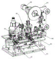
Prewelding mechanism is divided into anodal pre-welder and the pre-welder of negative pole, and main welding mechanism is divided into anodal main welder and the main welder of negative pole, and anodal pre-welder, the pre-welder of negative pole, anodal main welder and the main welder of negative pole are arranged in order on rotating disk pay-off; Described prewelding mechanism comprises lug upper holder block, adjusting screw(rod) and the jacking cylinder that the supersonic welder, lug upper holder block cylinder, the lug upper holder block cylinder lower end that are fixed on welding machine fixed head connect, adjusting screw(rod) and left and right adjusting screw rod before and after described adjusting screw(rod) comprises, described jacking cylinder upwards connects welding machine fixed head for controlling welding machine lifting, and lug upper holder block is positioned at the soldering tip place of supersonic welder; Described main welding mechanism is arranged in order setting by lug automatic feeding, lug automatic shaping and cutting means, lug automatic bending device, lug automatic soldering device.
Described tape sticking device is provided with first rubberizing system and second rubberizing system, first rubberizing system is divided into the anodal rubberizing system of first and first negative pole rubberizing system, second rubberizing system is divided into the anodal rubberizing system of second and second negative pole rubberizing system, wherein: the anodal rubberizing system of first is pasted just very " U " shape, it is " U " shape that first negative pole rubberizing system is pasted negative pole, the anodal rubberizing system of second is pasted just very " L " shape, and it is " L " shape that second negative pole rubberizing system is pasted negative pole; Each adhesive tape rubberizing mechanism comprises and automatically send glue and cut position, standby glue position and rubberizing position, automatically send glue and cut position is connected standby glue position for to standby glue position for glue, supply glue to rubberizing position for glue position.
Before first rubberizing system and between twice rubberizing system, be also provided with tab cutting device, described tab cutting device comprises upper cutter, lower cutter, line slide rail and front and back adjusting screw(rod), upper cutter cylinder, upper cutter, lower cutter, lower cutter cylinder are arranged from top to bottom successively in line slide rail one side, upper cutter and lower cutter relatively move and cut along line slide rail with upper cutter seat incision tool rest, the tab cutting extremely suitable length of described tab cutting device for welding is completed; Before first rubberizing system, be the first tab cutting device, for cutting tab welding end; Between twice rubberizing system is the second tab cutting device, for cutting the non-welding ends of lug.
Between tab cutting device before first rubberizing system and first rubberizing system, be also provided with the concora crush burr dust exhaust apparatus that siphons away dust for flattening burr, described concora crush burr dust exhaust apparatus comprises upper holder block, lower lock block, dust shield and upper holder block cylinder, lower lock block cylinder and line slide rail, described upper holder block and lower lock block are corresponding up and down, in the time of cylinder action, upper holder block and lower lock block relative motion flatten the burr of lug, dust shield is positioned at the side that top board is relative with battery core with lower platen, and described dust shield dust in the time of dust shield cylinder operation siphons away.
Between the first tab cutting device after first rubberizing system and first rubberizing system, be also provided with lug is converted into the lug apparatus for bending of certain angle for follow-up tab cutting and second rubberizing, described lug apparatus for bending comprises upper holder block, lower lock block, upper holder block cylinder, lower lock block cylinder, line slide rail and support, described line slide rail is fixed on support, upper holder block and lower lock block under the effect of upper holder block cylinder and lower lock block cylinder by the lug bending of battery core front end.
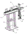
Described material loading drawstring is provided with the battery core detent mechanism for determining battery core position on material loading drawstring and detects battery core the inductor that whether arrives assigned address; On described material loading drawstring, be also provided with dust shield for guaranteeing the clean of supplied materials; Described feeding manipulator comprises the slide unit manipulator on robot support seat and first lift cylinder that can horizontally slip on slide unit manipulator, the second lift cylinder, points cylinder, compression cylinder and grip block, described grip block upper end connects compression cylinder, and compression cylinder upwards has finger cylinder, the second lift cylinder, the first lift cylinder successively; Described slide unit manipulator one end is also provided with servo motor.
Described rotating disk is two-layer, upper strata rotating disk is fixing rotating disk, lower floor's rotating disk is rotatable turntable, described fixing rotating disk is provided with on position corresponding to each station presses clamp cylinder to compress battery core when working, when described rotatable turntable is provided with work, the battery core fixture of transferable battery core is some, described Cam splitter drives rotatable turntable to rotate, and constantly battery core is sent into next station.
Described blanking device comprises blanking mechanical hand, NG blanking bench and blanking drawstring, and blanking mechanical hand is flexibly connected NG blanking bench and blanking drawstring; The end of described lower material strip and NG blanking bench is provided with inductor switch in order to point out battery core to arrive the end of blanking drawstring or NG blanking bench.
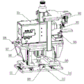
Before described feeding device and weldering, between testing apparatus, be also provided with apparatus for shaping, carry out shaping for the battery core that feeding device is brought; Described apparatus for shaping comprises portable plate, jacking cylinder, guide pillar, finger cylinder, side trim panel, prelocalization piece and shaping pushing block, portable plate lower end connects jacking cylinder and guide pillar, jacking cylinder upwards promotes portable plate, and when the linear bearing that the guide pillar that portable plate lower end is fixing and guide pillar run through moves up and down for controlling portable plate, direction is accurate; The finger cylinder of portable plate upper end is for controlling the position of side trim panel, and prelocalization piece stops battery core front end through side trim panel, and battery core shaping pushing block is below used for promoting battery core and in side trim panel, moves to prelocalization piece.
Equipment surrounding is provided with mobile control box communication interface and scram button.
Beneficial effect of the present invention is:
1, by detection, weld, cut, rubberizing operation is integrated on an equipment and completes, and realizes fully automatic working, improved product quality and guaranteed constant product quality.
2, adopt rotating disc type station transfer structure, loading and unloading, in same orientation, only need one man operation, have saved human cost.
3, in the multiple devices in present device, be provided with dust shield, improved the qualification rate of product in the course of processing.
4, in the present invention, be provided with automatic flat burr device, carry out concora crush burr than special equipment in existing production and saved man-hour, greatly increase work efficiency, reduced production cost.
5, in welder, be provided with adjusting screw(rod), facilitate the cutoff length of regulation and control soldering tip position and lug.
6, prewelding and main weldering arrange both positive and negative polarity 2 welding respectively, have guaranteed welding effect.
7, both positive and negative polarity 2 rubberizings are respectively set in tape sticking device, have guaranteed rubberizing effect.
8, compact conformation of the present invention, good looking appearance, each operation rational deployment, and also control button and instrument be all at suitable height, and equipment surrounding is equipped with control box communication interface and scram button, the personnel that are convenient to operation debugging.
Accompanying drawing explanation
Fig. 1 is lug automatic welding of the present invention, cut and the overall schematic of rubberizing equipment;
Fig. 2 is the material loading drawstring schematic diagram in Fig. 1;
Fig. 3 is lug automatic welding of the present invention, cut and the feeding manipulator schematic diagram of rubberizing equipment;
Fig. 4 is lug automatic welding of the present invention, cut and the rotating disk pay-off schematic diagram of rubberizing equipment;
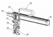
Fig. 5 is lug automatic welding of the present invention, cut and the pre-welder schematic diagram of rubberizing equipment;
Fig. 6 is lug automatic welding of the present invention, cut and the main welder schematic diagram of rubberizing equipment;
Fig. 7 is lug automatic welding of the present invention, cut and the upper tape sticking device schematic diagram of rubberizing equipment;
Fig. 8 is lug automatic welding of the present invention, cut and the tab cutting device schematic diagram of rubberizing equipment;
Fig. 9 is lug automatic welding of the present invention, cut and the concora crush burr dust exhaust apparatus schematic diagram of rubberizing equipment;
Figure 10 is lug automatic welding of the present invention, cut and the lug apparatus for bending schematic diagram of rubberizing equipment;
Figure 11 is lug automatic welding of the present invention, cut and the blanking mechanical hand schematic diagram of rubberizing equipment;
Figure 12 is lug automatic welding of the present invention, cut and the NG blanking bench schematic diagram of rubberizing equipment;
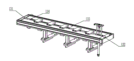
Figure 13 is lug automatic welding of the present invention, cut and the blanking drawstring schematic diagram of rubberizing equipment;
Figure 14 is lug automatic welding of the present invention, cut and the apparatus for shaping schematic diagram of rubberizing equipment;
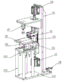
Figure 15 is lug automatic welding of the present invention, cut and the testing apparatus schematic diagram of rubberizing equipment;
Figure 16 is lug automatic welding of the present invention, cut and the lower bearing bracket schematic diagram of rubberizing equipment;
1, feeding manipulator; 2, material loading drawstring; 3, rotating disk pay-off; 4, anodal pre-welder; 5, the pre-welder of negative pole; 6, anodal main welder; 7, the main welder of negative pole; 8, the anodal rubberizing system of first; 9, first negative pole rubberizing system; 10, the anodal rubberizing system of second; 11, second negative pole rubberizing system; 12, the first tab cutting device; 13, the second tab cutting device; 14, concora crush burr dust exhaust apparatus; 15, lug apparatus for bending; 16, testing apparatus before weldering; 17, postwelding testing apparatus; 18, NG blanking bench; 19, blanking drawstring; 20, apparatus for shaping, 21, blanking mechanical hand; 201, inductor; 202, dust shield; 203, battery core locating piece; 204, battery core positioning strip; 205, drawstring supporting plate; 206, synchronous drawstring; 207, active synchronization wheel; 208, driven synchronizing wheel; 301, slide unit manipulator; 302, manipulator drag chain; 303, the first lift cylinder; 304 servo motors; 305, the second lift cylinder; 306, finger cylinder; 307, compression cylinder; 308, grip block; 309, robot support seat; 310, wire-passing tube; 311, manipulator angle bearing; 401, fixing rotating disk; 402, rotatable turntable; 403, press clamp cylinder; 404, battery core fixture; 405, wire casing; 406, wire casing support; Power motor; 408, regulating base board; 409, rotary disc alignment rod; 410, open gas enclosure cylinder; 501, supersonic welder; 502, lug upper holder block cylinder; 503, lug upper holder block; 504, inductor; 505, jacking cylinder; 506, front and back adjusting screw(rod); 507, welding machine fixed head; 508, welding machine back-up block; 509, left and right adjusting screw rod; 510, line slide rail; 511, ruler; 512, base plate; 601, lug automatic feeding; 602, lug automatic shaping and cutting means; 603, releasing bracket; 604, lug automatic bending device; 605, lug automatic soldering device; 606, lug turnover device; 607, tab welding support; 608, blowing motor; 701, automatically send glue and cut position; 702, standby glue position; 703, rubberizing position; 704, upper cutter cylinder; 705, upper cutter; 706, lower cutter; 707, line slide rail; 708, front and back adjusting screw(rod); 709, lower cutter cylinder; 710, waste material box; 711, base plate; 801, upper holder block cylinder; 802, upper holder block; 803, lower lock block; 804, lower lock block cylinder; 805, adjusting screw(rod); 806, support; 807, line slide rail; 808, dust shield; 809, base plate; 810, upper holder block cylinder; 811, upper holder block; 812, lower lock block; 813, lower lock block cylinder; 814, line slide rail; 815, support; 816, adjusting screw(rod); 817, base plate; 818, feather key; 901, slide unit manipulator; 902, manipulator lift cylinder; 903, servo motor; 904, the cylinder of setting a table; 905, finger cylinder; 906, compression cylinder; 907, manipulator drag chain; 908, grip block; 121, NG blanking plate; 122, support; 123, blanking battery core push pedal; 124, rib; 125, inductor; 131, driving wheel; 132, driven pulley; 133, belt; 134, inductor; 140, support; 141, prelocalization piece; 142, shaping pushing block; 143, side trim panel; 144, finger cylinder; 145, guide pillar; 146, linear bearing; 147, jacking cylinder; 148, jacking pushing block cylinder; 149, portable plate; 150, upper cylinder; 151, test bracket; 152, probe mounting blocks; 153, line slide rail; 154, test lower lock block; 155, lower lock block cylinder; 156, adjusting screw(rod); 157, battery core compression cylinder; 158, battery core supporting plate; 159, guide pillar; 1510, linear bearing; 1511, support; 1512, base plate; 161, belt lock plate door; 162, base plate; 163, lower bearing bracket; 164, sweep-up pipe; 165, wire-passing tube; 166, adjustment height universal caster wheel.
Embodiment
Below in conjunction with the drawings and specific embodiments, the present invention is described further.
As shown in Figure 1: a kind of lug automatic welding, cut and rubberizing equipment, comprise feeding device, rotating disk pay-off 3, welder, tape sticking device and blanking device, wherein: feeding device, welder, tape sticking device and blanking device are arranged in order around rotating disk pay-off 3; Feeding device comprise transport the material loading drawstring 2 of battery core and pick up battery core and power transmission core to the feeding manipulator 1 of rotating disk pay-off 3; Rotating disk pay-off 3 comprises that rotating disk and center of turntable lower end drive the Cam splitter of dial rotation; Welder comprises the prewelding mechanism of adjusting soldering tip position and welding parameter and is arranged in the main welding mechanism after prewelding mechanism; Before welder and after tape sticking device, be respectively equipped with the front testing apparatus 16 of weldering and postwelding testing apparatus 17.Prewelding mechanism is divided into anodal pre-welder 4 and the pre-welder 5 of negative pole, main welding mechanism is divided into anodal main welder 6 and the main welder 7 of negative pole, and anodal pre-welder 4, the pre-welder 5 of negative pole, anodal main welder 6 and the main welder 7 of negative pole are arranged in order on rotating disk pay-off 4;
As shown in Figure 1, Figure 2 and Figure 3: material loading drawstring is provided with the battery core detent mechanism for determining battery core position on material loading drawstring 2 and detects battery core the inductor 201 that whether arrives assigned address, and described battery core detent mechanism comprises battery core positioning strip 204 and is fixed on the battery core locating piece 203 on battery core positioning strip 204; Adjust battery core positioning strip 204 and battery core locating piece 203 according to the specification of battery core, make battery in tram; The lower end of material loading drawstring 2 tail ends is provided with jacking cylinder for by the battery core jack-up of material loading drawstring 2 tail ends; Battery core positioning strip 204 is evenly distributed on synchronous drawstring 206, and material loading drawstring 2 ends are provided with the active synchronization wheel 207 of servo motor driven, and active synchronization wheel 207 drives the driven synchronizing wheel 208 of the other end of material loading drawstring 2 that battery core is delivered to assigned address; Dust shield 202 is for guaranteeing the clean of supplied materials; Described feeding manipulator 1 comprises the slide unit manipulator 301 on robot support seat 309 and first lift cylinder 303 that can horizontally slip on slide unit manipulator 301, the second lift cylinder 305, points cylinder 306, compression cylinder 307 and grip block 308, described grip block 308 upper ends connect compression cylinder 307, and compression cylinder 307 upwards has finger cylinder 306, the second lift cylinder 305, the first lift cylinder 305 successively; Described slide unit manipulator 301 one end are also provided with servo motor 304 for power is provided.
As shown in Figure 1 and Figure 4: described rotating disk is two-layer, upper strata rotating disk is fixing rotating disk 401, lower floor's rotating disk is rotatable turntable 402, described fixing rotating disk 401 is provided with on position corresponding to each station presses clamp cylinder 403 to compress battery core when working, when described rotatable turntable 402 is provided with work, the battery core fixture 404 of transferable battery core is some, the Cam splitter of rotating disk below drives rotatable turntable 402 to rotate, and constantly battery core is sent into next station.
If Fig. 1, Fig. 5 are as shown in Fig. 6: as described in prewelding mechanism comprise lug upper holder block 503, adjusting screw(rod) and the jacking cylinder 505 that the supersonic welder 501, lug upper holder block cylinder 502, lug upper holder block cylinder 502 lower ends that are fixed on welding machine fixed head 507 are connected, adjusting screw(rod) 506 and left and right adjusting screw rod 509 before and after described adjusting screw(rod) comprises, described jacking cylinder 505 upwards connects welding machine fixed head 507 for controlling welding machine lifting, and lug upper holder block 503 is positioned at the soldering tip place of supersonic welder 501; Described main welding mechanism is arranged in order setting by lug automatic feeding 601, lug automatic shaping and cutting means 602, lug automatic bending device 604, lug automatic soldering device 605.
As shown in Figure 1 and Figure 7: described tape sticking device is provided with first rubberizing system and second rubberizing system, first rubberizing system is divided into the anodal rubberizing system 8 of first and first negative pole rubberizing system 9, second rubberizing system is divided into the anodal rubberizing system 10 of second and second negative pole rubberizing system 11, the anodal rubberizing system 8 of first is pasted just very " U " shape, first negative pole rubberizing system 9 is pasted negative pole for " U " shape, the anodal rubberizing system 10 of second is pasted just very " L " shape, and second negative pole rubberizing system 11 is pasted negative pole for " L " shape; Each adhesive tape rubberizing mechanism comprises and automatically send glue and cut position 701, standby glue position 702 and rubberizing position 703, automatically send glue and cut position 701 is connected standby glue position 702 for to standby glue position 702 for glue, supply glue for glue position 702 to rubberizing position 703.
Shown in figure Fig. 1 and Fig. 8: be also provided with tab cutting device before first rubberizing system and between twice rubberizing system, it before first rubberizing system, is the first tab cutting device 12, between twice rubberizing system is the second tab cutting device 13, described tab cutting device comprises upper cutter 705, lower cutter 706, line slide rail 707 and front and back adjusting screw(rod) 708, upper cutter cylinder 704, upper cutter 705, lower cutter 706, lower cutter cylinder 709 is arranged from top to bottom successively in line slide rail one side, upper cutter 705 and lower cutter 706 relatively move and cut along line slide rail 707 with upper cutter seat incision tool rest, the tab cutting extremely suitable length of described tab cutting device for welding is completed.
As shown in Fig. 1 and Fig. 9: be also provided with the concora crush burr dust exhaust apparatus 14 that siphons away dust for flattening burr between the tab cutting device before first rubberizing system and first rubberizing system, described concora crush burr dust exhaust apparatus 14 comprises upper holder block 802, lower lock block 803, dust shield 808 and upper holder block cylinder 801, lower lock block cylinder 804 and line slide rail 807, described upper holder block 802 and lower lock block are corresponding Shang Xia 803, in the time of cylinder action, upper holder block 802 and lower lock block 803 relative motions flatten the burr of lug, dust shield 808 is positioned at the side that top board 802 is relative with battery core with lower platen 803, described dust shield 808 dust in the time of dust shield cylinder operation siphons away.
As shown in Fig. 1 and Figure 10: be also provided with lug is converted into the lug apparatus for bending 15 of certain angle for follow-up tab cutting and second rubberizing between the first tab cutting device 12 after first rubberizing system and first rubberizing system, described lug apparatus for bending 15 comprises upper holder block 811, lower lock block 812, upper holder block cylinder 810, lower lock block cylinder 813, line slide rail 814 and support 815, described line slide rail 814 is fixed on support 815, upper holder block 811 and lower lock block 812 under the effect of upper holder block cylinder 810 and lower lock block cylinder 813 by the lug bending of battery core front end.
As shown in Fig. 1, Figure 11, Figure 12, Figure 13: as described in blanking device comprise blanking mechanical hand 21, NG blanking bench 18 and blanking drawstring 19, blanking mechanical hand 21 is flexibly connected NG blanking bench 18 and blanking drawstring 19; The end of described lower material strip 19 and NG blanking bench 18 is provided with inductor switch in order to point out battery core to arrive the end of blanking drawstring 19 or NG blanking bench 18.Blanking mechanical hand 21 comprises that one end is provided with the slide unit manipulator 901 of servo motor 903, slide unit manipulator 901 is provided with manipulator drag chain 907, one side of slide unit manipulator 901 is provided with manipulator lift cylinder 902, manipulator lift cylinder 902 is provided with the cylinder 904 of setting a table, finger cylinder 905 and compression cylinder 906 downwards successively, and the lower end of finger cylinder 905, a side of compression cylinder 906 are provided with grip block 908.NG blanking bench 18 comprises support 122, NG blanking plate 121, pusher cylinder, rib 124 and inductor 125, blanking mechanical hand 21 is placed NG battery core after NG blanking plate 121, the action of pusher cylinder is pushed battery core to NG blanking plate 121 ends, when battery core arrives NG blanking plate 121 end, inductor 125 is responded to, system alarm prompting.Blanking drawstring 19 is provided with governor motor, driving pulley 131, driven pulley 132, belt 133 and inductor 134, qualified product are placed blanking drawstring 19 by blanking mechanical hand 21, motor drives driving pulley 131 to drive belt 133 that battery core is thought to blanking drawstring 19 ends shift, in the time that battery core arrives drawstring 19 end, inductor 134 work system alarms.
As shown in Fig. 1 and Figure 14: be also provided with apparatus for shaping 20 between testing apparatus before feeding device and weldering, carry out shaping for the battery core that feeding device is brought; Apparatus for shaping 20 comprises portable plate 149, jacking cylinder 147, guide pillar 145, finger cylinder 144, side trim panel 143, prelocalization piece 141 and shaping pushing block 142, portable plate 149 lower ends connect jacking cylinder 147 and guide pillar 145, jacking cylinder 147 upwards promotes portable plate 149, and when the linear bearing 146 that the guide pillar 145 that portable plate 149 lower ends are fixing and guide pillar 145 run through moves up and down for controlling portable plate 149, direction is accurate; The finger cylinder 144 of portable plate 149 upper ends is for controlling the position of side trim panel 143, prelocalization piece 141 stops battery core front end through side trim panel 143, and battery core shaping pushing block 142 below moves to prelocalization piece 141 for promoting battery core in side trim panel 143.
As shown in Fig. 1 and Figure 15, testing apparatus comprises test lower lock block 154, probe, battery core supporting plate 158, adjusting screw(rod) 156, test bracket 151, guide pillar 159 and linear bearing 1510, before weldering, whether testing apparatus is qualified product for detection of supplied materials, defective follow-up station is not worked, in order to avoid waste resource; The whether conducting of lug after for detection of welding of postwelding test and battery core, if defective products, when blanking, automatic distinguishing arranges.
As shown in figure 16: the lower bearing bracket 163 of present device comprises: base plate 162, the sweep-up pipe 164 and the wire-passing tube 165 that project upwards through base plate 163, lower bearing bracket 163 lower ends are provided with adjustment height universal caster wheel 166.
Equipment surrounding is provided with mobile control box communication interface and scram button.
Workflow of the present invention is: a circulation of anodal rubberizing → the first negative pole road rubberizing → lug bending → the second tab cutting (non-the welding ends) → second anodal rubberizing → second negative pole rear test → blanking mechanical hand transfer battery core lower rotary table → blanking drawstring feeding of rubberizing → welding of test → anodal prewelding → negative pole prewelding → main weldering → the first tab cutting of anodal main weldering → negative pole (welding ends) → concora crush burr dust suction → first (or the feeding of NG blanking bench) before the position shaping → welding of battery core top rotary table → dial rotation feeding → battery core → complete is shifted in material loading drawstring feeding → feeding manipulator.
Certainly, above embodiment is merely illustrative and not limiting to the invention, the above is only preferred embodiment of the present invention, and the equivalence of doing according to the scheme described in patent claim of the present invention therefore all changes or modifies, and is included in patent claim of the present invention.
Claims (10)
- Lug automatic welding, cut and rubberizing equipment, comprise feeding device, rotating disk pay-off, welder, tape sticking device and blanking device, it is characterized in that: described feeding device, welder, tape sticking device and blanking device are arranged in order around rotating disk pay-off; Described feeding device comprises and transports the material loading drawstring of battery core and pick up battery core the power transmission core feeding manipulator to rotating disk pay-off; Described rotating disk pay-off comprises that rotating disk and center of turntable lower end drive the Cam splitter of dial rotation; Described welder comprises the prewelding mechanism of adjusting soldering tip position and welding parameter and is arranged in the main welding mechanism after prewelding mechanism; Before described welder and after tape sticking device, be respectively equipped with the front testing apparatus of weldering and postwelding testing apparatus.
- Lug automatic welding according to claim 1, cut and rubberizing equipment, it is characterized in that: prewelding mechanism is divided into anodal pre-welder and the pre-welder of negative pole, main welding mechanism is divided into anodal main welder and the main welder of negative pole, and anodal pre-welder, the pre-welder of negative pole, anodal main welder and the main welder of negative pole are arranged in order on rotating disk pay-off; Described prewelding mechanism comprises lug upper holder block, adjusting screw(rod) and the jacking cylinder that the supersonic welder, lug upper holder block cylinder, the lug upper holder block cylinder lower end that are fixed on welding machine fixed head connect, adjusting screw(rod) and left and right adjusting screw rod before and after described adjusting screw(rod) comprises, described jacking cylinder upwards connects welding machine fixed head for controlling welding machine lifting, and lug upper holder block is positioned at the soldering tip place of supersonic welder; Described main welding mechanism is arranged in order setting by lug automatic feeding, lug automatic shaping and cutting means, lug automatic bending device, lug automatic soldering device.
- 3. lug automatic welding according to claim 1, cut and rubberizing equipment, it is characterized in that: described tape sticking device is provided with first rubberizing system and second rubberizing system, first rubberizing system is divided into the anodal rubberizing system of first and first negative pole rubberizing system, second rubberizing system is divided into the anodal rubberizing system of second and second negative pole rubberizing system, the anodal rubberizing system of first is pasted just very " U " shape, it is " U " shape that first negative pole rubberizing system is pasted negative pole, the anodal rubberizing system of second is pasted just very " L " shape, it is " L " shape that second negative pole rubberizing system is pasted negative pole, each adhesive tape rubberizing mechanism comprises and automatically send glue and cut position, standby glue position and rubberizing position, automatically send glue and cut position is connected standby glue position for to standby glue position for glue, supply glue to rubberizing position for glue position.
- 4. lug automatic welding according to claim 3, cut and rubberizing equipment, it is characterized in that: before first rubberizing system and between twice rubberizing system, be also provided with tab cutting device, described tab cutting device comprises upper cutter, lower cutter, line slide rail and front and back adjusting screw(rod), upper cutter cylinder, upper cutter, lower cutter, lower cutter cylinder is arranged from top to bottom successively in line slide rail one side, upper cutter and lower cutter relatively move and cut along line slide rail with upper cutter seat incision tool rest, the tab cutting extremely suitable length of described tab cutting device for welding is completed, tab cutting device before first rubberizing system is the first tab cutting device, cuts for tab welding end, and the tab cutting device between twice rubberizing system is the second tab cutting device, for cutting the non-welding ends of lug.
- 5. lug automatic welding according to claim 4, cut and rubberizing equipment, it is characterized in that: between the tab cutting device before first rubberizing system and first rubberizing system, be also provided with the concora crush burr dust exhaust apparatus that siphons away dust for flattening burr, described concora crush burr dust exhaust apparatus comprises upper holder block, lower lock block, dust shield and upper holder block cylinder, lower lock block cylinder and line slide rail, described upper holder block and lower lock block are corresponding up and down, in the time of cylinder action, upper holder block and lower lock block relative motion flatten the burr of lug, dust shield is positioned at the side that top board is relative with battery core with lower platen, described dust shield dust in the time of dust shield cylinder operation siphons away.
- 6. lug automatic welding according to claim 4, cut and rubberizing equipment, it is characterized in that: between the first tab cutting device after first rubberizing system and first rubberizing system, be also provided with lug is converted into the lug apparatus for bending of certain angle for follow-up tab cutting and second rubberizing, described lug apparatus for bending comprises upper holder block, lower lock block, upper holder block cylinder, lower lock block cylinder, line slide rail and support, described line slide rail is fixed on support, upper holder block and lower lock block under the effect of upper holder block cylinder and lower lock block cylinder by the lug bending of battery core front end.
- Lug automatic welding according to claim 1, cut and rubberizing equipment, it is characterized in that: described material loading drawstring is provided with the battery core detent mechanism for determining battery core position on material loading drawstring and detects battery core the inductor that whether arrives assigned address; On described material loading drawstring, be also provided with dust shield for guaranteeing the clean of supplied materials; Described feeding manipulator comprises the slide unit manipulator on robot support seat and first lift cylinder that can horizontally slip on slide unit manipulator, the second lift cylinder, points cylinder, compression cylinder and grip block, described grip block upper end connects compression cylinder, and compression cylinder upwards has finger cylinder, the second lift cylinder, the first lift cylinder successively; Described slide unit manipulator one end is also provided with servo motor.
- Lug automatic welding according to claim 1, cut and rubberizing equipment, it is characterized in that: described rotating disk is two-layer, upper strata rotating disk is fixing rotating disk, lower floor's rotating disk is rotatable turntable, described fixing rotating disk is provided with on position corresponding to each station presses clamp cylinder to compress battery core when working, when described rotatable turntable is provided with work, the battery core fixture of transferable battery core is some, and described Cam splitter drives rotatable turntable to rotate.
- Lug automatic welding according to claim 1, cut and rubberizing equipment, it is characterized in that: described blanking device comprises blanking mechanical hand, NG blanking bench and blanking drawstring, blanking mechanical hand is flexibly connected NG blanking bench and blanking drawstring; The end of described lower material strip and NG blanking bench is provided with inductor switch in order to point out battery core to arrive the end of blanking drawstring or NG blanking bench.
- Lug automatic welding according to claim 1, cut and rubberizing equipment, it is characterized in that: before described feeding device and weldering, be also provided with apparatus for shaping between testing apparatus, carry out shaping for the battery core that feeding device is brought; Described apparatus for shaping comprises portable plate, jacking cylinder, guide pillar, finger cylinder, side trim panel, prelocalization piece and shaping pushing block, portable plate lower end connects jacking cylinder and guide pillar, jacking cylinder upwards promotes portable plate, and when the linear bearing that the guide pillar that portable plate lower end is fixing and guide pillar run through moves up and down for controlling portable plate, direction is accurate; The finger cylinder of portable plate upper end is for controlling the position of side trim panel, and prelocalization piece stops battery core front end through side trim panel, and battery core shaping pushing block is below used for promoting battery core and in side trim panel, moves to prelocalization piece.
Priority Applications (1)
| Application Number | Priority Date | Filing Date | Title |
|---|---|---|---|
| CN201320771641.8U CN203644864U (en) | 2013-11-29 | 2013-11-29 | Automatic welding, cutting and adhesive tape sticking device for tab |
Applications Claiming Priority (1)
| Application Number | Priority Date | Filing Date | Title |
|---|---|---|---|
| CN201320771641.8U CN203644864U (en) | 2013-11-29 | 2013-11-29 | Automatic welding, cutting and adhesive tape sticking device for tab |
Publications (1)
| Publication Number | Publication Date |
|---|---|
| CN203644864U true CN203644864U (en) | 2014-06-11 |
Family
ID=50876088
Family Applications (1)
| Application Number | Title | Priority Date | Filing Date |
|---|---|---|---|
| CN201320771641.8U Expired - Fee Related CN203644864U (en) | 2013-11-29 | 2013-11-29 | Automatic welding, cutting and adhesive tape sticking device for tab |
Country Status (1)
| Country | Link |
|---|---|
| CN (1) | CN203644864U (en) |
Cited By (41)
| Publication number | Priority date | Publication date | Assignee | Title |
|---|---|---|---|---|
| CN104332580A (en) * | 2014-10-17 | 2015-02-04 | 惠州亿纬锂能股份有限公司 | Automatic electrode slice current-collection and conductive tab welding equipment |
| CN104477463A (en) * | 2014-12-03 | 2015-04-01 | 惠州金源精密自动化设备有限公司 | Automatic packing machine |
| CN104600372A (en) * | 2015-02-10 | 2015-05-06 | 惠州市多科达科技有限公司 | Automatic lithium battery packaging line |
| CN104966808A (en) * | 2015-06-24 | 2015-10-07 | 合肥国轩高科动力能源股份公司 | Method for simultaneously controlling tape gumming and pole piece edge bulging on pole lug of battery pole piece |
| CN105014373A (en) * | 2015-07-28 | 2015-11-04 | 浙江大学台州研究院 | Automatic assembling device for electronic mosquito repellent components |
| CN105047981A (en) * | 2015-08-26 | 2015-11-11 | 深圳市誉辰自动化设备有限公司 | Automatic Mylar packaging and welding machine for power battery |
| CN105397326A (en) * | 2016-01-08 | 2016-03-16 | 东莞市爱康电子科技有限公司 | Lithium battery and PCB guard plate welding equipment |
| CN105479175A (en) * | 2016-01-30 | 2016-04-13 | 杨金芝 | Automatic conducting strip sticking, welding and bending equipment and machining technology thereof |
| CN105826591A (en) * | 2016-04-11 | 2016-08-03 | 浙江超威创元实业有限公司 | Processing device and processing method for battery cell tab |
| CN105817823A (en) * | 2016-04-11 | 2016-08-03 | 广东鸿宝科技有限公司 | Battery cell clamp pushing device and automatic welding machine with pushing device |
| CN106384836A (en) * | 2015-11-19 | 2017-02-08 | 广东鸿宝科技有限公司 | Automatic adhesive-applying and automatic retainer-buckling apparatus for power battery |
| CN106450485A (en) * | 2016-12-15 | 2017-02-22 | 苏州猎奇智能设备有限公司 | Power lithium battery cell processing device |
| CN106711494A (en) * | 2016-11-12 | 2017-05-24 | 广东鸿宝科技有限公司 | Final welding device for power batteries |
| CN106784982A (en) * | 2017-03-20 | 2017-05-31 | 惠州市德赛自动化技术有限公司 | A kind of battery production technology of production line for manufacturing battery and the above-mentioned production line for manufacturing battery of application |
| CN106816624A (en) * | 2016-12-13 | 2017-06-09 | 广东鸿宝科技有限公司 | Electrokinetic cell automatic rubberizing, bending, button retainer device |
| CN106848371A (en) * | 2016-11-12 | 2017-06-13 | 广东鸿宝科技有限公司 | Electrokinetic cell automatic welding production line |
| CN106829463A (en) * | 2016-11-10 | 2017-06-13 | 广东鸿宝科技有限公司 | The automatic loading and unloading device of electrokinetic cell production line |
| CN107452979A (en) * | 2017-08-22 | 2017-12-08 | 东莞市普华精密机械有限公司 | A kind of soft package lithium battery cathode tab welds rubberizing paper equipment |
| CN107464957A (en) * | 2017-09-11 | 2017-12-12 | 珠海科斯特电源有限公司 | Poly-lithium battery automatic production line |
| CN107571025A (en) * | 2017-09-28 | 2018-01-12 | 海目星(江门)激光智能装备有限公司 | A kind of cell polar ear welding processing equipment |
| CN107634269A (en) * | 2017-09-15 | 2018-01-26 | 东莞市中造新材料科技有限公司 | A kind of lug glue plastering machine |
| CN107819145A (en) * | 2016-09-14 | 2018-03-20 | 惠州市德赛自动化技术有限公司 | A kind of automatic mobile phone battery core production line |
| CN107819142A (en) * | 2016-09-14 | 2018-03-20 | 惠州市德赛自动化技术有限公司 | A kind of automatic cutter |
| CN107819144A (en) * | 2016-09-14 | 2018-03-20 | 惠州市德赛自动化技术有限公司 | A kind of automatic charging guillotine |
| CN107813074A (en) * | 2016-09-14 | 2018-03-20 | 惠州市德赛自动化技术有限公司 | A kind of automatic welding machine |
| CN107994263A (en) * | 2018-01-15 | 2018-05-04 | 惠州市恒泰科技股份有限公司 | A kind of battery pole ear rubberizing folds all-in-one machine |
| CN108123092A (en) * | 2017-12-21 | 2018-06-05 | 梁叶青 | A kind of polar-ear gluing device |
| CN108258321A (en) * | 2017-12-13 | 2018-07-06 | 深圳市联赢激光股份有限公司 | A kind of electrical core of power battery automatic matching machine |
| CN108339888A (en) * | 2018-02-23 | 2018-07-31 | 郑州鹏润实业有限公司 | A kind of full-automatic battery lug shaping cutting apparatus |
| CN108598548A (en) * | 2018-06-25 | 2018-09-28 | 深圳市协联众创科技有限公司 | A kind of rotating disc type all-in-one machine |
| CN108890311A (en) * | 2018-09-06 | 2018-11-27 | 南通市华冠电器有限公司 | Water level sensor capacitor shield coil welder |
| CN108923222A (en) * | 2018-08-16 | 2018-11-30 | 东莞市信为兴电子有限公司 | A kind of automatic patch mark drawing device |
| CN109119587A (en) * | 2018-10-28 | 2019-01-01 | 深圳市兴禾自动化有限公司 | A kind of cell polar ear automatic welding is cut, rubberizing and bending production line and its production technology |
| CN109473712A (en) * | 2018-11-26 | 2019-03-15 | 惠州锂威新能源科技有限公司 | A kind of lithium-ion electric core airbag is anti-to be can't cut device and prevents the method that can't cut |
| CN109676254A (en) * | 2019-02-25 | 2019-04-26 | 江苏九蓝新能源科技有限公司 | A kind of disc type aluminium-to-nickel tab welding equipment |
| CN109802087A (en) * | 2019-03-08 | 2019-05-24 | 广东利元亨智能装备股份有限公司 | A kind of tab welding molding machine |
| WO2019109303A1 (en) * | 2017-12-07 | 2019-06-13 | 惠州市成泰自动化科技有限公司 | Electrode tab shaping machine |
| CN110350138A (en) * | 2019-07-22 | 2019-10-18 | 昆山华誉自动化科技有限公司 | A kind of folded pre- welder of core tab |
| CN110449896A (en) * | 2019-08-22 | 2019-11-15 | 中车青岛四方车辆研究所有限公司 | Tab transport device and tab welding production line |
| CN110640284A (en) * | 2019-10-28 | 2020-01-03 | 周强 | Automatic pre-welding machine for welding brush braid of motor carbon brush |
| CN112652845A (en) * | 2020-12-21 | 2021-04-13 | 深圳市泽诚自动化设备有限公司 | Preparation method and equipment of soft package battery |
-
2013
- 2013-11-29 CN CN201320771641.8U patent/CN203644864U/en not_active Expired - Fee Related
Cited By (61)
| Publication number | Priority date | Publication date | Assignee | Title |
|---|---|---|---|---|
| CN104332580B (en) * | 2014-10-17 | 2017-01-18 | 惠州亿纬锂能股份有限公司 | Automatic electrode slice current-collection and conductive tab welding equipment |
| CN104332580A (en) * | 2014-10-17 | 2015-02-04 | 惠州亿纬锂能股份有限公司 | Automatic electrode slice current-collection and conductive tab welding equipment |
| CN104477463A (en) * | 2014-12-03 | 2015-04-01 | 惠州金源精密自动化设备有限公司 | Automatic packing machine |
| CN104477463B (en) * | 2014-12-03 | 2017-08-25 | 惠州金源精密自动化设备有限公司 | automatic packaging machine |
| CN104600372A (en) * | 2015-02-10 | 2015-05-06 | 惠州市多科达科技有限公司 | Automatic lithium battery packaging line |
| CN104966808A (en) * | 2015-06-24 | 2015-10-07 | 合肥国轩高科动力能源股份公司 | Method for simultaneously controlling tape gumming and pole piece edge bulging on pole lug of battery pole piece |
| CN105014373A (en) * | 2015-07-28 | 2015-11-04 | 浙江大学台州研究院 | Automatic assembling device for electronic mosquito repellent components |
| CN105047981A (en) * | 2015-08-26 | 2015-11-11 | 深圳市誉辰自动化设备有限公司 | Automatic Mylar packaging and welding machine for power battery |
| CN106384836B (en) * | 2015-11-19 | 2023-09-05 | 广东鸿宝科技有限公司 | Automatic rubberizing and automatic buckle holder device of power battery |
| CN106384836A (en) * | 2015-11-19 | 2017-02-08 | 广东鸿宝科技有限公司 | Automatic adhesive-applying and automatic retainer-buckling apparatus for power battery |
| CN105397326B (en) * | 2016-01-08 | 2017-06-30 | 东莞市爱康电子科技有限公司 | Lithium battery and PCB protection board welding equipments |
| CN105397326A (en) * | 2016-01-08 | 2016-03-16 | 东莞市爱康电子科技有限公司 | Lithium battery and PCB guard plate welding equipment |
| CN105479175A (en) * | 2016-01-30 | 2016-04-13 | 杨金芝 | Automatic conducting strip sticking, welding and bending equipment and machining technology thereof |
| CN105817823A (en) * | 2016-04-11 | 2016-08-03 | 广东鸿宝科技有限公司 | Battery cell clamp pushing device and automatic welding machine with pushing device |
| CN105826591A (en) * | 2016-04-11 | 2016-08-03 | 浙江超威创元实业有限公司 | Processing device and processing method for battery cell tab |
| CN105826591B (en) * | 2016-04-11 | 2018-05-04 | 浙江超威创元实业有限公司 | Cell polar ear processing unit (plant) and processing method |
| CN107819145B (en) * | 2016-09-14 | 2023-12-26 | 惠州市德赛自动化技术有限公司 | Automatic mobile phone battery production line |
| CN107819145A (en) * | 2016-09-14 | 2018-03-20 | 惠州市德赛自动化技术有限公司 | A kind of automatic mobile phone battery core production line |
| CN107819144B (en) * | 2016-09-14 | 2023-12-26 | 惠州市德赛自动化技术有限公司 | Automatic feeding cutting machine |
| CN107819142B (en) * | 2016-09-14 | 2024-03-12 | 惠州市德赛自动化技术有限公司 | Automatic cutting machine |
| CN107813074A (en) * | 2016-09-14 | 2018-03-20 | 惠州市德赛自动化技术有限公司 | A kind of automatic welding machine |
| CN107819144A (en) * | 2016-09-14 | 2018-03-20 | 惠州市德赛自动化技术有限公司 | A kind of automatic charging guillotine |
| CN107819142A (en) * | 2016-09-14 | 2018-03-20 | 惠州市德赛自动化技术有限公司 | A kind of automatic cutter |
| CN106829463A (en) * | 2016-11-10 | 2017-06-13 | 广东鸿宝科技有限公司 | The automatic loading and unloading device of electrokinetic cell production line |
| CN106848371B (en) * | 2016-11-12 | 2023-09-05 | 广东鸿宝科技有限公司 | Automatic welding production line for power battery |
| CN106711494A (en) * | 2016-11-12 | 2017-05-24 | 广东鸿宝科技有限公司 | Final welding device for power batteries |
| CN106848371A (en) * | 2016-11-12 | 2017-06-13 | 广东鸿宝科技有限公司 | Electrokinetic cell automatic welding production line |
| CN106816624B (en) * | 2016-12-13 | 2023-05-12 | 广东鸿宝科技有限公司 | Automatic rubberizing, bending and buckling retainer device for power battery |
| CN106816624A (en) * | 2016-12-13 | 2017-06-09 | 广东鸿宝科技有限公司 | Electrokinetic cell automatic rubberizing, bending, button retainer device |
| CN106450485A (en) * | 2016-12-15 | 2017-02-22 | 苏州猎奇智能设备有限公司 | Power lithium battery cell processing device |
| CN106450485B (en) * | 2016-12-15 | 2023-08-08 | 苏州猎奇智能设备有限公司 | Power lithium battery cell processing apparatus |
| CN106784982A (en) * | 2017-03-20 | 2017-05-31 | 惠州市德赛自动化技术有限公司 | A kind of battery production technology of production line for manufacturing battery and the above-mentioned production line for manufacturing battery of application |
| CN106784982B (en) * | 2017-03-20 | 2023-08-25 | 惠州市德赛自动化技术有限公司 | Battery production line and battery production process using same |
| CN107452979A (en) * | 2017-08-22 | 2017-12-08 | 东莞市普华精密机械有限公司 | A kind of soft package lithium battery cathode tab welds rubberizing paper equipment |
| CN107452979B (en) * | 2017-08-22 | 2023-05-05 | 东莞市普华精密机械有限公司 | Soft packet of lithium cell tab welding gummed paper equipment |
| CN107464957B (en) * | 2017-09-11 | 2023-04-14 | 珠海冠宇电源有限公司 | Full-automatic production line of polymer lithium battery |
| CN107464957A (en) * | 2017-09-11 | 2017-12-12 | 珠海科斯特电源有限公司 | Poly-lithium battery automatic production line |
| CN107634269B (en) * | 2017-09-15 | 2023-11-24 | 东莞市中造新材料科技有限公司 | Tab rubberizing machine |
| CN107634269A (en) * | 2017-09-15 | 2018-01-26 | 东莞市中造新材料科技有限公司 | A kind of lug glue plastering machine |
| CN107571025A (en) * | 2017-09-28 | 2018-01-12 | 海目星(江门)激光智能装备有限公司 | A kind of cell polar ear welding processing equipment |
| WO2019109303A1 (en) * | 2017-12-07 | 2019-06-13 | 惠州市成泰自动化科技有限公司 | Electrode tab shaping machine |
| CN108258321A (en) * | 2017-12-13 | 2018-07-06 | 深圳市联赢激光股份有限公司 | A kind of electrical core of power battery automatic matching machine |
| CN108258321B (en) * | 2017-12-13 | 2023-08-29 | 深圳市联赢激光股份有限公司 | Automatic power battery cell pairing machine |
| CN108123092B (en) * | 2017-12-21 | 2020-08-28 | 宁波捷傲创益新材料有限公司 | Utmost point ear rubber coating device |
| CN108123092A (en) * | 2017-12-21 | 2018-06-05 | 梁叶青 | A kind of polar-ear gluing device |
| CN107994263B (en) * | 2018-01-15 | 2024-03-29 | 惠州市恒泰科技股份有限公司 | Battery tab rubberizing folding all-in-one |
| CN107994263A (en) * | 2018-01-15 | 2018-05-04 | 惠州市恒泰科技股份有限公司 | A kind of battery pole ear rubberizing folds all-in-one machine |
| CN108339888A (en) * | 2018-02-23 | 2018-07-31 | 郑州鹏润实业有限公司 | A kind of full-automatic battery lug shaping cutting apparatus |
| CN108598548A (en) * | 2018-06-25 | 2018-09-28 | 深圳市协联众创科技有限公司 | A kind of rotating disc type all-in-one machine |
| CN108923222B (en) * | 2018-08-16 | 2024-01-09 | 东莞市信为兴电子有限公司 | Automatic mark pasting and pulling device |
| CN108923222A (en) * | 2018-08-16 | 2018-11-30 | 东莞市信为兴电子有限公司 | A kind of automatic patch mark drawing device |
| CN108890311A (en) * | 2018-09-06 | 2018-11-27 | 南通市华冠电器有限公司 | Water level sensor capacitor shield coil welder |
| CN109119587A (en) * | 2018-10-28 | 2019-01-01 | 深圳市兴禾自动化有限公司 | A kind of cell polar ear automatic welding is cut, rubberizing and bending production line and its production technology |
| CN109473712A (en) * | 2018-11-26 | 2019-03-15 | 惠州锂威新能源科技有限公司 | A kind of lithium-ion electric core airbag is anti-to be can't cut device and prevents the method that can't cut |
| CN109676254B (en) * | 2019-02-25 | 2023-09-22 | 江苏九蓝新能源科技有限公司 | Disc type aluminum-nickel tab welding equipment |
| CN109676254A (en) * | 2019-02-25 | 2019-04-26 | 江苏九蓝新能源科技有限公司 | A kind of disc type aluminium-to-nickel tab welding equipment |
| CN109802087A (en) * | 2019-03-08 | 2019-05-24 | 广东利元亨智能装备股份有限公司 | A kind of tab welding molding machine |
| CN110350138A (en) * | 2019-07-22 | 2019-10-18 | 昆山华誉自动化科技有限公司 | A kind of folded pre- welder of core tab |
| CN110449896A (en) * | 2019-08-22 | 2019-11-15 | 中车青岛四方车辆研究所有限公司 | Tab transport device and tab welding production line |
| CN110640284A (en) * | 2019-10-28 | 2020-01-03 | 周强 | Automatic pre-welding machine for welding brush braid of motor carbon brush |
| CN112652845A (en) * | 2020-12-21 | 2021-04-13 | 深圳市泽诚自动化设备有限公司 | Preparation method and equipment of soft package battery |
Similar Documents
| Publication | Publication Date | Title |
|---|---|---|
| CN203644864U (en) | Automatic welding, cutting and adhesive tape sticking device for tab | |
| CN206493026U (en) | Electrokinetic cell lug prewelding device | |
| CN102709782B (en) | Multifunctional full automatic wire ranging terminal pressing machine | |
| CN202839322U (en) | Automatic connection piece splicing machine | |
| CN204639615U (en) | The one-body molded machining center of tubing based on Internet of Things Intelligent Manufacturing Technology | |
| CN107598581B (en) | Equipment for welding lug at bottom of battery cell and steel shell | |
| CN102398107A (en) | Full-automatic door body butt-welding machine | |
| CN203690413U (en) | Soft-package battery packaging production line | |
| CN102879759A (en) | Automatic wire-feeding, sealing and calibrating equipment and method of power metering device | |
| CN105729247A (en) | Vertical processing center machine tool with flexible material conveying function and use method thereof | |
| CN107452979A (en) | A kind of soft package lithium battery cathode tab welds rubberizing paper equipment | |
| CN202712311U (en) | Welding machine for cylindrical battery cap | |
| CN202749469U (en) | Lamination stacking machine material taking mechanism | |
| CN102689095B (en) | A kind of Full-automatic laser welder device and operational method | |
| CN2684382Y (en) | Auxiliary device for laser welding of battery body case | |
| CN104362384A (en) | Double-station laminating device and double-station laminating method | |
| CN105690091B (en) | Power battery fully-automatic production robot system | |
| CN202684202U (en) | Workpiece cutting device | |
| CN203679405U (en) | Automatic cutting machine | |
| CN202639681U (en) | Single-welding and serial-welding integrated equipment of solar cell piece | |
| CN207068999U (en) | A kind of soft package lithium battery cathode tab welds rubberizing paper equipment | |
| CN110137862A (en) | A kind of semi-automatic harness peeling machine | |
| CN203679396U (en) | Automatic feeding and cutting mechanism | |
| CN202070859U (en) | Right-angle automatic welder of bus bar | |
| CN205184245U (en) | Full automatic assembly equipment of christmas lamp holder cluster |
Legal Events
| Date | Code | Title | Description |
|---|---|---|---|
| C14 | Grant of patent or utility model | ||
| GR01 | Patent grant | ||
| CF01 | Termination of patent right due to non-payment of annual fee | ||
| CF01 | Termination of patent right due to non-payment of annual fee |
Granted publication date: 20140611 Termination date: 20181129 |