CN106816624B - Automatic rubberizing, bending and buckling retainer device for power battery - Google Patents
Automatic rubberizing, bending and buckling retainer device for power battery Download PDFInfo
- Publication number
- CN106816624B CN106816624B CN201710157656.8A CN201710157656A CN106816624B CN 106816624 B CN106816624 B CN 106816624B CN 201710157656 A CN201710157656 A CN 201710157656A CN 106816624 B CN106816624 B CN 106816624B
- Authority
- CN
- China
- Prior art keywords
- rubberizing
- battery cell
- buckling
- bending
- retainer
- Prior art date
- Legal status (The legal status is an assumption and is not a legal conclusion. Google has not performed a legal analysis and makes no representation as to the accuracy of the status listed.)
- Active
Links
Images


Classifications
-
- H—ELECTRICITY
- H01—ELECTRIC ELEMENTS
- H01M—PROCESSES OR MEANS, e.g. BATTERIES, FOR THE DIRECT CONVERSION OF CHEMICAL ENERGY INTO ELECTRICAL ENERGY
- H01M10/00—Secondary cells; Manufacture thereof
- H01M10/04—Construction or manufacture in general
- H01M10/0404—Machines for assembling batteries
-
- H—ELECTRICITY
- H01—ELECTRIC ELEMENTS
- H01M—PROCESSES OR MEANS, e.g. BATTERIES, FOR THE DIRECT CONVERSION OF CHEMICAL ENERGY INTO ELECTRICAL ENERGY
- H01M50/00—Constructional details or processes of manufacture of the non-active parts of electrochemical cells other than fuel cells, e.g. hybrid cells
- H01M50/50—Current conducting connections for cells or batteries
- H01M50/531—Electrode connections inside a battery casing
-
- Y—GENERAL TAGGING OF NEW TECHNOLOGICAL DEVELOPMENTS; GENERAL TAGGING OF CROSS-SECTIONAL TECHNOLOGIES SPANNING OVER SEVERAL SECTIONS OF THE IPC; TECHNICAL SUBJECTS COVERED BY FORMER USPC CROSS-REFERENCE ART COLLECTIONS [XRACs] AND DIGESTS
- Y02—TECHNOLOGIES OR APPLICATIONS FOR MITIGATION OR ADAPTATION AGAINST CLIMATE CHANGE
- Y02E—REDUCTION OF GREENHOUSE GAS [GHG] EMISSIONS, RELATED TO ENERGY GENERATION, TRANSMISSION OR DISTRIBUTION
- Y02E60/00—Enabling technologies; Technologies with a potential or indirect contribution to GHG emissions mitigation
- Y02E60/10—Energy storage using batteries
-
- Y—GENERAL TAGGING OF NEW TECHNOLOGICAL DEVELOPMENTS; GENERAL TAGGING OF CROSS-SECTIONAL TECHNOLOGIES SPANNING OVER SEVERAL SECTIONS OF THE IPC; TECHNICAL SUBJECTS COVERED BY FORMER USPC CROSS-REFERENCE ART COLLECTIONS [XRACs] AND DIGESTS
- Y02—TECHNOLOGIES OR APPLICATIONS FOR MITIGATION OR ADAPTATION AGAINST CLIMATE CHANGE
- Y02P—CLIMATE CHANGE MITIGATION TECHNOLOGIES IN THE PRODUCTION OR PROCESSING OF GOODS
- Y02P70/00—Climate change mitigation technologies in the production process for final industrial or consumer products
- Y02P70/50—Manufacturing or production processes characterised by the final manufactured product
Abstract
The invention discloses an automatic rubberizing, bending and retainer buckling device for a power battery, which comprises a turntable, wherein a plurality of sets of battery core clamps are arranged at the edge of the turntable, and a battery core feeding unit, a negative electrode tab rubberizing unit, a positive electrode tab rubberizing unit, a rubberizing defect detecting unit, a tab bending unit, a retainer buckling unit and a battery core blanking unit are sequentially arranged along the circumference of the turntable; the battery cell feeding unit is provided with a battery cell feeding pull belt and a battery cell feeding manipulator used for transferring the battery cells on the battery cell feeding pull belt to a battery cell clamp of the turntable; the battery cell blanking unit is provided with a battery cell blanking pull belt, an NG buffer pull belt and a battery cell blanking manipulator for transferring the battery cell autorotation disc to the battery cell blanking pull belt or the NG buffer pull belt. The invention realizes the full automation of the power battery rubberizing, bending and buckling retainer, reduces the influence of human factors, ensures the quality of the battery cell rubberizing, bending and buckling retainer, and improves the production efficiency of the power battery.
Description
Technical Field
The invention relates to the technical field of power battery production equipment, in particular to an automatic rubberizing, bending and buckling retainer device for a power battery.
Background
After ultrasonic welding of the battery cell tab and the battery cover plate is completed, the upper and lower welding positions of the battery cell tab need to be protected by pasting flat glue, meanwhile, as the tab material is softer, if no object is supported, the battery cell can move back and forth in the shell along the installation direction, contact collision between the tab and the battery shell or between the tab and the battery cover plate is easy to be caused, so that the tab is damaged, the discharging process is unstable or short-circuited, and the like. In the prior art, each procedure is generally carried out separately, manual operation is mainly adopted during rubberizing, human resources are consumed greatly, productivity is low, production cost is high, and when the battery cell is manually operated, the battery cell is inevitably contacted by workers, so that pollutants such as sweat and the like are easily left on the battery cell, and quality problems are easily generated; moreover, the existing mechanical equipment is low in degree of automation, so that the consistency and stability of the battery quality are poor, the yield is low, shutdown and material replacement are needed, the production efficiency is affected, and the production cost is too high.
Disclosure of Invention
The invention provides an automatic rubberizing, bending and buckling retainer device for a power battery, which aims at the defects in the prior art and can improve the production efficiency and the product quality of the battery.
In order to achieve the above purpose, the present invention adopts the following technical scheme:
the automatic rubberizing, bending and buckling retainer device for the power battery comprises a rotary table, wherein a plurality of sets of battery core clamps used for fixing battery cores are arranged at the edge of the rotary table, and a battery core feeding unit, a negative electrode tab rubberizing unit, a positive electrode tab rubberizing unit, a rubberizing failure detection unit, a tab bending unit, a buckling retainer unit and a battery core blanking unit are sequentially arranged along the circumference of the rotary table;
the battery cell feeding unit is provided with a battery cell feeding pull belt and a battery cell feeding manipulator used for transferring the battery cells on the battery cell feeding pull belt to a battery cell clamp of the turntable; the negative electrode tab rubberizing unit and the positive electrode tab rubberizing unit are respectively provided with rubberizing mechanisms, the rubberizing mechanisms comprise rubberizing mechanisms for rubberizing adhesive tapes on the upper surfaces of the battery cell tabs and rubberizing mechanisms for rubberizing adhesive tapes on the lower surfaces of the battery cell tabs, and the rubberizing mechanisms are respectively symmetrically arranged on the upper side and the lower side of the to-be-rubberized tab; the poor rubberizing detection unit is provided with a rubberizing detection system for detecting whether the tab rubberizes or not; the tab bending unit is provided with a bending mechanism for bending the tab by a certain angle and a bending material taking manipulator for transferring the battery core on the turntable to the bending mechanism; the retainer feeding mechanism and the buckling mechanism are used for buckling the retainer conveyed by the retainer feeding mechanism to the battery cell; the battery cell blanking unit is provided with a battery cell blanking pull belt, an NG buffer pull belt and a battery cell blanking manipulator for transferring the battery cell autorotation disc to the battery cell blanking pull belt or the NG buffer pull belt.
As a preferred scheme, the electric core fixture comprises an electric core tray and a clamping assembly for fixing an electric core on the electric core tray, the clamping assembly comprises two electric core clamping blocks which can be opened and closed relatively, a clamping block mounting seat for mounting the electric core clamping blocks and a first reset mechanism for enabling the two electric core clamping blocks to always have clamping trends, the electric core clamping blocks are provided with vertical supporting arms, electric core pressing plates transversely extending from the upper ends of the supporting arms and rocker arms obliquely extending from the inner sides of the lower ends of the self-supporting arms, the two electric core clamping blocks are symmetrically arranged on the left side and the right side of the electric core tray respectively, the electric core pressing plates are located above the electric core tray, the lower ends of the two rocker arms are respectively connected with the clamping block mounting seat located below the electric core tray in a rotating mode, guide bearing seats for expanding the two electric core clamping blocks are fixedly arranged below the electric core tray, two ends of the guide bearing seats are respectively provided with guide bearings in rolling contact with the inner side faces of the rocker arms on the two sides, and the lower side of the electric core tray is also provided with a second reset mechanism for enabling the electric core pressing plates to always have the second reset trend on the upper surfaces of the electric core.
As a preferable scheme, the first reset mechanism is two tension springs, a hanging hole for installing the tension springs is formed in the side face of the guide bearing seat, a pin shaft for installing the tension springs is arranged on the side face of the rocker arm, one end of the tension springs is connected with the hanging hole on the guide bearing seat during assembly, and the other end of the tension springs is connected with the pin shaft on the rocker arm.
As a preferred scheme, the fixed guide bar that stretches out downwards that is equipped with on the guide bearing frame, be equipped with the guide sleeve with the guide bar adaptation on the clamp splice mount pad, the clamp splice mount pad passes through the guide sleeve cover in guide bar outside movable mounting on the guide bar, the lower extreme of guide bar is equipped with the spacing ring that prevents clamp splice mount pad and drop out downwards, second canceling release mechanical system is a compression spring, compression spring locates between guide bearing frame and the clamp splice mount pad.
As a preferable scheme, the rubberizing mechanism comprises a rubberizing module, a rubberizing mechanism for pulling out the adhesive tape on the rubberizing module, a rubberizing mechanism for cutting off the adhesive tape pulled out by the rubberizing mechanism, and a rubberizing manipulator for sticking the cut adhesive tape to the upper surface of the battery lug; the adhesive sticking and discharging mechanism comprises a lower adhesive changing module, a lower adhesive pulling mechanism for pulling out the adhesive tape on the lower adhesive changing module, a lower adhesive cutting mechanism for cutting off the adhesive tape pulled out by the lower adhesive pulling mechanism, and a lower adhesive sticking manipulator for sticking the cut adhesive tape to the lower surface of the tab.
As a preferable scheme, the upper glue pulling mechanism and the lower glue pulling mechanism comprise a glue pulling support, a glue pulling sliding seat and a glue pulling clamping finger, wherein the glue pulling sliding seat is movably arranged on the glue pulling support and can be driven to slide left and right by a glue pulling motor fixedly arranged on the glue pulling support, and the glue pulling clamping finger is arranged on the glue pulling sliding seat and can be driven to open and close by a clamping finger cylinder fixedly arranged on the glue pulling sliding seat.
As a preferable scheme, the upper rubberizing manipulator and the lower rubberizing manipulator comprise rubberizing installation seats, rubberizing Y-axis modules, rubberizing Y-axis servo motors, rubberizing Z-axis modules, rubberizing Z-axis servo motors, rubberizing X-axis sliding table cylinders, opposite-rubberizing pressing blocks and rubberizing discs; the rubberizing Y-axis module is fixedly arranged on the rubberizing mounting seat, and the rubberizing Z-axis module is arranged on the rubberizing Y-axis module and can be driven by a rubberizing Y-axis servo motor to move left and right; the rubberizing X-axis sliding table cylinder is arranged on the rubberizing Z-axis servo motor and can be driven by the rubberizing Z-axis servo motor to move up and down; the adhesive suction disc, the opposite-pasting pressing block and the opposite-pasting sliding table cylinder are arranged on the adhesive pasting X-axis sliding table cylinder and can be driven by the adhesive pasting X-axis sliding table cylinder to move back and forth; the number of the opposite-sticking pressing blocks is two, and the opposite-sticking pressing blocks are respectively arranged on the front side and the rear side of the glue sucking disc and can be driven by the opposite-sticking sliding table cylinder to move up and down.
As a preferred scheme, go up bale splitter and bale splitter all include cutter cylinder block, go up cutter holder, go up cutter cylinder, lower cutter holder and lower cutter cylinder, go up cutter cylinder and lower cutter cylinder fixed mounting on cutter cylinder block, go up cutter holder and last cutter cylinder and be connected to can be driven by last cutter cylinder and reciprocate, lower cutter holder and lower cutter cylinder are connected to can be driven by lower cutter cylinder and reciprocate, go up cutter and lower cutter and install respectively on last cutter holder and lower cutter holder to go up the cutter and laminating each other with the opposite face of lower cutter.
As a preferable scheme, the bending mechanism comprises a bending mounting seat, a bending platform arranged on the bending mounting seat and a bending assembly used for bending the lug of the battery cell on the bending platform, wherein a battery cell clamping plate used for fixing the battery cell is arranged on the bending platform; the bending and material taking manipulator comprises a rotating shaft, a material taking mounting plate arranged at the upper end of the rotating shaft, and battery core clamping jaws symmetrically arranged at two ends of the material taking mounting plate.
As a preferable scheme, the retainer feeding mechanism comprises a feeding vibration disc, and the buckling mechanism comprises a feeding positioning mechanism, a buckling mechanical arm and a buckling auxiliary positioning mechanism; the feeding vibration disc is connected with a feeding positioning mechanism through a retainer trough, the feeding positioning mechanism is provided with a positioning station, and a transfer cylinder for pushing a retainer on the retainer trough to the positioning station, a transfer sliding seat driven to move by the transfer cylinder, a lifting sliding table cylinder arranged on the transfer sliding seat, a transfer sucking disc driven to move up and down by the lifting sliding table cylinder and a positioning assembly for positioning the retainer in the positioning station are arranged beside the positioning station; the buckling manipulator comprises a buckling Y-axis module, a buckling Y-axis motor, a buckling Z-axis module, a buckling Z-axis motor and a buckling sucker for sucking a retainer in a positioning station, wherein the buckling Z-axis module is arranged on the buckling Y-axis module and can be driven by the buckling Y-axis motor to move along the Y-axis, the buckling sucker is arranged on the buckling Z-axis module and can be driven by the buckling Z-axis motor to move along the Z-axis, and the buckling auxiliary positioning mechanism comprises a retainer limiting cylinder and a retainer limiting block which is driven by the retainer limiting cylinder to move up and down.
The working flow of the invention is as follows:
the battery cell is conveyed to the side of a rotary table by a battery cell feeding pull belt, a battery cell feeding manipulator takes a battery cell to a battery cell clamp of the rotary table, the battery cell rotates to a rubberizing station along with the rotary table, a negative electrode tab rubberizing unit and a positive electrode tab rubberizing unit are respectively rubberized and lower at a tab welding and printing position of a negative electrode and a positive electrode, the battery cell rotates to a rubberizing defect detection unit along with the rotary table, the rubberizing effect is detected to be good or bad by a rubberizing detection system, the battery cell rotates to a tab bending unit along with the rotary table, the battery cell is bent by a bending and taking manipulator to a bending mechanism by a certain angle, then the battery cell is conveyed to a rotary table by a bending and taking manipulator, the battery cell rotates to a buckling retainer station along with the rotary table, a buckling retainer unit and a buckling retainer unit are respectively buckled to an upper retainer and a lower retainer, the battery cell rotates to a blanking unit, and the battery cell is grabbed to an NG cache pull belt by the battery cell blanking manipulator, and the battery cell is grabbed to a battery cell blanking pull belt, and the battery cell is conveyed to a lower channel process.
Compared with the prior art, the invention has obvious advantages and beneficial effects, in particular: 1. the battery cell feeding unit, the negative electrode tab rubberizing unit, the positive electrode tab rubberizing unit, the rubberizing defect detecting unit, the tab bending unit, the buckling retainer unit and the battery cell blanking unit are sequentially arranged along the circumference of the turntable, so that full automation of rubberizing, bending and buckling of the power battery is realized, the influence of human factors is reduced, the quality of the battery cell rubberizing, bending and buckling retainer is ensured, the production efficiency of the power battery is improved, the consistency of battery production is ensured, the production quality of products is improved, and beneficial promotion is made for the power battery manufacturing of the whole lithium battery industry; 2. the upper end and the lower end of the rubberizing support are respectively provided with the rubberizing mechanism for sticking the adhesive tape to the upper surface of the battery cell tab and the rubberizing mechanism for sticking the adhesive tape to the lower surface of the battery cell tab, and the rubberizing mechanism are respectively symmetrically arranged on the upper side and the lower side of the battery cell tab to be rubberized, so that the problems of low rubberizing consistency, unstable rubberizing and the like are effectively solved, the production quality is improved, and meanwhile, the battery cell with poor rubberizing is prevented from flowing into the next procedure by arranging the rubberizing bad detection unit, so that the production quality is further improved; 3. by arranging the bending unit, the situation that the bending effect is poor and the battery is easily damaged in the traditional manual production is improved; 4. by arranging the buckling lower retainer unit and the buckling upper retainer unit, the buckling retainer power is improved, and the condition of lower yield is improved.
For a clearer description of the structural features, technical means, and specific objects and functions achieved by the present invention, the present invention will be further described in detail with reference to the accompanying drawings and specific embodiments:
drawings
FIG. 1 is an assembled block diagram of an embodiment of the present invention;
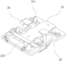
FIG. 2 is a block diagram of a cell fixture according to an embodiment of the present invention;
FIG. 3 is a block diagram of a clamping assembly according to an embodiment of the present invention;
FIG. 4 is a block diagram of an open clamp assembly according to an embodiment of the present invention;
FIG. 5 is a block diagram of a rubberizing mechanism according to an embodiment of the invention;
FIG. 6 is a block diagram of a glue pulling mechanism according to an embodiment of the invention;
FIG. 7 is a block diagram of a dicing mechanism according to an embodiment of the invention;
FIG. 8 is a block diagram of a rubberizing robot according to an embodiment of the invention;
FIG. 9 is an enlarged schematic view at A in FIG. 8;
FIG. 10 is a block diagram of a bending mechanism according to an embodiment of the present invention;
FIG. 11 is a front view of a bending mechanism according to an embodiment of the present invention;
FIG. 12 is an enlarged schematic view at B in FIG. 11;
FIG. 13 is a block diagram of an embodiment of the invention;
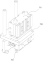
FIG. 14 is a block diagram of a loading positioning mechanism according to an embodiment of the present invention;
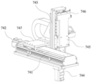
FIG. 15 is a block diagram of a snap-fit robot according to an embodiment of the present invention;
FIG. 16 is a block diagram of a snap-fit assist positioning mechanism according to an embodiment of the present invention.
Detailed Description
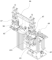
As shown in fig. 1-16, an automatic rubberizing, bending and buckling retainer device for a power battery comprises a rotary table 10, wherein a plurality of sets of battery core clamps 20 for fixing battery cores are arranged at the edge of the rotary table 10, and a battery core feeding unit, a negative electrode tab rubberizing unit 40, a positive electrode tab rubberizing unit 41, a rubberizing failure detection unit 50, a tab bending unit, a buckling retainer unit 70, a buckling retainer unit 71 and a battery core blanking unit are sequentially arranged along the circumference of the rotary table 10; the battery cell feeding unit is provided with a battery cell feeding pull belt 30 and a battery cell feeding manipulator 31 for transferring the battery cells on the battery cell feeding pull belt 30 to the battery cell clamp 20 of the turntable 10; the negative electrode tab rubberizing unit 40 and the positive electrode tab rubberizing unit 41 are respectively provided with rubberizing mechanisms, the rubberizing mechanisms comprise rubberizing mechanisms for rubberizing adhesive tapes on the upper surfaces of the battery cell tabs and rubberizing mechanisms for rubberizing adhesive tapes on the lower surfaces of the battery cell tabs, and the rubberizing mechanisms are respectively symmetrically arranged on the upper side and the lower side of the to-be-rubberized tab; the poor rubberizing detection unit 50 is provided with a rubberizing detection system for detecting whether the tab rubberizes or not; the tab bending unit is provided with a bending mechanism 60 for bending the tab by a certain angle and a bending material taking manipulator 61 for transferring the battery core on the turntable 10 to the bending mechanism 60; the retainer feeding mechanism and the buckling mechanism are respectively arranged on the retainer buckling unit 70 and the retainer buckling unit 71, and the retainer feeding mechanism comprises a feeding vibration disc 75; the battery cell blanking unit is provided with a battery cell blanking pull belt 80, a NG buffer pull belt 81 and a battery cell blanking manipulator 82 for transferring the battery cell autorotation disc 10 to the battery cell blanking pull belt 80 or the NG buffer pull belt 81.
As shown in fig. 2-4, the battery core fixture 20 includes a battery core tray 21 and a clamping assembly for fixing the battery core on the battery core tray 21, the battery core tray 21 is provided with a positioning limiting plate 211 for facilitating the placement of the battery core and a cover plate positioning seat 212 for positioning a battery core cover plate, and the clamping assembly includes two battery core clamping blocks 22 which can be opened and closed relatively, a clamping block mounting seat 24 for mounting the battery core clamping blocks 22 and a first reset mechanism for promoting the two battery core clamping blocks 22 to always have a clamping trend.
The cell clamping blocks 22 are provided with vertical supporting arms 222, cell pressing plates 221 transversely extending from the upper ends of the supporting arms 222 and rocker arms 223 obliquely extending from the lower ends of the supporting arms 222, the two cell clamping blocks 22 are symmetrically arranged on the left side and the right side of the cell tray 21 respectively, the cell pressing plates 221 are located above the cell tray 21, and the lower ends of the two rocker arms 223 are connected with clamping block mounting seats 24 located below the cell tray 21 in a rotating mode respectively. The battery cell tray 21's below is fixed to be equipped with and is used for the direction bearing frame 23 that struts two battery cell clamp splice 22, the both ends of direction bearing frame 23 are equipped with the guide bearing 231 that rolls contact with the medial surface of rocking arm 223 of both sides respectively, fixed being equipped with the guide bar 25 that stretches out downwards on the direction bearing frame 23, be equipped with on the clamp splice mount pad 24 with the guide sleeve 241 of guide bar 25 adaptation, clamp splice mount pad 24 overlaps in guide bar 25 outside movable mounting on guide bar 25 through guide sleeve 241, the lower extreme of guide bar 25 is equipped with the spacing collar 251 that prevents clamp splice mount pad 24 and drop out downwards, the below of battery cell tray 21 still is equipped with the second canceling release mechanical system that makes battery cell clamp plate 221 have the trend of pressing in electric core upper surface all the time, second canceling mechanical system is a compression spring 27, compression spring 27 locates between guide bearing frame 23 and the clamp splice mount pad 24. In the present invention, the first restoring mechanism is two tension springs 26, a hanging hole 232 for installing the tension springs 26 is provided on the side surface of the guide bearing seat 23, a pin 224 for installing the tension springs 26 is provided on the side surface of the rocker arm 223, and during assembly, one end of the tension springs 26 is connected with the hanging hole 232 on the guide bearing seat 23, and the other end is connected with the pin 224 on the rocker arm 223.
The cell clamp 20 further comprises an opening clamp assembly for opening the two cell clamp blocks 22, the opening clamp assembly comprises an opening clamp pushing plate 291 and an opening clamp cylinder 29 for pushing the opening clamp pushing plate 291 to move up and down, the opening clamp cylinder 29 is mounted on the opening clamp bracket 28, the opening clamp bracket 28 is provided with an opening clamp guide rail 281 which is vertically arranged, and the opening clamp pushing plate 291 is arranged on the opening clamp guide rail 281 and can be driven by the opening clamp cylinder 29 to move up and down along the opening clamp guide rail 281. In operation, the clamp opening push plate 291 abuts against the lower surface of the clamp block mounting seat 24, the clamp opening cylinder 29 drives the clamp block mounting seat 24 to push upwards, the pressure spring 27 is compressed, and when the inner side surface of the rocker arms 223 is in contact with the guide bearing 231, the guide bearing 231 pushes the two rocker arms 223 outwards to enable the part of the cell clamp block 22 above the guide bearing 231 to be opened.
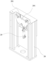
As shown in fig. 5, the rubberizing mechanism comprises a rubberizing module 42, a rubberizing mechanism 43 for pulling out the adhesive tape on the rubberizing module 42, a rubberizing mechanism 44 for cutting off the adhesive tape pulled out by the rubberizing mechanism 43, and a rubberizing manipulator 45 for rubberizing the cut adhesive tape on the upper surface of the battery lug; the adhesive applying and removing mechanism comprises a lower adhesive replacing module 421, a lower adhesive pulling mechanism 431 for pulling out the adhesive tape on the lower adhesive replacing module 421, a lower adhesive cutting mechanism 441 for cutting off the adhesive tape pulled out by the lower adhesive pulling mechanism 431, and a lower adhesive applying manipulator 451 for applying the cut adhesive tape to the lower surface of the tab.
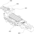
As shown in fig. 6, the glue lifting mechanism 43 and the glue lowering mechanism 431 each include a glue lifting bracket 432, a glue lifting slide 433 and a glue lifting clamp finger 434, wherein the glue lifting slide 433 is movably disposed on the glue lifting bracket 432 and can be driven to slide left and right by a glue lifting motor 435 fixedly disposed on the glue lifting bracket 432, and the glue lifting clamp finger 434 is disposed on the glue lifting slide 433 and can be driven to open and close by a clamp finger cylinder 436 fixedly disposed on the glue lifting slide 433.
As shown in fig. 7, the upper and lower glue cutting mechanisms 44 and 441 each include a cutter cylinder block 442, an upper cutter 447, an upper cutter block 445, an upper cutter cylinder 443, an upper cutter spring pressing plate 4451, a lower cutter 448, a lower cutter block 446, a lower cutter spring pressing plate 4461, and a lower cutter cylinder 444, wherein the upper cutter cylinder 443 and the lower cutter cylinder 444 are fixedly mounted on the cutter cylinder block 442, the upper cutter block 445 is connected with the upper cutter cylinder 443 and can be driven to move up and down by the upper cutter cylinder 443, the lower cutter block 446 is connected with the lower cutter cylinder 444 and can be driven to move up and down by the lower cutter cylinder 444, and the upper cutter 447 and the lower cutter 448 are mounted on the upper cutter block 445 and the lower cutter block 446, respectively, and the opposite surfaces of the upper cutter 447 and the lower cutter 448 are bonded to each other. The upper cutter spring pressing plate 4451 is fixedly arranged on the outer side of the upper cutter seat 445, a guide rod (not shown) extending to the inner side of the upper cutter seat 445 is arranged on the upper cutter spring pressing plate 4451, the upper cutter 447 is movably arranged on the guide rod through a guide sleeve (not shown), a first pushing spring (not shown) which enables the upper cutter 447 to always have a trend of propping against the lower cutter 448 is arranged on the guide rod, the lower cutter spring pressing plate 4461 is fixedly arranged on the outer side of the lower cutter seat 446, the guide rod extending to the inner side of the lower cutter seat 446 is arranged on the lower cutter spring pressing plate 4461, the lower cutter 448 is movably arranged on the guide rod through the guide sleeve, and a second pushing spring (not shown) which enables the lower cutter 448 to always have a trend of propping against the upper cutter 447 is arranged on the guide rod, so that the upper cutter 447 and the lower cutter 448 can be tightly attached together through the action of the first pushing spring and the second pushing spring, and meanwhile the lower cutter 448 can relatively slide. In order to ensure that the cutter works accurately, the two sides of the cutter cylinder seat 442 are also respectively provided with an upper cutter limiting seat 4453 and a lower cutter limiting seat 4462, the upper cutter limiting seat 4453 is positioned below the upper cutter seat 445, and the lower cutter limiting seat 4462 is positioned below the lower cutter seat 446. In order to facilitate the adjustment of the lower cutter stroke, an upper cutter stroke adjustment screw 4452 and a lower cutter stroke adjustment screw 4441 are also included. In order to ensure the accuracy and consistency of the cutting, the upper cutter cylinder 443 is a guide rod cylinder, and the lower cutter cylinder 444 is a sliding table cylinder. When the adhesive is pulled, a through hole through which the adhesive tape can pass is formed between the upper cutter 447 and the lower cutter 448, the adhesive pulling clamp finger 434 passes through the through hole to pull the adhesive tape out of the adhesive changing module, when the adhesive is cut, the upper cutter 443 drives the upper cutter 447 to move downwards, the lower cutter 444 drives the lower cutter 448 to move upwards, and the adhesive tape before passing through the upper cutter 447 and the lower cutter 448 is cut off by the cooperation of the upper cutter 447 and the lower cutter 448.
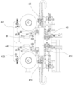
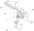
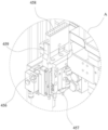
As shown in fig. 8-9, the upper rubberizing manipulator 45 and the lower rubberizing manipulator 451 each comprise a rubberizing mounting seat, a rubberizing Y-axis module 452, a rubberizing Y-axis servo motor 453, a rubberizing Z-axis module 455, a rubberizing Z-axis servo motor 454, a rubberizing X-axis sliding table cylinder 456, a rubberizing sliding table cylinder 457, a rubberizing pressing block 459 and a rubberizing disc 458; the rubberizing Y-axis module 452 is fixedly arranged on a rubberizing mounting seat, and the rubberizing Z-axis module 455 is arranged on the rubberizing Y-axis module 452 and can be driven to move left and right by a rubberizing Y-axis servo motor 453; the rubberizing X-axis sliding table cylinder 456 is arranged on the rubberizing Z-axis servo motor 454 and can be driven by the rubberizing Z-axis servo motor 454 to move up and down; the glue sucking disc 458, the opposite-pasting pressing block 459 and the opposite-pasting sliding table cylinder 457 are arranged on the glue pasting X-axis sliding table cylinder 456 and can be driven by the glue pasting X-axis sliding table cylinder 456 to move back and forth; the number of the pair of pasting pressing blocks 459 is two, and the pair of pasting pressing blocks are respectively arranged on two sides of the glue sucking disc 458 and can be driven by the pair of pasting sliding table cylinders 457 to move up and down. In operation, the upper rubberizing manipulator 45 and the lower rubberizing manipulator 451 are respectively arranged on the upper side and the lower side of the battery cell to be rubberized, and when rubberizing, the two rubberizing discs 458 respectively paste two sections of adhesive tapes on the upper surface and the lower surface of the tab, and the two pairs of rubberizing pressing blocks 459 mutually paste the parts of the two sections of adhesive tapes extending out of the tab.
As shown in fig. 10-12, the bending mechanism 60 includes a bending mounting seat 62, a bending platform 63 disposed on the bending mounting seat 62, and a bending assembly 64 for bending the tab of the battery cell on the bending platform 63, the bending platform 63 is provided with a battery cell clamping plate 631 for fixing the battery cell, the bending assembly 64 includes a bending bracket 641, a left-right displacement sliding table 642 disposed on the bending bracket 641, an up-down displacement sliding table 643 driven by the left-right displacement sliding table 642 to move left and right, and a bending piece 644 driven by the up-down displacement sliding table 643 to move up and down, wherein a bending inclined plane 645 for bending the tab at a certain angle is disposed at the lower end of the bending piece 644; the bending material taking manipulator 61 comprises a rotating shaft 65, a material taking mounting plate 66 arranged at the upper end of the rotating shaft 65, and battery core clamping claws 67 symmetrically arranged at two ends of the material taking mounting plate 66. During operation, the electric core clamping jaw 67 grabs the electric core 90 from the turntable 10, the rotation shaft 65 is driven to rotate by the driving equipment, the electric core 90 is transferred to the bending platform 63, after being fixed by the electric core clamping plate 631, the bending piece 644 is driven to move leftwards by the left-right displacement sliding table 642 and then to move downwards by the up-down displacement sliding table 643, the lug 91 of the electric core 90 is bent by a certain angle under the action of the bending inclined plane 645 at the lower end, and then the bent electric core is returned to the turntable by the bending material taking manipulator 61 and is sent to the next process by the turntable.
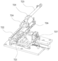
13-16, the buckling mechanism comprises a feeding positioning mechanism 72, a buckling mechanical arm 74 and a buckling auxiliary positioning mechanism 73; the feeding vibration plate 75 is connected with the feeding positioning mechanism 72 through a retainer trough 76, the feeding positioning mechanism 72 is provided with a positioning station 721, a transfer cylinder 723 for pushing the retainer on the retainer trough 76 to the positioning station 721, a transfer slide seat 724 driven to move by the transfer cylinder 723, a lifting slide table cylinder 725 arranged on the transfer slide seat 724, a transfer sucker 726 driven to move up and down by the lifting slide table cylinder 725 and a positioning assembly 727 for positioning the retainer in the positioning station 721 are arranged beside the positioning station 721; the buckling manipulator 74 comprises a buckling Y-axis module 741, a buckling Y-axis motor 742, a buckling Z-axis module 743, a buckling Z-axis motor 744 and a buckling sucker 746 for sucking a retainer in the positioning station 721, wherein the buckling Z-axis module 743 is mounted on the buckling Y-axis module 741 through a left-right displacement slide seat 747 and can be driven by the buckling Y-axis motor 742 to move along the Y-axis, and the buckling sucker 746 is mounted on the buckling Z-axis module 743 through an up-down displacement slide seat 745 and can be driven by the buckling Z-axis motor 744 to move along the Z-axis. The fastening auxiliary positioning mechanism 73 comprises a retainer limiting cylinder 731 and a retainer limiting block 733 which is driven by the retainer limiting cylinder 731 to move up and down, wherein the retainer limiting block 733 is arranged at the lower end of the retainer limiting cylinder 731 through a retainer positioning plate 732. In operation, the holder on the vibration plate is transferred to the lower part of the transferring sucker 726 through the holder trough 76, the transferring sucker 726 is controlled by the lifting sliding table cylinder 725 to absorb the holder, the transferring sliding seat 724 is driven by the transferring cylinder 723 to move, the holder absorbed by the transferring sucker 726 is transferred to the positioning station 721, the positioning component 727 acts to position the holder, and then the buckling mechanical arm 74 absorbs the positioned holder and buckles the holder on the battery cell 90.
The working flow of the invention is as follows:
the battery cell is conveyed to the side of the rotary table 10 by the battery cell feeding pull belt 30, the battery cell feeding manipulator 31 takes the battery cell to the battery cell clamp 20 of the rotary table 10, the battery cell rotates to a rubberizing station along with the rotary table 10, the cathode tab rubberizing unit 40 and the anode tab rubberizing unit 41 are respectively rubberized and lower at the tab welding positions of the cathode and the anode, the battery cell rotates to the rubberizing defect detection unit 50 along with the rotary table 10, the rubberizing detection system detects whether the rubberizing effect is good or bad, the battery cell rotates to the tab bending unit along with the rotary table 10, the bending material manipulator 61 takes the bending mechanism 60 to bend the tab at a certain angle, then the battery cell is conveyed to the rotary table 10 by the bending material manipulator 61, the battery cell rotates to a buckling retainer station along with the rotary table 10, the buckling retainer unit 70 and the buckling retainer unit 71 are respectively buckled and the upper retainer, the battery cell rotates to the blanking unit, the battery cell blanking manipulator 82 grabs the NG cache pull belt 81, and the battery cell grabs the good battery cell to the battery cell blanking pull belt 80, and the battery cell is conveyed to the lower wire pull belt 80.
The foregoing description is only a preferred embodiment of the present invention, and is not intended to limit the present invention, so any modifications, equivalents, improvements, etc. of the above embodiments according to the present invention are still within the scope of the present invention.
Claims (10)
1. The utility model provides an automatic rubberizing of power battery, buckle holder device, its characterized in that: the battery cell feeding device comprises a rotary table, wherein a plurality of battery cell clamps used for fixing battery cells are arranged at the edge of the rotary table, and a battery cell feeding unit, a negative electrode tab rubberizing unit, a positive electrode tab rubberizing unit, a rubberizing defect detecting unit, a tab bending unit, a buckling lower retainer unit, a buckling upper retainer unit and a battery cell blanking unit are sequentially arranged along the circumference of the rotary table;
the battery cell feeding unit is provided with a battery cell feeding pull belt and a battery cell feeding manipulator used for transferring the battery cells on the battery cell feeding pull belt to a battery cell clamp of the turntable; the negative electrode tab rubberizing unit and the positive electrode tab rubberizing unit are respectively provided with rubberizing mechanisms, the rubberizing mechanisms comprise rubberizing mechanisms for rubberizing adhesive tapes on the upper surfaces of the battery cell tabs and rubberizing mechanisms for rubberizing adhesive tapes on the lower surfaces of the battery cell tabs, and the rubberizing mechanisms are respectively symmetrically arranged on the upper side and the lower side of the to-be-rubberized tab; the poor rubberizing detection unit is provided with a rubberizing detection system for detecting whether the tab rubberizes or not; the tab bending unit is provided with a bending mechanism for bending the tab by a certain angle and a bending material taking manipulator for transferring the battery core on the turntable to the bending mechanism; the retainer feeding mechanism and the buckling mechanism are used for buckling the retainer conveyed by the retainer feeding mechanism to the battery cell; the battery cell blanking unit is provided with a battery cell blanking pull belt, an NG buffer pull belt and a battery cell blanking manipulator for transferring the battery cell autorotation disc to the battery cell blanking pull belt or the NG buffer pull belt.
2. The automatic power cell rubberizing, bending and buckling retainer apparatus of claim 1, wherein: the battery cell clamp comprises a battery cell tray and a clamping assembly used for fixing a battery cell on the battery cell tray, wherein the clamping assembly comprises two battery cell clamping blocks capable of opening and closing relatively, a clamping block mounting seat used for mounting the battery cell clamping blocks and a first reset mechanism used for enabling the two battery cell clamping blocks to always have a clamping trend, the battery cell clamping blocks are provided with vertical supporting arms, a battery cell pressing plate transversely extending from the upper ends of the supporting arms and rocker arms obliquely extending from the lower ends of the supporting arms, the two battery cell clamping blocks are symmetrically arranged on the left side and the right side of the battery cell tray respectively, the battery cell pressing plate is located above the battery cell tray, the lower ends of the two rocker arms are respectively connected with the clamping block mounting seat located below the battery cell tray in a rotating mode, guide bearing seats used for expanding the two battery cell clamping blocks are fixedly arranged below the battery cell tray, two ends of the guide bearing seats are respectively provided with guide bearings which are in rolling contact with the inner side faces of the rocker arms on the two sides, and a second reset mechanism used for enabling the battery cell pressing plate to always have a trend on the upper surface of the battery cell.
3. The automatic power cell rubberizing, bending and buckling retainer apparatus of claim 2, wherein: the first reset mechanism is two tension springs, a hanging hole for installing the tension springs is formed in the side face of the guide bearing seat, a pin shaft for installing the tension springs is arranged on the side face of the rocker arm, one end of the tension springs is connected with the hanging hole on the guide bearing seat during assembly, and the other end of the tension springs is connected with the pin shaft on the rocker arm.
4. The automatic power cell rubberizing, bending and buckling retainer apparatus of claim 2, wherein: the guide bearing seat is fixedly provided with a guide rod which extends downwards, the clamping block mounting seat is provided with a guide sleeve which is matched with the guide rod, the clamping block mounting seat is movably mounted on the guide rod outside the guide rod through the guide sleeve, the lower end of the guide rod is provided with a limiting ring which prevents the clamping block mounting seat from falling downwards, the second reset mechanism is a pressure spring, and the pressure spring is arranged between the guide bearing seat and the clamping block mounting seat.
5. The automatic power cell rubberizing, bending and buckling retainer apparatus of claim 1, wherein: the rubberizing mechanism comprises a rubberizing module, a rubberizing mechanism for pulling out the adhesive tape on the rubberizing module, a rubberizing mechanism for cutting off the adhesive tape pulled out by the rubberizing mechanism, and a rubberizing manipulator for sticking the cut adhesive tape to the upper surface of the battery cell tab; the adhesive sticking and discharging mechanism comprises a lower adhesive changing module, a lower adhesive pulling mechanism for pulling out the adhesive tape on the lower adhesive changing module, a lower adhesive cutting mechanism for cutting off the adhesive tape pulled out by the lower adhesive pulling mechanism, and a lower adhesive sticking manipulator for sticking the cut adhesive tape to the lower surface of the tab.
6. The automatic power cell rubberizing, bending and button retainer apparatus of claim 5, wherein: the upper glue pulling mechanism and the lower glue pulling mechanism comprise a glue pulling support, a glue pulling sliding seat and glue pulling clamping fingers, the glue pulling sliding seat is movably arranged on the glue pulling support and can be driven to slide left and right by a glue pulling motor fixedly arranged on the glue pulling support, and the glue pulling clamping fingers are arranged on the glue pulling sliding seat and can be driven to open and close by a clamping finger cylinder fixedly arranged on the glue pulling sliding seat.
7. The automatic power cell rubberizing, bending and button retainer apparatus of claim 5, wherein: the upper rubberizing manipulator and the lower rubberizing manipulator comprise rubberizing installation seats, rubberizing Y-axis modules, rubberizing Y-axis servo motors, rubberizing Z-axis servo motors, rubberizing X-axis sliding table cylinders, opposite-to-sticking pressing blocks and rubberizing discs, wherein the rubberizing Y-axis modules, the rubberizing Y-axis servo motors, the rubberizing Z-axis servo motors, the rubberizing X-axis sliding table cylinders, the opposite-to-sticking pressing blocks and the rubberizing discs are arranged on the rubberizing installation seats; the rubberizing Y-axis module is fixedly arranged on the rubberizing mounting seat, and the rubberizing Z-axis module is arranged on the rubberizing Y-axis module and can be driven by a rubberizing Y-axis servo motor to move left and right; the rubberizing X-axis sliding table cylinder is arranged on the rubberizing Z-axis servo motor and can be driven by the rubberizing Z-axis servo motor to move up and down; the adhesive suction disc, the opposite-pasting pressing block and the opposite-pasting sliding table cylinder are arranged on the adhesive pasting X-axis sliding table cylinder and can be driven by the adhesive pasting X-axis sliding table cylinder to move back and forth; the number of the opposite-sticking pressing blocks is two, and the opposite-sticking pressing blocks are respectively arranged on the front side and the rear side of the glue sucking disc and can be driven by the opposite-sticking sliding table cylinder to move up and down.
8. The automatic power cell rubberizing, bending and button retainer apparatus of claim 5, wherein: the upper rubber cutting mechanism and the lower rubber cutting mechanism comprise a cutter cylinder seat, an upper cutter seat, an upper cutter cylinder, a lower cutter seat and a lower cutter cylinder, wherein the upper cutter cylinder and the lower cutter cylinder are fixedly arranged on the cutter cylinder seat, the upper cutter seat is connected with the upper cutter cylinder and can be driven to move up and down by the upper cutter cylinder, the lower cutter seat is connected with the lower cutter cylinder and can be driven to move up and down by the lower cutter cylinder, and the upper cutter and the lower cutter are respectively arranged on the upper cutter seat and the lower cutter seat, and the opposite surfaces of the upper cutter and the lower cutter are mutually attached.
9. The automatic power cell rubberizing, bending and buckling retainer apparatus of claim 1, wherein: the bending mechanism comprises a bending mounting seat, a bending platform arranged on the bending mounting seat and a bending assembly used for bending the lugs of the battery cells on the bending platform, wherein a battery cell clamping plate used for fixing the battery cells is arranged on the bending platform; the bending and material taking manipulator comprises a rotating shaft, a material taking mounting plate arranged at the upper end of the rotating shaft, and battery core clamping jaws symmetrically arranged at two ends of the material taking mounting plate.
10. The automatic power cell rubberizing, bending and buckling retainer apparatus of claim 1, wherein: the retainer feeding mechanism comprises a feeding vibration disc, and the buckling mechanism comprises a feeding positioning mechanism, a buckling mechanical arm and a buckling auxiliary positioning mechanism; the feeding vibration disc is connected with a feeding positioning mechanism through a retainer trough, the feeding positioning mechanism is provided with a positioning station, and a transfer cylinder for pushing a retainer on the retainer trough to the positioning station, a transfer sliding seat driven to move by the transfer cylinder, a lifting sliding table cylinder arranged on the transfer sliding seat, a transfer sucking disc driven to move up and down by the lifting sliding table cylinder and a positioning assembly for positioning the retainer in the positioning station are arranged beside the positioning station; the buckling manipulator comprises a buckling Y-axis module, a buckling Y-axis motor, a buckling Z-axis module, a buckling Z-axis motor and a buckling sucker for sucking a retainer in a positioning station, wherein the buckling Z-axis module is arranged on the buckling Y-axis module and can be driven by the buckling Y-axis motor to move along the Y-axis, the buckling sucker is arranged on the buckling Z-axis module and can be driven by the buckling Z-axis motor to move along the Z-axis, and the buckling auxiliary positioning mechanism comprises a retainer limiting cylinder and a retainer limiting block which is driven by the retainer limiting cylinder to move up and down.
Applications Claiming Priority (2)
| Application Number | Priority Date | Filing Date | Title |
|---|---|---|---|
| CN2016111450881 | 2016-12-13 | ||
| CN201611145088 | 2016-12-13 |
Publications (2)
| Publication Number | Publication Date |
|---|---|
| CN106816624A CN106816624A (en) | 2017-06-09 |
| CN106816624B true CN106816624B (en) | 2023-05-12 |
Family
ID=59115078
Family Applications (1)
| Application Number | Title | Priority Date | Filing Date |
|---|---|---|---|
| CN201710157656.8A Active CN106816624B (en) | 2016-12-13 | 2017-03-16 | Automatic rubberizing, bending and buckling retainer device for power battery |
Country Status (1)
| Country | Link |
|---|---|
| CN (1) | CN106816624B (en) |
Families Citing this family (25)
| Publication number | Priority date | Publication date | Assignee | Title |
|---|---|---|---|---|
| CN107394225B (en) * | 2017-07-17 | 2020-03-27 | 深圳市卓誉自动化科技有限公司 | Power battery cell binding mechanism |
| CN107482244B (en) * | 2017-08-07 | 2023-08-18 | 东莞市优睿特自动化设备有限公司 | Full-automatic shell machine of going into of electricity core |
| CN107310143B (en) * | 2017-08-22 | 2023-05-23 | 惠州市德赛自动化技术有限公司 | Battery side rubber coating machine |
| CN107634269B (en) * | 2017-09-15 | 2023-11-24 | 东莞市中造新材料科技有限公司 | Tab rubberizing machine |
| CN107511612B (en) * | 2017-09-15 | 2019-06-28 | 安徽机电职业技术学院 | A kind of feeding mechanism of battery core spot welding device |
| CN107768725B (en) * | 2017-09-28 | 2024-02-20 | 海目星(江门)激光智能装备有限公司 | Battery cell retainer mounting equipment |
| CN107597897A (en) * | 2017-10-30 | 2018-01-19 | 苏州哈工众志自动化科技有限公司 | The automatic bending machine of valve block |
| CN108123092B (en) * | 2017-12-21 | 2020-08-28 | 宁波捷傲创益新材料有限公司 | Utmost point ear rubber coating device |
| CN107994263B (en) * | 2018-01-15 | 2024-03-29 | 惠州市恒泰科技股份有限公司 | Battery tab rubberizing folding all-in-one |
| CN110937449A (en) * | 2018-09-25 | 2020-03-31 | 张家港百舸光电科技有限公司 | Lithium battery tab bending and film pasting device |
| CN109309259A (en) * | 2018-11-12 | 2019-02-05 | 东莞市爱康电子科技有限公司 | A kind of automatic rubberizing folding tab equipment |
| CN109378527A (en) * | 2018-11-30 | 2019-02-22 | 珠海市嘉德电能科技有限公司 | A kind of battery core adhesive tape rubberizing mechanism |
| CN109301347B (en) * | 2018-11-30 | 2024-01-26 | 珠海市嘉德电能科技有限公司 | Battery cell glue sealing equipment |
| CN109780023B (en) * | 2018-12-25 | 2021-01-29 | 广东天机工业智能系统有限公司 | Laminating device |
| CN109921096B (en) * | 2019-03-07 | 2024-02-23 | 广东鸿宝科技有限公司 | Electrolyte liquid-retaining amount closed-loop control method of battery sealing machine |
| CN110010951A (en) * | 2019-03-28 | 2019-07-12 | 深圳市倍斯特科技股份有限公司 | Double sided stick adhesive equipment for battery core rubberizing |
| CN110048152A (en) * | 2019-05-06 | 2019-07-23 | 广东东博自动化设备有限公司 | A kind of full-automatic rubberizing production line of battery |
| CN110492047B (en) * | 2019-09-20 | 2024-04-09 | 广东拓斯达科技股份有限公司 | Bending rubberizing machine and battery production line |
| CN112290100B (en) * | 2020-10-29 | 2022-03-29 | 广东技术师范大学 | Battery cell rubberizing device |
| CN112635921B (en) * | 2020-12-22 | 2022-11-25 | 上海骄成超声波技术股份有限公司 | A rubberizing mechanism for square battery utmost point ear |
| CN114094159B (en) * | 2021-11-10 | 2024-04-12 | 东莞朗景智能科技有限公司 | Battery tab encapsulation paper equipment |
| CN114361554B (en) * | 2021-12-31 | 2024-04-05 | 无锡骄成智能科技有限公司 | Forward and backward rubberizing device and rubberizing method for battery cell lugs and related production line |
| CN114335670A (en) * | 2021-12-31 | 2022-04-12 | 无锡骄成智能科技有限公司 | Battery cell automatic production line process circulation system and method |
| CN115425271B (en) * | 2022-09-15 | 2024-02-02 | 武汉逸飞激光股份有限公司 | Square cell protection frame assembly device and assembly method |
| CN116230974B (en) * | 2023-02-18 | 2023-11-10 | 深圳市誉辰智能装备股份有限公司 | Battery core combining and packaging machine |
Citations (6)
| Publication number | Priority date | Publication date | Assignee | Title |
|---|---|---|---|---|
| JP3066179U (en) * | 1999-07-29 | 2000-02-18 | 黄 秋逢 | Automatic taping machine for printed wiring boards |
| WO2012022063A1 (en) * | 2010-08-20 | 2012-02-23 | 深圳市吉阳自动化科技有限公司 | Epicyclic clamp, method and device for assembling power cell |
| CN203644888U (en) * | 2013-11-29 | 2014-06-11 | 东莞市鸿宝锂电科技有限公司 | Tab adhesive tape sticking mechanism |
| CN203644864U (en) * | 2013-11-29 | 2014-06-11 | 东莞市鸿宝锂电科技有限公司 | Automatic welding, cutting and adhesive tape sticking device for tab |
| CN205177950U (en) * | 2015-11-19 | 2016-04-20 | 广东鸿宝科技有限公司 | Automatic rubberizing of power battery and bales catch holder device |
| CN206619657U (en) * | 2016-12-13 | 2017-11-07 | 广东鸿宝科技有限公司 | Electrokinetic cell automatic rubberizing, bending, button retainer device |
-
2017
- 2017-03-16 CN CN201710157656.8A patent/CN106816624B/en active Active
Patent Citations (6)
| Publication number | Priority date | Publication date | Assignee | Title |
|---|---|---|---|---|
| JP3066179U (en) * | 1999-07-29 | 2000-02-18 | 黄 秋逢 | Automatic taping machine for printed wiring boards |
| WO2012022063A1 (en) * | 2010-08-20 | 2012-02-23 | 深圳市吉阳自动化科技有限公司 | Epicyclic clamp, method and device for assembling power cell |
| CN203644888U (en) * | 2013-11-29 | 2014-06-11 | 东莞市鸿宝锂电科技有限公司 | Tab adhesive tape sticking mechanism |
| CN203644864U (en) * | 2013-11-29 | 2014-06-11 | 东莞市鸿宝锂电科技有限公司 | Automatic welding, cutting and adhesive tape sticking device for tab |
| CN205177950U (en) * | 2015-11-19 | 2016-04-20 | 广东鸿宝科技有限公司 | Automatic rubberizing of power battery and bales catch holder device |
| CN206619657U (en) * | 2016-12-13 | 2017-11-07 | 广东鸿宝科技有限公司 | Electrokinetic cell automatic rubberizing, bending, button retainer device |
Also Published As
| Publication number | Publication date |
|---|---|
| CN106816624A (en) | 2017-06-09 |
Similar Documents
| Publication | Publication Date | Title |
|---|---|---|
| CN106816624B (en) | Automatic rubberizing, bending and buckling retainer device for power battery | |
| CN107046145B (en) | Automatic core-closing rubberizing machine for power battery | |
| CN206619657U (en) | Electrokinetic cell automatic rubberizing, bending, button retainer device | |
| CN107527753B (en) | Capacitor glue wrapping paper machine | |
| CN210849131U (en) | Carbon brush assembling equipment | |
| CN112259924A (en) | Lithium battery tab wrapping and gluing machine and gluing method | |
| CN106384836B (en) | Automatic rubberizing and automatic buckle holder device of power battery | |
| CN113500790B (en) | Tool for automatically bonding adhesive tape and using method thereof | |
| CN108247343B (en) | Automatic assembly machine for dial potentiometer | |
| CN208361514U (en) | A kind of braid capacitor adhesive tape adhering machine | |
| CN214336757U (en) | Battery cell tab and cover plate welding system | |
| CN116759377B (en) | Edge sealing device capable of self-adaptively clamping for solar double-glass production | |
| CN109638307A (en) | A kind of lithium battery electric core automatic encapsulation device | |
| CN112490486A (en) | Battery cell tab and cover plate welding system | |
| CN110814741B (en) | New energy battery assembling equipment with protection structure and working method thereof | |
| CN112968206A (en) | Battery production line | |
| CN219093398U (en) | Single silver point riveting press | |
| CN210064698U (en) | FPC rubberizing divides strip equipment | |
| CN115376985B (en) | Compatible high dual glass assembly tears sticky tape module and tears sealing-tape machine | |
| CN111081610A (en) | Device for realizing automatic black glue feeding | |
| CN216970134U (en) | Full-automatic sticking film machine | |
| CN214326647U (en) | Automatic disk changing device for photovoltaic solder strip production | |
| CN106654342B (en) | Full-automatic patch silicagel pad machine | |
| CN214298569U (en) | Rubberizing device and electric core utmost point ear welding system | |
| CN203592758U (en) | Side face covering machine of packaging box |
Legal Events
| Date | Code | Title | Description |
|---|---|---|---|
| PB01 | Publication | ||
| PB01 | Publication | ||
| SE01 | Entry into force of request for substantive examination | ||
| SE01 | Entry into force of request for substantive examination | ||
| GR01 | Patent grant | ||
| GR01 | Patent grant |