CN216970134U - Full-automatic sticking film machine - Google Patents
Full-automatic sticking film machine Download PDFInfo
- Publication number
- CN216970134U CN216970134U CN202123274216.1U CN202123274216U CN216970134U CN 216970134 U CN216970134 U CN 216970134U CN 202123274216 U CN202123274216 U CN 202123274216U CN 216970134 U CN216970134 U CN 216970134U
- Authority
- CN
- China
- Prior art keywords
- seat
- film
- feeding mechanism
- support
- workpiece
- Prior art date
- Legal status (The legal status is an assumption and is not a legal conclusion. Google has not performed a legal analysis and makes no representation as to the accuracy of the status listed.)
- Active
Links
Images


Abstract
The utility model discloses a full-automatic film sticking machine which comprises a machine case, a workpiece fixture, a rotary disc type feeding mechanism, a workpiece conveying mechanism, a material sucking and feeding mechanism, a film material feeding mechanism, a film sticking mechanism for sucking a film material and sticking the film material to a workpiece and a material sucking and discharging mechanism for sucking the film-stuck workpiece and sending the workpiece out. The automatic film pasting machine can realize automatic film pasting operation of the shell of the Bluetooth headset, has high automation degree, replaces manual operation, has high production efficiency and high film pasting precision, can ensure production quality, and can meet the large-scale production requirements of enterprises.
Description
Technical Field
The utility model relates to the technical field of automation equipment, in particular to a full-automatic film sticking machine.
Background
In bluetooth headset's assembly line, need to paste the protection film toward the surface of bluetooth headset shell, however, all adopt the staff pad pasting in the current production line, artifical pad pasting is comparatively troublesome, wastes time and energy, and the pad pasting precision is low, and production quality is uneven, and production efficiency is low, is unfavorable for production.
SUMMERY OF THE UTILITY MODEL
The utility model aims to overcome the defects in the prior art and provides a full-automatic film sticking machine.
In order to achieve the purpose, the utility model provides a full-automatic film sticking machine, which comprises a machine box, a workpiece fixture, a rotary disc type feeding mechanism, a workpiece conveying mechanism for conveying workpieces to a material sucking station of the material sucking and feeding mechanism, a material sucking and feeding mechanism for sucking the workpieces and transferring the workpieces to the workpiece fixture, a film material feeding mechanism for film material feeding, a film sticking mechanism for sucking the film materials and sticking the film materials to the workpieces, and a material sucking and discharging mechanism for sucking the film-stuck workpieces and discharging the workpieces, wherein the rotary disc type feeding mechanism, the workpiece conveying mechanism, the material sucking and feeding mechanism, the film material feeding mechanism and the material sucking and discharging mechanism are all arranged at the top of the machine box, the workpiece fixture is provided with a plurality of rotary discs which are uniformly arranged at the edge of the top of the rotary disc type feeding mechanism, and the workpiece conveying mechanism, the film material feeding mechanism and the material sucking and discharging mechanism are sequentially arranged at the periphery of the rotary disc type feeding mechanism along the feeding direction of the rotary disc type feeding mechanism, inhale material feed mechanism and be located between carousel formula feeding mechanism and the work piece conveying mechanism, pad pasting mechanism installs the ejection of compact position at membrane material feeding mechanism and is located carousel formula feeding mechanism's pad pasting station top.
As a preferred embodiment, the workpiece conveying mechanism includes a first moving module, a workpiece carrier, a carrier mounting seat and a first rotating motor, the first moving module is mounted on the chassis through a mounting base plate, the carrier mounting seat is mounted on the first moving module, the workpiece carrier is rotatably mounted on the carrier mounting seat, the first rotating motor is mounted on one side of the carrier mounting seat through a motor plate, and an output shaft of the first rotating motor is in transmission connection with the workpiece carrier through a first transmission assembly so as to drive the workpiece carrier to rotate.
As a preferred embodiment, the material sucking and feeding mechanism comprises a second moving module, a first translating seat, a first lifting cylinder and a first material sucking head, the second moving module is horizontally mounted on the first support, the first translating seat is mounted on the second moving module, the first lifting cylinder is mounted on the first translating seat in a downward direction, and the first material sucking head is connected with an output shaft of the first lifting cylinder through a first mounting block.
In a preferred embodiment, the rotating disc type feeding mechanism comprises a second rotating motor and a cam divider, the cam divider is mounted at the top of the chassis, the second rotating motor is mounted in the chassis and connected with the input part of the cam divider through a second transmission assembly, and the rotating disc is mounted at the output part of the cam divider and is positioned above the cam divider.
As a preferred embodiment, the film material feeding mechanism comprises a support, a material tray discharging frame, a third rotating motor, a feeding guide roller, a material pressing plate, a material pressing cylinder, a guide groove seat, a second translation seat, a translation cylinder, a stripping knife, a material receiving guide roller, a material receiving clamping roller, a fourth rotating motor, a waste belt winding shaft and a fifth rotating motor, wherein the material tray discharging frame is rotatably arranged at the upper end of the support, the third rotating motor is in transmission connection with the material tray discharging frame to drive the material tray discharging frame to rotate, the guide groove seat is arranged at the middle position of the front surface of the support, the feeding guide rollers are provided with a plurality of rollers and are respectively arranged at the front surface of the support, the material pressing cylinder is longitudinally arranged at the front surface of the support and is positioned above the material feeding end of the material pressing cylinder, the material pressing plate is arranged on an output shaft of the material pressing cylinder and is positioned between the material feeding end of the guide groove seat and the material pressing cylinder, the second translation seat is installed on the front face of the support in a translation mode and located on the side edge of the guide groove seat, the translation cylinder is installed on the back of the support and connected with the second translation seat to drive the translation cylinder to translate, the stripping knife is horizontally installed on the second translation seat and located below the film sticking mechanism, an inclined plane which inclines towards the direction close to one end of the guide groove seat from top to bottom is arranged at the bottom of one end, far away from the guide groove seat, of the stripping knife, the two receiving guide rollers are arranged, one receiving guide roller is installed on the front face of the support and located below the stripping knife, the other receiving guide roller is installed on the second translation seat and located at one end, close to the guide groove seat, of the stripping knife, the two receiving clamping rollers are arranged up and down, the two receiving clamping rollers are rotatably installed on a guide roller frame arranged at the lower end of the guide groove seat, the fourth rotating motor is installed on the support and is in transmission connection with the receiving clamping rollers through a third transmission assembly, the waste tape winding shaft is rotatably arranged on the front surface of the support, and the fifth rotating motor is arranged on the back of the support and is in transmission connection with the waste tape winding shaft.
In a preferred embodiment, the front surface of the second translation seat is provided with a strip detection optical fiber positioned above one side of the stripping knife.
As a preferred embodiment, the film sticking mechanism comprises a film suction head, a film suction head mounting seat and a second lifting cylinder, the second lifting cylinder is mounted at the top of the motor mounting seat downwards, the film suction head mounting seat is mounted on the motor mounting seat in a vertically sliding manner and is located below the second lifting cylinder, an output shaft of the second lifting cylinder is connected with the top of the film suction head mounting seat, and the film suction head is mounted at the bottom of the film suction head mounting seat.
As a preferred embodiment, the material sucking and discharging mechanism comprises a third moving module, a third moving base, a third lifting cylinder and a second material sucking head, the third moving module is horizontally mounted on the second support, the third moving base is mounted on the third moving module, the third lifting cylinder is mounted on the third moving base in a downward direction, and the second material sucking head is connected with an output shaft of the third lifting cylinder through a second mounting block.
Compared with the prior art, the utility model has the beneficial effects that:
the automatic film pasting machine is simple and novel in structure and reasonable in design, can realize automatic film pasting operation of the shell of the Bluetooth headset, is high in automation degree, replaces manual operation, is high in production efficiency and high in film pasting precision, can guarantee production quality, and can meet the large-scale production requirements of enterprises.
Drawings
In order to more clearly illustrate the embodiments or technical solutions of the present invention, the drawings used in the embodiments or technical solutions in the prior art are briefly introduced below, and it is obvious that the drawings in the following description are some embodiments of the present invention, and it is obvious for those skilled in the art that other drawings can be obtained according to these drawings without creative efforts.
Fig. 1 is a first schematic structural diagram of a full-automatic film sticking machine according to an embodiment of the present invention;
fig. 2 is a schematic structural diagram of a full-automatic film sticking machine according to an embodiment of the present invention;
FIG. 3 is a schematic structural diagram of a material loading portion of a workpiece conveying mechanism of a full-automatic film laminator according to an embodiment of the present invention;
FIG. 4 is a schematic structural diagram of a translation portion of a suction feeding mechanism of a full-automatic film laminator according to an embodiment of the present invention;
fig. 5 is a schematic structural view of a rotating disc type feeding mechanism of a full-automatic film sticking machine according to an embodiment of the present invention;
fig. 6 is a first structural schematic diagram of a film sticking mechanism and a film material feeding mechanism of a full-automatic film sticking machine according to an embodiment of the present invention;
fig. 7 is a second schematic structural diagram of a film sticking mechanism and a film material feeding mechanism of a full-automatic film sticking machine according to an embodiment of the present invention;
FIG. 8 is a schematic back structural view of a film feeding mechanism of a full-automatic film laminator according to an embodiment of the present invention;
fig. 9 is a schematic structural view of a stripping knife of a full-automatic laminator according to an embodiment of the present invention;
fig. 10 is a schematic structural view of a translation portion of a material sucking and discharging mechanism of a full-automatic film sticking machine according to an embodiment of the present invention.
Detailed Description
In order to make the objects, technical solutions and advantages of the embodiments of the present invention clearer, the technical solutions in the embodiments of the present invention will be clearly and completely described below with reference to the drawings in the embodiments of the present invention, and it is obvious that the described embodiments are some, but not all, embodiments of the present invention. All other embodiments, which can be derived by a person skilled in the art from the embodiments given herein without making any creative effort, shall fall within the protection scope of the present invention.
Referring to fig. 1 to 10, an embodiment of the present invention provides a full-automatic film sticking machine, which includes a machine case 1, a workpiece fixture 2, a turntable type feeding mechanism 3, a workpiece conveying mechanism 4 for conveying a workpiece (a bluetooth headset housing) to a material suction station of a material suction feeding mechanism 5, a material suction feeding mechanism 5 for sucking a workpiece and transferring the workpiece to the workpiece fixture 2, a film material feeding mechanism 6 for feeding a film material, a film sticking mechanism 7 for sucking a film material and sticking the film material to the workpiece, and a material suction discharging mechanism 8 for sucking a film-stuck workpiece and discharging the workpiece, and the structures of the respective components and the operating principles thereof will be described below.
The turntable type feeding mechanism 3, the workpiece conveying mechanism 4, the suction material feeding mechanism 5, the film material feeding mechanism 6 and the suction material discharging mechanism 8 are all installed at the top of the case 1, the workpiece conveying mechanism 4, the film material feeding mechanism 6 and the suction material discharging mechanism 8 are sequentially arranged on the periphery of the turntable type feeding mechanism 3 along the feeding direction of the turntable type feeding mechanism 3, and the suction material feeding mechanism 5 is located between the turntable type feeding mechanism 3 and the workpiece conveying mechanism 4.
Preferably, the workpiece conveying mechanism 4 may include a first moving module 41, a workpiece carrier 42, a carrier mounting seat 43 and a first rotating motor 44, the first moving module 41 is mounted on the chassis 1 through a mounting base plate, the carrier mounting seat 43 is mounted on the first moving module 41, the workpiece carrier 42 is rotatably mounted on the carrier mounting seat 43, the first rotating motor 44 is mounted on one side of the carrier mounting seat 43 through a motor plate, and an output shaft of the first rotating motor 44 is in transmission connection with the workpiece carrier 42 through a first transmission assembly (belt + belt pulley + rotating shaft) 45 to drive the workpiece carrier to rotate.
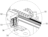
Preferably, the suction feeding mechanism 5 may include a second moving module 51, a first translating base 52, a first elevating cylinder 53 and a first suction head 54, the second moving module 51 is horizontally mounted on a first bracket 55, the first translating base 52 is mounted on the second moving module 51, the first elevating cylinder 53 is mounted downward on the first translating base 52, and the first suction head 54 is connected with an output shaft of the first elevating cylinder 53 through a first mounting block 56.
Specifically, the rotating disc type feeding mechanism 3 may include a rotating disc 31, a second rotating motor and a cam divider 33, the cam divider 33 is installed at the top of the chassis 1, the second rotating motor is installed in the chassis 1 and connected to the input portion of the cam divider 33 through a second transmission assembly (belt + belt pulley) 34, the rotating disc 31 is installed at the output portion of the cam divider 33 and located above the cam divider 33, and the work jigs 2 are provided with a plurality of parts and uniformly arranged at the top edge of the rotating disc 31.
The film material feeding mechanism 6 comprises a support 601, a tray discharging frame 602, a third rotating motor 603, a feeding guide roller 604, a material pressing plate 605, a material pressing cylinder 606, a guide groove seat 607, a second translation seat 608, a translation cylinder 609, a stripping knife 610, a material receiving guide roller 611, a material receiving clamping roller 612, a fourth rotating motor 613, a waste tape winding shaft 614 and a fifth rotating motor 615, wherein the tray discharging frame 602 is rotatably arranged at the upper end of the support 601, the third rotating motor 603 is in transmission connection with the tray discharging frame 602 to drive the third rotating motor to rotate, the guide groove seat 607 is arranged at the middle position of the front surface of the support 601, the feeding guide rollers 604 are provided with a plurality of rollers and are respectively arranged at the front surface of the support 601, the feeding guide rollers 604 are positioned between the guide groove seat 607 and the tray discharging frame 602, the material pressing cylinder 606 is longitudinally arranged at the front surface of the support 601 and above the feeding end of the guide groove seat 607, the material pressing plate 605 is arranged on an output shaft of the material pressing cylinder 606 and is positioned between the feeding end of the guide groove seat 607 and the material pressing cylinder 606, a second translation seat 608 is installed on the front surface of the support 601 in a translation manner and located on the side of the guide groove seat 607, a translation cylinder 609 is installed on the back of the support 601 and connected with the second translation seat 608 to drive the second translation seat to translate, a stripping knife 610 is horizontally installed on the second translation seat 608, the bottom of one end of the stripping knife 610 far away from the guide groove seat 607 is provided with an inclined plane 6101 inclined from top to bottom towards one end close to the guide groove seat 607, two receiving guide rollers 611 are provided, one receiving guide roller 611 is installed on the front surface of the support 601 and located below the stripping knife 610, the other receiving guide roller 611 is installed on the second translation seat 608 and located at one end of the stripping knife 610 close to the guide groove seat 607, two receiving clamp rollers 612 are arranged up and down, both the two receiving clamp rollers 612 are rotatably installed on a guide roller frame 6071 arranged at the lower end of the guide groove seat 607, a fourth rotating motor 613 is installed on the support 601 and is in transmission connection with one of the receiving clamp rollers 612 through a third transmission assembly 616 (belt + pulley), a waste tape winding shaft 614 is rotatably mounted on the front surface of the support 601, and a fifth rotating motor 615 is mounted on the back of the support 601 and is in driving connection with the waste tape winding shaft 614.
In specific implementation, the front surface of the second translation seat 608 is provided with a tape detection optical fiber 617 located above one side of the stripping knife 610, and the tape detection optical fiber 617 is used for detecting whether the tape moves in place.
The film sticking mechanism 7 is installed on the support 601 and is located above the stripping knife 610.
Preferably, the film sticking mechanism 7 may include a film suction head 71, a film suction head mounting seat 72 and a second lifting cylinder 73, the second lifting cylinder 73 is installed downward on the top of the motor mounting seat 74, the film suction head mounting seat 72 is installed on the motor mounting seat 74 in a vertically slidable manner and is located below the second lifting cylinder 73, an output shaft of the second lifting cylinder 73 is connected with the top of the film suction head mounting seat 72, and the film suction head 71 is installed at the bottom of the film suction head mounting seat 72.
The material sucking and discharging mechanism 8 comprises a third moving module 81, a third moving seat 82, a third lifting cylinder 83 and a second material sucking head 84, the third moving module 81 is horizontally arranged on a second support 85, the third moving seat 82 is arranged on the third moving module 81, the third lifting cylinder 83 is downwards arranged on the third moving seat 82, and the second material sucking head 84 is connected with an output shaft of the third lifting cylinder 83 through a second mounting block 86.
When the device works, a protective film material roll is arranged on a material roll discharging frame, the protective film material roll sequentially passes through a feeding guide roller, a guide groove seat, a stripping knife, a receiving guide roller and a receiving clamping roller and is finally wound on a waste tape winding shaft, a workpiece is placed on a workpiece carrier and is driven by a first moving module to move to a material sucking station of a material sucking and feeding mechanism, then the material sucking and feeding mechanism sucks the workpiece and transfers the workpiece to a workpiece jig, a rotating disc type feeding mechanism drives the workpiece to move to a film pasting station, a translation air cylinder drives a second translation seat to translate at the moment, so that a stripping end of the stripping plate moves to the position below a film pasting mechanism, then the material roll discharging frame, the receiving clamping roller and the waste tape winding shaft rotate simultaneously so as to drive a protective film material strip to move, the protective film material strip bends when passing through the stripping end of the stripping knife, the material strip is separated from the protective film, and then a second lifting air cylinder drives a film sucking head to descend to suck the protective film, then the translation cylinder drives the stripping plate to translate towards the direction far away from the rotating disc type feeding mechanism, so that the stripping plate is withdrawn from the lower part of the film sticking mechanism to avoid the position, then the second lifting cylinder drives the film sucking head to descend, so that the protective film sticks to a workpiece, then the rotating disc type feeding mechanism drives the workpiece stuck with the film to move to a material sucking station of the material sucking and discharging mechanism, and the material sucking and discharging mechanism sucks the workpiece and sends the workpiece out.
In conclusion, the automatic film pasting machine is simple and novel in structure, reasonable in design, high in automation degree, high in production efficiency and high in film pasting precision, can realize automatic film pasting operation of the shell of the Bluetooth headset, replaces manual operation, can guarantee production quality, and can meet the large-scale production requirements of enterprises.
The above embodiments are preferred embodiments of the present invention, but the present invention is not limited to the above embodiments, and any other changes, modifications, substitutions, combinations, and simplifications which do not depart from the spirit and principle of the present invention should be construed as equivalents thereof, and all such changes, modifications, substitutions, combinations, and simplifications are intended to be included in the scope of the present invention.
Claims (8)
1. The utility model provides a full-automatic sticking film machine which characterized in that: comprises a case (1), a workpiece fixture (2), a rotary disc type feeding mechanism (3), a workpiece conveying mechanism (4) for conveying workpieces to a material sucking station of the material sucking and feeding mechanism (5), a material sucking and feeding mechanism (5) for sucking the workpieces and transferring the workpieces to the workpiece fixture (2), a film material feeding mechanism (6) for film material feeding, a film sticking mechanism (7) for sucking the film material and sticking the film material to the workpieces, and a material sucking and discharging mechanism (8) for sucking the film stuck workpieces and discharging the workpieces, wherein the rotary disc type feeding mechanism (3), the workpiece conveying mechanism (4), the material sucking and feeding mechanism (5), the film material feeding mechanism (6) and the material sucking and discharging mechanism (8) are all arranged at the top of the case (1), the workpiece fixture (2) is provided with a plurality of rotary discs (31) which are uniformly arranged on the rotary disc type feeding mechanism (3), work piece conveying mechanism (4), membrane material feed mechanism (6) and inhale material unloading mechanism (8) and arrange in proper order in carousel formula feeding mechanism (3) periphery along the pay-off direction of carousel formula feeding mechanism (3), inhale material feeding mechanism (5) and be located between carousel formula feeding mechanism (3) and work piece conveying mechanism (4), the ejection of compact position in membrane material feed mechanism (6) and the pad pasting station top that is located carousel formula feeding mechanism (3) are installed in pad pasting mechanism (7).
2. The full-automatic laminator according to claim 1, wherein: the workpiece conveying mechanism (4) comprises a first moving module (41), a workpiece carrier (42), a carrier mounting seat (43) and a first rotating motor (44), the first moving module (41) is mounted on the case (1) through a mounting base plate, the carrier mounting seat (43) is mounted on the first moving module (41), the workpiece carrier (42) is rotatably mounted on the carrier mounting seat (43), the first rotating motor (44) is mounted on one side of the carrier mounting seat (43) through a motor plate, and an output shaft of the first rotating motor (44) is in transmission connection with the workpiece carrier (42) through a first transmission assembly (45) so as to drive the workpiece carrier to rotate.
3. The full-automatic laminator according to claim 1, wherein: inhale material feed mechanism (5) and include second removal module (51), first translation seat (52), first lift cylinder (53) and first suction head (54), second removal module (51) horizontal installation is on first support (55), first translation seat (52) are installed on second removal module (51), first lift cylinder (53) are installed down on first translation seat (52), first suction head (54) are connected with the output shaft of first lift cylinder (53) through first installation piece (56).
4. The full-automatic laminator according to claim 1, wherein: the rotating disc type feeding mechanism (3) comprises a second rotating motor and a cam divider (33), the cam divider (33) is installed at the top of the case (1), the second rotating motor is installed in the case (1) and is connected with the input part of the cam divider (33) through a second transmission assembly (34), and the rotating disc (31) is installed at the output part of the cam divider (33) and is located above the cam divider (33).
5. The full-automatic laminator according to claim 1, wherein: the film material feeding mechanism (6) comprises a support (601), a material tray discharging frame (602), a third rotating motor (603), a feeding guide roller (604), a material pressing plate (605), a material pressing cylinder (606), a guide groove seat (607), a second translation seat (608), a translation cylinder (609), a stripping knife (610), a material receiving guide roller (611), a material receiving clamping roller (612), a fourth rotating motor (613), a waste belt winding shaft (614) and a fifth rotating motor (615), wherein the material tray discharging frame (602) is rotatably arranged at the upper end of the support (601), the third rotating motor (603) is in transmission connection with the material tray discharging frame (602) to drive the material tray discharging frame to rotate, the guide groove seat (607) is arranged at the middle position of the front face of the support (601), the feeding guide rollers (604) are provided with a plurality of rollers and are respectively arranged at the front face of the support (601), and the feeding guide rollers (604) are positioned between the guide groove seat (607) and the material tray discharging frame (602), the material pressing cylinder (606) is longitudinally installed on the front surface of the support (601) and located above the feeding end of the guide groove seat (607), the material pressing plate (605) is installed on the output shaft of the material pressing cylinder (606) and located between the feeding end of the guide groove seat (607) and the material pressing cylinder (606), the second translation seat (608) is installed on the front surface of the support (601) in a translation manner and located on the side edge of the guide groove seat (607), the translation cylinder (609) is installed on the back of the support (601) and connected with the second translation seat (608) to drive the support to translate, the stripping knife (610) is horizontally installed on the second translation seat (608) and located below the film sticking mechanism (7), an inclined plane (6101) inclined from top to bottom towards one end close to the guide groove seat (607) is arranged at the bottom of one end, far away from the guide groove seat (607), and two material receiving guide rollers (611) are arranged, one of the receiving guide rollers (611) is installed on the front face of the support (601) and located below the stripping knife (610), the other receiving guide roller (611) is installed on the second translation seat (608) and located at one end, close to the guide groove seat (607), of the stripping knife (610), the receiving clamp rollers (612) are provided with two receiving clamp rollers and are arranged up and down, the two receiving clamp rollers (612) are rotatably installed on a guide roller frame (6071) arranged at the lower end of the guide groove seat (607), the fourth rotating motor (613) is installed on the support (601) and is in transmission connection with one of the receiving clamp rollers (612) through the third transmission assembly (616), the waste belt winding shaft (614) is rotatably installed on the front face of the support (601), and the fifth rotating motor (615) is installed on the back of the support (601) and is in transmission connection with the waste belt winding shaft (614).
6. The full-automatic laminator according to claim 5, wherein: the front surface of the second translation seat (608) is provided with a material belt detection optical fiber (617) positioned above one side of the stripping knife (610).
7. The full-automatic laminator according to claim 1, wherein: pad pasting mechanism (7) are including inhaling membrane head (71), inhaling membrane head mount pad (72) and second lift cylinder (73), second lift cylinder (73) is installed at motor mount pad (74) top down, inhale membrane head mount pad (72) and install on motor mount pad (74) and be located second lift cylinder (73) below with sliding from top to bottom, the output shaft of second lift cylinder (73) is connected with the top of inhaling membrane head mount pad (72), inhale membrane head (71) and install in inhaling membrane head mount pad (72) bottom.
8. The full-automatic laminator according to claim 1, wherein: inhale material unloading mechanism (8) and inhale stub bar (84) including third removal module (81), third translation seat (82), third lift cylinder (83) and second, third removal module (81) horizontal installation is on second support (85), third translation seat (82) are installed on third removal module (81), third lift cylinder (83) are installed down on third translation seat (82), stub bar (84) are inhaled through second installation piece (86) and are connected with the output shaft of third lift cylinder (83).
Priority Applications (1)
| Application Number | Priority Date | Filing Date | Title |
|---|---|---|---|
| CN202123274216.1U CN216970134U (en) | 2021-12-23 | 2021-12-23 | Full-automatic sticking film machine |
Applications Claiming Priority (1)
| Application Number | Priority Date | Filing Date | Title |
|---|---|---|---|
| CN202123274216.1U CN216970134U (en) | 2021-12-23 | 2021-12-23 | Full-automatic sticking film machine |
Publications (1)
| Publication Number | Publication Date |
|---|---|
| CN216970134U true CN216970134U (en) | 2022-07-15 |
Family
ID=82348121
Family Applications (1)
| Application Number | Title | Priority Date | Filing Date |
|---|---|---|---|
| CN202123274216.1U Active CN216970134U (en) | 2021-12-23 | 2021-12-23 | Full-automatic sticking film machine |
Country Status (1)
| Country | Link |
|---|---|
| CN (1) | CN216970134U (en) |
Cited By (1)
| Publication number | Priority date | Publication date | Assignee | Title |
|---|---|---|---|---|
| CN115432221A (en) * | 2022-09-22 | 2022-12-06 | 博硕科技(江西)有限公司 | Charger coating equipment and method |
-
2021
- 2021-12-23 CN CN202123274216.1U patent/CN216970134U/en active Active
Cited By (2)
| Publication number | Priority date | Publication date | Assignee | Title |
|---|---|---|---|---|
| CN115432221A (en) * | 2022-09-22 | 2022-12-06 | 博硕科技(江西)有限公司 | Charger coating equipment and method |
| CN115432221B (en) * | 2022-09-22 | 2023-06-23 | 博硕科技(江西)有限公司 | Charger coating equipment and method |
Similar Documents
| Publication | Publication Date | Title |
|---|---|---|
| CN106816624B (en) | Automatic rubberizing, bending and buckling retainer device for power battery | |
| CN114162417B (en) | Film tearing mechanism | |
| JP2006058411A (en) | Method and apparatus for bonding polarizing plate to liquid crystal panel | |
| CN213168854U (en) | Labeling equipment | |
| CN216970134U (en) | Full-automatic sticking film machine | |
| CN111137679A (en) | Automatic pad pasting and two-dimensional code equipment | |
| CN110626855A (en) | Automatic rubberizing strip machine | |
| CN111136905B (en) | Flexible pad pasting is with spacing workstation that has protective structure | |
| CN113009725A (en) | Double-disc front-end machine for backlight plate | |
| CN215554702U (en) | Film pasting mechanism for automatic film pasting machine | |
| CN218013738U (en) | Motor end cover point gum machine | |
| CN110697188A (en) | Two Y axle LOGO labeller | |
| CN110697187A (en) | Two Y auxiliary material labeller | |
| CN116259850A (en) | Battery cell film laminating equipment | |
| CN214824405U (en) | Blue membrane material loading formula braider and automatic feed supplement device thereof | |
| CN214934741U (en) | Automatic side-pasting machine for reflection strip | |
| CN113290837A (en) | Automatic pad pasting device of digital product | |
| CN115255921A (en) | Stator insulating sheet assembling equipment | |
| CN210477830U (en) | Keyboard hot melt pad pasting integration equipment | |
| CN212266687U (en) | Film pasting device | |
| CN114803038A (en) | Intelligent key pasting equipment for PCB and working method of intelligent key pasting equipment | |
| CN219467077U (en) | Foam laminating machine | |
| CN216003361U (en) | High-efficient automatic labeling machine | |
| CN219884331U (en) | SMT labeller | |
| CN111086715A (en) | Mobile phone carrier mounting equipment |
Legal Events
| Date | Code | Title | Description |
|---|---|---|---|
| GR01 | Patent grant | ||
| GR01 | Patent grant |