BR112014007440B1 - unified reagent slide and methods for detecting the presence or absence of a pipette tip within a pipette sheath and for determining the length of a pipette tip within a pipette sheath in it - Google Patents
unified reagent slide and methods for detecting the presence or absence of a pipette tip within a pipette sheath and for determining the length of a pipette tip within a pipette sheath in it Download PDFInfo
- Publication number
- BR112014007440B1 BR112014007440B1 BR112014007440-2A BR112014007440A BR112014007440B1 BR 112014007440 B1 BR112014007440 B1 BR 112014007440B1 BR 112014007440 A BR112014007440 A BR 112014007440A BR 112014007440 B1 BR112014007440 B1 BR 112014007440B1
- Authority
- BR
- Brazil
- Prior art keywords
- pipette
- sheath
- tip
- core
- reagent
- Prior art date
Links
Images


Classifications
-
- G—PHYSICS
- G01—MEASURING; TESTING
- G01N—INVESTIGATING OR ANALYSING MATERIALS BY DETERMINING THEIR CHEMICAL OR PHYSICAL PROPERTIES
- G01N35/00—Automatic analysis not limited to methods or materials provided for in any single one of groups G01N1/00 - G01N33/00; Handling materials therefor
- G01N35/10—Devices for transferring samples or any liquids to, in, or from, the analysis apparatus, e.g. suction devices, injection devices
- G01N35/1081—Devices for transferring samples or any liquids to, in, or from, the analysis apparatus, e.g. suction devices, injection devices characterised by the means for relatively moving the transfer device and the containers in an horizontal plane
-
- B—PERFORMING OPERATIONS; TRANSPORTING
- B01—PHYSICAL OR CHEMICAL PROCESSES OR APPARATUS IN GENERAL
- B01L—CHEMICAL OR PHYSICAL LABORATORY APPARATUS FOR GENERAL USE
- B01L3/00—Containers or dishes for laboratory use, e.g. laboratory glassware; Droppers
- B01L3/50—Containers for the purpose of retaining a material to be analysed, e.g. test tubes
- B01L3/508—Containers for the purpose of retaining a material to be analysed, e.g. test tubes rigid containers not provided for above
- B01L3/5085—Containers for the purpose of retaining a material to be analysed, e.g. test tubes rigid containers not provided for above for multiple samples, e.g. microtitration plates
- B01L3/50853—Containers for the purpose of retaining a material to be analysed, e.g. test tubes rigid containers not provided for above for multiple samples, e.g. microtitration plates with covers or lids
-
- B—PERFORMING OPERATIONS; TRANSPORTING
- B01—PHYSICAL OR CHEMICAL PROCESSES OR APPARATUS IN GENERAL
- B01L—CHEMICAL OR PHYSICAL LABORATORY APPARATUS FOR GENERAL USE
- B01L3/00—Containers or dishes for laboratory use, e.g. laboratory glassware; Droppers
-
- B—PERFORMING OPERATIONS; TRANSPORTING
- B01—PHYSICAL OR CHEMICAL PROCESSES OR APPARATUS IN GENERAL
- B01L—CHEMICAL OR PHYSICAL LABORATORY APPARATUS FOR GENERAL USE
- B01L3/00—Containers or dishes for laboratory use, e.g. laboratory glassware; Droppers
- B01L3/52—Containers specially adapted for storing or dispensing a reagent
- B01L3/527—Containers specially adapted for storing or dispensing a reagent for a plurality of reagents
-
- B—PERFORMING OPERATIONS; TRANSPORTING
- B01—PHYSICAL OR CHEMICAL PROCESSES OR APPARATUS IN GENERAL
- B01L—CHEMICAL OR PHYSICAL LABORATORY APPARATUS FOR GENERAL USE
- B01L9/00—Supporting devices; Holding devices
- B01L9/54—Supports specially adapted for pipettes and burettes
- B01L9/543—Supports specially adapted for pipettes and burettes for disposable pipette tips, e.g. racks or cassettes
-
- G—PHYSICS
- G01—MEASURING; TESTING
- G01N—INVESTIGATING OR ANALYSING MATERIALS BY DETERMINING THEIR CHEMICAL OR PHYSICAL PROPERTIES
- G01N35/00—Automatic analysis not limited to methods or materials provided for in any single one of groups G01N1/00 - G01N33/00; Handling materials therefor
- G01N35/10—Devices for transferring samples or any liquids to, in, or from, the analysis apparatus, e.g. suction devices, injection devices
- G01N35/1009—Characterised by arrangements for controlling the aspiration or dispense of liquids
- G01N35/1011—Control of the position or alignment of the transfer device
-
- B—PERFORMING OPERATIONS; TRANSPORTING
- B01—PHYSICAL OR CHEMICAL PROCESSES OR APPARATUS IN GENERAL
- B01L—CHEMICAL OR PHYSICAL LABORATORY APPARATUS FOR GENERAL USE
- B01L2300/00—Additional constructional details
- B01L2300/04—Closures and closing means
- B01L2300/041—Connecting closures to device or container
- B01L2300/044—Connecting closures to device or container pierceable, e.g. films, membranes
-
- B—PERFORMING OPERATIONS; TRANSPORTING
- B01—PHYSICAL OR CHEMICAL PROCESSES OR APPARATUS IN GENERAL
- B01L—CHEMICAL OR PHYSICAL LABORATORY APPARATUS FOR GENERAL USE
- B01L2300/00—Additional constructional details
- B01L2300/06—Auxiliary integrated devices, integrated components
- B01L2300/0609—Holders integrated in container to position an object
-
- B—PERFORMING OPERATIONS; TRANSPORTING
- B01—PHYSICAL OR CHEMICAL PROCESSES OR APPARATUS IN GENERAL
- B01L—CHEMICAL OR PHYSICAL LABORATORY APPARATUS FOR GENERAL USE
- B01L9/00—Supporting devices; Holding devices
-
- G—PHYSICS
- G01—MEASURING; TESTING
- G01N—INVESTIGATING OR ANALYSING MATERIALS BY DETERMINING THEIR CHEMICAL OR PHYSICAL PROPERTIES
- G01N35/00—Automatic analysis not limited to methods or materials provided for in any single one of groups G01N1/00 - G01N33/00; Handling materials therefor
- G01N35/10—Devices for transferring samples or any liquids to, in, or from, the analysis apparatus, e.g. suction devices, injection devices
- G01N2035/1027—General features of the devices
- G01N2035/103—General features of the devices using disposable tips
-
- Y—GENERAL TAGGING OF NEW TECHNOLOGICAL DEVELOPMENTS; GENERAL TAGGING OF CROSS-SECTIONAL TECHNOLOGIES SPANNING OVER SEVERAL SECTIONS OF THE IPC; TECHNICAL SUBJECTS COVERED BY FORMER USPC CROSS-REFERENCE ART COLLECTIONS [XRACs] AND DIGESTS
- Y10—TECHNICAL SUBJECTS COVERED BY FORMER USPC
- Y10T—TECHNICAL SUBJECTS COVERED BY FORMER US CLASSIFICATION
- Y10T436/00—Chemistry: analytical and immunological testing
- Y10T436/11—Automated chemical analysis
- Y10T436/119163—Automated chemical analysis with aspirator of claimed structure
Landscapes
- Chemical & Material Sciences (AREA)
- Health & Medical Sciences (AREA)
- Chemical Kinetics & Catalysis (AREA)
- Clinical Laboratory Science (AREA)
- Analytical Chemistry (AREA)
- General Health & Medical Sciences (AREA)
- Pathology (AREA)
- Physics & Mathematics (AREA)
- Life Sciences & Earth Sciences (AREA)
- Biochemistry (AREA)
- General Physics & Mathematics (AREA)
- Immunology (AREA)
- Medicinal Chemistry (AREA)
- Hematology (AREA)
- Automatic Analysis And Handling Materials Therefor (AREA)
- Apparatus Associated With Microorganisms And Enzymes (AREA)
Abstract
Lâmina de Reagentes Unificada e Métodos Para Detectar a Presença ou Ausência de Ponta de Pipeta Dentro de Bainha de Pipeta e Para Determinar o Comprimento de Ponta de Pipeta Dentro de Bainha de Pipeta na Mesma. As concretizações reveladas neste documento referem-se a lâminas de reagentes unificadas para conter e transportar reagentes e materiais usados no preparo e/ou no processamento automáticos de amostras para ensaios biológicos e/ ou químicos.Unified Reagent Slide and Methods for Detecting the Presence or Absence of Pipette Tip Within Pipette Sheath and For Determining Pipette Tip Length Within Pipette Sheath. The embodiments disclosed in this document refer to unified reagent slides to contain and transport reagents and materials used in the automatic preparation and / or processing of samples for biological and / or chemical tests.
Description
[001] O presente Pedido reivindica prioridade ao Pedido Provisório dos EUA de n^ de série 61/541.991, intitulado “UNITIZED REAGENT STRIP’e depositado no dia 30 de setembro de 2011, cuja revelação incorpora-se ao presente documento na íntegra por referência.[001] This Order claims priority to Serial US Provisional Order No. 61 / 541,991, entitled “UNITIZED REAGENT STRIP'e filed on September 30, 2011, the disclosure of which is incorporated herein in full by reference .
[002] Em termos gerais, a tecnologia descrita neste documento refere-se a suportes para reagentes e produtos descartáveis que possam ser usados para transportar reagentes e realizar operações de processamento com os reagentes, por exemplo, em dispositivos automatizados de processamento/ preparo de amostras[002] In general terms, the technology described in this document refers to supports for reagents and disposable products that can be used to transport reagents and perform processing operations with the reagents, for example, in automated sample processing / preparation devices
[003] A automação de ensaios diagnósticos e triagens de alto rendimento tornou-se mais predominante, e desenvolveram-se vários dispositivos para atender à necessidade crescente por análises rápidas, delicadas e consistentes de várias amostras. Por exemplo, nos últimos anos, desenvolveram-se dispositivos integrados para o preparo e o processamento de amostras, por exemplo, para ensaios de ácidos nucleicos.[003] The automation of diagnostic tests and high-throughput screening has become more prevalent, and various devices have been developed to meet the growing need for fast, delicate and consistent analyzes of various samples. For example, in recent years, integrated devices have been developed for sample preparation and processing, for example, for nucleic acid assays.
[004] Muitos ensaios importantes requerem o isolamento de vários componentes, como ácidos nucleicos, proteínas e seus semelhantes, das amostras clínicas e/ou ambientais. O isolamento de ácidos nucleicos, proteínas e outros analitos de interesse de amostras clínicas ou ambientais pode ser demorado e trabalhoso. O preparo manual de amostras também está sujeito a maior variação devido a imprecisões e erros humanos. Várias variáveis influenciam na consistência e na precisão durante o preparo de uma amostra, que normalmente envolve vários agentes e a necessidade de várias operações de transferência (por exemplo, pipetagem). Com frequência, os agentes desejados são de variedade suficiente para que tipicamente exijam um manuseio diferente em relação uns aos outros e sejam disponibilizados por fornecedores diferentes. Sendo assim, a variação entre diferentes fornecedores e lotes de um reagente específico, e o diferente manuseio de vários reagentes por um ou mais indivíduos, pode levar a variabilidades no ensaio. Além do mais, várias operações de pipetagem introduzem a possibilidade de contaminação cruzada, por exemplo, entre amostras ou dentro das amostras (por exemplo, os reagentes usados durante diferentes etapas de preparo e/ou processamento de uma mesma amostra).[004] Many important assays require the isolation of various components, such as nucleic acids, proteins and the like, from clinical and / or environmental samples. The isolation of nucleic acids, proteins and other analytes of interest from clinical or environmental samples can be time-consuming and laborious. Manual sample preparation is also subject to greater variation due to inaccuracies and human errors. Several variables influence the consistency and precision during sample preparation, which usually involves several agents and the need for several transfer operations (for example, pipetting). Often, the desired agents are of sufficient variety that they typically require different handling in relation to each other and are available from different suppliers. Therefore, the variation between different suppliers and lots of a specific reagent, and the different handling of several reagents by one or more individuals, can lead to variability in the assay. In addition, several pipetting operations introduce the possibility of cross-contamination, for example, between samples or within samples (for example, the reagents used during different stages of preparation and / or processing of the same sample).
[005] Há a necessidade de métodos e dispositivos para preparar e processar grandes números de amostras em paralelo e os quais minimizem a variabilidade entre os ensaios. Desejavelmente, os métodos e dispositivos minimizariam a manipulação, por parte do usuário, de agentes e/ou produtos descartáveis usados nos procedimentos de preparo e processamento a fim de permitir o processamento eficiente de uma amostra, minimizar a contaminação e a imprecisão e manter a flexibilidade.[005] There is a need for methods and devices to prepare and process large numbers of samples in parallel and which minimize the variability between assays. Desirably, the methods and devices would minimize the user's manipulation of disposable agents and / or products used in the preparation and processing procedures to allow efficient processing of a sample, minimize contamination and imprecision and maintain flexibility .
[006] A discussão dos antecedentes da invenção neste documento é incluída para explicitar o contexto das invenções descritas neste documento. Ela não deve ser interpretada como reconhecimento de que qualquer material a que se faz referência tenha sido publicado, seja conhecido ou faça parte do conhecimento geral em comum até a data de prioridade de qualquer uma das Reivindicações.[006] The discussion of the background of the invention in this document is included to explain the context of the inventions described in this document. It should not be construed as acknowledging that any material referenced has been published, known or is part of common knowledge by the priority date of any of the Claims.
[007] Revelam-se neste documento lâminas de reagentes unificadas e métodos para usá-las. Em um aspecto, revela-se uma lâmina de reagentes unificada, a qual compreende: uma lâmina com uma face superior e uma face inferior, a qual compreende: uma primeira e uma segunda bainhas de pipeta com lados opostos, as referidas bainhas de pipeta primeira e segunda compreendendo uma primeira e uma segunda aberturas de ponta de pipeta, respectivamente, cada uma das quais consiste em uma abertura distinta na face superior da lâmina, em que as referidas aberturas de ponta de pipeta primeira e segunda são configuradas para a introdução de pontas de pipeta primeira e segunda nas referidas bainhas de pipeta primeira e segunda, respectivamente, e em que cada uma das referidas bainhas de pipeta primeira e segunda é configurada para circundar substancialmente o comprimento das pontas de pipeta primeira e segunda, respectivamente; um tubo de processo; e um receptáculo, o qual compreende uma abertura através da lâmina de reagentes, em que o referido receptáculo é configurado para receber um tubo reagente.[007] Unified reagent slides and methods for using them are revealed in this document. In one aspect, a unified reagent slide is revealed, which comprises: a slide with an upper face and a lower face, which comprises: a first and a second pipette sheath with opposite sides, said first pipette sheaths and second comprising a first and a second pipette tip openings, respectively, each of which consists of a distinct opening in the upper face of the blade, wherein said first and second pipette tip openings are configured for the introduction of tips of first and second pipette in said first and second pipette sheaths, respectively, and wherein each of said first and second pipette sheaths is configured to substantially encircle the length of the first and second pipette tips, respectively; a process tube; and a receptacle, which comprises an opening through the reagent slide, wherein said receptacle is configured to receive a reagent tube.
[008] Em outro aspecto, revela-se neste documento um método para detectar a presença ou a ausência de uma ponta de pipeta dentro de uma bainha de pipeta em uma lâmina de reagentes unificada, a qual compreende: uma lâmina com uma face superior e uma face inferior, a qual compreende: uma primeira e uma segunda bainhas de pipeta com lados opostos, as referidas bainhas de pipeta primeira e segunda compreendendo uma primeira e uma segunda aberturas de ponta de pipeta, respectivamente, cada uma das quais consiste em uma abertura distinta na face superior da lâmina, em que as referidas aberturas de ponta de pipeta primeira e segunda são configuradas para a introdução de pontas de pipeta primeira e segunda nas referidas bainhas de pipeta primeira e segunda, respectivamente, e em que cada uma das referidas bainhas de pipeta primeira e segunda é configurada para circundar substancialmente o comprimento das pontas de pipeta primeira e segunda, respectivamente; um tubo de processo; e um receptáculo, o qual compreende uma abertura através da lâmina de reagentes, em que o referido receptáculo é configurado para receber um tubo reagente, em que a referida primeira bainha de pipeta compreende um par de aberturas, o referido par de aberturas compreendendo um primeiro orifício com núcleo e um segundo orifício com núcleo, os quais atravessam a parede lateral da primeira bainha de pipeta, em que os orifícios com núcleo primeiro e segundo são formados de lados opostos da parede lateral da primeira bainha de pipeta e situa-se à mesma distância ao longo do comprimento da primeira bainha de pipeta em relação à primeira abertura de ponta de pipeta; emitir um feixe óptico através do primeiro orifício com núcleo do referido par de aberturas da bainha de pipeta; e detectar se o referido feixe óptico sai desobstruído através do segundo orifício com núcleo do referido par de aberturas da primeira bainha de pipeta, em que a saída desobstruída do referido feixe óptico através do referido segundo orifício com núcleo da referida primeira bainha de pipeta indica a ausência de uma ponta de pipeta dentro da bainha de pipeta e em que a saída obstruída do referido feixe óptico através do segundo orifício com núcleo indica a presença de uma ponta de pipeta dentro da referida primeira bainha de pipeta.[008] In another aspect, this document reveals a method for detecting the presence or absence of a pipette tip inside a pipette sheath in a unified reagent slide, which comprises: a slide with a top face and a bottom face, which comprises: a first and a second pipette sheaths with opposite sides, said first and second pipette sheaths comprising a first and a second pipette tip openings, respectively, each of which consists of an opening distinct on the upper face of the slide, in which said first and second pipette tip openings are configured to insert first and second pipette tips into said first and second pipette sheaths, respectively, and in which each of said sheaths pipette first and second is configured to substantially encircle the length of the first and second pipette tips, respectively; a process tube; and a receptacle, which comprises an opening through the reagent slide, wherein said receptacle is configured to receive a reagent tube, wherein said first pipette sheath comprises a pair of openings, said pair of openings comprising a first orifice with core and a second orifice with core, which cross the side wall of the first pipette sheath, where the holes with first and second core are formed on opposite sides of the side wall of the first pipette sheath and are located at the same distance along the length of the first pipette sheath from the first pipette tip opening; emitting an optical beam through the first core hole of said pair of openings in the pipette sheath; and detecting whether said optical beam leaves unobstructed through the second hole with the core of said pair of openings of the first pipette sheath, wherein the unobstructed exit of said optical beam through said second hole with the core of said first pipette sheath indicates the absence of a pipette tip within the pipette sheath and in which the obstructed outlet of said optical beam through the second core hole indicates the presence of a pipette tip within said first pipette sheath.
[009] Em outro aspecto, revela-se neste documento um método para determinar o comprimento de uma ponta de pipeta dentro de uma bainha de pipeta em uma lâmina de reagentes unificada, o método compreendendo: providenciar uma lâmina de reagentes unificada, a qual compreende: uma lâmina com uma face superior e uma face inferior, a referida lâmina compreendendo: um tubo de processo; um receptáculo, o qual compreende uma abertura através da lâmina de reagentes, em que o referido receptáculo é configurado para receber um tubo reagente; uma primeira e uma segunda bainhas de pipeta, cada uma das referidas bainhas de pipeta compreendendo: uma primeira e uma segunda aberturas de ponta de pipeta, respectivamente, cada uma das quais consiste em uma abertura distinta na face superior da lâmina, em que as referidas aberturas de ponta de pipeta primeira e segunda são configuradas para a introdução de pontas de pipeta primeira e segunda nas referidas bainhas de pipeta primeira e segunda, respectivamente, e em que cada uma das referidas bainhas de pipeta primeira e segunda é configurada para circundar substancialmente o comprimento das pontas de pipeta primeira e segunda, respectivamente; um par de aberturas superiores da bainha de pipeta e um par de aberturas inferiores da bainha de pipeta na referida primeira bainha de pipeta, cada um dos referidos pares de aberturas superiores e inferiores compreendendo um primeiro e um segundo orifícios com núcleo, os quais atravessam a parede lateral da primeira bainha de pipeta, em que os orifícios com núcleo primeiro e segundo dos referidos pares de aberturas superiores e inferiores da bainha de pipeta são formados de lados opostos da primeira bainha de pipeta e situam-se à mesma distância ao longo do comprimento da primeira bainha de pipeta em relação à primeira abertura de ponta de pipeta, e em que o referido par de aberturas superiores da bainha de pipeta é mais próximo da primeira abertura de ponta de pipeta do que o referido par de aberturas inferiores da bainha de pipeta; emitir um feixe óptico através do referido primeiro orifício com núcleo do referido par de aberturas superiores da bainha de pipeta; emitir um feixe óptico através do referido primeiro orifício com núcleo do referido par de aberturas inferiores da bainha de pipeta; detectar se o referido feixe óptico foi impedido de atravessar o segundo orifício com núcleo do referido par de aberturas superiores da bainha de pipeta; e detectar se o referido feixe óptico foi impedido de atravessar o referido orifício com núcleo inferior do referido par de aberturas da primeira bainha de pipeta, em que a obstrução do referido feixe óptico através do segundo orifício com núcleo do par de aberturas superiores e a passagem do referido feixe óptico através do referido segundo orifício com núcleo do referido par de aberturas inferiores da bainha de pipeta indicam que a ponta de pipeta dentro da referida primeira bainha de pipeta possui um comprimento que não se estende até o par de aberturas inferiores da bainha de pipeta quando inserida na primeira bainha de pipeta.[009] In another aspect, this document discloses a method for determining the length of a pipette tip within a pipette sheath on a unified reagent slide, the method comprising: providing a unified reagent slide, which comprises : a blade with an upper face and a lower face, said blade comprising: a process tube; a receptacle, which comprises an opening through the reagent slide, wherein said receptacle is configured to receive a reagent tube; a first and a second pipette sheath, each of said pipette sheaths comprising: a first and second pipette tip openings, respectively, each of which consists of a distinct opening in the upper face of the slide, wherein said first and second pipette tip openings are configured to insert first and second pipette tips into said first and second pipette sheaths, respectively, and wherein each of said first and second pipette sheaths are configured to substantially surround the length of the first and second pipette tips, respectively; a pair of upper openings of the pipette sheath and a pair of lower openings of the pipette sheath in said first pipette sheath, each of said pairs of upper and lower openings comprising a first and a second core holes, which pass through the side wall of the first pipette sheath, wherein the first and second core holes of said pairs of upper and lower pipette sheaths are formed on opposite sides of the first pipette sheath and are located at the same distance along the length of the first pipette sheath in relation to the first pipette tip opening, and wherein said pair of upper pipette sheath openings is closer to the first pipette tip opening than said pair of lower pipette sheath openings ; emitting an optical beam through said first orifice with core of said pair of upper openings of the pipette sheath; emitting an optical beam through said first orifice with core of said pair of lower openings of the pipette sheath; detecting whether said optical beam has been prevented from passing through the second core hole of said pair of upper openings in the pipette sheath; and detecting whether said optical beam has been prevented from passing through said hole with the lower core of said pair of openings of the first pipette sheath, wherein the obstruction of said optical beam through the second hole with the core of the pair of upper openings and the passage of said optical beam through said second orifice with core of said pair of lower openings in the pipette sheath indicate that the pipette tip within said first pipette sheath has a length that does not extend to the pair of lower openings in the sheath pipette when inserted into the first pipette sheath.
[0010] Ainda noutro aspecto, revela-se um método para determinar o comprimento de uma ponta de pipeta dentro de uma bainha de pipeta em uma lâmina de reagentes unificada, o método compreendendo: providenciar uma lâmina de reagentes unificada, a qual compreende: uma lâmina com uma face superior e uma face inferior, a referida lâmina compreendendo: um tubo de processo; um receptáculo, o qual compreende uma abertura através da lâmina de reagentes, em que o referido receptáculo é configurado para receber um tubo reagente; uma primeira e uma segunda bainhas de pipeta, cada bainha de pipeta compreendendo: uma primeira e uma segunda aberturas de ponta de pipeta, respectivamente, cada uma das quais consiste em uma abertura distinta na face superior da lâmina, em que as referidas aberturas de ponta de pipeta primeira e segunda são configuradas para a introdução de pontas de pipeta primeira e segunda nas referidas bainhas de pipeta primeira e segunda, respectivamente, e em que cada uma das referidas bainhas de pipeta primeira e segunda é configurada para circundar substancialmente o comprimento das pontas de pipeta primeira e segunda, respectivamente; um par de aberturas superiores da bainha de pipeta e um par de aberturas inferiores da bainha de pipeta na referida primeira bainha de pipeta, cada um dos referidos pares de aberturas superiores e inferiores compreendendo um primeiro e um segundo orifícios com núcleo, os quais atravessam a parede lateral da primeira bainha de pipeta, em que os orifícios com núcleo primeiro e segundo dos referidos pares de aberturas superiores e inferiores da bainha de pipeta são formados de lados opostos da primeira bainha de pipeta e situam-se à mesma distância ao longo do comprimento da bainha de pipeta em relação à abertura de ponta de pipeta, e em que o referido par de aberturas superiores da bainha de pipeta é mais próximo da primeira abertura de ponta de pipeta do que o referido par de aberturas inferiores da bainha de pipeta; emitir um feixe óptico através do referido primeiro orifício com núcleo do referido par de aberturas superiores da bainha de pipeta; emitir um feixe óptico através do referido primeiro orifício com núcleo do referido par de aberturas inferiores da bainha de pipeta; detectar se o referido feixe óptico foi impedido de atravessar o segundo orifício com núcleo do referido par de aberturas superiores da bainha de pipeta; e detectar se o referido feixe óptico foi impedido de atravessar o referido orifício com núcleo inferior do referido par de aberturas da primeira bainha de pipeta, em que a obstrução do referido feixe óptico através do segundo orifício com núcleo do par de aberturas superiores e a passagem do referido feixe óptico através do referido segundo orifício com núcleo do referido par de aberturas inferiores da bainha de pipeta indicam que a ponta de pipeta dentro da referida bainha de pipeta possui um comprimento que não se estende até o par de aberturas inferiores da bainha de pipeta quando inserida na bainha de pipeta.[0010] In yet another aspect, a method is revealed for determining the length of a pipette tip within a pipette sheath on a unified reagent slide, the method comprising: providing a unified reagent slide, which comprises: a blade with an upper face and a lower face, said blade comprising: a process tube; a receptacle, which comprises an opening through the reagent slide, wherein said receptacle is configured to receive a reagent tube; a first and a second pipette sheath, each pipette sheath comprising: a first and a second pipette tip openings, respectively, each of which consists of a distinct opening in the upper face of the slide, wherein said tip openings first and second pipette tips are configured to insert first and second pipette tips into said first and second pipette sheaths, respectively, and wherein each of said first and second pipette sheaths is configured to substantially encircle the length of the tips pipette first and second, respectively; a pair of upper openings of the pipette sheath and a pair of lower openings of the pipette sheath in said first pipette sheath, each of said pairs of upper and lower openings comprising a first and a second core holes, which pass through the side wall of the first pipette sheath, wherein the first and second core holes of said pairs of upper and lower pipette sheaths are formed on opposite sides of the first pipette sheath and are located at the same distance along the length the pipette sheath in relation to the pipette tip opening, and wherein said pair of upper pipette sheath openings is closer to the first pipette tip opening than said pair of lower pipette sheath openings; emitting an optical beam through said first orifice with core of said pair of upper openings of the pipette sheath; emitting an optical beam through said first orifice with core of said pair of lower openings of the pipette sheath; detecting whether said optical beam has been prevented from passing through the second core hole of said pair of upper openings in the pipette sheath; and detecting whether said optical beam has been prevented from passing through said hole with the lower core of said pair of openings of the first pipette sheath, wherein the obstruction of said optical beam through the second hole with the core of the pair of upper openings and the passage of said optical beam through said second orifice with core of said pair of lower openings in the pipette sheath indicate that the pipette tip within said pipette sheath has a length that does not extend to the pair of lower openings in the pipette sheath when inserted into the pipette sheath.
[0011] Ainda noutro aspecto, revela-se neste documento um método para determinar o comprimento de uma ponta de pipeta dentro de uma bainha de pipeta em uma lâmina de reagentes unificada, o método compreendendo: providenciar uma lâmina de reagentes unificada, a qual compreende: uma lâmina com uma face superior e uma face inferior, a referida lâmina compreendendo: um tubo de processo; um receptáculo, o qual compreende uma abertura através da lâmina de reagentes, em que o referido receptáculo é configurado para receber um tubo reagente; uma primeira e uma segunda bainhas de pipeta, cada uma compreendendo: uma primeira e uma segunda aberturas de ponta de pipeta, respectivamente, cada uma das quais consiste em uma abertura distinta na face superior da lâmina, em que as referidas aberturas de ponta de pipeta primeira e segunda são configuradas para a introdução de pontas de pipeta primeira e segunda nas referidas bainhas de pipeta primeira e segunda, respectivamente, e em que cada uma das referidas bainhas de pipeta primeira e segunda é configurada para circundar substancialmente o comprimento das pontas de pipeta primeira e segunda, respectivamente; um orifício com núcleo superior e um orifício com núcleo inferior na referida primeira bainha de pipeta, cada um dos referidos orifícios com núcleo superior e inferior atravessando a parede lateral da bainha de pipeta, em que o referido orifício com núcleo superior é mais próximo da primeira abertura de ponta de pipeta do que o referido orifício com núcleo inferior; determinar se uma ponta de pipeta se estende dentro da referida primeira bainha de pipeta a partir da primeira abertura de ponta de pipeta até a distância do primeiro orifício com núcleo; e determinar se uma ponta de pipeta se estende dentro da referida primeira bainha de pipeta a partir da primeira abertura de ponta de pipeta até a distância do segundo orifício com núcleo.[0011] In yet another aspect, a method is disclosed in this document to determine the length of a pipette tip within a pipette sheath on a unified reagent slide, the method comprising: providing a unified reagent slide, which comprises : a blade with an upper face and a lower face, said blade comprising: a process tube; a receptacle, which comprises an opening through the reagent slide, wherein said receptacle is configured to receive a reagent tube; a first and second pipette sheaths, each comprising: a first and a second pipette tip openings, respectively, each of which consists of a distinct opening in the upper face of the slide, wherein said pipette tip openings first and second are configured to insert first and second pipette tips into said first and second pipette sheaths, respectively, and wherein each of said first and second pipette sheaths are configured to substantially encircle the length of the pipette tips first and second, respectively; a hole with an upper core and a hole with a lower core in said first pipette sheath, each of said holes with an upper and lower core crossing the side wall of the pipette sheath, wherein said hole with an upper core is closer to the first pipette tip opening than said orifice with lower core; determining whether a pipette tip extends within said first pipette sheath from the first pipette tip opening to the distance from the first core hole; and determining whether a pipette tip extends into said first pipette sheath from the first pipette tip opening to the distance from the second core hole.
[0012] As uma ou mais várias modalidades apresentadas neste documento são descritas em detalhes com referência às Figuras a seguir. Os desenhos são proporcionados para fins apenas de ilustração e meramente representam modalidades típicas ou exemplificativas da invenção. Esses desenhos são proporcionados para facilitar a compreensão da invenção por parte do leitor e não devem ser interpretados como restritivos à amplitude, ao âmbito ou á aplicabilidade da invenção. Vale salientar que, para fins de clareza e facilidade de ilustração, esses desenhos não são necessariamente proporcionais às dimensões reais.[0012] The one or more several modalities presented in this document are described in detail with reference to the following Figures. The drawings are provided for purposes of illustration only and merely represent typical or exemplary embodiments of the invention. These drawings are provided to facilitate the understanding of the invention by the reader and should not be interpreted as restricting the breadth, scope or applicability of the invention. It is worth noting that, for the sake of clarity and ease of illustration, these drawings are not necessarily proportional to the actual dimensions.
[0013] Algumas das Figuras incluídas neste documento ilustram várias modalidades da invenção vistas de ângulos diferentes. Embora o texto descritivo concomitante refira-se a essas vistas como vistas “superiores”, “inferiores” ou “laterais”, essas referências são meramente descritivas e não necessariamente implicam ou requerem que a invenção seja implementada ou usada em alguma orientação espacial específica, salvo menção explicitamente em contrário.[0013] Some of the Figures included in this document illustrate various embodiments of the invention viewed from different angles. Although the accompanying descriptive text refers to these views as “top”, “bottom” or “side” views, these references are purely descriptive and do not necessarily imply or require that the invention be implemented or used in any specific spatial orientation, unless explicitly stated otherwise.
[0014] Essas e outras características e vantagens das várias modalidades reveladas neste documento serão mais bem compreendidas com referência á descrição a seguir e aos desenhos, nos quais números de referência iguais referem-se a partes iguais ao longo deles e dentre os quais:[0014] These and other characteristics and advantages of the various modalities revealed in this document will be better understood with reference to the following description and drawings, in which equal reference numbers refer to equal parts throughout them and among which:
[0015] A FIG. IA é uma vista em perspectiva de uma lâmina de reagentes conforme descrita neste documento.[0015] FIG. IA is a perspective view of a reagent slide as described in this document.
[0016] A FIG. 1B é uma vista em perspectiva da lâmina de reagentes conforme descrita neste documento, com um tubo reagente (160) separado ilustrado de maneira inserida na lâmina.[0016] FIG. 1B is a perspective view of the reagent slide as described in this document, with a separate reagent tube (160) illustrated as inserted into the slide.
[0017] A FIG. 1C é uma vista em corte do tubo de processo ao longo da linha de corte A-A na FIG. IA.[0017] FIG. 1C is a sectional view of the process tube along the cut line A-A in FIG. IA.
[0018] A FIG. 1D é uma vista em corte do tubo reagente 140 ao longo da linha de corte B-B na FIG. IA.[0018] FIG. 1D is a sectional view of the
[0019] A FIG. 1E é uma vista em corte da bainha de pipeta ao longo da linha de corte C-C na FIG. IA.[0019] FIG. 1E is a cross-sectional view of the pipette sheath along cut line C-C in FIG. IA.
[0020] A FIG. 1F é uma vista superior da lâmina de reagentes da FIG. IA.[0020] FIG. 1F is a top view of the reagent slide of FIG. IA.
[0021] A FIG. 1G é uma vista inferior da lâmina de reagentes da FIG. IA.[0021] FIG. 1G is a bottom view of the reagent slide of FIG. IA.
[0022] A FIG. 1H é uma vista em corte de uma modalidade da lâmina de reagentes da FIG. IA.[0022] FIG. 1H is a cross-sectional view of one embodiment of the reagent slide of FIG. IA.
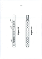
[0023] A FIG. 2A é uma vista em perspectiva de uma lâmina de reagentes conforme descrita neste documento.[0023] FIG. 2A is a perspective view of a reagent slide as described in this document.
[0024] A FIG. 2B é uma vista superior da lâmina de reagentes da FIG. 2A.[0024] FIG. 2B is a top view of the reagent slide of FIG. 2A.
[0025] A FIG. 2C é uma vista inferior da lâmina de reagentes da FIG. 2A.[0025] FIG. 2C is a bottom view of the reagent slide of FIG. 2A.
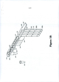
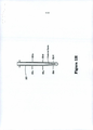
[0026] A FIG. 3 é uma vista plana de uma lâmina de reagentes conforme descrita neste documento.[0026] FIG. 3 is a plan view of a reagent slide as described in this document.
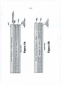
[0027] As FIGs. de 4A a 4E ilustra uma sequência de operações de pipetagem quando do uso de uma camada laminada.[0027] FIGS. 4A to 4E illustrates a sequence of pipetting operations when using a laminated layer.
[0028] As FIGs. 5A e 5B ilustram modalidades de uma camada laminada.[0028] FIGS. 5A and 5B illustrate modalities of a laminated layer.
[0029] As modalidades descritas neste documento propõem suportes de reagentes configurados para conter, transportar e armazenar vários reagentes e materiais usados no preparo e processamento de amostras, por exemplo, amostras clínicas e/ou ambientais. Os suportes de reagentes propostos neste documento trazem várias vantagens ao preparo e ao processamento de amostras, tais como amostras clínicas e/ou ambientais, e são adequados para uso com dispositivos de processamento de amostras automatizados. À guisa de exemplo, algumas das vantagens proporcionadas pelos suportes de reagentes revelados neste documento incluem, entre outras, um modelo que (1) minimiza a contaminação cruzada de reagentes e amostras; (2) facilita o controle de qualidade das lâminas/produtos descartáveis; (3) simplifica a fabricação; e (4) oferece versatilidade útil para diferentes plataformas moleculares e dispositivos automatizados.[0029] The modalities described in this document propose reagent holders configured to contain, transport and store various reagents and materials used in the preparation and processing of samples, for example, clinical and / or environmental samples. The reagent holders proposed in this document have several advantages for sample preparation and processing, such as clinical and / or environmental samples, and are suitable for use with automated sample processing devices. As an example, some of the advantages provided by the reagent holders disclosed in this document include, among others, a model that (1) minimizes the cross contamination of reagents and samples; (2) facilitates the quality control of blades / disposable products; (3) simplifies manufacturing; and (4) offers useful versatility for different molecular platforms and automated devices.
[0030] Os suportes revelados neste documento também sâo configurados para uso por aparelhos que realizam o preparo automatizado de amostras, por exemplo, de várias amostras ao mesmo tempo. Uma forma exemplificativa de um aparelho desse tipo é descrita, por exemplo, na Publicação de Pedido de Patente Internacional na WO 09/054870, a qual se incorpora por referência ao presente documento na íntegra.[0030] The supports disclosed in this document are also configured for use by devices that carry out automated sample preparation, for example, of several samples at the same time. An exemplary form of such an apparatus is described, for example, in the International Patent Application Publication in WO 09/054870, which is incorporated by reference in its entirety into this document.
[0031] O preparo de uma amostra para uso em ensaios, tais como o teste de ácidos nucleicos (“NAT”), por exemplo, por reação em cadeia da polimerase (“PCR”) ou algo do gênero, pode incluir uma ou mais das etapas a seguir: colocar uma amostra de polinucleotídeos em contato com uma mistura de reagentes a fim de realizar o teste de ácidos nucleicos (“NAT”), por exemplo, no caso de uma reação em cadeia por polimerase (“PCR”) ou de outra amplificação que compreenda uma enzima polimerase e vários nucleotídeos. Em algumas modalidades, as misturas de reagentes compreendem ainda sondas de hibridização com grupamentos detectáveis, em que as sondas hibridizam especificamente para visar ácidos nucleicos (e/ou visar por controle positivo sequências de ácidos nucleicos).[0031] The preparation of a sample for use in assays, such as nucleic acid testing ("NAT"), for example, by polymerase chain reaction ("PCR") or the like, may include one or more of the following steps: placing a sample of polynucleotides in contact with a mixture of reagents in order to perform the nucleic acid test (“NAT”), for example, in the case of a polymerase chain reaction (“PCR”) or of another amplification comprising a polymerase enzyme and several nucleotides. In some embodiments, the reagent mixtures further comprise hybridization probes with detectable clusters, where the probes hybridize specifically to target nucleic acids (and / or target nucleic acid sequences by positive control).
[0032] Em algumas modalidades, a mistura de reagentes pode ser na forma de um ou mais grânulos liofilizados, conforme armazenados em um tubo reagente no suporte, e o método pode incluir ainda reconstituir os um ou mais grânulos reagentes com líquido para criar uma solução de mistura de reagentes para PCR. O suporte revelado neste documento proporciona, de maneira auto-contida, todos os reagentes necessários para preparar uma amostra de ácido nucleico pronta para teste, ou, quando fornecido ao usuário na forma de um kit, contém, junto com outras embalagens, todos os reagentes necessários. Reagentes adequados e protocolos para usá-los em extrações de DNA e RNA podem ser encontrados, respectivamente, nas Publicações de Pedido de Patente dos EUA n° US 2010-0009351 e US 2009-0131650, cada uma das quais se incorpora ao presente documento por referência.[0032] In some embodiments, the reagent mixture may be in the form of one or more lyophilized granules, as stored in a reagent tube in the holder, and the method may also include reconstituting the one or more reagent granules with liquid to create a solution mixing reagents for PCR. The support disclosed in this document provides, in a self-contained manner, all the reagents necessary to prepare a sample of nucleic acid ready for testing, or, when supplied to the user in the form of a kit, contains, together with other packages, all reagents needed. Suitable reagents and protocols for using them in DNA and RNA extractions can be found, respectively, in US Patent Application Publications No. US 2010-0009351 and US 2009-0131650, each of which is incorporated into this document by reference.
[0033] Várias características dos suportes de reagentes descritos neste documento são descritas com referência aos desenhos anexos. Cada um dos suportes exemplificativos ilustrados nas FIGs. de IA a 2H, de 2A a 2C e 3 pode ser chamado de “lâmina descartável unificada” ou “lâmina unificada” porque eles sáo destinados ao uso na forma de uma unidade simples configurada para conter todos os reagentes e receptáculos necessários para preparar uma amostra e porque são projetados no formato de uma lâmina. Ê consistente com a descrição deste documento, contudo, que outras estruturas geométricas para os vários receptáculos sejam usadas, de tal modo que a descrição não se limite a uma estrutura linear ou em lâmina, mas possa incluir uma estrutura circular ou em rede.[0033] Various characteristics of the reagent holders described in this document are described with reference to the accompanying drawings. Each of the exemplary supports illustrated in FIGs. from AI to 2H, from 2A to 2C and 3 can be called a "unified disposable blade" or "unified blade" because they are intended for use in the form of a single unit configured to contain all reagents and receptacles necessary to prepare a sample and because they are designed in the shape of a blade. It is consistent with the description in this document, however, that other geometric structures for the various receptacles are used, in such a way that the description is not limited to a linear or blade structure, but may include a circular or network structure.
[0034] Com referência às Figuras de 1 a 3, ilustram-se lâminas de reagentes exemplificativas 100. Uma lâmina de reagentes 100 compreende uma lâmina 110, que possui uma face superior 310 e uma face inferior 320, que abriga vários componentes usados no preparo e/ou processamento de amostras, incluindo uma ou mais bainhas de pipeta 120 e um ou mais tubos de processo 130, e que também abriga um ou mais tubos reagentes integrados 140 com aberturas de tubo reagente 330. Em algumas modalidades, os tubos reagentes 140 são integrados/inteiriços à lâmina 110. Em algumas modalidades, os tubos de processo 130 são integrados à lâmina 110. Em algumas modalidades, os tubos de processo 130 são peças separadas da lâmina unificada. Em algumas modalidades, a lâmina de reagentes compreende um ou mais receptáculos de tubo 150. Os receptáculos de tubo 150 podem ser integrados/inteiriços à lâmina 110 e são configurados para receber um ou mais tubos reagentes 160, os quais não são integrados/inteiriços à lâmina 110. Em algumas modalidades, os tubos reagentes 160 podem ser integrados à lâmina, conforme ilustra a FIG. 2A.[0034] Referring to Figures 1 to 3, exemplary reagent slides 100 are illustrated. A
[0035] À guisa de exemplo, as lâminas de reagentes unificadas, conforme descritas neste documento, podem incluir, por exemplo, 1, 2, 3, 4, 5, 6, 7, 8, 9, 10 ou mais bainhas de pipeta, 1, 2, 3, 4, 5, 6, 7, 8, 9, 10 ou mais tubos de processo, 1, 2, 3, 4, 5, 6, 7, 8, 9, 10 ou mais receptáculos, 1, 2, 3, 4, 5, 6, 7, 8, 9, 10 ou mais tubos reagentes integrados, 1, 2, 3, 4, 5 ou mais recipientes de resíduos, ou algo do gênero, organizados em qualquer configuração na lâmina.[0035] As an example, the unified reagent slides, as described in this document, may include, for example, 1, 2, 3, 4, 5, 6, 7, 8, 9, 10 or more pipette sheaths, 1, 2, 3, 4, 5, 6, 7, 8, 9, 10 or more process tubes, 1, 2, 3, 4, 5, 6, 7, 8, 9, 10 or more receptacles, 1, 2, 3, 4, 5, 6, 7, 8, 9, 10 or more integrated reagent tubes, 1, 2, 3, 4, 5 or more waste containers, or the like, arranged in any configuration on the slide.
[0036] Em modalidades preferidas, a lâmina de reagentes compreende uma ou mais bainhas de pipeta 120 substancialmente separadas de bainhas de pipeta adjacentes e/ou de tubos reagentes 140, tubos de processo 130 ou receptáculos de tubo 150 adjacentes. De preferência, as bainhas de pipeta 120 são integradas à lâmina 110 e, portanto, não requerem a montagem manual na lâmina 110. Pontas de pipeta individuais podem ser inseridas em cada bainha de pipeta individual 120, graças às aberturas de ponta de pipeta individuais 170 presentes na lâmina 110. As bainhas de pipeta 120 circundam substancialmente os lados e a base das pontas de pipeta individuais. O termo “circundar substancialmente”, quando usado com referência às bainhas de pipeta, significa que uma bainha circunda ao menos o corpo principal de uma ponta de pipeta. Ou seja, o topo da ponta de pipeta pode compreender um bocal, ou algo no gênero, (através do qual é inserida a pipeta), o qual se estende além da parte superior da lâmina 110 (e possivelmente repousa no topo desta). Em algumas modalidades, a bainha de pipeta circunda, por exemplo, 70%, 80%, 85%, 80%, 90%, 95% ou mais do comprimento de uma ponta de pipeta. Ao circundar substancialmente pontas de pipeta individuais, as bainhas de pipeta impedem o contato entre cada ponta de pipeta e outras pontas de pipeta, tubos reagentes, tubos de processo, recipientes de resíduos ou algo do gênero presentes na lâmina. Mais especificamente, cada bainha de pipeta é configurada para conter um material que a circunde ou forme uma barreira ou parede 290 que isola o corpo de uma ponta de pipeta inserido nela de outros reagentes/suportes ou produtos descartáveis (por exemplo, de outras pontas de pipeta) na lâmina unificada. Sendo assim, as bainhas de pipeta individuais impedem a contaminação cruzada entre reagentes e/ou amostras manipulados durante o preparo e/ou processamento por pipetagem. Por exemplo, as bainhas de pipeta 120 impedem a contaminação entre pontas de pipeta adjacentes na mesma lâmina, bem como entre pontas de pipeta abrigadas em pontas de reagentes adjacentes, por exemplo, dentro de um dispositivo de preparo/processamento de amostras automatizado.[0036] In preferred embodiments, the reagent slide comprises one or
[0037] Em algumas modalidades, as bainhas de pipeta contêm uma ou mais aberturas de bainha ou orifícios com núcleo 180. Em algumas modalidades, os orifícios com núcleo 180 se fazem presentes na forma de pares de aberturas de bainha, ao passo que, em outras modalidades, os orifícios com núcleo não fazem parte de um par de aberturas. Em algumas modalidades, as bainhas de pipeta compreendem um, dois, três, quatro, cinco, seis, sete, oito, nove, dez ou mais orifícios com núcleo sem par 180. Em algumas modalidades, as bainhas de pipeta compreendem vários pares de aberturas, cada um dos quais compreende dois orifícios com núcleo 180. Por exemplo, uma bainha de pipeta pode incluir um par, dois pares, três pares, quatro pares, cinco pares, seis pares, sete pares, oito pares, nove pares, dez pares ou mais pares de aberturas nela. Um par de aberturas em uma bainha de pipeta compreende um primeiro orifício com núcleo 180a e um segundo orifício com núcleo 180b, os quais são formados de lados opostos e à mesma distância em relação ao topo da bainha de pipeta 120, conforme ilustra, por exemplo, a FIG. 1E. Em algumas modalidades, orifícios com núcleo sem par 180 são formados de lados opostos, mas a distâncias variadas em relação ao topo da bainha de pipeta 120.[0037] In some embodiments, the pipette sheaths contain one or more sheath openings or 180-core holes. In some embodiments, the 180-core holes are present in the form of pairs of sheath openings, whereas in in other embodiments, the core holes are not part of a pair of openings. In some embodiments, the pipette sheaths comprise one, two, three, four, five, six, seven, eight, nine, ten or more orifices with a
[0038] Os orifícios com núcleo 180, sejam sem par ou dispostos na forma de um ou mais pares de aberturas, podem, para maior vantagem, ser usados para determinar a presença ou ausência de uma ponta de pipeta dentro de uma bainha de pipeta 120, seja manualmente (por inspeção visual) ou automaticamente (por exemplo, por um sensor óptico). Dessa forma, os orifícios com núcleo 180 possibilitam um ponto de verificação de controle de qualidade adicional antes do uso da lâmina de reagentes unificada. Por exemplo, no contexto da detecção automatizada de pontas de pipeta, quando dois orifícios com núcleo 180 assumem a forma de um par de aberturas na bainha de pipeta, emite-se luz através do primeiro orifício com núcleo desse par. Quando a bainha de pipeta 120 não abriga uma ponta de pipeta, a luz atravessa os orifícios com núcleo primeiro e segundo do par de aberturas alinhadas formadas de lados opostos da bainha. Quando uma ponta de pipeta se faz presente dentro da bainha, a ponta de pipeta bloqueia ou obstrui a via visível entre os orifícios com núcleo primeiro e segundo de cada par de aberturas. Sendo assim, os pares de aberturas de bainha 180 podem ser prontamente usados para determinar se há ou não uma ponta de pipeta presente em cada bainha 120. Quando orifícios com núcleo 180 se fazem presentes, mas não como parte de um par de aberturas na bainha de pipeta, é possível determinar a presença ou ausência de uma ponta de pipeta dentro da bainha calculando, por exemplo, o reflexo ou a obstrução da luz emitida através do orifício com núcleo sem par, visto que o reflexo ou obstrução serão diferentes se uma ponta de pipeta estiver presente ou ausente dentro da bainha de pipeta. Por exemplo, em algumas modalidades, a detecção do reflexo da luz pode ser determinada usando meios e dispositivos reconhecidos na técnica como detectores retrorrefletivos. Em algumas modalidades, determina-se a presença ou ausência de uma ponta de pipeta em uma bainha medindo-se a obstrução da luz, por exemplo, usando meios e dispositivos reconhecidos na técnica, tais como sensores de feixe passante.[0038] Orifices with
[0039] Como mencionado, em algumas modalidades, mais de um par de aberturas de bainha de pipeta 180 se faz presente na bainha, conforme ilustra, por exemplo, a FIG. 1E. Quando vários orifícios com núcleo 180 são formados em uma bainha de pipeta (por exemplo, 2, 3, 4, 5, 6, 7, 8, 9, 10 ou mais), cada orifício com núcleo é formado em uma posição ou a uma distância diferentes ao longo do comprimento da bainha de pipeta em relação à face superior da lâmina 110, a qual define a abertura de ponta de pipeta. À semelhança, vários pares de aberturas de bainha 180 podem ser formados ao longo do comprimento de uma mesma bainha de pipeta, cada par de aberturas de bainha 180 disposto em uma posição ou a uma distância diferentes ao longo do comprimento da bainha de pipeta 120 em relação à face superior da lâmina 110, a qual define a abertura de ponta de pipeta. A distribuição de vários orifícios com núcleo 180 ao longo do comprimento de uma bainha de pipeta (sejam sem par ou como parte de um par de aberturas de bainha de pipeta) possibilita não só determinar se uma ponta de pipeta se faz ou não presente dentro da bainha, mas também determinar o comprimento (tamanho) de uma ponta de pipeta inserida na bainha. Por exemplo, quando uma ponta de pipeta mais curta se faz presente na bainha 120, ela pode alterar o reflexo ou a obstrução da luz emitida através do orifício com núcleo 180a mas pode ser curta demais para alterar o reflexo ou a obstrução da luz emitida através do orifício com núcleo 180d. Da mesma forma, quando vários pares de aberturas de bainha se fazem presentes, uma ponta presente na bainha de pipeta pode obstruir a passagem da luz emitida através do orifício com núcleo 180a à medida que deixa o orifício com núcleo 180b mas pode ser curta demais para obstruir a luz que atravessa os pares de aberturas de bainha 180c-180d ou 180e-180f. Os pares de aberturas de bainha de pipeta 180, portanto, trazem vantagens ao controle de qualidade das lâminas de reagentes porque permitem determinar com rapidez a presença ou ausência de pontas, o que pode ser feito manualmente (por exemplo, pela inspeção visível por um indivíduo) ou pode ser automatizado prontamente durante o processo de fabricação ou o processo de montagem das lâminas de reagentes. Por exemplo, é possível usar sensores ópticos para transmitir e detectar a luz que entra ou deixa os orifícios com núcleo primeiro ou segundo dos pares de aberturas 180 a fim de detectar a presença ou ausência (e, por exemplo, o comprimento) de pontas de pipeta dentro de cada bainha individual 120.[0039] As mentioned, in some embodiments, more than one pair of
[0040] Além de trazer vantagens ao controle de qualidade, os orifícios com núcleo 180 podem facilitar a fabricação das lâminas de reagentes 100. Mais especificamente, a fabricação de bainhas longas e relativamente estreitas, como as bainhas de pipeta 120, por moldagem por injeção traz desafios significativos. As bainhas de pipeta normalmente são de formato longo e estreito com vasos pouco angulados. Pinos centrais longos, os quais são convencionalmente usados na moldagem por injeção de estruturas como as bainhas de ponta de pipeta conforme descritas neste documento, tendem a se deslocar com a injeção sob alta pressão, por exemplo, do material termoplástico ou termofixo do qual as lâminas de reagentes são feitas. A presença de orifícios com núcleo 180, sejam sem par ou como parte de pares de aberturas de bainha, permite o uso de pinos estabilizantes, produzidos por moldagem, para ser usados a fim de estabilizar os pinos centrais longos usados para a moldagem das bainhas de pipeta 120. Logo, os orifícios com núcleo 180 viabilizam a fabricação de bainhas de pipeta unificadas por moldagem por injeção, simplificando e diminuindo assim os custos de fabricação.[0040] In addition to bringing advantages to quality control, holes with
[0041] Em algumas modalidades, a lâmina de reagentes compreende bainhas de pipeta com o mesmo comprimento. Em algumas modalidades, a lâmina de reagentes pode compreender bainhas de pipeta com comprimentos diferentes. Por exemplo, conforme ilustra a FIG. 2, a lâmina de reagentes 100 compreende uma ou mais bainhas de pipeta 140 com um primeiro comprimento 230 e uma ou mais bainhas de pipeta com um segundo comprimento 240, conforme ilustra, por exemplo, a FIG. 2A. Sendo assim, as bainhas de pipeta com o primeiro comprimento 230, mais longo, podem abrigar pontas de pipeta mais longas do que as bainhas de pipeta com o segundo comprimento 240, mais curto. Conforme discutido acima, em algumas modalidades, as bainhas de pipeta compreendem um ou mais orifícios com núcleo sem par 180 ou orifícios com núcleo na forma de pares de aberturas de bainha de pipeta. Em algumas modalidades, contudo, as bainhas de pipeta não compreendem nenhum orifício com núcleo 180. Em algumas modalidades, por exemplo, propõe-se uma lâmina de reagentes que compreende uma ou mais bainhas de pipeta com um primeiro comprimento, mais longo, e com pares de aberturas de bainha de pipeta ao longo desse comprimento mais longo; e uma ou mais bainhas de pipeta com um segundo comprimento, mais curto, e nenhum orifício com núcleo ou par de aberturas de bainha de pipeta. Em algumas modalidades, contudo, ambas as bainhas de pipeta mais longas e mais curtas compreendem ao menos um orifício com núcleo sem par 180 ou ao menos um par de aberturas de bainha de pipeta. Em algumas modalidades, a bainha de pipeta mais longa compreende mais orifícios com núcleo sem par 180 ou pares de aberturas de bainha de pipeta do que a bainha de pipeta mais curta. À guisa de exemplo, uma bainha de pipeta mais curta pode conter um ou dois orifícios com núcleo 180, ou um ou dois pares de aberturas de bainha de pipeta, e uma bainha de pipeta mais longa pode conter três ou quatro orifícios com núcleo sem par 180, ou três ou quatro pares de aberturas de bainha de pipeta.[0041] In some embodiments, the reagent slide comprises pipette sheaths of the same length. In some embodiments, the reagent slide may comprise pipette sheaths of different lengths. For example, as shown in FIG. 2, the
[0042] Conforme ilustra a FIG. 3, as bainhas de pipeta 120 são fechadas na base, o que proporciona espaço para coletar quaisquer líquidos ou gotejamentos oriundos das pontas de pipeta após o uso. As bainhas de pipeta individuais são substancialmente separadas, por exemplo, por uma parede.[0042] As shown in FIG. 3, the
[0043] Conforme discutido acima, as lâminas de reagentes reveladas neste documento compreendem, de preferência, um ou mais receptáculos 150. Os receptáculos 150 da lâmina de reagentes podem ser configurados para receber tubos reagentes que contêm, respectivamente, quantidades suficientes de um ou mais reagentes usados para preparar e/ou processar as amostras biológicas e/ou ambientais. Em algumas modalidades, os reagentes podem estar em forma sólida, tal como na forma liofilizada, para realizar o preparo e/ou o processamento de amostras, por exemplo, o isolamento de ácidos nucleicos de uma amostra para criar uma amostra adequada para o teste de ácidos nucleicos (“NAT”) associada ao suporte. Em algumas modalidades, os reagentes podem estar na forma líquida.[0043] As discussed above, the reagent slides disclosed in this document preferably comprise one or
[0044] Os um ou mais receptáculos 150 podem ser do mesmo tamanho e formato, ou podem ser de tamanhos e formatos diferentes uns dos outros. Os receptáculos 150 são ilustrados com bases abertas, mas não se limitam a essa topologia, e podem ser fechados, a não ser pela entrada 220 na face superior da lâmina 110. De preferência, os receptáculos 150 são configurados para receber recipientes, vasos ou tubos de uso comum no campo das análises em laboratório, ou recipientes adequadamente configurados para uso com o suporte revelado neste documento. Sendo assim, os tubos reagentes 160, os quais não são integrados à lâmina 110, podem ser armazenados à parte das lâminas de reagentes e encaixados nestas imediatamente antes do uso. Isso é vantajoso porque diferentes reagentes (por exemplo, reagentes para extração de ácidos nucleicos vs. reagentes para PCR) podem exigir condições de armazenamento diferentes. Por exemplo, reagentes liofilizados podem ser sensíveis à umidade e exigir condições de armazenamento diferentes, por exemplo, de um tampão de lise. O modelo com encaixe rápido de tubos reagentes também traz versatilidade, visto que tubos contendo diferentes reagentes podem ser montados na lâmina de reagentes 100 dependendo dos diferentes tipos de preparo/processamento que o usuário deseja realizar com a amostra.[0044] The one or
[0045] As lâminas reveladas neste documento podem incluir uma borda dianteira 190. A borda dianteira 190 pode ser configurada para facilitar o manuseio por parte do usuário. A borda dianteira 190 também pode ser configurada para facilitar a introdução e/ou o posicionamento adequados da lâmina de reagentes 100, por exemplo, em um dispositivo de preparo e processamento automatizado. A borda dianteira 190 pode conter certos recursos de identificação, tais como cor, código de barras, RFID ou algo do gênero, para facilitar a identificação e/ou o monitoramento das lâminas de reagentes 100 individuais.[0045] The blades disclosed in this document may include a
[0046] Em algumas modalidades, a lâmina de reagentes 100 compreende um membro de posicionamento, tal como uma chave mecânica 250. Normalmente, essa chave faz parte da lâmina 100, por exemplo, parte da borda dianteira 190 ou algo do gênero. Uma chave mecânica garante a recepção do suporte em um membro complementar, por exemplo, em um bastidor de suporte ou em um compartimento receptor de um aparelho que controla as operações de pipetagem sobre os reagentes no suporte. Uma chave mecânica 250 normalmente é um recorte de formato específico que coincide com um recorte ou protuberância correspondente em um aparelho receptor. Sendo assim, a lâmina de reagentes 100 pode compreender uma chave mecânica 250 que consiste em um par de recortes retangulares na extremidade da lâmina 110. Esse recurso, conforme ilustrado, proporciona também uma aba pela qual o usuário pode obter uma vantagem mecânica adequada para inserir e remover o suporte de um bastidor ou de outro aparelho. Os versados na técnica perceberão que a localização do recurso da chave mecânica 250 pode ser diferente da ilustrada nas Figuras anexas. Por exemplo, a chave mecânica 250 pode ser situada na outra extremidade da lâmina 110, que não a borda dianteira 190. Em algumas modalidades, a chave 250 é um recorte angulado que facilita a introdução do suporte em um bastidor, bem como garante uma boa colocação no bastidor ao posicionar um recorte angulado complementar em uma área rebaixada configurada para recebê-lo. Outras variações de uma chave mecânica são, decerto, consistentes com a descrição neste documento: por exemplo, recortes curvados ou várias combinações de entalhes ou protuberâncias, todos facilitariam o posicionamento seguro do suporte.[0046] In some embodiments, the
[0047] Em algumas modalidades, a lâmina de reagentes compreende um identificador fixado na lâmina 100. O identificador pode ser uma etiqueta, tal como uma etiqueta gravável, um código de barras, um código de barras bidimensional ou uma etiqueta de RFID. O identificador serve, por exemplo, para revelar com rapidez qual combinação de reagentes está presente no suporte e, assim, a qual tipo de protocolo de preparo de amostras se destina. O identificador também pode indicar o lote do qual o suporte foi produzido, para fins de controle de qualidade e manutenção de registros. O identificador também pode permitir que o usuário correlacione um suporte específico a uma amostra específica.[0047] In some embodiments, the reagent slide comprises an identifier attached to slide 100. The identifier can be a label, such as a writable label, a bar code, a two-dimensional bar code or an RFID tag. The identifier serves, for example, to quickly reveal which combination of reagents is present in the holder and, thus, what type of sample preparation protocol is intended. The identifier can also indicate the batch from which the support was produced, for the purposes of quality control and record keeping. The identifier can also allow the user to correlate specific support to a specific sample.
[0048] Conforme discutido acima, tubos reagentes 140 e 160, tais como contendo os reagentes liofilizados, podem ser lacrados no topo por uma folha metálica, tal como uma folha de alumínio, sem nenhuma camada de forro plástico, conforme descrito em mais detalhes neste documento. Tubos reagentes 160 contendo reagentes podem ser fornecidos na forma de tubos simples ou de vários tubos com vasos completamente distintos, em que os vasos são unidos, por exemplo, por meio de um conector. Por exemplo, em algumas modalidades, mais de um tubo reagente 160 (por exemplo, dois, três, quatro, cinco, seis, sete, oito, nove, dez ou mais) podem ser fornecidos juntos, em que os tubos reagentes são encaixados juntos no lugar em receptáculos 150 adjacentes. À guia de exemplo, vários tubos reagentes 160 contendo reagentes específicos para um ensaio de NAT específico (por exemplo, contendo oligonucleotídeos iniciadores de amplificação liofilizados e/ou sondas e/ou ácidos nucleicos de controle) podem ser unidos uns aos outros e prontamente encaixados em uma lâmina 110 configurada para receber os vários tubos reagentes diferentes unidos juntos. Em outras modalidades, os receptáculos são configurados para que seja possível inserir tubos reagentes 160 individualmente em cada receptáculo 150.[0048] As discussed above,
[0049] Tubos reagentes integrados 140 e/ou tubos reagentes de encaixe rápido 160 contendo diferentes reagentes podem ser de cores diferentes ou codificados por coloração para facilitar a identificação por parte do usuário. Por exemplo, tubos reagentes integrados 140 coloridos podem ser úteis para distinguir diferentes tipos de lâminas de reagentes unificadas, por exemplo, que podem ser usadas em diferentes preparados de amostra. No caso dos tubos reagentes de encaixe rápido 160, a codificação por coloração dos tubos pode ser usada para distinguir diferentes reagentes uns dos outros. À guisa de exemplo, no caso de lâminas de reagentes unificadas usadas para o isolamento de DNA e a geração de uma amostra pronta para PCR, diferentes tubos reagentes codificados por coloração 160 podem ser usados para distinguir tubos usados com relação a diferentes NATs, por exemplo, com diferentes pares de oligonucleotídeos iniciadores, e seus semelhantes. Por exemplo, eles podem ser feitos de materiais de cores diferentes, tais como plástico tingido, ou podem ter algum tipo de marca identificadora neles, tal como uma listra ou ponto colorido. Eles também podem ter uma etiqueta impressa na lateral e/ou podem ter um identificador, tal como um código de barras, na camada de lacre no topo. Em algumas modalidades, os tubos de processo 130 e/ou os tubos reagentes 140 e 160 podem ser translúcidos.[0049]
[0050] As lâminas de reagentes 100 são ilustradas com uma câmara de resíduos 200, a qual inclui uma abertura para a entrada de resíduos 210 na face superior da lâmina 110. A câmara de resíduos 200 é opcional e, nas modalidades em que se faz presente, é configurada para receber reagentes líquidos usados. Em outras modalidades, nas quais não se faz presente, os reagentes líquidos usados são transferidos e eliminados em um local fora do suporte, tal como, por exemplo, um tubo de amostras que continha a amostra original cujo conteúdo foi analisado. A câmara de resíduos 200 é ilustrada como parte de um conjunto que compreende também dois ou mais tubos reagentes 140. Deve-se ter em mente que essa estrutura é construída para fins de conveniência, por exemplo, de fabricação; outras localizações da câmara de resíduos 200 são possíveis, tais como modalidades nas quais a câmara de resíduos 200 é adjacente a um tubo reagente 140, mas não conectada a ele senão pela lâmina 110.[0050] The reagent slides 100 are illustrated with a
[0051] O suporte tipicamente é tal que a lâmina 110, as uma ou mais bainhas de pipeta 120, o tubo de processo 130, os dois ou mais tubos reagentes 140 e a câmara de resíduos (se presente) sejam feitos de uma peça inteiriça, feita de um material tal como polipropileno. Conforme discutido acima, o modelo das modalidades reveladas neste documento facilita vantajosamente a fabricação de uma lâmina de reagentes unificada, por exemplo, por moldagem por injeção.[0051] The support is typically such that the slide 110, the one or
[0052] As FIGs. 1G e 2C ilustram a face inferior 320 da lâmina de reagentes 100. Conforme ilustra a FIG. 2C, a face inferior 320 compreende escoras 300, as quais proporcionam estabilidade e flexibilidade.[0052] FIGS. 1G and 2C illustrate the
[0053] A Figura 1H ilustra uma vista em corte de uma ponta de pipeta 360 contida em uma das bainhas de pipeta 120.[0053] Figure 1H illustrates a sectional view of a pipette tip 360 contained in one of the
[0054] Embora as Figuras anexas a este documento ilustrem uma lâmina configurada para que as uma ou mais bainhas de pipeta, os um ou mais receptáculos e as respectivas aberturas do tubo de processo e dos tubos reagentes sejam todos dispostos linearmente em relação uns aos outros (isto é, com pontos médios no mesmo eixo), os versados na técnica perceberão que os suportes revelados neste documento não se limitam a configurações específicas de receptáculos, câmaras de resíduos, tubos de processo, bainhas de pipeta e tubos reagentes. Por exemplo, algumas modalidades propõem uma lâmina de reagentes mais curta, por exemplo, com aberturas escalonadas, em que algum reagente, tubo de processo ou aberturas de ponta de pipeta ocupam posições “deslocadas do eixo”. Os vários receptáculos etc. também não precisam ocupar as mesmas posições em relação uns aos outros, conforme ilustram as FIGs. de 1 a 3, nas quais o tubo de processo é disposto aproximadamente próximo do meio do suporte, reagentes líquidos são armazenados em receptáculos montados de um lado do tubo de processo e receptáculos contendo reagentes sólidos são montados do outro lado do tubo de processo. Sendo assim, nas FIGs. de 1 a 3, o tubo de processo fica em uma extremidade da lâmina e as bainhas de pipeta ficam na outra extremidade, internamente adjacentes a uma câmara de resíduos e a dois ou mais tubos reagentes. Ainda outras disposições são possíveis, tais como dispondo o tubo de processo em uma extremidade do suporte, dispondo o tubo de processo adjacente às pontas de pipeta e bainhas de ponta de pipeta (conforme descrito em mais detalhes neste documento) e dispondo o tubo de resíduos adjacente ao tubo de processo. Perceber-se-á que configurações alternativas das várias partes da lâmina de reagentes dão origem somente a variações de forma e podem ser enquadradas em outras variações do aparelho conforme descrito, incluindo, entre outros, conjuntos de instruções alternativas para o preparo e processamento automatizados das amostras.[0054] Although the Figures attached to this document illustrate a slide configured so that the one or more pipette sheaths, the one or more receptacles and the respective openings of the process tube and reagent tubes are all arranged linearly in relation to each other (that is, with midpoints on the same axis), those skilled in the art will realize that the supports disclosed in this document are not limited to specific configurations of receptacles, waste chambers, process tubes, pipette sheaths and reagent tubes. For example, some modalities propose a shorter reagent layer, for example, with staggered openings, in which some reagent, process tube or pipette tip openings occupy positions "offset from the axis". The various receptacles etc. they also do not need to occupy the same positions in relation to each other, as illustrated by FIGs. 1 to 3, in which the process tube is arranged approximately close to the support medium, liquid reagents are stored in receptacles mounted on one side of the process tube and receptacles containing solid reagents are mounted on the other side of the process tube. Therefore, in FIGs. from 1 to 3, the process tube is at one end of the slide and the pipette sheaths are at the other end, internally adjacent to a waste chamber and two or more reagent tubes. Still other arrangements are possible, such as arranging the process tube at one end of the holder, arranging the process tube adjacent to the pipette tips and pipette tip sheaths (as described in more detail in this document) and arranging the waste tube adjacent to the process tube. It will be realized that alternative configurations of the various parts of the reagent slide give rise only to variations in shape and can be framed in other variations of the apparatus as described, including, among others, sets of alternative instructions for the automated preparation and processing of samples.
[0055] O tubo de processo 130 também pode ser um tubo de encaixe rápido, em vez de parte de uma peça inteiriça. O tubo de processo 130 pode ser usado em vários processos de mistura e reação que ocorrem durante o preparo das amostras. Por exemplo, a lise celular pode ocorrer no tubo de processo 130, assim como a extração de ácidos nucleicos. O tubo de processo 130 é, então, posicionado vantajosamente em um local que minimize, em geral, operações que causem o movimento da cabeça de pipeta envolvidas na transferência de líquidos ao tubo de processo 130.[0055]
[0056] Os tubos reagentes 140 normalmente são configurados para conter vários reagentes líquidos. Por exemplo, em algumas modalidades, as lâminas de reagentes podem compreender três tubos reagentes, em que os tubos reagentes individuais são munidos de um tampão de lavagem de amostras, um tampão de liberação de ácidos nucleicos e um tampão de neutralização de ácidos nucleicos, por exemplo, para purificar os ácidos nucleicos para ensaios de NAT.[0056]
[0057] Os tubos reagentes 140 que contêm líquidos ou reagentes líquidos podem ser lacrados por uma estrutura laminada 400. A estrutura laminada pode compreender uma camada de vedação térmica, uma camada plástica, tal como uma camada de polipropileno, e uma camada de metal, tal como uma folha de alumínio, em que a camada de vedação térmica é adjacente aos um ou mais tubos reagentes 140. O filme plástico adicional usado em um laminado para receptáculos com reagentes líquidos serve tipicamente para impedir que o líquido entre em contato com o alumínio.[0057]
[0058] As modalidades exemplificativas de uma estrutura laminada 400, que diferem em suas estruturas de camada, são descritas, por exemplo, na Publicação de Pedido de Patente dos EUA na 2009/0129978, incorporada a este documento por referência. Em algumas modalidades, a camada de vedação térmica da estrutura laminada 400 é feita, por exemplo, de uma laca ou de outro polímero com ponto de fusão baixo e situa-se no topo da lâmina de reagentes 100 quando assim aplicada, conforme ilustra a FIG. 5A. A estrutura laminada 400 pode incluir uma camada plástica 420 sobre a camada de vedação térmica 410, a qual é feita de polipropileno e cuja espessura é na faixa de 10 a 50 microns. A estrutura laminada 400 também pode incluir uma camada de metal sobre a camada plástica, a qual compreende uma camada de folha de alumínio 440 ligada à camada plástica 420 por uma camada de adesivo 430. Como alternativa, a camada de metal pode ser uma camada de metal evaporada ou pulverizada no lugar diretamente sobre a camada plástica, conforme ilustra a FIG. 5B.[0058] The exemplary modalities of a laminated structure 400, which differ in their layer structures, are described, for example, in the US Patent Application Publication 2009/0129978, incorporated by reference into this document. In some embodiments, the heat seal layer of laminated structure 400 is made, for example, of a lacquer or other polymer with a low melting point and is located on top of the
[0059] Os laminados implementados neste documento facilitam o armazenamento a longo prazo porque o suporte inclui a presença de reagentes liofilizados vedados, bem como líquidos vedados em íntima proximidade, o que normalmente é difícil de obter.[0059] The laminates implemented in this document facilitate long-term storage because the support includes the presence of sealed lyophilized reagents, as well as sealed liquids in close proximity, which is normally difficult to obtain.
[0060] Em uma modalidade, o topo dos tubos reagentes possui bordas chanfradas, de tal modo que, quando uma folha de alumínio for ligada termicamente ao topo, o plástico fundido não se estenda além da borda externa do tubo. Isso é vantajoso porque, se o plástico fundido diminuir o diâmetro interno do tubo, ele causará interferência à ponta de pipeta durante a operação. Em outras modalidades, uma parte plana saliente 260 facilita a aplicação e remoção do laminado 400. A superfície saliente 260, a qual é disposta na face superior do membro de conexão e a qual circunda as aberturas de entrada dos tubos reagentes e, como opção, a câmara de resíduos, é uma característica opcional do suporte.[0060] In one embodiment, the top of the reagent tubes has beveled edges, such that when an aluminum sheet is thermally bonded to the top, the molten plastic does not extend beyond the outer edge of the tube. This is advantageous because, if the molten plastic decreases the inner diameter of the tube, it will cause interference to the pipette tip during operation. In other embodiments, a flat protruding part 260 facilitates the application and removal of laminate 400. The protruding surface 260, which is arranged on the upper face of the connecting member and which surrounds the inlet openings of the reagent tubes and, as an option, the waste chamber, is an optional feature of the support.
[0061] A maneira pela qual o líquido é pipetado para fora é tal que uma ponta de pipeta perfurando através da folha rasgue sem criar uma vedação em torno da ponta de pipeta. Uma vedação em torno da ponta durante a pipetagem seria desvantajosa porque certa quantidade de fluxo de ar é desejável para a operação de pipetagem. Neste caso, não se forma uma vedação porque a estrutura laminada 400 faz com que a folha perfurada permaneça na posição inicialmente adotada quando perfurada. Os cinco quadros superiores na FIG. 4 ilustram a pipetagem de um reagente para fora a partir de um tubo reagente com um laminado, conforme descrito em mais detalhes neste documento. Em A, posiciona-se a ponta de pipeta aproximadamente no centro sobre o tubo reagente 140, o qual contém o reagente 270. Em B, abaixa-se a ponta de pipeta, normalmente de maneira controlada, ao tubo reagente e, ao fazê-lo, perfura-se a folha 280. A vista explodida dessa área ilustra a borda do laminado perfurado em contato com a ponta de pipeta na região mais larga em que ela penetra no tubo reagente. Em C, a ponta de pipeta é retirada aos poucos, mantendo-se a ponta dentro da concentração de reagente 270. A vista explodida ilustra que a folha perfurada manteve a configuração que adotou quando foi perfurada e a ponta de pipeta desceu à sua posição mais funda dentro do tubo reagente. Em D, a ponta de pipeta absorve o reagente 270, possivelmente alterando a altura deste dentro dela. Em E, a ponta de pipeta é removida por inteiro do tubo reagente.[0061] The way in which the liquid is pipetted out is such that a pipette tip piercing through the sheet will tear without creating a seal around the pipette tip. Sealing around the tip during pipetting would be disadvantageous because a certain amount of air flow is desirable for the pipetting operation. In this case, a seal is not formed because the laminated structure 400 causes the perforated sheet to remain in the position initially adopted when perforated. The top five frames in FIG. 4 illustrate pipetting a reagent out of a reagent tube with a laminate, as described in more detail in this document. In A, the pipette tip is positioned approximately in the center on the
[0062] Os materiais dos vários tubos e câmaras podem ser configurados para ter ao menos uma superfície interna uniforme e um revestimento da superfície interna que diminua a ligação de ácidos nucleicos e outras macromoléculas a ela. A ligação de ácidos nucleicos é indesejada por causa da possibilidade de causar uma menor sensibilidade na detecção e na análise subsequentes dos ácidos nucleicos que não estão presos na superfície do suporte. O tubo de processo também pode ter uma superfície de baixa ligação e permitir que contas magnéticas corram para cima e para baixo dentro da parede facilmente, sem se prender a ela. Ademais, ele possui um revestimento de superfície hidrófobo, o qual permite o atrito estático dos fluidos e, portanto, a baixa ligação de ácidos nucleicos e outras moléculas. As lâminas de reagentes reveladas neste documento podem ser feitas de muitos polímeros diferentes, incluindo todos os termoplásticos, alguns termofixos e elastômeros. De preferência, o material é adequado para a moldagem por injeção. Exemplos não limitantes de polímeros úteis na fabricação das lâminas reveladas neste documento incluem, por exemplo, polímeros de epóxi e fenólicos, náilon, polímeros de polietileno e de poliestireno, e seus semelhantes. De preferência, as lâminas de reagentes são feitas de um plástico, tal como polipropileno, e são de dimensões rígidas, de tal modo que as lâminas de reagentes não percam significativamente a firmeza ou se flexionem significativamente sob seu próprio peso nem se deformem facilmente durante o manuseio e transporte rotineiros e, portanto, não permitam o vazamento de reagentes a partir delas.[0062] The materials of the various tubes and chambers can be configured to have at least a uniform internal surface and an internal surface coating that decreases the binding of nucleic acids and other macromolecules to it. The binding of nucleic acids is undesirable because of the possibility of causing less sensitivity in the subsequent detection and analysis of nucleic acids that are not trapped on the surface of the support. The process tube can also have a low bond surface and allow magnetic beads to run up and down inside the wall easily, without sticking to it. In addition, it has a hydrophobic surface coating, which allows static friction of fluids and, therefore, low binding of nucleic acids and other molecules. The reagent slides disclosed in this document can be made of many different polymers, including all thermoplastics, some thermosets and elastomers. Preferably, the material is suitable for injection molding. Non-limiting examples of polymers useful in making the sheets disclosed in this document include, for example, epoxy and phenolic polymers, nylon, polyethylene and polystyrene polymers, and the like. Preferably, the reagent slides are made of a plastic, such as polypropylene, and are of rigid dimensions, such that the reagent slides do not significantly lose their firmness or flex significantly under their own weight or deform easily during the process. routine handling and transportation and therefore do not allow leakage of reagents from them.
[0063] Além disso, deve-se considerar consistente com a descrição revelada neste documento que um suporte seja configurado também para receber uma amostra, tal como em um tubo de amostra. Sendo assim, em modalidades descritas em outras partes, um bastidor recebe uma série de tubos de amostra e uma série de suportes correspondentes de tal modo que os tubos de amostra e suportes sejam dispostos em separado e independentemente uns dos outros. Todavia, em outras modalidades, um suporte pode ser configurado para receber também uma amostra, por exemplo, em um tubo de amostra. E, assim, um bastidor complementar é configurado para aceitar uma série de suportes, em que cada suporte possui uma amostra, além de reagentes e outros itens. Nessa modalidade, o suporte é configurado para que a amostra seja acessível a um verificador de identificação de amostras.[0063] In addition, it should be considered consistent with the description revealed in this document that a support is also configured to receive a sample, such as in a sample tube. Thus, in embodiments described elsewhere, a rack receives a series of sample tubes and a series of corresponding supports in such a way that the sample tubes and supports are arranged separately and independently of each other. However, in other embodiments, a holder can be configured to also receive a sample, for example, in a sample tube. Thus, a complementary rack is configured to accept a series of supports, in which each support has a sample, in addition to reagents and other items. In this modality, the support is configured so that the sample is accessible to a sample identification tester.
[0064] As lâminas de reagentes descritas neste documento podem ser fornecidas na forma de um kit. Por exemplos, lâminas de reagentes individuais podem ser embaladas juntas ou individualmente em uma bolsa lacrada para diminuir o risco de que ar e umidade entrem em contato com os reagentes no suporte. Essa bolsa lacrada pode conter um ou mais dos suportes descritos neste documento, tal como 2, 4, 6, 8, 10, 12, 16, 20 ou 24 suportes.[0064] The reagent slides described in this document can be supplied in the form of a kit. For example, individual reagent slides can be packed together or individually in a sealed pouch to reduce the risk that air and moisture will come in contact with the reagents in the holder. This sealed pouch may contain one or more of the supports described in this document, such as 2, 4, 6, 8, 10, 12, 16, 20 or 24 supports.
[0065] O suporte também pode ser fornecido como parte de um kit para preparar amostras, em que o kit compreende uma primeira bolsa, a qual contém um ou mais dos suportes descritos neste documento, cada um dos suportes sendo configurado com reagentes líquidos para, por exemplo, lise, lavagem e liberação, e uma segunda bolsa, a qual contém uma atmosfera inerte dentro dela, e um ou mais tubos reagentes contendo reagentes para PCR liofilizados. Esse kit também pode ser configurado para possibilitar a análise de várias amostras e conter reagentes para PCR suficientes (ou outros reagentes de amplificação, tais como para RT-PCR, amplificação mediada por transcrição, amplificação por deslocamento de fitas, NASBA, amplificação dependente da helicase, outros reagentes familiares aos versados na técnica e outros reagentes descritos neste documento) para processar essas amostras e uma série de suportes individuais, tal como 2, 4, 6, 8, 10, 12, 16, 20 ou 24 suportes.[0065] The holder can also be provided as part of a sample preparation kit, in which the kit comprises a first pouch, which contains one or more of the supports described in this document, each of the supports being configured with liquid reagents for, for example, lysis, washing and release, and a second bag, which contains an inert atmosphere within it, and one or more reagent tubes containing lyophilized PCR reagents. This kit can also be configured to allow analysis of multiple samples and contain sufficient PCR reagents (or other amplification reagents, such as for RT-PCR, transcription-mediated amplification, tape shift amplification, NASBA, helicase dependent amplification , other reagents familiar to those skilled in the art and other reagents described in this document) to process those samples and a series of individual supports, such as 2, 4, 6, 8, 10, 12, 16, 20 or 24 supports.
Claims (29)
Applications Claiming Priority (3)
| Application Number | Priority Date | Filing Date | Title |
|---|---|---|---|
| US201161541991P | 2011-09-30 | 2011-09-30 | |
| US61/541,991 | 2011-09-30 | ||
| PCT/US2012/058102 WO2013049706A1 (en) | 2011-09-30 | 2012-09-28 | Unitized reagent strip |
Publications (2)
| Publication Number | Publication Date |
|---|---|
| BR112014007440A2 BR112014007440A2 (en) | 2017-04-04 |
| BR112014007440B1 true BR112014007440B1 (en) | 2020-11-03 |
Family
ID=47046870
Family Applications (1)
| Application Number | Title | Priority Date | Filing Date |
|---|---|---|---|
| BR112014007440-2A BR112014007440B1 (en) | 2011-09-30 | 2012-09-28 | unified reagent slide and methods for detecting the presence or absence of a pipette tip within a pipette sheath and for determining the length of a pipette tip within a pipette sheath in it |
Country Status (12)
| Country | Link |
|---|---|
| US (3) | US9222954B2 (en) |
| EP (2) | EP2761305B1 (en) |
| JP (2) | JP6117217B2 (en) |
| KR (1) | KR102121853B1 (en) |
| CN (2) | CN103959070B (en) |
| AU (3) | AU2012315595B2 (en) |
| BR (1) | BR112014007440B1 (en) |
| CA (1) | CA2849917C (en) |
| DK (2) | DK3273253T3 (en) |
| ES (2) | ES2645966T3 (en) |
| RU (1) | RU2622432C2 (en) |
| WO (1) | WO2013049706A1 (en) |
Families Citing this family (48)
| Publication number | Priority date | Publication date | Assignee | Title |
|---|---|---|---|---|
| US6692700B2 (en) | 2001-02-14 | 2004-02-17 | Handylab, Inc. | Heat-reduction methods and systems related to microfluidic devices |
| US8895311B1 (en) | 2001-03-28 | 2014-11-25 | Handylab, Inc. | Methods and systems for control of general purpose microfluidic devices |
| US7829025B2 (en) | 2001-03-28 | 2010-11-09 | Venture Lending & Leasing Iv, Inc. | Systems and methods for thermal actuation of microfluidic devices |
| US6852287B2 (en) | 2001-09-12 | 2005-02-08 | Handylab, Inc. | Microfluidic devices having a reduced number of input and output connections |
| US7010391B2 (en) | 2001-03-28 | 2006-03-07 | Handylab, Inc. | Methods and systems for control of microfluidic devices |
| JP4996248B2 (en) | 2003-07-31 | 2012-08-08 | ハンディーラブ インコーポレイテッド | Processing of particle-containing samples |
| US8852862B2 (en) | 2004-05-03 | 2014-10-07 | Handylab, Inc. | Method for processing polynucleotide-containing samples |
| US11806718B2 (en) | 2006-03-24 | 2023-11-07 | Handylab, Inc. | Fluorescence detector for microfluidic diagnostic system |
| US8883490B2 (en) | 2006-03-24 | 2014-11-11 | Handylab, Inc. | Fluorescence detector for microfluidic diagnostic system |
| US10900066B2 (en) | 2006-03-24 | 2021-01-26 | Handylab, Inc. | Microfluidic system for amplifying and detecting polynucleotides in parallel |
| US7998708B2 (en) | 2006-03-24 | 2011-08-16 | Handylab, Inc. | Microfluidic system for amplifying and detecting polynucleotides in parallel |
| DK3088083T3 (en) | 2006-03-24 | 2018-11-26 | Handylab Inc | Method of carrying out PCR down a multi-track cartridge |
| WO2008061165A2 (en) | 2006-11-14 | 2008-05-22 | Handylab, Inc. | Microfluidic cartridge and method of making same |
| US8133671B2 (en) | 2007-07-13 | 2012-03-13 | Handylab, Inc. | Integrated apparatus for performing nucleic acid extraction and diagnostic testing on multiple biological samples |
| US8182763B2 (en) | 2007-07-13 | 2012-05-22 | Handylab, Inc. | Rack for sample tubes and reagent holders |
| EP3741869A1 (en) | 2007-07-13 | 2020-11-25 | Handylab, Inc. | Polynucleotide capture materials and methods of using same |
| US8287820B2 (en) | 2007-07-13 | 2012-10-16 | Handylab, Inc. | Automated pipetting apparatus having a combined liquid pump and pipette head system |
| US9186677B2 (en) | 2007-07-13 | 2015-11-17 | Handylab, Inc. | Integrated apparatus for performing nucleic acid extraction and diagnostic testing on multiple biological samples |
| US9618139B2 (en) | 2007-07-13 | 2017-04-11 | Handylab, Inc. | Integrated heater and magnetic separator |
| US8105783B2 (en) | 2007-07-13 | 2012-01-31 | Handylab, Inc. | Microfluidic cartridge |
| USD787087S1 (en) | 2008-07-14 | 2017-05-16 | Handylab, Inc. | Housing |
| US9804179B2 (en) | 2011-01-08 | 2017-10-31 | Access Medical Systems, Ltd. | Systems for immunoassay tests |
| RU2690374C2 (en) | 2011-04-15 | 2019-06-03 | Бектон, Дикинсон Энд Компани | Scanning in real time microfluid thermal cycler and methods of synchronized thermal cycling and scanning optical detection |
| CA2849917C (en) | 2011-09-30 | 2020-03-31 | Becton, Dickinson And Company | Unitized reagent strip |
| USD692162S1 (en) | 2011-09-30 | 2013-10-22 | Becton, Dickinson And Company | Single piece reagent holder |
| CN104040238B (en) | 2011-11-04 | 2017-06-27 | 汉迪拉布公司 | Polynucleotides sample preparation apparatus |
| DK2810080T3 (en) | 2012-02-03 | 2024-06-17 | Becton Dickinson Co | External files for distribution of molecular diagnostic tests and determination of compatibility between tests |
| JP6653061B2 (en) | 2012-04-13 | 2020-02-26 | ベクトン・ディキンソン・アンド・カンパニーBecton, Dickinson And Company | Reflection testing of samples using residuals from previous tests |
| EP3034169A1 (en) * | 2014-12-15 | 2016-06-22 | Euroimmun Medizinische Labordiagnostika AG | Supply holder for fluids |
| WO2017093763A2 (en) * | 2015-12-04 | 2017-06-08 | The Technology Partnership Plc | Sample preparation system and cartridge |
| USD789217S1 (en) * | 2016-01-12 | 2017-06-13 | Peter Antons | Prescription container tray |
| JP1565699S (en) * | 2016-01-12 | 2016-12-19 | ||
| USD814652S1 (en) * | 2016-10-14 | 2018-04-03 | Spartan Bioscience In. | Cartridge |
| CN106367309B (en) * | 2016-11-22 | 2019-01-04 | 安图实验仪器(郑州)有限公司 | Single nucleic acid extraction box suitable for diagnostic nucleic acid system |
| CN110612343B (en) * | 2017-05-12 | 2023-02-17 | 环球生物研究株式会社 | Nucleic acid detection cartridge |
| CN107557873A (en) * | 2017-09-05 | 2018-01-09 | 苏州普川生物科技有限公司 | A kind of single part library construction Kit |
| CA3079954A1 (en) * | 2017-11-02 | 2019-05-09 | Memed Diagnostics Ltd. | Cartridge and system for analyzing body liquid |
| JP1606642S (en) * | 2017-12-14 | 2018-06-11 | ||
| CH714486A1 (en) * | 2017-12-21 | 2019-06-28 | Integra Biosciences Ag | Sample distribution system and method for distributing samples. |
| CN107966580A (en) * | 2017-12-26 | 2018-04-27 | 江苏柯伦迪医疗技术有限公司 | A kind of fast automatic biochemical detection system and method for application bar formula detection card |
| CN108196081A (en) * | 2018-01-23 | 2018-06-22 | 深圳市国赛生物技术有限公司 | A kind of POCT specific proteins analysis system |
| CN109212237A (en) * | 2018-08-31 | 2019-01-15 | 深圳市国赛生物技术有限公司 | Kit components are used in glycosylated hemoglobin detection |
| USD951482S1 (en) | 2018-09-02 | 2022-05-10 | Memed Diagnostics Ltd. | Cartridge device |
| GB201905230D0 (en) * | 2019-04-12 | 2019-05-29 | Randox Laboratories Ltd | Pipette tip carrier assembly |
| CN110132845B (en) * | 2019-05-15 | 2024-09-03 | 浙江拱东医疗器械股份有限公司 | Detection reagent strip with improved CV value |
| FR3102686B1 (en) * | 2019-11-06 | 2023-11-10 | Life Technologies Corp | PIPETTE TIP TRAY |
| CN111334417A (en) * | 2020-04-14 | 2020-06-26 | 无锡科智达科技有限公司 | Pre-packaging magnetic bead method nucleic acid extraction device |
| USD998172S1 (en) * | 2021-03-12 | 2023-09-05 | Ultima Genomics, Inc. | Sample rack |
Family Cites Families (912)
| Publication number | Priority date | Publication date | Assignee | Title |
|---|---|---|---|---|
| US1434314A (en) | 1921-08-04 | 1922-10-31 | Raich Anthony | Lunch pail |
| US1616419A (en) | 1925-04-03 | 1927-02-01 | Everlasting Valve Co | Automatic shut-off device for gas in case of fire |
| US1733401A (en) | 1928-03-29 | 1929-10-29 | Christman Matthias | Journal box |
| NL252802A (en) | 1959-11-20 | |||
| GB1095429A (en) | 1965-05-17 | |||
| US3528449A (en) | 1968-02-27 | 1970-09-15 | Trw Inc | Fluid flow control apparatus |
| US3813316A (en) | 1972-06-07 | 1974-05-28 | Gen Electric | Microorganisms having multiple compatible degradative energy-generating plasmids and preparation thereof |
| US4038192A (en) | 1973-12-03 | 1977-07-26 | International Biomedical Laboratories, Inc. | Device for exchange between fluids suitable for treatment of blood |
| JPS5348Y2 (en) | 1974-01-19 | 1978-01-05 | ||
| US3985649A (en) | 1974-11-25 | 1976-10-12 | Eddelman Roy T | Ferromagnetic separation process and material |
| JPS5255578A (en) | 1975-10-31 | 1977-05-07 | Hitachi Ltd | Analyzing apparatus |
| US4018652A (en) | 1976-01-09 | 1977-04-19 | Mcdonnell Douglas Corporation | Process and apparatus for ascertaining the concentration of microorganism in a water specimen |
| US4018089A (en) | 1976-05-05 | 1977-04-19 | Beckman Instruments, Inc. | Fluid sampling apparatus |
| USD249706S (en) | 1976-12-17 | 1978-09-26 | Eastman Kodak Company | Sample cup tray for chemical analysis of biological fluids |
| USD252157S (en) | 1977-04-14 | 1979-06-19 | Warner-Lambert Company | Diagnostic device for measuring biochemical characteristics of microorganisms and the like |
| USD252341S (en) | 1977-05-12 | 1979-07-10 | Ryder International Corporation | Testing tray |
| JPS5416896A (en) | 1977-06-21 | 1979-02-07 | Asahi Medical Co | Blood dialyser |
| US4139005A (en) | 1977-09-01 | 1979-02-13 | Dickey Gilbert C | Safety release pipe cap |
| USD254687S (en) | 1979-01-25 | 1980-04-08 | Mcdonnell Douglas Corporation | Biochemical card for use with an automated microbial identification machine |
| USD261033S (en) | 1979-02-05 | 1981-09-29 | American Optical Corporation | Bilirubin concentration analyzer |
| USD261173S (en) | 1979-02-05 | 1981-10-06 | American Optical Corporation | Bilirubinometer |
| US4301412A (en) | 1979-10-29 | 1981-11-17 | United States Surgical Corporation | Liquid conductivity measuring system and sample cards therefor |
| JPS5766361A (en) | 1980-10-09 | 1982-04-22 | Olympus Optical Co Ltd | Plate-shaped apparatus for judging cohesion of particle |
| US4472357A (en) | 1981-11-18 | 1984-09-18 | Medical Laboratory Automation, Inc. | Blood bank cuvette cassette and label therefor |
| US4457329A (en) | 1981-12-04 | 1984-07-03 | Air Products And Chemicals, Inc. | Safety pressure regulator |
| JPS58212921A (en) | 1982-06-04 | 1983-12-10 | Aron Kasei Co Ltd | Molding method of plastic hollow product |
| USD279817S (en) | 1982-07-19 | 1985-07-23 | Daryl Laboratories, Inc. | Immunoassay test slide |
| US4504582A (en) | 1982-07-20 | 1985-03-12 | Genex Corporation | Vermiculite as a carrier support for immobilized biological materials |
| US4439526A (en) | 1982-07-26 | 1984-03-27 | Eastman Kodak Company | Clustered ingress apertures for capillary transport devices and method of use |
| EP0105194B1 (en) | 1982-09-02 | 1988-05-25 | Firma Andreas Hettich | Centrifugation chambers for the cytodiagnostic preparation of epithelial cells and their application |
| US4647432A (en) | 1982-11-30 | 1987-03-03 | Japan Tectron Instruments Corporation Tokuyama Soda Kabushiki Kaisha | Automatic analysis apparatus |
| USD282208S (en) | 1983-02-07 | 1986-01-14 | Data Packaging Corporation | Pipetter tip cartridge |
| US4522786A (en) | 1983-08-10 | 1985-06-11 | E. I. Du Pont De Nemours And Company | Multilayered test device for detecting analytes in liquid test samples |
| US4673657A (en) | 1983-08-26 | 1987-06-16 | The Regents Of The University Of California | Multiple assay card and system |
| US4599315A (en) | 1983-09-13 | 1986-07-08 | University Of California Regents | Microdroplet test apparatus |
| USD292735S (en) | 1983-11-02 | 1987-11-10 | A/S Nunc | Tube for the immunological adsorption analysis |
| US4724207A (en) | 1984-02-02 | 1988-02-09 | Cuno Incorporated | Modified siliceous chromatographic supports |
| US4654127A (en) | 1984-04-11 | 1987-03-31 | Sentech Medical Corporation | Self-calibrating single-use sensing device for clinical chemistry and method of use |
| JP2502961B2 (en) | 1984-04-26 | 1996-05-29 | 日本碍子株式会社 | Method for manufacturing electrochemical device |
| USD288478S (en) | 1984-06-21 | 1987-02-24 | Sentech Medical Corporation | Clinical chemistry analyzer |
| WO1986005410A1 (en) | 1985-03-13 | 1986-09-25 | Baxter Travenol Laboratories, Inc. | Platelet collection system |
| US4683195A (en) | 1986-01-30 | 1987-07-28 | Cetus Corporation | Process for amplifying, detecting, and/or-cloning nucleic acid sequences |
| US4683202A (en) | 1985-03-28 | 1987-07-28 | Cetus Corporation | Process for amplifying nucleic acid sequences |
| US4612959A (en) | 1985-05-07 | 1986-09-23 | Mobil Oil Corporation | Valveless shut-off and transfer device |
| US4720374A (en) | 1985-07-22 | 1988-01-19 | E. I. Du Pont De Nemours And Company | Container having a sonication compartment |
| US4963498A (en) | 1985-08-05 | 1990-10-16 | Biotrack | Capillary flow device |
| US4678752A (en) | 1985-11-18 | 1987-07-07 | Becton, Dickinson And Company | Automatic random access analyzer |
| US4871779A (en) | 1985-12-23 | 1989-10-03 | The Dow Chemical Company | Ion exchange/chelation resins containing dense star polymers having ion exchange or chelate capabilities |
| JPS62119460U (en) | 1986-01-22 | 1987-07-29 | ||
| DE3614955C1 (en) | 1986-05-02 | 1987-08-06 | Schulz Peter | Sample distribution system |
| US4978622A (en) | 1986-06-23 | 1990-12-18 | Regents Of The University Of California | Cytophaga-derived immunopotentiator |
| US5763262A (en) | 1986-09-18 | 1998-06-09 | Quidel Corporation | Immunodiagnostic device |
| USD302294S (en) | 1986-10-03 | 1989-07-18 | Biotrack, Inc. | Reagent cartridge for blood analysis |
| US4935342A (en) | 1986-12-01 | 1990-06-19 | Syngene, Inc. | Method of isolating and purifying nucleic acids from biological samples |
| US4978502A (en) | 1987-01-05 | 1990-12-18 | Dole Associates, Inc. | Immunoassay or diagnostic device and method of manufacture |
| US4946562A (en) | 1987-01-29 | 1990-08-07 | Medtest Systems, Inc. | Apparatus and methods for sensing fluid components |
| US5004583A (en) | 1987-01-29 | 1991-04-02 | Medtest Systems, Inc. | Universal sensor cartridge for use with a universal analyzer for sensing components in a multicomponent fluid |
| US5599667A (en) | 1987-03-02 | 1997-02-04 | Gen-Probe Incorporated | Polycationic supports and nucleic acid purification separation and hybridization |
| KR960000479B1 (en) | 1987-03-02 | 1996-01-08 | 젠-프로우브 인코오퍼레이티드 | Polycationic supports for nucleic acid purification separation and hybridization |
| US4855110A (en) | 1987-05-06 | 1989-08-08 | Abbott Laboratories | Sample ring for clinical analyzer network |
| US5001417A (en) | 1987-06-01 | 1991-03-19 | Abbott Laboratories | Apparatus for measuring electrolytes utilizing optical signals related to the concentration of the electrolytes |
| US5192507A (en) | 1987-06-05 | 1993-03-09 | Arthur D. Little, Inc. | Receptor-based biosensors |
| JPH0354470Y2 (en) | 1987-07-15 | 1991-12-02 | ||
| WO1989000446A1 (en) | 1987-07-16 | 1989-01-26 | E.I. Du Pont De Nemours And Company | Affinity separating using immobilized flocculating reagents |
| US4827944A (en) | 1987-07-22 | 1989-05-09 | Becton, Dickinson And Company | Body fluid sample collection tube composite |
| GB8720470D0 (en) | 1987-08-29 | 1987-10-07 | Emi Plc Thorn | Sensor arrangements |
| US4921809A (en) | 1987-09-29 | 1990-05-01 | Findley Adhesives, Inc. | Polymer coated solid matrices and use in immunoassays |
| USD312692S (en) | 1987-10-09 | 1990-12-04 | Bradley Marshall C | Pipette holder |
| USD310413S (en) | 1987-12-17 | 1990-09-04 | Miles Inc. | Sample processor |
| US4895650A (en) | 1988-02-25 | 1990-01-23 | Gen-Probe Incorporated | Magnetic separation rack for diagnostic assays |
| JPH0720010Y2 (en) | 1988-02-25 | 1995-05-10 | 株式会社吉野工業所 | Blow molding container |
| JPH01219669A (en) * | 1988-02-29 | 1989-09-01 | Shimadzu Corp | Detecting method of liquid sample vessel according to assortment |
| US5503803A (en) | 1988-03-28 | 1996-04-02 | Conception Technologies, Inc. | Miniaturized biological assembly |
| DE3811713A1 (en) | 1988-04-08 | 1989-10-19 | Bosch Gmbh Robert | PLANAR POLAROGRAPHIC PROBE FOR DETERMINING THE (LAMBDA) VALUE OF GAS MIXTURES |
| US5700637A (en) | 1988-05-03 | 1997-12-23 | Isis Innovation Limited | Apparatus and method for analyzing polynucleotide sequences and method of generating oligonucleotide arrays |
| US5060823A (en) | 1988-09-15 | 1991-10-29 | Brandeis University | Sterile transfer system |
| US5096669A (en) | 1988-09-15 | 1992-03-17 | I-Stat Corporation | Disposable sensing device for real time fluid analysis |
| DE8813340U1 (en) | 1988-10-24 | 1988-12-08 | Laboratorium Prof. Dr. Rudolf Berthold, 7547 Wildbad | Sample rack for sample vessels |
| JPH0814337B2 (en) | 1988-11-11 | 1996-02-14 | 株式会社日立製作所 | Opening / closing control valve and opening / closing control method for flow path using phase change of fluid itself |
| US5530101A (en) | 1988-12-28 | 1996-06-25 | Protein Design Labs, Inc. | Humanized immunoglobulins |
| US4919829A (en) | 1988-12-30 | 1990-04-24 | The United States Of America As Represented By The Secretary Of Commerce | Aluminum hydroxides as solid lubricants |
| US5229297A (en) | 1989-02-03 | 1993-07-20 | Eastman Kodak Company | Containment cuvette for PCR and method of use |
| US5053199A (en) | 1989-02-21 | 1991-10-01 | Boehringer Mannheim Corporation | Electronically readable information carrier |
| US5416000A (en) | 1989-03-16 | 1995-05-16 | Chemtrak, Inc. | Analyte immunoassay in self-contained apparatus |
| FI86229C (en) | 1989-04-10 | 1992-07-27 | Niilo Kaartinen | FOERFARANDE FOER FORMNING AV ETT UPPVAERMBART OCH NEDKYLBART ELEMENT VID ETT SYSTEM BEHANDLANDE SMAO VAETSKEMAENGDER SAMT ETT MEDELST FOERFARANDET FRAMSTAELLT ELEMENT. |
| US4949742A (en) | 1989-04-26 | 1990-08-21 | Spectra-Physics, Inc. | Temperature operated gas valve |
| US5135872A (en) | 1989-04-28 | 1992-08-04 | Sangstat Medical Corporation | Matrix controlled method of delayed fluid delivery for assays |
| US5071531A (en) | 1989-05-01 | 1991-12-10 | Soane Technologies, Inc. | Casting of gradient gels |
| US5061336A (en) | 1989-05-01 | 1991-10-29 | Soane Technologies, Inc. | Gel casting method and apparatus |
| AU109440S (en) | 1989-05-03 | 1990-10-31 | Bayer Diagnostic G M B H | Diagnostic working station evaluation device |
| USD325638S (en) | 1989-07-10 | 1992-04-21 | Hach Company | Microtester or the like |
| USD328794S (en) | 1989-07-19 | 1992-08-18 | Pb Diagnostic Systems, Inc. | Diagnostic instrument or similar article |
| AU635314B2 (en) | 1989-09-08 | 1993-03-18 | Terumo Kabushiki Kaisha | Measuring apparatus |
| DE69004652T2 (en) | 1989-09-29 | 1994-05-11 | Glory Kogyo Kk | Device for bundling sheets of paper. |
| US5275787A (en) | 1989-10-04 | 1994-01-04 | Canon Kabushiki Kaisha | Apparatus for separating or measuring particles to be examined in a sample fluid |
| LU87601A1 (en) | 1989-10-05 | 1990-02-07 | Ceodeux Sa | TAP FOR GAS BOTTLE |
| USD324426S (en) | 1989-10-20 | 1992-03-03 | Pacific Biotech, Inc. | Reaction unit for use in analyzing biological fluids |
| US4967950A (en) | 1989-10-31 | 1990-11-06 | International Business Machines Corporation | Soldering method |
| US5252743A (en) | 1989-11-13 | 1993-10-12 | Affymax Technologies N.V. | Spatially-addressable immobilization of anti-ligands on surfaces |
| US5091328A (en) | 1989-11-21 | 1992-02-25 | National Semiconductor Corporation | Method of late programming MOS devices |
| JP2731613B2 (en) | 1989-12-12 | 1998-03-25 | 株式会社クラレ | Cartridge for enzyme immunoassay, measuring method and measuring apparatus using the same |
| US5279936A (en) | 1989-12-22 | 1994-01-18 | Syntex (U.S.A.) Inc. | Method of separation employing magnetic particles and second medium |
| USD328135S (en) | 1990-01-12 | 1992-07-21 | Pacific Biotech, Inc. | Reaction unit for use in analyzing biological fluids |
| US5858188A (en) | 1990-02-28 | 1999-01-12 | Aclara Biosciences, Inc. | Acrylic microchannels and their use in electrophoretic applications |
| US5935401A (en) | 1996-09-18 | 1999-08-10 | Aclara Biosciences | Surface modified electrophoretic chambers |
| US5126022A (en) | 1990-02-28 | 1992-06-30 | Soane Tecnologies, Inc. | Method and device for moving molecules by the application of a plurality of electrical fields |
| US6054034A (en) | 1990-02-28 | 2000-04-25 | Aclara Biosciences, Inc. | Acrylic microchannels and their use in electrophoretic applications |
| US5770029A (en) | 1996-07-30 | 1998-06-23 | Soane Biosciences | Integrated electrophoretic microdevices |
| US5750015A (en) | 1990-02-28 | 1998-05-12 | Soane Biosciences | Method and device for moving molecules by the application of a plurality of electrical fields |
| GB9007791D0 (en) | 1990-04-06 | 1990-06-06 | Foss Richard C | High voltage boosted wordline supply charge pump and regulator for dram |
| ATE154981T1 (en) | 1990-04-06 | 1997-07-15 | Perkin Elmer Corp | AUTOMATED MOLECULAR BIOLOGY LABORATORY |
| AU639575B2 (en) | 1990-05-01 | 1993-07-29 | Enprotech Corporation | Integral biomolecule preparation device |
| US5667976A (en) | 1990-05-11 | 1997-09-16 | Becton Dickinson And Company | Solid supports for nucleic acid hybridization assays |
| DE4023194A1 (en) | 1990-07-20 | 1992-01-23 | Kodak Ag | DEVICE WITH SEVERAL RECEIVER ARRANGEMENTS FOR LIQUID-FILLED CONTAINERS |
| US5208163A (en) | 1990-08-06 | 1993-05-04 | Miles Inc. | Self-metering fluid analysis device |
| US5147606A (en) | 1990-08-06 | 1992-09-15 | Miles Inc. | Self-metering fluid analysis device |
| JPH0734375Y2 (en) | 1990-09-11 | 1995-08-02 | 株式会社シノテスト | Instrument for measuring and measuring reaction of analyte |
| WO1992005443A1 (en) | 1990-09-15 | 1992-04-02 | Medical Research Council | Reagent separation |
| US5135627A (en) | 1990-10-15 | 1992-08-04 | Soane Technologies, Inc. | Mosaic microcolumns, slabs, and separation media for electrophoresis and chromatography |
| US5652141A (en) | 1990-10-26 | 1997-07-29 | Oiagen Gmbh | Device and process for isolating nucleic acids from cell suspension |
| US5141718A (en) | 1990-10-30 | 1992-08-25 | Millipore Corporation | Test plate apparatus |
| EP0484278B1 (en) | 1990-11-01 | 1995-04-12 | Ciba-Geigy Ag | Device for preparing liquid samples for chemical analysis |
| DE59104604D1 (en) | 1990-11-26 | 1995-03-23 | Ciba Geigy Ag | Detector cell. |
| US6703236B2 (en) | 1990-11-29 | 2004-03-09 | Applera Corporation | Thermal cycler for automatic performance of the polymerase chain reaction with close temperature control |
| FR2672301A1 (en) | 1991-02-01 | 1992-08-07 | Larzul Daniel | Process and device for amplifying the number of a defined sequence of nucleic acid in a biological sample |
| US5327038A (en) | 1991-05-09 | 1994-07-05 | Rockwell International Corporation | Walking expansion actuator |
| JPH05345900A (en) | 1991-07-08 | 1993-12-27 | Fuji Oil Co Ltd | Production of hard fat and oil |
| DE4123348A1 (en) | 1991-07-15 | 1993-01-21 | Boehringer Mannheim Gmbh | ELECTROCHEMICAL ANALYSIS SYSTEM |
| USD333522S (en) | 1991-07-23 | 1993-02-23 | P B Diagnostic Systems, Inc. | Sample tube holder |
| IT1249433B (en) | 1991-08-06 | 1995-02-23 | Pompeo Moscetta | PROCEDURE FOR DOSING ANALYTES IN LIQUID SAMPLES AND RELATED EQUIPMENT. |
| US5474796A (en) | 1991-09-04 | 1995-12-12 | Protogene Laboratories, Inc. | Method and apparatus for conducting an array of chemical reactions on a support surface |
| US5256376A (en) | 1991-09-12 | 1993-10-26 | Medical Laboratory Automation, Inc. | Agglutination detection apparatus |
| ES2076783T3 (en) | 1991-10-04 | 1995-11-01 | Alcan Int Ltd | REMOVABLE STRATIFIED STRUCTURES AND PROCEDURE FOR ITS PRODUCTION. |
| CA2074671A1 (en) | 1991-11-04 | 1993-05-05 | Thomas Bormann | Device and method for separating plasma from a biological fluid |
| USD347478S (en) | 1991-11-05 | 1994-05-31 | Hybaid Ltd. | Laboratory instrument for handling bimolecular samples |
| US5849486A (en) | 1993-11-01 | 1998-12-15 | Nanogen, Inc. | Methods for hybridization analysis utilizing electrically controlled hybridization |
| EP1067134B1 (en) | 1991-11-07 | 2004-07-28 | Nanotronics, Inc. | Hybridization of polynucleotides conjugated with chromophores and fluorophores to generate donor-to-donor energy transfer system |
| US5632957A (en) | 1993-11-01 | 1997-05-27 | Nanogen | Molecular biological diagnostic systems including electrodes |
| US5605662A (en) | 1993-11-01 | 1997-02-25 | Nanogen, Inc. | Active programmable electronic devices for molecular biological analysis and diagnostics |
| US5787032A (en) | 1991-11-07 | 1998-07-28 | Nanogen | Deoxyribonucleic acid(DNA) optical storage using non-radiative energy transfer between a donor group, an acceptor group and a quencher group |
| USD340289S (en) | 1992-01-30 | 1993-10-12 | Jan Gerber | Diagnostic testing material |
| US5559432A (en) | 1992-02-27 | 1996-09-24 | Logue; Delmar L. | Joystick generating a polar coordinates signal utilizing a rotating magnetic field within a hollow toroid core |
| US5217694A (en) | 1992-03-25 | 1993-06-08 | Gibler W Brian | Holder for evacuated test tubes |
| US5646049A (en) | 1992-03-27 | 1997-07-08 | Abbott Laboratories | Scheduling operation of an automated analytical system |
| EP0717779B1 (en) | 1992-04-06 | 2001-10-31 | Abbott Laboratories | Method and device for detection of nucleic acid or analyte using total internal reflectance |
| US5223226A (en) | 1992-04-14 | 1993-06-29 | Millipore Corporation | Insulated needle for forming an electrospray |
| US6235313B1 (en) | 1992-04-24 | 2001-05-22 | Brown University Research Foundation | Bioadhesive microspheres and their use as drug delivery and imaging systems |
| US5296375A (en) | 1992-05-01 | 1994-03-22 | Trustees Of The University Of Pennsylvania | Mesoscale sperm handling devices |
| US5637469A (en) | 1992-05-01 | 1997-06-10 | Trustees Of The University Of Pennsylvania | Methods and apparatus for the detection of an analyte utilizing mesoscale flow systems |
| US6953676B1 (en) | 1992-05-01 | 2005-10-11 | Trustees Of The University Of Pennsylvania | Mesoscale polynucleotide amplification device and method |
| US5726026A (en) | 1992-05-01 | 1998-03-10 | Trustees Of The University Of Pennsylvania | Mesoscale sample preparation device and systems for determination and processing of analytes |
| US5744366A (en) | 1992-05-01 | 1998-04-28 | Trustees Of The University Of Pennsylvania | Mesoscale devices and methods for analysis of motile cells |
| US5587128A (en) | 1992-05-01 | 1996-12-24 | The Trustees Of The University Of Pennsylvania | Mesoscale polynucleotide amplification devices |
| US5498392A (en) | 1992-05-01 | 1996-03-12 | Trustees Of The University Of Pennsylvania | Mesoscale polynucleotide amplification device and method |
| US5486335A (en) | 1992-05-01 | 1996-01-23 | Trustees Of The University Of Pennsylvania | Analysis based on flow restriction |
| US5304487A (en) | 1992-05-01 | 1994-04-19 | Trustees Of The University Of Pennsylvania | Fluid handling in mesoscale analytical devices |
| US5401465A (en) | 1992-05-05 | 1995-03-28 | Chiron Corporation | Luminometer with reduced sample crosstalk |
| US5364591A (en) | 1992-06-01 | 1994-11-15 | Eastman Kodak Company | Device for moving a target-bearing solid through a liquid for detection while being contained |
| US5414245A (en) | 1992-08-03 | 1995-05-09 | Hewlett-Packard Corporation | Thermal-ink heater array using rectifying material |
| US5639423A (en) | 1992-08-31 | 1997-06-17 | The Regents Of The University Of Calfornia | Microfabricated reactor |
| DE4231966A1 (en) | 1992-09-24 | 1994-03-31 | Bosch Gmbh Robert | Planar polarographic probe for determining the lambda value of gas mixtures |
| US5422271A (en) | 1992-11-20 | 1995-06-06 | Eastman Kodak Company | Nucleic acid material amplification and detection without washing |
| US5569364A (en) | 1992-11-05 | 1996-10-29 | Soane Biosciences, Inc. | Separation media for electrophoresis |
| US5885432A (en) | 1992-11-05 | 1999-03-23 | Soane Biosciences | Un-crosslinked polymeric media for electrophoresis |
| GB9223334D0 (en) | 1992-11-06 | 1992-12-23 | Hybaid Ltd | Magnetic solid phase supports |
| US5500187A (en) | 1992-12-08 | 1996-03-19 | Westinghouse Electric Corporation | Disposable optical agglutination assay device and method for use |
| US5302348A (en) | 1992-12-10 | 1994-04-12 | Itc Corporation | Blood coagulation time test apparatus and method |
| US5311996A (en) | 1993-01-05 | 1994-05-17 | Duffy Thomas J | Edge protector |
| DE4334834A1 (en) | 1993-10-13 | 1995-04-20 | Andrzej Dr Ing Grzegorzewski | Biosensor for measuring changes in viscosity and / or density |
| FI932866A0 (en) | 1993-06-21 | 1993-06-21 | Labsystems Oy | Separeringsfoerfarande |
| JPH0664156U (en) | 1993-02-16 | 1994-09-09 | 株式会社ニッテク | Blood container holding structure |
| USD351913S (en) | 1993-02-25 | 1994-10-25 | Diametrics Medical, Inc. | Disposable electrochemical measurement cartridge for a portable medical analyzer |
| US5339486A (en) | 1993-03-10 | 1994-08-23 | Persic Jr William V | Golf ball cleaner |
| US5565171A (en) | 1993-05-28 | 1996-10-15 | Governors Of The University Of Alberta | Continuous biochemical reactor for analysis of sub-picomole quantities of complex organic molecules |
| JP3339650B2 (en) | 1993-07-02 | 2002-10-28 | 和光純薬工業株式会社 | Liquid dispensing device |
| DE69429038T2 (en) | 1993-07-28 | 2002-03-21 | Pe Corporation (Ny), Norwalk | Device and method for nucleic acid amplification |
| USD356232S (en) | 1993-08-20 | 1995-03-14 | Flair Communications Agency, Inc. | Dual vesselled beverage container |
| US5397709A (en) | 1993-08-27 | 1995-03-14 | Becton Dickinson And Company | System for detecting bacterial growth in a plurality of culture vials |
| JP2948069B2 (en) | 1993-09-20 | 1999-09-13 | 株式会社日立製作所 | Chemical analyzer |
| US5374395A (en) | 1993-10-14 | 1994-12-20 | Amoco Corporation | Diagnostics instrument |
| US5415839A (en) | 1993-10-21 | 1995-05-16 | Abbott Laboratories | Apparatus and method for amplifying and detecting target nucleic acids |
| US5645801A (en) | 1993-10-21 | 1997-07-08 | Abbott Laboratories | Device and method for amplifying and detecting target nucleic acids |
| DE59410283D1 (en) | 1993-11-11 | 2003-06-18 | Aclara Biosciences Inc | Device and method for the electrophoretic separation of fluid substance mixtures |
| DE4343089A1 (en) | 1993-12-17 | 1995-06-29 | Bosch Gmbh Robert | Planar sensor element based on solid electrolyte |
| CA2143365A1 (en) | 1994-03-14 | 1995-09-15 | Hugh V. Cottingham | Nucleic acid amplification method and apparatus |
| DE4408361C2 (en) | 1994-03-14 | 1996-02-01 | Bosch Gmbh Robert | Electrochemical sensor for determining the oxygen concentration in gas mixtures |
| US5725831A (en) | 1994-03-14 | 1998-03-10 | Becton Dickinson And Company | Nucleic acid amplification apparatus |
| JPH09510614A (en) | 1994-03-24 | 1997-10-28 | ガメラ・バイオサイエンス・コーポレイション | DNA melt meter and method of using the same |
| US5580523A (en) | 1994-04-01 | 1996-12-03 | Bard; Allen J. | Integrated chemical synthesizers |
| USD366116S (en) | 1994-05-03 | 1996-01-09 | Thomas Biskupski | Electrical box for storing dental wax |
| DE4420732A1 (en) | 1994-06-15 | 1995-12-21 | Boehringer Mannheim Gmbh | Device for the treatment of nucleic acids from a sample |
| US5514343A (en) | 1994-06-22 | 1996-05-07 | Nunc, As | Microtitration system |
| FR2722294B1 (en) | 1994-07-07 | 1996-10-04 | Lyon Ecole Centrale | PROCESS FOR THE QUALITATIVE AND / OR QUANTITATIVE ANALYSIS OF BIOLOGICAL SUBSTANCES PRESENT IN A CONDUCTIVE LIQUID MEDIUM AND BIOCHEMICAL AFFINITY SENSORS USED FOR THE IMPLEMENTATION OF THIS PROCESS |
| US5800600A (en) | 1994-07-14 | 1998-09-01 | Tonejet Corporation Pty Ltd | Solid ink jet ink |
| US5639428A (en) | 1994-07-19 | 1997-06-17 | Becton Dickinson And Company | Method and apparatus for fully automated nucleic acid amplification, nucleic acid assay and immunoassay |
| US6001229A (en) | 1994-08-01 | 1999-12-14 | Lockheed Martin Energy Systems, Inc. | Apparatus and method for performing microfluidic manipulations for chemical analysis |
| CA2156226C (en) | 1994-08-25 | 1999-02-23 | Takayuki Taguchi | Biological fluid analyzing device and method |
| US5627041A (en) | 1994-09-02 | 1997-05-06 | Biometric Imaging, Inc. | Disposable cartridge for an assay of a biological sample |
| US5582988A (en) | 1994-09-15 | 1996-12-10 | Johnson & Johnson Clinical Diagnostics, Inc. | Methods for capture and selective release of nucleic acids using weakly basic polymer and amplification of same |
| JP3403839B2 (en) | 1994-10-27 | 2003-05-06 | プレシジョン・システム・サイエンス株式会社 | Cartridge container |
| JP3652424B2 (en) | 1994-10-27 | 2005-05-25 | 日本政策投資銀行 | Automatic analyzer and method |
| US5721136A (en) | 1994-11-09 | 1998-02-24 | Mj Research, Inc. | Sealing device for thermal cycling vessels |
| US5603351A (en) | 1995-06-07 | 1997-02-18 | David Sarnoff Research Center, Inc. | Method and system for inhibiting cross-contamination in fluids of combinatorial chemistry device |
| US5632876A (en) | 1995-06-06 | 1997-05-27 | David Sarnoff Research Center, Inc. | Apparatus and methods for controlling fluid flow in microchannels |
| US5585069A (en) | 1994-11-10 | 1996-12-17 | David Sarnoff Research Center, Inc. | Partitioned microelectronic and fluidic device array for clinical diagnostics and chemical synthesis |
| AU705351B2 (en) | 1994-11-10 | 1999-05-20 | Orchid Biosciences, Inc. | Liquid distribution system |
| GB9425138D0 (en) | 1994-12-12 | 1995-02-08 | Dynal As | Isolation of nucleic acid |
| US5731212A (en) | 1994-12-20 | 1998-03-24 | International Technidyne Corporation | Test apparatus and method for testing cuvette accommodated samples |
| US5846493A (en) | 1995-02-14 | 1998-12-08 | Promega Corporation | System for analyzing a substance from a solution following filtering of the substance from the solution |
| US6884357B2 (en) | 1995-02-21 | 2005-04-26 | Iqbal Waheed Siddiqi | Apparatus and method for processing magnetic particles |
| US5579928A (en) | 1995-03-06 | 1996-12-03 | Anukwuem; Chidi I. | Test tube holder with lock down clamp |
| US6967088B1 (en) | 1995-03-16 | 2005-11-22 | Allergan, Inc. | Soluble recombinant botulinum toxin proteins |
| US5674394A (en) | 1995-03-24 | 1997-10-07 | Johnson & Johnson Medical, Inc. | Single use system for preparation of autologous plasma |
| US5578270A (en) | 1995-03-24 | 1996-11-26 | Becton Dickinson And Company | System for nucleic acid based diagnostic assay |
| DE19512368A1 (en) | 1995-04-01 | 1996-10-02 | Boehringer Mannheim Gmbh | Nucleic acid release and isolation system |
| US5700429A (en) | 1995-04-19 | 1997-12-23 | Roche Diagnostic Systems, Inc. | Vessel holder for automated analyzer |
| USD382346S (en) | 1995-04-19 | 1997-08-12 | Roche Diagnostic Systems, Inc. | Vessel holder |
| US5578818A (en) | 1995-05-10 | 1996-11-26 | Molecular Dynamics | LED point scanning system |
| DE19519015C1 (en) | 1995-05-24 | 1996-09-05 | Inst Physikalische Hochtech Ev | Miniaturised multi-chamber thermo-cycler for polymerase chain reaction |
| KR19990022394A (en) | 1995-06-06 | 1999-03-25 | 윌리암 제이. 버크 | Galvanic pump |
| EP0836487A1 (en) | 1995-06-06 | 1998-04-22 | Quantic Biomedical Partners | Device and method for concentrating plasma |
| US6228635B1 (en) | 1995-06-07 | 2001-05-08 | Aastrom Bioscience, Inc. | Portable cell growth cassette for use in maintaining and growing biological cells |
| US5589136A (en) | 1995-06-20 | 1996-12-31 | Regents Of The University Of California | Silicon-based sleeve devices for chemical reactions |
| US5968745A (en) | 1995-06-27 | 1999-10-19 | The University Of North Carolina At Chapel Hill | Polymer-electrodes for detecting nucleic acid hybridization and method of use thereof |
| US6168948B1 (en) | 1995-06-29 | 2001-01-02 | Affymetrix, Inc. | Miniaturized genetic analysis systems and methods |
| US5856174A (en) | 1995-06-29 | 1999-01-05 | Affymetrix, Inc. | Integrated nucleic acid diagnostic device |
| US20020022261A1 (en) | 1995-06-29 | 2002-02-21 | Anderson Rolfe C. | Miniaturized genetic analysis systems and methods |
| US6158269A (en) | 1995-07-13 | 2000-12-12 | Bayer Corporation | Method and apparatus for aspirating and dispensing sample fluids |
| US5872010A (en) | 1995-07-21 | 1999-02-16 | Northeastern University | Microscale fluid handling system |
| JP3923968B2 (en) | 1995-07-31 | 2007-06-06 | プレシジョン・システム・サイエンス株式会社 | Container usage |
| JP3927570B2 (en) | 1995-07-31 | 2007-06-13 | プレシジョン・システム・サイエンス株式会社 | container |
| AU722335B2 (en) * | 1995-07-31 | 2000-07-27 | Precision System Science Co., Ltd. | Container |
| US5849208A (en) | 1995-09-07 | 1998-12-15 | Microfab Technoologies, Inc. | Making apparatus for conducting biochemical analyses |
| MX9703495A (en) | 1995-09-12 | 1997-07-31 | Becton Dickinson Co | Device and method for dna amplification and assay. |
| US6048734A (en) | 1995-09-15 | 2000-04-11 | The Regents Of The University Of Michigan | Thermal microvalves in a fluid flow method |
| US6057149A (en) | 1995-09-15 | 2000-05-02 | The University Of Michigan | Microscale devices and reactions in microscale devices |
| US6130098A (en) | 1995-09-15 | 2000-10-10 | The Regents Of The University Of Michigan | Moving microdroplets |
| US6911183B1 (en) | 1995-09-15 | 2005-06-28 | The Regents Of The University Of Michigan | Moving microdroplets |
| GB9519346D0 (en) | 1995-09-22 | 1995-11-22 | English Glass Company The Limi | Dispensing systems |
| US5628890A (en) | 1995-09-27 | 1997-05-13 | Medisense, Inc. | Electrochemical sensor |
| US20020068357A1 (en) | 1995-09-28 | 2002-06-06 | Mathies Richard A. | Miniaturized integrated nucleic acid processing and analysis device and method |
| US6132580A (en) | 1995-09-28 | 2000-10-17 | The Regents Of The University Of California | Miniature reaction chamber and devices incorporating same |
| EP0766256B1 (en) | 1995-09-29 | 1999-12-01 | STMicroelectronics S.r.l. | Voltage regulator for semiconductor non-volatile electrically programmable memory devices |
| US5651839A (en) | 1995-10-26 | 1997-07-29 | Queen's University At Kingston | Process for engineering coherent twin and coincident site lattice grain boundaries in polycrystalline materials |
| US5705813A (en) | 1995-11-01 | 1998-01-06 | Hewlett-Packard Company | Integrated planar liquid handling system for maldi-TOF MS |
| DE19540877C2 (en) | 1995-11-02 | 1998-02-26 | Byk Sangtec Diagnostica | Modular reagent cartridge |
| US20010055812A1 (en) | 1995-12-05 | 2001-12-27 | Alec Mian | Devices and method for using centripetal acceleration to drive fluid movement in a microfluidics system with on-board informatics |
| JP2002503331A (en) | 1995-12-05 | 2002-01-29 | ガメラ バイオサイエンス コーポレイション | Apparatus and method for using centripetal acceleration to drive liquid transfer in a microfluidic device engineering system with onboard information science |
| USD382647S (en) | 1996-01-17 | 1997-08-19 | Biomerieux Vitek, Inc. | Biochemical test card |
| US5631337A (en) | 1996-01-19 | 1997-05-20 | Soane Bioscience | Thermoreversible hydrogels comprising linear copolymers and their use in electrophoresis |
| US5883211A (en) | 1996-01-19 | 1999-03-16 | Aclara Biosciences, Inc. | Thermoreversible hydrogels comprising linear copolymers and their use in electrophoresis |
| US5863502A (en) | 1996-01-24 | 1999-01-26 | Sarnoff Corporation | Parallel reaction cassette and associated devices |
| US5726944A (en) | 1996-02-05 | 1998-03-10 | Motorola, Inc. | Voltage regulator for regulating an output voltage from a charge pump and method therefor |
| US5981735A (en) | 1996-02-12 | 1999-11-09 | Cobra Therapeutics Limited | Method of plasmid DNA production and purification |
| US5736102A (en) | 1996-02-21 | 1998-04-07 | Biomerieux Vitek, Inc. | Test sample positioning system |
| AU715627B2 (en) | 1996-02-21 | 2000-02-03 | Biomerieux Vitek, Inc. | Automatic sample testing machine |
| USD378782S (en) | 1996-03-01 | 1997-04-08 | Johnson & Johnson Clinical Diagnostics, Inc. | Processor for nucleic acid detection |
| US5849598A (en) | 1996-03-15 | 1998-12-15 | Washington University | Method for transferring micro quantities of liquid samples to discrete locations |
| EP0890106A4 (en) | 1996-03-25 | 2002-08-28 | Diasys Corp | Apparatus and method for handling fluid samples of body materials |
| US6114122A (en) | 1996-03-26 | 2000-09-05 | Affymetrix, Inc. | Fluidics station with a mounting system and method of using |
| US5844238A (en) | 1996-03-27 | 1998-12-01 | David Sarnoff Research Center, Inc. | Infrared imager using room temperature capacitance sensor |
| US7235406B1 (en) | 1996-04-03 | 2007-06-26 | Applera Corporation | Nucleic acid analysis device |
| US7244622B2 (en) | 1996-04-03 | 2007-07-17 | Applera Corporation | Device and method for multiple analyte detection |
| US5788814A (en) | 1996-04-09 | 1998-08-04 | David Sarnoff Research Center | Chucks and methods for positioning multiple objects on a substrate |
| US5942443A (en) | 1996-06-28 | 1999-08-24 | Caliper Technologies Corporation | High throughput screening assay systems in microscale fluidic devices |
| US5885470A (en) | 1997-04-14 | 1999-03-23 | Caliper Technologies Corporation | Controlled fluid transport in microfabricated polymeric substrates |
| US6399023B1 (en) | 1996-04-16 | 2002-06-04 | Caliper Technologies Corp. | Analytical system and method |
| US5671303A (en) | 1996-04-17 | 1997-09-23 | Motorola, Inc. | Molecular detection apparatus and method using optical waveguide detection |
| US5948363A (en) | 1996-04-22 | 1999-09-07 | Gaillard; Patrick | Micro-well strip with print tabs |
| US6001307A (en) | 1996-04-26 | 1999-12-14 | Kyoto Daiichi Kagaku Co., Ltd. | Device for analyzing a sample |
| US6221672B1 (en) | 1996-04-30 | 2001-04-24 | Medtronic, Inc. | Method for determining platelet inhibitor response |
| US6054277A (en) | 1996-05-08 | 2000-04-25 | Regents Of The University Of Minnesota | Integrated microchip genetic testing system |
| US6180950B1 (en) | 1996-05-14 | 2001-01-30 | Don Olsen | Micro heating apparatus for synthetic fibers |
| WO1997044671A1 (en) | 1996-05-20 | 1997-11-27 | Precision System Science Co., Ltd. | Method and apparatus for controlling magnetic particles by pipetting machine |
| US5726404A (en) | 1996-05-31 | 1998-03-10 | University Of Washington | Valveless liquid microswitch |
| US6083762A (en) | 1996-05-31 | 2000-07-04 | Packard Instruments Company | Microvolume liquid handling system |
| US5914229A (en) | 1996-06-14 | 1999-06-22 | Sarnoff Corporation | Method for amplifying a polynucleotide |
| US5939291A (en) | 1996-06-14 | 1999-08-17 | Sarnoff Corporation | Microfluidic method for nucleic acid amplification |
| US5863801A (en) | 1996-06-14 | 1999-01-26 | Sarnoff Corporation | Automated nucleic acid isolation |
| US5912124A (en) | 1996-06-14 | 1999-06-15 | Sarnoff Corporation | Padlock probe detection |
| US6429025B1 (en) | 1996-06-28 | 2002-08-06 | Caliper Technologies Corp. | High-throughput screening assay systems in microscale fluidic devices |
| WO1998000705A1 (en) | 1996-06-28 | 1998-01-08 | Caliper Technologies Corporation | Electropipettor and compensation means for electrophoretic bias |
| US5779868A (en) | 1996-06-28 | 1998-07-14 | Caliper Technologies Corporation | Electropipettor and compensation means for electrophoretic bias |
| US5800690A (en) | 1996-07-03 | 1998-09-01 | Caliper Technologies Corporation | Variable control of electroosmotic and/or electrophoretic forces within a fluid-containing structure via electrical forces |
| US5699157A (en) | 1996-07-16 | 1997-12-16 | Caliper Technologies Corp. | Fourier detection of species migrating in a microchannel |
| US20020053399A1 (en) | 1996-07-30 | 2002-05-09 | Aclara Biosciences, Inc | Methods for fabricating enclosed microchannel structures |
| US6074827A (en) | 1996-07-30 | 2000-06-13 | Aclara Biosciences, Inc. | Microfluidic method for nucleic acid purification and processing |
| US6558916B2 (en) | 1996-08-02 | 2003-05-06 | Axiom Biotechnologies, Inc. | Cell flow apparatus and method for real-time measurements of patient cellular responses |
| US5804436A (en) | 1996-08-02 | 1998-09-08 | Axiom Biotechnologies, Inc. | Apparatus and method for real-time measurement of cellular response |
| US6280967B1 (en) | 1996-08-02 | 2001-08-28 | Axiom Biotechnologies, Inc. | Cell flow apparatus and method for real-time of cellular responses |
| FR2752226B1 (en) | 1996-08-08 | 1998-10-02 | Tran Tho Dong Jean | PACKAGE PROVIDED WITH AN INTERNAL FLEXIBLE ENCLOSURE AND METHOD FOR THE PRODUCTION THEREOF |
| US5858187A (en) | 1996-09-26 | 1999-01-12 | Lockheed Martin Energy Systems, Inc. | Apparatus and method for performing electrodynamic focusing on a microchip |
| US5872623A (en) | 1996-09-26 | 1999-02-16 | Sarnoff Corporation | Massively parallel detection |
| US6110343A (en) | 1996-10-04 | 2000-08-29 | Lockheed Martin Energy Research Corporation | Material transport method and apparatus |
| WO1998016527A1 (en) | 1996-10-15 | 1998-04-23 | Fujisawa Pharmaceutical Co., Ltd. | Benzoxepine derivatives which promote release of growth hormone |
| US6500390B1 (en) | 1996-10-17 | 2002-12-31 | David A. Boulton | Method for sealing and venting a microplate assembly |
| US5874046A (en) | 1996-10-30 | 1999-02-23 | Raytheon Company | Biological warfare agent sensor system employing ruthenium-terminated oligonucleotides complementary to target live agent DNA sequences |
| US6133436A (en) | 1996-11-06 | 2000-10-17 | Sequenom, Inc. | Beads bound to a solid support and to nucleic acids |
| USD421653S (en) | 1996-11-18 | 2000-03-14 | Tekmar Company | Housing for a laboratory instrument |
| DE19749011A1 (en) | 1996-11-19 | 1998-05-20 | Lang Volker | Micro=valve for one time use has opening closed by plug mounted on resistance plate |
| US6447727B1 (en) | 1996-11-19 | 2002-09-10 | Caliper Technologies Corp. | Microfluidic systems |
| US6465257B1 (en) | 1996-11-19 | 2002-10-15 | Caliper Technologies Corp. | Microfluidic systems |
| US6379929B1 (en) | 1996-11-20 | 2002-04-30 | The Regents Of The University Of Michigan | Chip-based isothermal amplification devices and methods |
| USD399959S (en) | 1997-01-24 | 1998-10-20 | Abbott Laboratories | Housing for a device for measuring the concentration of an analyte in a sample of blood |
| US5772966A (en) | 1997-01-24 | 1998-06-30 | Maracas; George N. | Assay dispensing apparatus |
| USD414271S (en) | 1997-02-03 | 1999-09-21 | Eli Lilly And Company | Reaction vessel for combining chemicals |
| US5972694A (en) | 1997-02-11 | 1999-10-26 | Mathus; Gregory | Multi-well plate |
| DE19707226A1 (en) | 1997-02-24 | 1998-08-27 | Bodenseewerk Perkin Elmer Co | Light scanner |
| US5861563A (en) | 1997-03-20 | 1999-01-19 | Bayer Corporation | Automatic closed tube sampler |
| US5964997A (en) | 1997-03-21 | 1999-10-12 | Sarnoff Corporation | Balanced asymmetric electronic pulse patterns for operating electrode-based pumps |
| US5747666A (en) | 1997-03-26 | 1998-05-05 | Willis; John P. | Point-of-care analyzer module |
| US6235471B1 (en) | 1997-04-04 | 2001-05-22 | Caliper Technologies Corp. | Closed-loop biochemical analyzers |
| US6391622B1 (en) | 1997-04-04 | 2002-05-21 | Caliper Technologies Corp. | Closed-loop biochemical analyzers |
| US5964995A (en) | 1997-04-04 | 1999-10-12 | Caliper Technologies Corp. | Methods and systems for enhanced fluid transport |
| US5993750A (en) | 1997-04-11 | 1999-11-30 | Eastman Kodak Company | Integrated ceramic micro-chemical plant |
| DE19717085C2 (en) | 1997-04-23 | 1999-06-17 | Bruker Daltonik Gmbh | Processes and devices for extremely fast DNA multiplication using polymerase chain reactions (PCR) |
| US5976336A (en) | 1997-04-25 | 1999-11-02 | Caliper Technologies Corp. | Microfluidic devices incorporating improved channel geometries |
| WO1998049548A1 (en) | 1997-04-25 | 1998-11-05 | Caliper Technologies Corporation | Microfluidic devices incorporating improved channel geometries |
| US5997708A (en) | 1997-04-30 | 1999-12-07 | Hewlett-Packard Company | Multilayer integrated assembly having specialized intermediary substrate |
| ES2231589T3 (en) | 1997-05-02 | 2005-05-16 | Gen-Probe Incorporated | DEVICE WITH REACTION RECEPTACLES. |
| US6106685A (en) | 1997-05-13 | 2000-08-22 | Sarnoff Corporation | Electrode combinations for pumping fluids |
| US5980719A (en) | 1997-05-13 | 1999-11-09 | Sarnoff Corporation | Electrohydrodynamic receptor |
| JP3469585B2 (en) | 1997-05-23 | 2003-11-25 | ガメラ バイオサイエンス コーポレイション | Apparatus and method for using centripetal acceleration to drive flow motion in microfluidics systems |
| EP0884104B1 (en) | 1997-06-09 | 2005-10-12 | F. Hoffmann-La Roche Ag | Disposable process device |
| US5869004A (en) | 1997-06-09 | 1999-02-09 | Caliper Technologies Corp. | Methods and apparatus for in situ concentration and/or dilution of materials in microfluidic systems |
| AU730827B2 (en) | 1997-06-09 | 2001-03-15 | Caliper Technologies Corporation | Apparatus and methods for correcting for variable velocity in microfluidic systems |
| US6190619B1 (en) | 1997-06-11 | 2001-02-20 | Argonaut Technologies, Inc. | Systems and methods for parallel synthesis of compounds |
| US6425972B1 (en) | 1997-06-18 | 2002-07-30 | Calipher Technologies Corp. | Methods of manufacturing microfabricated substrates |
| US5900130A (en) | 1997-06-18 | 1999-05-04 | Alcara Biosciences, Inc. | Method for sample injection in microchannel device |
| US5882465A (en) | 1997-06-18 | 1999-03-16 | Caliper Technologies Corp. | Method of manufacturing microfluidic devices |
| US5959291A (en) | 1997-06-27 | 1999-09-28 | Caliper Technologies Corporation | Method and apparatus for measuring low power signals |
| JP3191150B2 (en) | 1997-06-30 | 2001-07-23 | 株式会社アステックコーポレーション | Blood collection tube rack |
| US6001231A (en) | 1997-07-15 | 1999-12-14 | Caliper Technologies Corp. | Methods and systems for monitoring and controlling fluid flow rates in microfluidic systems |
| US5932799A (en) | 1997-07-21 | 1999-08-03 | Ysi Incorporated | Microfluidic analyzer module |
| US5827481A (en) | 1997-07-31 | 1998-10-27 | Hewlett-Packard Company | Cartridge system for effecting sample acquisition and introduction |
| US5876675A (en) | 1997-08-05 | 1999-03-02 | Caliper Technologies Corp. | Microfluidic devices and systems |
| US5919711A (en) | 1997-08-07 | 1999-07-06 | Careside, Inc. | Analytical cartridge |
| US5916522A (en) | 1997-08-07 | 1999-06-29 | Careside, Inc. | Electrochemical analytical cartridge |
| US6156199A (en) | 1997-08-11 | 2000-12-05 | Zuk, Jr.; Peter | Centrifugal filtration apparatus |
| WO1999009042A2 (en) | 1997-08-13 | 1999-02-25 | Cepheid | Microstructures for the manipulation of fluid samples |
| US6368871B1 (en) | 1997-08-13 | 2002-04-09 | Cepheid | Non-planar microstructures for manipulation of fluid samples |
| US5916776A (en) | 1997-08-27 | 1999-06-29 | Sarnoff Corporation | Amplification method for a polynucleotide |
| US5989402A (en) | 1997-08-29 | 1999-11-23 | Caliper Technologies Corp. | Controller/detector interfaces for microfluidic systems |
| JP2001515204A (en) | 1997-09-02 | 2001-09-18 | カリパー テクノロジーズ コーポレイション | Microfluidic system with electrofluid control and electrothermal control |
| US5965410A (en) | 1997-09-02 | 1999-10-12 | Caliper Technologies Corp. | Electrical current for controlling fluid parameters in microchannels |
| US6597450B1 (en) | 1997-09-15 | 2003-07-22 | Becton, Dickinson And Company | Automated Optical Reader for Nucleic Acid Assays |
| JP2001517789A (en) | 1997-09-19 | 2001-10-09 | アクレイラ バイオサイエンシズ,インコーポレイティド | Liquid transfer device and liquid transfer method |
| US6902703B2 (en) | 1999-05-03 | 2005-06-07 | Ljl Biosystems, Inc. | Integrated sample-processing system |
| US5961925A (en) | 1997-09-22 | 1999-10-05 | Bristol-Myers Squibb Company | Apparatus for synthesis of multiple organic compounds with pinch valve block |
| US5993611A (en) | 1997-09-24 | 1999-11-30 | Sarnoff Corporation | Capacitive denaturation of nucleic acid |
| US6012902A (en) | 1997-09-25 | 2000-01-11 | Caliper Technologies Corp. | Micropump |
| DE69839294T2 (en) | 1997-09-29 | 2009-04-09 | F. Hoffmann-La Roche Ag | Apparatus for depositing magnetic particles |
| WO1999018438A1 (en) | 1997-10-02 | 1999-04-15 | Aclara Biosciences, Inc. | Capillary assays involving separation of free and bound species |
| US5842787A (en) | 1997-10-09 | 1998-12-01 | Caliper Technologies Corporation | Microfluidic systems incorporating varied channel dimensions |
| US6803019B1 (en) | 1997-10-15 | 2004-10-12 | Aclara Biosciences, Inc. | Laminate microstructure device and method for making same |
| US5958694A (en) | 1997-10-16 | 1999-09-28 | Caliper Technologies Corp. | Apparatus and methods for sequencing nucleic acids in microfluidic systems |
| US6132684A (en) | 1997-10-31 | 2000-10-17 | Becton Dickinson And Company | Sample tube holder |
| WO1999025816A1 (en) | 1997-11-14 | 1999-05-27 | California Institute Of Technology | Cell lysis device |
| EP1340982B1 (en) | 1997-11-14 | 2009-10-21 | Gen-Probe Incorporated | Assay work station |
| US5992820A (en) | 1997-11-19 | 1999-11-30 | Sarnoff Corporation | Flow control in microfluidics devices by controlled bubble formation |
| US6443011B1 (en) | 1997-11-19 | 2002-09-03 | Inoex Gmbh | Device for detecting errors and/or measuring wall thickness in continuous strips or tubes made of plastic using ultrasonic signals |
| US6174675B1 (en) | 1997-11-25 | 2001-01-16 | Caliper Technologies Corp. | Electrical current for controlling fluid parameters in microchannels |
| US6197503B1 (en) | 1997-11-26 | 2001-03-06 | Ut-Battelle, Llc | Integrated circuit biochip microsystem containing lens |
| USD413677S (en) | 1997-11-26 | 1999-09-07 | Bayer Corporation | Sample tube rack |
| US6123205A (en) | 1997-11-26 | 2000-09-26 | Bayer Corporation | Sample tube rack |
| US6258264B1 (en) | 1998-04-10 | 2001-07-10 | Transgenomic, Inc. | Non-polar media for polynucleotide separations |
| US6914137B2 (en) | 1997-12-06 | 2005-07-05 | Dna Research Innovations Limited | Isolation of nucleic acids |
| JP2004501054A (en) | 1997-12-06 | 2004-01-15 | ディーエヌエイ リサーチ イノベイションズ リミテッド | Nucleic acid isolation |
| US6074725A (en) | 1997-12-10 | 2000-06-13 | Caliper Technologies Corp. | Fabrication of microfluidic circuits by printing techniques |
| US5948227A (en) | 1997-12-17 | 1999-09-07 | Caliper Technologies Corp. | Methods and systems for performing electrophoretic molecular separations |
| ATE400358T1 (en) | 1997-12-24 | 2008-07-15 | Cepheid | DEVICE AND METHOD FOR LYSIS |
| WO1999034205A1 (en) | 1997-12-30 | 1999-07-08 | Caliper Technologies Corp. | Software for the display of chromatographic separation data |
| US6167910B1 (en) | 1998-01-20 | 2001-01-02 | Caliper Technologies Corp. | Multi-layer microfluidic devices |
| JP3551293B2 (en) | 1998-02-02 | 2004-08-04 | 東洋紡績株式会社 | Nucleic acid extraction device |
| USD413391S (en) | 1998-02-05 | 1999-08-31 | Bayer Corporation | Test tube sample rack |
| US6420143B1 (en) | 1998-02-13 | 2002-07-16 | Caliper Technologies Corp. | Methods and systems for performing superheated reactions in microscale fluidic systems |
| US6756019B1 (en) | 1998-02-24 | 2004-06-29 | Caliper Technologies Corp. | Microfluidic devices and systems incorporating cover layers |
| US6861035B2 (en) | 1998-02-24 | 2005-03-01 | Aurora Discovery, Inc. | Multi-well platforms, caddies, lids and combinations thereof |
| US6251343B1 (en) | 1998-02-24 | 2001-06-26 | Caliper Technologies Corp. | Microfluidic devices and systems incorporating cover layers |
| US6100541A (en) | 1998-02-24 | 2000-08-08 | Caliper Technologies Corporation | Microfluidic devices and systems incorporating integrated optical elements |
| USD417009S (en) | 1998-03-02 | 1999-11-23 | Bayer Corporation | Sample tube rack |
| USD428497S (en) | 1998-03-06 | 2000-07-18 | Bayer Corporation | Test tube sample rack |
| JPH11295323A (en) * | 1998-04-13 | 1999-10-29 | Matsushita Electric Ind Co Ltd | Automatic dispenser and its method |
| US6024920A (en) | 1998-04-21 | 2000-02-15 | Bio-Rad Laboratories, Inc. | Microplate scanning read head |
| US7078224B1 (en) | 1999-05-14 | 2006-07-18 | Promega Corporation | Cell concentration and lysate clearance using paramagnetic particles |
| EP2082806A3 (en) | 1998-05-01 | 2010-04-28 | Gen-Probe Incorporated | Automated diagnostic analyzer and method |
| US6123798A (en) | 1998-05-06 | 2000-09-26 | Caliper Technologies Corp. | Methods of fabricating polymeric structures incorporating microscale fluidic elements |
| JPH11316226A (en) | 1998-05-06 | 1999-11-16 | Olympus Optical Co Ltd | Cartridge for automatic measurement and automatic measuring method |
| US6818437B1 (en) | 1998-05-16 | 2004-11-16 | Applera Corporation | Instrument for monitoring polymerase chain reaction of DNA |
| EP0964555A1 (en) | 1998-06-04 | 1999-12-15 | Siemens Aktiengesellschaft | Threshold control and adaptive filtering in CAP receivers |
| US6306590B1 (en) | 1998-06-08 | 2001-10-23 | Caliper Technologies Corp. | Microfluidic matrix localization apparatus and methods |
| US6274089B1 (en) | 1998-06-08 | 2001-08-14 | Caliper Technologies Corp. | Microfluidic devices, systems and methods for performing integrated reactions and separations |
| US6149882A (en) | 1998-06-09 | 2000-11-21 | Symyx Technologies, Inc. | Parallel fixed bed reactor and fluid contacting apparatus |
| USD421130S (en) | 1998-06-15 | 2000-02-22 | Bayer Corporation | Sample tube rack |
| US7799521B2 (en) | 1998-06-24 | 2010-09-21 | Chen & Chen, Llc | Thermal cycling |
| US6375901B1 (en) | 1998-06-29 | 2002-04-23 | Agilent Technologies, Inc. | Chemico-mechanical microvalve and devices comprising the same |
| US6787111B2 (en) | 1998-07-02 | 2004-09-07 | Amersham Biosciences (Sv) Corp. | Apparatus and method for filling and cleaning channels and inlet ports in microchips used for biological analysis |
| USD420747S (en) | 1998-07-10 | 2000-02-15 | Bayer Corporation | Sample tube rack |
| DE19833087A1 (en) | 1998-07-23 | 2000-01-27 | Bosch Gmbh Robert | Gas sensor for vehicle engine; has measuring electrode comprising platinum base with sintered porous layer and noble metal covering layer, applied in galvanic bath |
| DE19833293C1 (en) | 1998-07-24 | 2000-01-20 | Gunther Botsch | Continuous separation apparatus for solids and gases from liquids, e.g. removal of magnetizable particles and air from water or fuel systems |
| US20020049694A1 (en) | 1998-07-27 | 2002-04-25 | J. Wallace Parce | Distributed database for analytical instruments |
| DE59912484D1 (en) | 1998-07-31 | 2005-10-06 | Tecan Trading Ag Maennedorf | magnetic separator |
| US6540896B1 (en) | 1998-08-05 | 2003-04-01 | Caliper Technologies Corp. | Open-Field serial to parallel converter |
| US6316774B1 (en) | 1998-08-18 | 2001-11-13 | Molecular Devices Corporation | Optical system for a scanning fluorometer |
| US6236456B1 (en) | 1998-08-18 | 2001-05-22 | Molecular Devices Corporation | Optical system for a scanning fluorometer |
| US6740518B1 (en) | 1998-09-17 | 2004-05-25 | Clinical Micro Sensors, Inc. | Signal detection techniques for the detection of analytes |
| USD439673S1 (en) | 1998-10-06 | 2001-03-27 | Sorenson Bioscience | Multi-well microcentrifuge tube |
| US6958392B2 (en) | 1998-10-09 | 2005-10-25 | Whatman, Inc. | Methods for the isolation of nucleic acids and for quantitative DNA extraction and detection for leukocyte evaluation in blood products |
| US6572830B1 (en) | 1998-10-09 | 2003-06-03 | Motorola, Inc. | Integrated multilayered microfludic devices and methods for making the same |
| US6498497B1 (en) | 1998-10-14 | 2002-12-24 | Caliper Technologies Corp. | Microfluidic controller and detector system with self-calibration |
| US6149787A (en) | 1998-10-14 | 2000-11-21 | Caliper Technologies Corp. | External material accession systems and methods |
| US6948843B2 (en) | 1998-10-28 | 2005-09-27 | Covaris, Inc. | Method and apparatus for acoustically controlling liquid solutions in microfluidic devices |
| US6086740A (en) | 1998-10-29 | 2000-07-11 | Caliper Technologies Corp. | Multiplexed microfluidic devices and systems |
| US5973138A (en) | 1998-10-30 | 1999-10-26 | Becton Dickinson And Company | Method for purification and manipulation of nucleic acids using paramagnetic particles |
| WO2000034521A1 (en) | 1998-12-08 | 2000-06-15 | Boston Probes, Inc. | Methods, kits and compositions for the identification of nucleic acids electrostatically bound to matrices |
| JP2000180455A (en) | 1998-12-15 | 2000-06-30 | Sanuki Kogyo Kk | Flow injection automatic analyzer |
| US6062261A (en) | 1998-12-16 | 2000-05-16 | Lockheed Martin Energy Research Corporation | MicrofluIdic circuit designs for performing electrokinetic manipulations that reduce the number of voltage sources and fluid reservoirs |
| US6261431B1 (en) | 1998-12-28 | 2001-07-17 | Affymetrix, Inc. | Process for microfabrication of an integrated PCR-CE device and products produced by the same |
| US6635470B1 (en) | 1999-01-08 | 2003-10-21 | Applera Corporation | Fiber array and methods for using and making same |
| IT1306964B1 (en) | 1999-01-19 | 2001-10-11 | St Microelectronics Srl | CAPACITIVE BOOSTING CIRCUIT FOR REGULATION OF LINE VOLTAGE READING IN NON-VOLATILE MEMORIES |
| US6150119A (en) | 1999-01-19 | 2000-11-21 | Caliper Technologies Corp. | Optimized high-throughput analytical system |
| US6416642B1 (en) | 1999-01-21 | 2002-07-09 | Caliper Technologies Corp. | Method and apparatus for continuous liquid flow in microscale channels using pressure injection, wicking, and electrokinetic injection |
| US20020019059A1 (en) | 1999-01-28 | 2002-02-14 | Calvin Y.H. Chow | Devices, systems and methods for time domain multiplexing of reagents |
| WO2000046594A1 (en) | 1999-02-02 | 2000-08-10 | Caliper Technologies Corp. | Methods, devices and systems for characterizing proteins |
| US6294063B1 (en) | 1999-02-12 | 2001-09-25 | Board Of Regents, The University Of Texas System | Method and apparatus for programmable fluidic processing |
| EP1163369B1 (en) | 1999-02-23 | 2011-05-04 | Caliper Life Sciences, Inc. | Sequencing by incorporation |
| US6749814B1 (en) | 1999-03-03 | 2004-06-15 | Symyx Technologies, Inc. | Chemical processing microsystems comprising parallel flow microreactors and methods for using same |
| US6558945B1 (en) | 1999-03-08 | 2003-05-06 | Aclara Biosciences, Inc. | Method and device for rapid color detection |
| US6326083B1 (en) | 1999-03-08 | 2001-12-04 | Calipher Technologies Corp. | Surface coating for microfluidic devices that incorporate a biopolymer resistant moiety |
| US6171850B1 (en) | 1999-03-08 | 2001-01-09 | Caliper Technologies Corp. | Integrated devices and systems for performing temperature controlled reactions and analyses |
| US6148508A (en) | 1999-03-12 | 2000-11-21 | Caliper Technologies Corp. | Method of making a capillary for electrokinetic transport of materials |
| JP2000266760A (en) | 1999-03-17 | 2000-09-29 | Hitachi Ltd | Dispenser |
| EP1041386B1 (en) | 1999-03-25 | 2007-10-17 | Tosoh Corporation | Analyzer |
| JP3988306B2 (en) | 1999-03-25 | 2007-10-10 | 東ソー株式会社 | Automatic measuring device |
| US6194563B1 (en) | 1999-03-26 | 2001-02-27 | Vysis, Inc. | Solid phase nucleic acid labeling by transamination |
| US6500323B1 (en) | 1999-03-26 | 2002-12-31 | Caliper Technologies Corp. | Methods and software for designing microfluidic devices |
| US6783962B1 (en) | 1999-03-26 | 2004-08-31 | Upfront Chromatography | Particulate material for purification of bio-macromolecules |
| US6303343B1 (en) | 1999-04-06 | 2001-10-16 | Caliper Technologies Corp. | Inefficient fast PCR |
| US6306273B1 (en) | 1999-04-13 | 2001-10-23 | Aclara Biosciences, Inc. | Methods and compositions for conducting processes in microfluidic devices |
| US6322683B1 (en) | 1999-04-14 | 2001-11-27 | Caliper Technologies Corp. | Alignment of multicomponent microfabricated structures |
| US6942771B1 (en) | 1999-04-21 | 2005-09-13 | Clinical Micro Sensors, Inc. | Microfluidic systems in the electrochemical detection of target analytes |
| US20040053290A1 (en) | 2000-01-11 | 2004-03-18 | Terbrueggen Robert Henry | Devices and methods for biochip multiplexing |
| CA2270106C (en) | 1999-04-23 | 2006-03-14 | Yousef Haj-Ahmad | Nucleic acid purification and process |
| US6773676B2 (en) | 1999-04-27 | 2004-08-10 | Agilent Technologies, Inc. | Devices for performing array hybridization assays and methods of using the same |
| EP1190252B1 (en) | 1999-04-28 | 2008-12-31 | Eidgenössische Technische Hochschule Zürich | Polyionic coatings in analytic and sensor devices |
| US6555389B1 (en) | 1999-05-11 | 2003-04-29 | Aclara Biosciences, Inc. | Sample evaporative control |
| US6458259B1 (en) | 1999-05-11 | 2002-10-01 | Caliper Technologies Corp. | Prevention of surface adsorption in microchannels by application of electric current during pressure-induced flow |
| US6838680B2 (en) | 1999-05-12 | 2005-01-04 | Aclara Biosciences, Inc. | Multiplexed fluorescent detection in microfluidic devices |
| US6399952B1 (en) | 1999-05-12 | 2002-06-04 | Aclara Biosciences, Inc. | Multiplexed fluorescent detection in microfluidic devices |
| US6326147B1 (en) | 1999-05-13 | 2001-12-04 | The Perkin-Elmer Corporation | Methods, apparatus, articles of manufacture, and user interfaces for performing automated biological assay preparation and macromolecule purification |
| US6310199B1 (en) | 1999-05-14 | 2001-10-30 | Promega Corporation | pH dependent ion exchange matrix and method of use in the isolation of nucleic acids |
| WO2000070080A1 (en) | 1999-05-17 | 2000-11-23 | Caliper Technologies Corp. | Focusing of microparticles in microfluidic systems |
| US6592821B1 (en) | 1999-05-17 | 2003-07-15 | Caliper Technologies Corp. | Focusing of microparticles in microfluidic systems |
| US6287774B1 (en) | 1999-05-21 | 2001-09-11 | Caliper Technologies Corp. | Assay methods and system |
| US6472141B2 (en) | 1999-05-21 | 2002-10-29 | Caliper Technologies Corp. | Kinase assays using polycations |
| CA2373198C (en) | 1999-05-28 | 2011-10-11 | Cepheid | Cartridge for conducting a chemical reaction |
| DE60014676T2 (en) | 1999-05-28 | 2005-11-17 | Cepheid, Sunnyvale | DEVICE AND METHOD FOR THE ANALYSIS OF LIQUID SAMPLES |
| US6398956B1 (en) | 1999-05-28 | 2002-06-04 | Bio/Data Corporation | Method and apparatus for directly sampling a fluid for microfiltration |
| US20040200909A1 (en) | 1999-05-28 | 2004-10-14 | Cepheid | Apparatus and method for cell disruption |
| US6649358B1 (en) | 1999-06-01 | 2003-11-18 | Caliper Technologies Corp. | Microscale assays and microfluidic devices for transporter, gradient induced, and binding activities |
| DE29909529U1 (en) | 1999-06-01 | 1999-08-12 | Festo AG & Co, 73734 Esslingen | Fluid control unit |
| US6706519B1 (en) | 1999-06-22 | 2004-03-16 | Tecan Trading Ag | Devices and methods for the performance of miniaturized in vitro amplification assays |
| US6811668B1 (en) | 1999-06-22 | 2004-11-02 | Caliper Life Sciences, Inc. | Apparatus for the operation of a microfluidic device |
| FR2795426A1 (en) | 1999-06-22 | 2000-12-29 | Commissariat Energie Atomique | Support for genetic analysis comprising reservoir(s) for a medium to be analyzed connected by passage(s) having temperature control device(s) to a test strip with analysis sites having biological probes |
| US6664104B2 (en) | 1999-06-25 | 2003-12-16 | Cepheid | Device incorporating a microfluidic chip for separating analyte from a sample |
| US7306672B2 (en) | 2001-04-06 | 2007-12-11 | California Institute Of Technology | Microfluidic free interface diffusion techniques |
| DE60031540T2 (en) | 1999-06-28 | 2007-05-16 | California Institute Of Technology, Pasadena | MICROMECHANICAL PUMP AND VALVE SYSTEMS |
| WO2001002850A1 (en) | 1999-07-06 | 2001-01-11 | Caliper Technologies Corp. | Microfluidic systems and methods for determining modulator kinetics |
| US6353475B1 (en) | 1999-07-12 | 2002-03-05 | Caliper Technologies Corp. | Light source power modulation for use with chemical and biochemical analysis |
| JP4856831B2 (en) | 1999-07-19 | 2012-01-18 | オルガノン・テクニカ・ベー・ヴエー | Apparatus and method for mixing magnetic particles with a fluid |
| USD438311S1 (en) | 1999-07-28 | 2001-02-27 | Matsushita Electric Industrial Co.,Ltd. | Strip for blood test |
| US6337435B1 (en) | 1999-07-30 | 2002-01-08 | Bio-Rad Laboratories, Inc. | Temperature control for multi-vessel reaction apparatus |
| US6818060B2 (en) | 1999-08-02 | 2004-11-16 | Emerald Biostructures, Inc. | Robot for mixing crystallization trial matrices |
| US6524456B1 (en) | 1999-08-12 | 2003-02-25 | Ut-Battelle, Llc | Microfluidic devices for the controlled manipulation of small volumes |
| DE60015254T2 (en) | 1999-08-18 | 2006-02-02 | Becton, Dickinson And Co. | Closure consisting of a stopper and a protective cap |
| US6495104B1 (en) | 1999-08-19 | 2002-12-17 | Caliper Technologies Corp. | Indicator components for microfluidic systems |
| WO2001014931A1 (en) | 1999-08-23 | 2001-03-01 | Mitsubishi Chemical Corporation | Photopolymerizable composition and photopolymerizable lithographic plate |
| US6858185B1 (en) | 1999-08-25 | 2005-02-22 | Caliper Life Sciences, Inc. | Dilutions in high throughput systems with a single vacuum source |
| US6613581B1 (en) | 1999-08-26 | 2003-09-02 | Caliper Technologies Corp. | Microfluidic analytic detection assays, devices, and integrated systems |
| US6613211B1 (en) | 1999-08-27 | 2003-09-02 | Aclara Biosciences, Inc. | Capillary electrokinesis based cellular assays |
| US6824663B1 (en) | 1999-08-27 | 2004-11-30 | Aclara Biosciences, Inc. | Efficient compound distribution in microfluidic devices |
| US6633785B1 (en) | 1999-08-31 | 2003-10-14 | Kabushiki Kaisha Toshiba | Thermal cycler and DNA amplifier method |
| US6752966B1 (en) | 1999-09-10 | 2004-06-22 | Caliper Life Sciences, Inc. | Microfabrication methods and devices |
| USD466219S1 (en) | 1999-09-13 | 2002-11-26 | Micronic B.V. | Carrier for test-tubes |
| US6906797B1 (en) | 1999-09-13 | 2005-06-14 | Aclara Biosciences, Inc. | Side light activated microfluid channels |
| DE19945604A1 (en) | 1999-09-23 | 2003-08-07 | Aclara Biosciences Inc | Method of joining workpieces made of plastic and its use in microstructure and nanostructure technology |
| US6221600B1 (en) | 1999-10-08 | 2001-04-24 | Board Of Regents, The University Of Texas System | Combinatorial oligonucleotide PCR: a method for rapid, global expression analysis |
| AU783191B2 (en) | 1999-10-08 | 2005-10-06 | Caliper Life Sciences, Inc. | Use of nernstein voltage sensitive dyes in measuring transmembrane voltage |
| DE19948473A1 (en) | 1999-10-08 | 2001-04-12 | Nmi Univ Tuebingen | Method and device for measuring cells in a liquid environment |
| US6272939B1 (en) | 1999-10-15 | 2001-08-14 | Applera Corporation | System and method for filling a substrate with a liquid sample |
| US6232072B1 (en) | 1999-10-15 | 2001-05-15 | Agilent Technologies, Inc. | Biopolymer array inspection |
| US6287254B1 (en) | 1999-11-02 | 2001-09-11 | W. Jean Dodds | Animal health diagnosis |
| US6908594B1 (en) | 1999-10-22 | 2005-06-21 | Aclara Biosciences, Inc. | Efficient microfluidic sealing |
| USD461906S1 (en) | 1999-10-25 | 2002-08-20 | Tuan Hung Pham | Diagnostic test card |
| GB2355717A (en) | 1999-10-28 | 2001-05-02 | Amersham Pharm Biotech Uk Ltd | DNA isolation method |
| US6875619B2 (en) | 1999-11-12 | 2005-04-05 | Motorola, Inc. | Microfluidic devices comprising biochannels |
| CA2393690A1 (en) | 1999-12-09 | 2001-06-14 | Huinan Yu | Multilayered microfluidic devices for analyte reactions |
| USD438633S1 (en) | 1999-12-21 | 2001-03-06 | Compucyte Corporation | Reagent cartridge for treating a sample |
| USD438632S1 (en) | 1999-12-21 | 2001-03-06 | Compucyte Corporation | Multi-well reagent cartridge for treating a sample |
| US6936414B2 (en) | 1999-12-22 | 2005-08-30 | Abbott Laboratories | Nucleic acid isolation method and kit |
| US6699713B2 (en) | 2000-01-04 | 2004-03-02 | The Regents Of The University Of California | Polymerase chain reaction system |
| EP1246698B1 (en) | 2000-01-06 | 2006-09-20 | Caliper Life Sciences, Inc. | Ultra high throughput sampling and analysis systems and methods |
| WO2001049874A1 (en) | 2000-01-06 | 2001-07-12 | Caliper Technologies Corp. | Methods and systems for monitoring intracellular binding reactions |
| US6468761B2 (en) | 2000-01-07 | 2002-10-22 | Caliper Technologies, Corp. | Microfluidic in-line labeling method for continuous-flow protease inhibition analysis |
| ES2278757T3 (en) | 2000-01-11 | 2007-08-16 | Clinical Micro Sensors, Inc. | CARTRIDGE UNDERSTANDING A BIOCHIP. |
| US6790328B2 (en) | 2000-01-12 | 2004-09-14 | Ut-Battelle, Llc | Microfluidic device and method for focusing, segmenting, and dispensing of a fluid stream |
| US7037416B2 (en) | 2000-01-14 | 2006-05-02 | Caliper Life Sciences, Inc. | Method for monitoring flow rate using fluorescent markers |
| JP3397737B2 (en) | 2000-01-24 | 2003-04-21 | 倉敷紡績株式会社 | Nucleic acid extraction method |
| US6556923B2 (en) | 2000-01-26 | 2003-04-29 | Caliper Technologies Corp. | Software for high throughput microfluidic systems |
| US6589729B2 (en) | 2000-02-04 | 2003-07-08 | Caliper Technologies Corp. | Methods, devices, and systems for monitoring time dependent reactions |
| ATE445155T1 (en) | 2000-02-11 | 2009-10-15 | Aclara Biosciences Inc | MICROFLUIDIC DEVICE HAVING A LIQUID SAMPLE INJECTION DEVICE AND METHOD OF USE |
| US6685813B2 (en) | 2000-02-11 | 2004-02-03 | Aclara Biosciences, Inc. | Tandem isotachophoresis/zone electrophoresis method and system |
| WO2001061054A2 (en) | 2000-02-18 | 2001-08-23 | Board Of Trustees Of The Leland Stanford Junior University | Apparatus and methods for parallel processing of micro-volume liquid reactions |
| JP3750460B2 (en) | 2000-02-18 | 2006-03-01 | 日立工機株式会社 | Dispensing device and dispensing method |
| DE60132185T2 (en) | 2000-02-23 | 2009-01-02 | Caliper Life Sciences, Inc., Mountain View | MULTI-RESERVOIR PRESSURE CONTROL SYSTEM |
| US6681616B2 (en) | 2000-02-23 | 2004-01-27 | Caliper Technologies Corp. | Microfluidic viscometer |
| US7040144B2 (en) | 2000-02-23 | 2006-05-09 | Caliper Life Sciences, Inc. | Microfluidic viscometer |
| US6730206B2 (en) | 2000-03-17 | 2004-05-04 | Aclara Biosciences, Inc. | Microfluidic device and system with improved sample handling |
| US20020012971A1 (en) | 2000-03-20 | 2002-01-31 | Mehta Tammy Burd | PCR compatible nucleic acid sieving medium |
| US6358387B1 (en) | 2000-03-27 | 2002-03-19 | Caliper Technologies Corporation | Ultra high throughput microfluidic analytical systems and methods |
| US6927851B2 (en) | 2000-03-31 | 2005-08-09 | Neogen Corporation | Methods and apparatus to improve the sensitivity and reproducibility of bioluminescent analytical methods |
| US7867763B2 (en) | 2004-01-25 | 2011-01-11 | Fluidigm Corporation | Integrated chip carriers with thermocycler interfaces and methods of using the same |
| US6401552B1 (en) | 2000-04-17 | 2002-06-11 | Carlos D. Elkins | Centrifuge tube and method for collecting and dispensing mixed concentrated fluid samples |
| US6733645B1 (en) | 2000-04-18 | 2004-05-11 | Caliper Technologies Corp. | Total analyte quantitation |
| USD446306S1 (en) | 2000-04-26 | 2001-08-07 | Matsushita Electric Industrial Co., Ltd. | Medical information communication apparatus |
| US6787016B2 (en) | 2000-05-01 | 2004-09-07 | Aclara Biosciences, Inc. | Dynamic coating with linear polymer mixture for electrophoresis |
| WO2001084242A1 (en) | 2000-05-03 | 2001-11-08 | Caliper Technologies Corp. | Multi depth substrate fabrication processes |
| AU2001261541B2 (en) | 2000-05-11 | 2004-10-14 | Caliper Life Sciences, Inc. | Microfluidic devices and methods to regulate hydrodynamic and electrical resistance utilizing bulk viscosity enhancers |
| AU2001261523B2 (en) | 2000-05-12 | 2005-11-17 | Caliper Life Sciences, Inc. | Detection of nucleic acid hybridization by fluorescence polarization |
| US6672458B2 (en) | 2000-05-19 | 2004-01-06 | Becton, Dickinson And Company | System and method for manipulating magnetically responsive particles fluid samples to collect DNA or RNA from a sample |
| US6515753B2 (en) | 2000-05-19 | 2003-02-04 | Aclara Biosciences, Inc. | Optical alignment in capillary detection using capillary wall scatter |
| DE60137323D1 (en) | 2000-05-19 | 2009-02-26 | Becton Dickinson Co | SYSTEM AND METHOD FOR THE TREATMENT OF MAGNETIC PARTICLES IN TEST LIQUIDS FOR COLLECTING DNA AND RNA |
| JP2004508919A (en) | 2000-05-24 | 2004-03-25 | セルラー プロセス ケミストリー インコーポレイテッド | Modular chemical production system incorporating microreactor |
| US6520197B2 (en) | 2000-06-02 | 2003-02-18 | The Regents Of The University Of California | Continuous laminar fluid mixing in micro-electromechanical systems |
| US7351376B1 (en) | 2000-06-05 | 2008-04-01 | California Institute Of Technology | Integrated active flux microfluidic devices and methods |
| US6790330B2 (en) | 2000-06-14 | 2004-09-14 | Board Of Regents, The University Of Texas System | Systems and methods for cell subpopulation analysis |
| AU2001269929B2 (en) | 2000-06-19 | 2005-11-03 | Caliper Life Sciences, Inc. | Methods and devices for enhancing bonded substrate yields and regulating temperature |
| US7169618B2 (en) | 2000-06-28 | 2007-01-30 | Skold Technology | Magnetic particles and methods of producing coated magnetic particles |
| US6734401B2 (en) | 2000-06-28 | 2004-05-11 | 3M Innovative Properties Company | Enhanced sample processing devices, systems and methods |
| US6720187B2 (en) | 2000-06-28 | 2004-04-13 | 3M Innovative Properties Company | Multi-format sample processing devices |
| DE60133111T2 (en) | 2000-07-19 | 2009-03-12 | Genisphere Inc. | METHOD FOR DETECTING AND ASSAYING NUCLEIC ACID SEQUENCES |
| JP4896349B2 (en) | 2000-07-21 | 2012-03-14 | アクララ バイオサイエンシーズ, インコーポレイテッド | Methods and devices for capillary electrophoresis using a norbornene-based surface coating. |
| FR2812088B1 (en) | 2000-07-21 | 2003-01-24 | Abx Sa | DEVICE FOR PROCESSING SAMPLES OF BLOOD PRODUCTS |
| US7004184B2 (en) | 2000-07-24 | 2006-02-28 | The Reagents Of The University Of Michigan | Compositions and methods for liquid metering in microchannels |
| AU2001280951B2 (en) | 2000-08-02 | 2006-03-02 | Caliper Life Sciences, Inc. | High throughput separations based analysis systems |
| US20020142618A1 (en) | 2000-08-04 | 2002-10-03 | Caliper Technologies Corp. | Control of operation conditions within fluidic systems |
| FR2813207B1 (en) | 2000-08-28 | 2002-10-11 | Bio Merieux | REACTIONAL CARD AND USE OF SUCH A CARD |
| JP3993372B2 (en) | 2000-09-13 | 2007-10-17 | 独立行政法人理化学研究所 | Reactor manufacturing method |
| DE60140553D1 (en) | 2000-09-14 | 2009-12-31 | Caliper Life Sciences Inc | MICROFLUIDIC DEVICES AND METHODS FOR CARRYING OUT TEMPERATURE-MEDIATED REACTIONS |
| EP1334347A1 (en) | 2000-09-15 | 2003-08-13 | California Institute Of Technology | Microfabricated crossflow devices and methods |
| US6939451B2 (en) | 2000-09-19 | 2005-09-06 | Aclara Biosciences, Inc. | Microfluidic chip having integrated electrodes |
| US6623860B2 (en) | 2000-10-10 | 2003-09-23 | Aclara Biosciences, Inc. | Multilevel flow structures |
| USD463031S1 (en) | 2000-10-11 | 2002-09-17 | Aclara Biosciences, Inc. | Microvolume sample plate |
| AU2002213345A1 (en) | 2000-10-13 | 2002-04-22 | Irm, Llc | High throughput processing system and method of using |
| US6375185B1 (en) | 2000-10-20 | 2002-04-23 | Gamemax Corporation | Paper currency receiving control assembly for currency-coin exchange machine |
| WO2002037091A1 (en) | 2000-10-31 | 2002-05-10 | Caliper Technologies Corp. | Microfluidic methods, devices and systems for in situ material concentration |
| US7514046B2 (en) | 2000-10-31 | 2009-04-07 | Caliper Life Sciences, Inc. | Methods and systems for processing microscale devices for reuse |
| US7105304B1 (en) | 2000-11-07 | 2006-09-12 | Caliper Life Sciences, Inc. | Pressure-based mobility shift assays |
| US20050202470A1 (en) | 2000-11-16 | 2005-09-15 | Caliper Life Sciences, Inc. | Binding assays using molecular melt curves |
| US8900811B2 (en) | 2000-11-16 | 2014-12-02 | Caliper Life Sciences, Inc. | Method and apparatus for generating thermal melting curves in a microfluidic device |
| CH695544A5 (en) | 2000-11-17 | 2006-06-30 | Tecan Trading Ag | Apparatus for dispensing or aspirating / dispensing liquid samples. |
| USD468437S1 (en) | 2000-11-21 | 2003-01-07 | Acon Laboratories, Inc. | Test platform |
| US6521188B1 (en) | 2000-11-22 | 2003-02-18 | Industrial Technology Research Institute | Microfluidic actuator |
| SE0004296D0 (en) | 2000-11-23 | 2000-11-23 | Gyros Ab | Device and method for the controlled heating in micro channel systems |
| US7024281B1 (en) | 2000-12-11 | 2006-04-04 | Callper Life Sciences, Inc. | Software for the controlled sampling of arrayed materials |
| US6382254B1 (en) | 2000-12-12 | 2002-05-07 | Eastman Kodak Company | Microfluidic valve and method for controlling the flow of a liquid |
| US6453928B1 (en) | 2001-01-08 | 2002-09-24 | Nanolab Ltd. | Apparatus, and method for propelling fluids |
| JP4505776B2 (en) | 2001-01-19 | 2010-07-21 | 凸版印刷株式会社 | Gene detection system, gene detection apparatus equipped with the same, detection method, and gene detection chip |
| JP3548858B2 (en) | 2001-01-22 | 2004-07-28 | 独立行政法人産業技術総合研究所 | Flow control method and microvalve used therefor |
| US6878755B2 (en) | 2001-01-22 | 2005-04-12 | Microgen Systems, Inc. | Automated microfabrication-based biodetector |
| US6681788B2 (en) | 2001-01-29 | 2004-01-27 | Caliper Technologies Corp. | Non-mechanical valves for fluidic systems |
| US6692700B2 (en) | 2001-02-14 | 2004-02-17 | Handylab, Inc. | Heat-reduction methods and systems related to microfluidic devices |
| US7670559B2 (en) | 2001-02-15 | 2010-03-02 | Caliper Life Sciences, Inc. | Microfluidic systems with enhanced detection systems |
| US6720148B1 (en) | 2001-02-22 | 2004-04-13 | Caliper Life Sciences, Inc. | Methods and systems for identifying nucleotides by primer extension |
| US7867776B2 (en) | 2001-03-02 | 2011-01-11 | Caliper Life Sciences, Inc. | Priming module for microfluidic chips |
| KR100916074B1 (en) | 2001-03-09 | 2009-09-08 | 바이오마이크로 시스템즈, 인크. | Method and system for microfluidic interfacing to arrays |
| US7150999B1 (en) | 2001-03-09 | 2006-12-19 | Califer Life Sciences, Inc. | Process for filling microfluidic channels |
| US6576459B2 (en) | 2001-03-23 | 2003-06-10 | The Regents Of The University Of California | Sample preparation and detection device for infectious agents |
| US6575188B2 (en) | 2001-07-26 | 2003-06-10 | Handylab, Inc. | Methods and systems for fluid control in microfluidic devices |
| US6852287B2 (en) | 2001-09-12 | 2005-02-08 | Handylab, Inc. | Microfluidic devices having a reduced number of input and output connections |
| US7829025B2 (en) | 2001-03-28 | 2010-11-09 | Venture Lending & Leasing Iv, Inc. | Systems and methods for thermal actuation of microfluidic devices |
| US7323140B2 (en) | 2001-03-28 | 2008-01-29 | Handylab, Inc. | Moving microdroplets in a microfluidic device |
| US7192557B2 (en) | 2001-03-28 | 2007-03-20 | Handylab, Inc. | Methods and systems for releasing intracellular material from cells within microfluidic samples of fluids |
| US7010391B2 (en) | 2001-03-28 | 2006-03-07 | Handylab, Inc. | Methods and systems for control of microfluidic devices |
| US8895311B1 (en) | 2001-03-28 | 2014-11-25 | Handylab, Inc. | Methods and systems for control of general purpose microfluidic devices |
| US7270786B2 (en) | 2001-03-28 | 2007-09-18 | Handylab, Inc. | Methods and systems for processing microfluidic samples of particle containing fluids |
| US20140227710A1 (en) | 2001-03-28 | 2014-08-14 | Handylab, Inc. | Moving microdroplets in a microfluidic device |
| US20020143297A1 (en) | 2001-03-30 | 2002-10-03 | Becton, Dickinson And Company | Adaptor for use with point-of-care testing cartridge |
| AU2002307152A1 (en) | 2001-04-06 | 2002-10-21 | California Institute Of Technology | Nucleic acid amplification utilizing microfluidic devices |
| USD500142S1 (en) | 2001-04-10 | 2004-12-21 | Andrea Crisanti | Assay device |
| USD470595S1 (en) | 2001-04-10 | 2003-02-18 | Andrea Crisanti | Assay device |
| US7440684B2 (en) | 2001-04-12 | 2008-10-21 | Spaid Michael A | Method and apparatus for improved temperature control in microfluidic devices |
| US6588625B2 (en) | 2001-04-24 | 2003-07-08 | Abbott Laboratories | Sample handling system |
| US20020155010A1 (en) | 2001-04-24 | 2002-10-24 | Karp Christoph D. | Microfluidic valve with partially restrained element |
| USD495805S1 (en) | 2001-05-25 | 2004-09-07 | Umedik, Inc. | Assay device |
| US7723123B1 (en) | 2001-06-05 | 2010-05-25 | Caliper Life Sciences, Inc. | Western blot by incorporating an affinity purification zone |
| US20020187557A1 (en) | 2001-06-07 | 2002-12-12 | Hobbs Steven E. | Systems and methods for introducing samples into microfluidic devices |
| US7041068B2 (en) | 2001-06-12 | 2006-05-09 | Pelikan Technologies, Inc. | Sampling module device and method |
| US6977163B1 (en) | 2001-06-13 | 2005-12-20 | Caliper Life Sciences, Inc. | Methods and systems for performing multiple reactions by interfacial mixing |
| US6859698B2 (en) | 2001-06-21 | 2005-02-22 | Snap-On Incorporated | Detachable cartridge unit and auxiliary unit for function expansion of a data processing system |
| US20030211517A1 (en) | 2001-06-22 | 2003-11-13 | Carulli John P. | Gp354 nucleic acids and polypeptides |
| US6709857B2 (en) | 2001-06-26 | 2004-03-23 | Becton, Dickinson And Company | System and method for optically monitoring the concentration of a gas in a sample vial using photothermal spectroscopy to detect sample growth |
| US6514750B2 (en) | 2001-07-03 | 2003-02-04 | Pe Corporation (Ny) | PCR sample handling device |
| AU2002316302A1 (en) | 2001-07-12 | 2003-01-29 | Aclara Biosciences, Inc. | Submersible light-directing member for material excitation in microfluidic devices |
| US20040209331A1 (en) | 2001-07-16 | 2004-10-21 | Kirk Ririe | Thermal cycling system and method of use |
| US7023007B2 (en) | 2001-07-17 | 2006-04-04 | Caliper Life Sciences, Inc. | Methods and systems for alignment of detection optics |
| US6766817B2 (en) | 2001-07-25 | 2004-07-27 | Tubarc Technologies, Llc | Fluid conduction utilizing a reversible unsaturated siphon with tubarc porosity action |
| US7270959B2 (en) | 2001-07-25 | 2007-09-18 | Oakville Hong Kong Company Limited | Specimen collection container |
| EP1438567B1 (en) | 2001-07-26 | 2018-07-25 | Handylab, Inc. | Methods and systems for microfluidic processing |
| EP1439910A2 (en) | 2001-07-26 | 2004-07-28 | Motorola, Inc. | System and methods for mixing within a microfluidic device |
| US20060062696A1 (en) | 2001-07-27 | 2006-03-23 | Caliper Life Sciences, Inc. | Optimized high throughput analytical systems |
| US7060171B1 (en) | 2001-07-31 | 2006-06-13 | Caliper Life Sciences, Inc. | Methods and systems for reducing background signal in assays |
| JP2003047839A (en) | 2001-08-06 | 2003-02-18 | Yamatake Corp | Micro reactor |
| JP2003047840A (en) | 2001-08-06 | 2003-02-18 | Yamatake Corp | Micro reactor |
| US6640981B2 (en) | 2001-08-14 | 2003-11-04 | 3088081 Canada Inc. | Modular test tube rack |
| USD482796S1 (en) | 2001-09-11 | 2003-11-25 | Sysmex Corporation | Sample analyzer |
| USD512155S1 (en) | 2001-09-12 | 2005-11-29 | Techno Medica Co., Ltd. | Automatic blood sampling tube preparation apparatus |
| JP3996416B2 (en) | 2001-09-21 | 2007-10-24 | Juki株式会社 | B / F separation method in nucleic acid hybridization |
| US20030059823A1 (en) | 2001-09-21 | 2003-03-27 | Juki Corporation | Hybridization apparatus and method for detecting nucleic acid in sample using the same |
| USD467349S1 (en) | 2001-09-28 | 2002-12-17 | Orasure Technologies, Inc. | Analyzer |
| USD467348S1 (en) | 2001-10-15 | 2002-12-17 | Kimberly-Clark Worldwide, Inc. | Diagnostic test carrier |
| AU2002364937A1 (en) | 2001-10-18 | 2003-06-17 | The Board Of Trustees Of The University Of Illinois | Hybrid microfluidic and nanofluidic system |
| US20030156991A1 (en) | 2001-10-23 | 2003-08-21 | William Marsh Rice University | Optomechanically-responsive materials for use as light-activated actuators and valves |
| US7338760B2 (en) | 2001-10-26 | 2008-03-04 | Ntu Ventures Private Limited | Sample preparation integrated chip |
| US6750661B2 (en) | 2001-11-13 | 2004-06-15 | Caliper Life Sciences, Inc. | Method and apparatus for controllably effecting samples using two signals |
| US7247274B1 (en) | 2001-11-13 | 2007-07-24 | Caliper Technologies Corp. | Prevention of precipitate blockage in microfluidic channels |
| US7069952B1 (en) | 2001-11-14 | 2006-07-04 | Caliper Life Sciences, Inc. | Microfluidic devices and methods of their manufacture |
| DE10156790A1 (en) | 2001-11-19 | 2003-06-18 | Chemagen Biopolymer Technologi | Device and method for treating magnetic particles |
| US20030099954A1 (en) | 2001-11-26 | 2003-05-29 | Stefan Miltenyi | Apparatus and method for modification of magnetically immobilized biomolecules |
| US7635588B2 (en) | 2001-11-29 | 2009-12-22 | Applied Biosystems, Llc | Apparatus and method for differentiating multiple fluorescence signals by excitation wavelength |
| ES2403560T3 (en) | 2001-11-30 | 2013-05-20 | Fluidigm Corporation | Microfluidic device and procedures for its use |
| US6960235B2 (en) | 2001-12-05 | 2005-11-01 | The Regents Of The University Of California | Chemical microreactor and method thereof |
| JP2003185584A (en) | 2001-12-18 | 2003-07-03 | Fuji Photo Film Co Ltd | Scanner |
| DE10163476A1 (en) | 2001-12-21 | 2003-10-30 | Siemens Ag | Arrangement for separating a component from a fluid |
| US20030127327A1 (en) | 2002-01-04 | 2003-07-10 | Kurnik Ronald T. | Microfluidic device and method for improved sample handling |
| US7410615B2 (en) | 2002-01-24 | 2008-08-12 | Perkinelmer Las, Inc. | Precision liquid dispensing system |
| US7205154B2 (en) | 2002-01-31 | 2007-04-17 | Agilent Technologies, Inc. | Calibrating array scanners |
| US7288228B2 (en) | 2002-02-12 | 2007-10-30 | Gilson, Inc. | Sample injection system |
| US6819027B2 (en) | 2002-03-04 | 2004-11-16 | Cepheid | Method and apparatus for controlling ultrasonic transducer |
| EP2497564B1 (en) | 2002-03-05 | 2014-05-14 | Caliper Life Sciences, Inc. | Electrophoretic separation in a microfluidic channel network |
| US7101467B2 (en) | 2002-03-05 | 2006-09-05 | Caliper Life Sciences, Inc. | Mixed mode microfluidic systems |
| US7303727B1 (en) | 2002-03-06 | 2007-12-04 | Caliper Life Sciences, Inc | Microfluidic sample delivery devices, systems, and methods |
| US7195986B1 (en) | 2002-03-08 | 2007-03-27 | Caliper Life Sciences, Inc. | Microfluidic device with controlled substrate conductivity |
| KR100450818B1 (en) | 2002-03-09 | 2004-10-01 | 삼성전자주식회사 | Multi chamber PCR chip |
| US7252928B1 (en) | 2002-03-12 | 2007-08-07 | Caliper Life Sciences, Inc. | Methods for prevention of surface adsorption of biological materials to capillary walls in microchannels |
| US7689022B2 (en) | 2002-03-15 | 2010-03-30 | Affymetrix, Inc. | System, method, and product for scanning of biological materials |
| DE10212761B4 (en) | 2002-03-22 | 2009-12-31 | Eppendorf Ag | microtiter plate |
| US7312085B2 (en) | 2002-04-01 | 2007-12-25 | Fluidigm Corporation | Microfluidic particle-analysis systems |
| EP2442102B1 (en) | 2002-04-02 | 2019-06-26 | Caliper Life Sciences Inc. | Methods, systems and apparatus for separation and isolation of one or more sample components of a sample biological material |
| USD472324S1 (en) | 2002-04-05 | 2003-03-25 | Charles River Laboratories, Inc. | Cuvette |
| JP2003299485A (en) | 2002-04-10 | 2003-10-21 | Sekisui Chem Co Ltd | Temperature control-type microreactor and microreactor system |
| WO2003087410A1 (en) | 2002-04-11 | 2003-10-23 | Sequenom, Inc. | Methods and devices for performing chemical reactions on a solid support |
| US8241883B2 (en) | 2002-04-24 | 2012-08-14 | Caliper Life Sciences, Inc. | High throughput mobility shift |
| US6905612B2 (en) | 2003-03-21 | 2005-06-14 | Hanuman Llc | Plasma concentrate apparatus and method |
| JP3972189B2 (en) | 2002-05-10 | 2007-09-05 | 日本パルスモーター株式会社 | Dispensing device with detachable cartridge rack structure |
| USD474279S1 (en) | 2002-05-15 | 2003-05-06 | Monogen, Inc. | Specimen processing instrument |
| JP3839349B2 (en) | 2002-05-15 | 2006-11-01 | 株式会社堀場製作所 | Chemiluminescent enzyme immunoassay device |
| EP1507594B1 (en) | 2002-05-17 | 2006-08-23 | Gen-Probe Incorporated | Sample carrier havng sample tube blocking means and drip shield for use therewith |
| ES2594333T3 (en) | 2002-05-17 | 2016-12-19 | Becton, Dickinson And Company | Automated system to isolate, amplify and detect a white nucleic acid sequence |
| JP4235170B2 (en) | 2002-05-17 | 2009-03-11 | ジェン−プロウブ インコーポレイテッド | Sample carrier with detachable locking mechanism |
| WO2003099442A1 (en) | 2002-05-24 | 2003-12-04 | Epr Labautomation Ag | Method and device for dosing small volumes of liquid |
| US7161356B1 (en) | 2002-06-05 | 2007-01-09 | Caliper Life Sciences, Inc. | Voltage/current testing equipment for microfluidic devices |
| USD480814S1 (en) | 2002-06-11 | 2003-10-14 | Diversa Corporation | Gigamatrix holding tray |
| US7208125B1 (en) | 2002-06-28 | 2007-04-24 | Caliper Life Sciences, Inc | Methods and apparatus for minimizing evaporation of sample materials from multiwell plates |
| ATE529188T1 (en) | 2002-07-15 | 2011-11-15 | Phynexus Inc | EXTRACTION COLUMN APPARATUS |
| DE60330681D1 (en) | 2002-07-23 | 2010-02-04 | Protedyne Corp | LIQUID HANDLING INSTRUMENT WITH A HOLLOW PISTON |
| EP1534430A4 (en) | 2002-07-26 | 2005-11-23 | Applera Corp | Microfluidic size-exclusion devices, systems, and methods |
| US7214348B2 (en) | 2002-07-26 | 2007-05-08 | Applera Corporation | Microfluidic size-exclusion devices, systems, and methods |
| US7041258B2 (en) | 2002-07-26 | 2006-05-09 | Applera Corporation | Micro-channel design features that facilitate centripetal fluid transfer |
| DE10236029A1 (en) | 2002-08-02 | 2004-02-19 | Cybio Systems Gmbh | Device for dispensing and monitoring the luminescence of individual samples in multi-sample arrangements |
| US20040053315A1 (en) | 2002-08-12 | 2004-03-18 | Caliper Technologies Corp. | Methods and systems for monitoring molecular interactions |
| GB0219457D0 (en) | 2002-08-21 | 2002-09-25 | Amersham Biosciences Uk Ltd | Fluorescence reference plate |
| US7001853B1 (en) | 2002-08-30 | 2006-02-21 | Caliper Life Sciences, Inc. | Flow control of photo-polymerizable resin |
| USD516221S1 (en) | 2002-09-09 | 2006-02-28 | Meso Scale Technologies, Llc. | Diagnostic instrument |
| ITTO20020808A1 (en) | 2002-09-17 | 2004-03-18 | St Microelectronics Srl | INTEGRATED DNA ANALYSIS DEVICE. |
| JP3756477B2 (en) | 2002-09-17 | 2006-03-15 | 横河電機株式会社 | Method for extracting nucleic acid or protein with dendrimer and dendrimer composition |
| USD484989S1 (en) | 2002-09-20 | 2004-01-06 | Dade Behring Inc. | Multi-well liquid container |
| TW590982B (en) | 2002-09-27 | 2004-06-11 | Agnitio Science & Technology I | Micro-fluid driving device |
| US6730883B2 (en) | 2002-10-02 | 2004-05-04 | Stratagene | Flexible heating cover assembly for thermal cycling of samples of biological material |
| AU2003284055A1 (en) | 2002-10-09 | 2004-05-04 | The Board Of Trustees Of The University Of Illinois | Microfluidic systems and components |
| US7932098B2 (en) | 2002-10-31 | 2011-04-26 | Hewlett-Packard Development Company, L.P. | Microfluidic system utilizing thin-film layers to route fluid |
| US7122384B2 (en) | 2002-11-06 | 2006-10-17 | E. I. Du Pont De Nemours And Company | Resonant light scattering microparticle methods |
| WO2004044121A1 (en) | 2002-11-08 | 2004-05-27 | Irm, Llc | Apparatus and methods to process substrate surface features |
| JP2004170159A (en) | 2002-11-18 | 2004-06-17 | Hitachi Koki Co Ltd | Automatic dispenser |
| WO2004048545A2 (en) | 2002-11-26 | 2004-06-10 | University Of Massachusetts | DELIVERY OF siRNAs______________________________________________ |
| USD491276S1 (en) | 2002-12-09 | 2004-06-08 | Babette Langille | Plastic diagnostic card |
| USD491272S1 (en) | 2002-12-13 | 2004-06-08 | Immunivest Corporation | Autoprep instrument |
| ATE508368T1 (en) * | 2002-12-13 | 2011-05-15 | Dhr Finland Oy | ANALYZER, ANALYZING METHOD AND FLUID CARTRIDGE |
| US6905583B2 (en) | 2002-12-13 | 2005-06-14 | Aclara Biosciences, Inc. | Closed-loop control of electrokinetic processes in microfluidic devices based on optical readings |
| USD491273S1 (en) | 2002-12-19 | 2004-06-08 | 3M Innovative Properties Company | Hybridization cartridge |
| SE0203781D0 (en) | 2002-12-19 | 2002-12-19 | Alphahelix Ab | Holder and method for cooling or heating samples |
| US20050042639A1 (en) | 2002-12-20 | 2005-02-24 | Caliper Life Sciences, Inc. | Single molecule amplification and detection of DNA length |
| US20060094108A1 (en) | 2002-12-20 | 2006-05-04 | Karl Yoder | Thermal cycler for microfluidic array assays |
| US7648678B2 (en) | 2002-12-20 | 2010-01-19 | Dako Denmark A/S | Method and system for pretreatment of tissue slides |
| US7850912B2 (en) | 2003-05-14 | 2010-12-14 | Dako Denmark A/S | Method and apparatus for automated pre-treatment and processing of biological samples |
| US20040224325A1 (en) | 2002-12-20 | 2004-11-11 | Caliper Life Sciences, Inc. | Single molecule amplification and detection of DNA |
| US8676383B2 (en) | 2002-12-23 | 2014-03-18 | Applied Biosystems, Llc | Device for carrying out chemical or biological reactions |
| CA3122193A1 (en) | 2002-12-26 | 2004-07-22 | Meso Scale Technologies, Llc. | Assay cartridges and methods of using the same |
| US20060113190A1 (en) | 2002-12-27 | 2006-06-01 | Kurnik Ronald T | Microfluidic device and method for improved sample handling |
| AU2003303594A1 (en) | 2002-12-30 | 2004-07-29 | The Regents Of The University Of California | Methods and apparatus for pathogen detection and analysis |
| US20070269891A9 (en) | 2003-01-13 | 2007-11-22 | Yasunobu Tanaka | Solid surface with immobilized degradable cationic polymer for transfecting eukaryotic cells |
| US7419638B2 (en) | 2003-01-14 | 2008-09-02 | Micronics, Inc. | Microfluidic devices for fluid manipulation and analysis |
| US6964747B2 (en) | 2003-01-21 | 2005-11-15 | Bioarray Solutions, Ltd. | Production of dyed polymer microparticles |
| US7049558B2 (en) | 2003-01-27 | 2006-05-23 | Arcturas Bioscience, Inc. | Apparatus and method for heating microfluidic volumes and moving fluids |
| US7338637B2 (en) | 2003-01-31 | 2008-03-04 | Hewlett-Packard Development Company, L.P. | Microfluidic device with thin-film electronic devices |
| JP4021335B2 (en) | 2003-01-31 | 2007-12-12 | ユニバーサル・バイオ・リサーチ株式会社 | Dispensing device with monitoring function and method for monitoring dispensing device |
| EP1603674B1 (en) | 2003-02-05 | 2016-01-06 | Iquum, Inc. | Sample processing |
| US20040157220A1 (en) | 2003-02-10 | 2004-08-12 | Purnima Kurnool | Methods and apparatus for sample tracking |
| KR100959101B1 (en) | 2003-02-20 | 2010-05-25 | 삼성전자주식회사 | Polymerase chain reaction device and method for regulating opening or shutting of inlet and outlet of PCR device |
| US20050129580A1 (en) | 2003-02-26 | 2005-06-16 | Swinehart Philip R. | Microfluidic chemical reactor for the manufacture of chemically-produced nanoparticles |
| JP2004305009A (en) | 2003-04-02 | 2004-11-04 | Hitachi Ltd | Apparatus for amplifying nucleic acid and method for amplifying nucleic acid |
| CA2521539A1 (en) | 2003-04-08 | 2004-10-28 | Irm, Llc | Material removal and dispensing devices, systems, and methods |
| WO2004092733A1 (en) | 2003-04-14 | 2004-10-28 | Caliper Life Sciences, Inc. | Reduction of migration shift assay interference |
| US7820030B2 (en) | 2003-04-16 | 2010-10-26 | Handylab, Inc. | System and method for electrochemical detection of biological compounds |
| GB2401237A (en) | 2003-04-28 | 2004-11-03 | Hewlett Packard Development Co | Data transfer arrangement for disaster recovery |
| US7148043B2 (en) | 2003-05-08 | 2006-12-12 | Bio-Rad Laboratories, Inc. | Systems and methods for fluorescence detection with a movable detection module |
| US7595197B2 (en) | 2003-05-09 | 2009-09-29 | Caliper Life Sciences, Inc. | Automated sample analysis |
| US7038472B1 (en) | 2003-05-12 | 2006-05-02 | Caliper Life Sciences, Inc. | Methods and systems for measuring internal dimensions of microscale structures |
| US7374949B2 (en) | 2003-05-29 | 2008-05-20 | Bayer Healthcare Llc | Diagnostic test strip for collecting and detecting an analyte in a fluid sample |
| US7055695B2 (en) | 2003-06-02 | 2006-06-06 | Caliper Life Sciencee, Inc. | Container providing a controlled hydrated environment |
| JP2005009870A (en) | 2003-06-16 | 2005-01-13 | Fuji Photo Film Co Ltd | Suction method of analyzer |
| JP4531698B2 (en) | 2003-07-17 | 2010-08-25 | 三菱化学メディエンス株式会社 | Automatic measuring cartridge and measuring apparatus using the same |
| US7381370B2 (en) | 2003-07-18 | 2008-06-03 | Dade Behring Inc. | Automated multi-detector analyzer |
| WO2005029539A2 (en) | 2003-07-21 | 2005-03-31 | Dendritic Nanotechnologies, Inc. | Stabilized and chemically functionalized nanoparticles |
| USD508999S1 (en) | 2003-07-24 | 2005-08-30 | Biomerieux, Inc. | Sample testing machine |
| USD500363S1 (en) | 2003-07-24 | 2004-12-28 | Biomerieux Inc. | Sample holder |
| JP4996248B2 (en) | 2003-07-31 | 2012-08-08 | ハンディーラブ インコーポレイテッド | Processing of particle-containing samples |
| US7413712B2 (en) | 2003-08-11 | 2008-08-19 | California Institute Of Technology | Microfluidic rotary flow reactor matrix |
| US7744817B2 (en) | 2003-08-11 | 2010-06-29 | Sakura Finetek U.S.A., Inc. | Manifold assembly |
| US7347617B2 (en) | 2003-08-19 | 2008-03-25 | Siemens Healthcare Diagnostics Inc. | Mixing in microfluidic devices |
| USD499813S1 (en) | 2003-08-22 | 2004-12-14 | As.Pire Bioresearch Inc. | Assay testing device |
| JP2005065607A (en) | 2003-08-26 | 2005-03-17 | Hitachi Ltd | Gene treating chip and gene treating apparatus |
| USD515707S1 (en) | 2003-09-01 | 2006-02-21 | Matsushita Electric Industrial Co., Ltd. | Fluorescent reader |
| US20050121324A1 (en) | 2003-09-05 | 2005-06-09 | Caliper Life Sciences, Inc. | Analyte injection system |
| US7501094B2 (en) | 2003-09-15 | 2009-03-10 | Syngenta Limited | Preparation and characterization of formulations in a high throughput mode |
| US20050220675A1 (en) | 2003-09-19 | 2005-10-06 | Reed Mark T | High density plate filler |
| AU2004273996A1 (en) | 2003-09-19 | 2005-03-31 | University Of Rochester | Biagnostic system for otolaryngologic pathogens and use thereof |
| US20050069898A1 (en) | 2003-09-25 | 2005-03-31 | Cepheid | Lyophilized beads containing mannitol |
| DE10344700A1 (en) | 2003-09-26 | 2005-04-14 | Hirschmann Laborgeräte GmbH & Co. KG | Multichannel pipetting |
| JP2007506439A (en) | 2003-09-26 | 2007-03-22 | データスコープ・インベストメント・コーポレイション | Method for synthesizing a small amount of nucleic acid |
| US8554372B2 (en) | 2003-09-29 | 2013-10-08 | Leica Biosystems Melbourne Pty Ltd | System and method for histological tissue specimen processing |
| USD528215S1 (en) | 2003-09-30 | 2006-09-12 | Biacore Ab | Chip carrier for biosensor |
| WO2005033672A1 (en) | 2003-10-01 | 2005-04-14 | Caliper Life Sciences, Inc. | Method for measuring diffusivities of compounds using microfluidic devices |
| NL1024578C2 (en) | 2003-10-21 | 2005-04-22 | Univ Delft Tech | Device for carrying out a reaction. |
| JP2007510518A (en) | 2003-11-12 | 2007-04-26 | ルー, ステファン ジェイ. バン | Magnetic devices and apparatus for medical / surgical procedures and methods for using them |
| EP2264191A1 (en) | 2003-11-21 | 2010-12-22 | ANP Technologies, Inc. | Asymmetrically branched polymer conjugates and microarray assays |
| EP1541237A3 (en) | 2003-12-10 | 2006-02-01 | Samsung Electronics Co., Ltd. | Polymerase chain reaction (pcr) module and multiple pcr system using the same |
| JP4595446B2 (en) | 2003-12-12 | 2010-12-08 | Dic株式会社 | Nucleic acid amplification method |
| JP2005176613A (en) | 2003-12-16 | 2005-07-07 | Yokogawa Electric Corp | Method for extracting dna and biochip utilizing dendrimer |
| US20050133370A1 (en) | 2003-12-23 | 2005-06-23 | Caliper Life Sciences, Inc. | Analyte injection system |
| JP4750412B2 (en) | 2003-12-25 | 2011-08-17 | モレックス インコーポレイテド | Biologically derived molecules, dioxins and endocrine disrupting substance detection apparatus and detection method using the apparatus |
| KR100750586B1 (en) | 2003-12-26 | 2007-08-20 | 한국전자통신연구원 | Micro-fluidic heating system |
| JP4732683B2 (en) | 2003-12-29 | 2011-07-27 | ユニバーサル・バイオ・リサーチ株式会社 | Target substance detection method |
| US7099778B2 (en) | 2003-12-30 | 2006-08-29 | Caliper Life Sciences, Inc. | Method for determining diffusivity and molecular weight in a microfluidic device |
| AU2005208879B2 (en) | 2004-01-25 | 2010-06-03 | Fluidigm Corporation | Crystal forming devices and systems and methods for making and using the same |
| JP5297651B2 (en) | 2004-02-24 | 2013-09-25 | サーマル グラディエント | Heat cycle equipment |
| US20050196321A1 (en) | 2004-03-03 | 2005-09-08 | Zhili Huang | Fluidic programmable array devices and methods |
| USD517554S1 (en) | 2004-03-05 | 2006-03-21 | Seiko Epson Corporation | Film scanner |
| KR100552706B1 (en) | 2004-03-12 | 2006-02-20 | 삼성전자주식회사 | Method and apparatus for nucleic acid amplification |
| CN1956787A (en) | 2004-03-19 | 2007-05-02 | 埃斯珀·卡哈特 | Device for aspirating, manipulating, mixing and dispensing nano-volumes of liquids |
| JP3858029B2 (en) * | 2004-03-22 | 2006-12-13 | 株式会社アイディエス | Test tube detector |
| JP2005291954A (en) * | 2004-03-31 | 2005-10-20 | Olympus Corp | Disposable reagent pack and analyzer using the reagent pack |
| SG151298A1 (en) | 2004-04-08 | 2009-04-30 | Biomatrica Inc | Integration of sample storage and sample management for life science |
| US7638099B2 (en) | 2004-04-09 | 2009-12-29 | Vivebio, Llc | Devices and methods for collection, storage and transportation of biological specimens |
| CA2565572C (en) | 2004-05-03 | 2018-03-06 | Handylab, Inc. | A microfluidic device and methods for processing polynucleotide-containing samples |
| US8852862B2 (en) | 2004-05-03 | 2014-10-07 | Handylab, Inc. | Method for processing polynucleotide-containing samples |
| JP4784508B2 (en) | 2004-05-07 | 2011-10-05 | コニカミノルタエムジー株式会社 | Inspection microreactor, inspection apparatus, and inspection method |
| GB2414059B (en) | 2004-05-10 | 2008-06-11 | E2V Tech Uk Ltd | Microfluidic device |
| JP3952036B2 (en) | 2004-05-13 | 2007-08-01 | コニカミノルタセンシング株式会社 | Microfluidic device, test solution test method and test system |
| EP1756586B1 (en) | 2004-05-21 | 2014-07-09 | Caliper Life Sciences, Inc. | Automated system for handling microfluidic devices |
| US7553671B2 (en) | 2004-05-25 | 2009-06-30 | Vertex Pharmaceuticals, Inc. | Modular test tube rack |
| JP4755588B2 (en) | 2004-05-27 | 2011-08-24 | ユニバーサル・バイオ・リサーチ株式会社 | Reaction vessel, reaction measuring device, and liquid rotation processing device |
| US7799553B2 (en) | 2004-06-01 | 2010-09-21 | The Regents Of The University Of California | Microfabricated integrated DNA analysis system |
| JP2008505345A (en) | 2004-06-07 | 2008-02-21 | アイアールエム エルエルシー | Dispensing system, software, and related methods |
| US7480042B1 (en) | 2004-06-30 | 2009-01-20 | Applied Biosystems Inc. | Luminescence reference standards |
| US8965710B2 (en) | 2004-07-02 | 2015-02-24 | The United States Of America, As Represented By The Secretary Of The Navy | Automated sample-to-microarray apparatus and method |
| JP4440020B2 (en) | 2004-07-09 | 2010-03-24 | 株式会社神戸製鋼所 | Microreactor and manufacturing method thereof |
| USD523153S1 (en) | 2004-07-23 | 2006-06-13 | Hitachi High-Technologies Corporation | Main part for immunity analysis machine |
| EP1621890A1 (en) | 2004-07-26 | 2006-02-01 | bioMerieux B.V. | Device and method for separating, mixing and concentrating magnetic particles with a fluid and use thereof in purification methods |
| US20070248958A1 (en) | 2004-09-15 | 2007-10-25 | Microchip Biotechnologies, Inc. | Microfluidic devices |
| KR100668304B1 (en) | 2004-09-16 | 2007-01-12 | 삼성전자주식회사 | A device for the injection of PCR solution into a PCR channel and a PCR chip unit comprising the device |
| JP4621846B2 (en) | 2004-09-30 | 2011-01-26 | アークレイ株式会社 | Analysis tool |
| USD548841S1 (en) | 2004-10-15 | 2007-08-14 | Microsulis, Ltd | Electrical equipment for ablative treatment |
| WO2006043642A1 (en) | 2004-10-20 | 2006-04-27 | Ebara Corporation | Fluid reactor |
| JP2006145458A (en) | 2004-11-24 | 2006-06-08 | Yaskawa Electric Corp | Dispensing device |
| US7727477B2 (en) | 2004-12-10 | 2010-06-01 | Bio-Rad Laboratories, Inc. | Apparatus for priming microfluidics devices with feedback control |
| JP4573243B2 (en) | 2004-12-15 | 2010-11-04 | 小林クリエイト株式会社 | Test tube tray |
| JP4739352B2 (en) | 2004-12-17 | 2011-08-03 | 日東電工株式会社 | Solid surface with immobilized degradable cationic polymer for transfecting eukaryotic cells |
| US20060165558A1 (en) | 2004-12-21 | 2006-07-27 | Thomas Witty | Cartridge for diagnostic assays |
| US20060183216A1 (en) | 2005-01-21 | 2006-08-17 | Kalyan Handique | Containers for liquid storage and delivery with application to microfluidic devices |
| US7964380B2 (en) | 2005-01-21 | 2011-06-21 | Argylia Technologies | Nanoparticles for manipulation of biopolymers and methods of thereof |
| DE102005004664B4 (en) | 2005-02-02 | 2007-06-21 | Chemagen Biopolymer-Technologie Aktiengesellschaft | Apparatus and method and use for separating magnetic or magnetizable particles from a liquid and their uses |
| WO2006089252A2 (en) | 2005-02-16 | 2006-08-24 | Mcneely Michael R | Liquid valving using reactive or responsive materials |
| CN101163800B (en) | 2005-02-18 | 2013-04-17 | 佳能美国生命科学公司 | Devices and methods for monitoring genomic DNA of organisms |
| USD535403S1 (en) | 2005-02-25 | 2007-01-16 | Fuji Photo Film Co., Ltd. | Component extractor for biochemistry |
| CA2600934A1 (en) | 2005-03-07 | 2006-09-14 | Novx Systems Inc. | Automated analyzer |
| WO2006096761A1 (en) | 2005-03-08 | 2006-09-14 | Authentix, Inc. | Microfluidic device for identification, quantification, and authentication of latent markers |
| CA2871777C (en) | 2005-03-10 | 2015-07-28 | Matthew J. Hayes | System and methods for detecting multiple optical signals |
| US20060228734A1 (en) | 2005-03-18 | 2006-10-12 | Applera Corporation | Fluid processing device with captured reagent beads |
| US7507575B2 (en) | 2005-04-01 | 2009-03-24 | 3M Innovative Properties Company | Multiplex fluorescence detection device having removable optical modules |
| JP4525427B2 (en) | 2005-04-01 | 2010-08-18 | パナソニック株式会社 | Analysis disk, and method for inspecting analysis disk and analyzer |
| US9097723B2 (en) | 2005-04-01 | 2015-08-04 | Caliper Life Sciences, Inc. | Method and apparatus for performing peptide digestion on a microfluidic device |
| US20060246493A1 (en) | 2005-04-04 | 2006-11-02 | Caliper Life Sciences, Inc. | Method and apparatus for use in temperature controlled processing of microfluidic samples |
| CA112854S (en) | 2005-04-10 | 2007-03-27 | Akubio Ltd | Microbalance analyser cartridge |
| US7518726B2 (en) | 2005-04-12 | 2009-04-14 | Caliper Lifesciences, Inc. | Compact optical detection system for a microfluidic device |
| US20060234251A1 (en) | 2005-04-19 | 2006-10-19 | Lumigen, Inc. | Methods of enhancing isolation of RNA from biological samples |
| US7300631B2 (en) | 2005-05-02 | 2007-11-27 | Bioscale, Inc. | Method and apparatus for detection of analyte using a flexural plate wave device and magnetic particles |
| WO2006119280A2 (en) | 2005-05-03 | 2006-11-09 | Handylab, Inc. | Lyophilized pellets |
| USD566291S1 (en) | 2005-05-03 | 2008-04-08 | Handylab, Inc. | Microfluidic cartridge |
| USD534280S1 (en) | 2005-05-04 | 2006-12-26 | Abbott Laboratories | Reagent carrier for use in an automated analyzer |
| JP4875066B2 (en) | 2005-05-06 | 2012-02-15 | カリパー・ライフ・サイエンシズ・インク. | Microtiter plate with perimeter removed |
| WO2006122312A2 (en) | 2005-05-11 | 2006-11-16 | The Trustees Of The University Of Pennsylvania | Methods of testing using a microfluidic cassette |
| JP4995197B2 (en) | 2005-07-01 | 2012-08-08 | ハネウェル・インターナショナル・インコーポレーテッド | Molded cartridge with 3D hydrodynamic focusing |
| US7527763B2 (en) | 2005-07-05 | 2009-05-05 | 3M Innovative Properties Company | Valve control system for a rotating multiplex fluorescence detection device |
| EP1904232A2 (en) | 2005-07-07 | 2008-04-02 | Inverness Medical Switzerland GmbH | A method of performing a test, a support instrument and a microliquid system comprising such support instrument |
| US20070020699A1 (en) | 2005-07-19 | 2007-01-25 | Idexx Laboratories, Inc. | Lateral flow assay and device using magnetic particles |
| US20070020764A1 (en) | 2005-07-20 | 2007-01-25 | Miller Kerry L | Method for processing chemistry and coagulation test samples in a laboratory workcell |
| US9285297B2 (en) | 2005-08-22 | 2016-03-15 | Applied Biosystems, Llc | Device, system, and method for depositing processed immiscible-fluid-discrete-volumes |
| JP2007074960A (en) | 2005-09-13 | 2007-03-29 | Shimadzu Corp | Method for amplifying gene |
| USD549827S1 (en) | 2005-09-16 | 2007-08-28 | Horiba, Ltd. | Blood analyzer |
| CN101273258A (en) | 2005-09-30 | 2008-09-24 | 卡钳生命科学股份有限公司 | Microfluidic device for purifying a biological component using magnetic beads |
| JP4630786B2 (en) | 2005-10-04 | 2011-02-09 | キヤノン株式会社 | Biochemical treatment apparatus, DNA amplification and purification apparatus, and DNA testing apparatus including the apparatus |
| JP4827483B2 (en) | 2005-10-04 | 2011-11-30 | キヤノン株式会社 | Nucleic acid sample processing equipment |
| US20070199821A1 (en) | 2005-10-05 | 2007-08-30 | Chow Andrea W | Automated two-dimensional gel electrophoresis |
| US7727371B2 (en) | 2005-10-07 | 2010-06-01 | Caliper Life Sciences, Inc. | Electrode apparatus for use with a microfluidic device |
| US20070184547A1 (en) | 2005-10-11 | 2007-08-09 | Kalyan Handique | Polynucleotide sample preparation device |
| DE102005049920A1 (en) | 2005-10-17 | 2007-04-19 | Manz Automation Ag | robotic assembly |
| USD537951S1 (en) | 2005-10-21 | 2007-03-06 | Sanyo Electric Co., Ltd. | Gene amplification apparatus |
| US20070092403A1 (en) | 2005-10-21 | 2007-04-26 | Alan Wirbisky | Compact apparatus, compositions and methods for purifying nucleic acids |
| USD556914S1 (en) | 2005-10-21 | 2007-12-04 | Sanyo Electric Co., Ltd. | Gene amplification apparatus |
| DE102005051850A1 (en) | 2005-10-28 | 2007-05-03 | Fraunhofer-Gesellschaft zur Förderung der angewandten Forschung e.V. | Device for duplication and detection of nucleic acids |
| US20070104617A1 (en) | 2005-11-04 | 2007-05-10 | Advanced Biotechnologies Limited | Capped tubes |
| US20070116613A1 (en) | 2005-11-23 | 2007-05-24 | Donat Elsener | Sample tube and system for storing and providing nucleic acid samples |
| EP1792656B1 (en) | 2005-11-30 | 2011-11-02 | F. Hoffmann-La Roche AG | Integrally built, linear array of cuvettes, two dimensional array of cuvettes and system comprising two or more two-dimensional arrays of cuvettes |
| WO2007064117A1 (en) | 2005-11-30 | 2007-06-07 | Electronics And Telecommunications Research Institute | Affinity chromatography microdevice and method for manufacturing the same |
| JP3899360B2 (en) | 2005-12-19 | 2007-03-28 | オリンパス株式会社 | DNA amplification equipment |
| JP2007178328A (en) | 2005-12-28 | 2007-07-12 | Shimadzu Corp | Reaction container kit and reaction container treatment apparatus |
| EP1966585A2 (en) | 2005-12-30 | 2008-09-10 | Caliper Life Sciences, Inc. | Integrated dissolution processing and sample transfer system |
| US20070154895A1 (en) | 2005-12-30 | 2007-07-05 | Caliper Life Sciences, Inc. | Multi-assay microfluidic chips |
| SG134186A1 (en) | 2006-01-12 | 2007-08-29 | Nanyang Polytechnic | Smart nano-integrated system assembly |
| WO2007091530A1 (en) | 2006-02-07 | 2007-08-16 | The Furukawa Electric Co., Ltd. | Photodetector and measurement object reader |
| US8124033B2 (en) | 2006-02-17 | 2012-02-28 | Agency, Science, Technology and Research | Apparatus for regulating the temperature of a biological and/or chemical sample and method of using the same |
| USD538436S1 (en) | 2006-03-06 | 2007-03-13 | Steris Inc. | Reprocessor for decontaminating medical, dental and veterinary instruments and articles |
| US8883490B2 (en) | 2006-03-24 | 2014-11-11 | Handylab, Inc. | Fluorescence detector for microfluidic diagnostic system |
| US8088616B2 (en) | 2006-03-24 | 2012-01-03 | Handylab, Inc. | Heater unit for microfluidic diagnostic system |
| US7998708B2 (en) | 2006-03-24 | 2011-08-16 | Handylab, Inc. | Microfluidic system for amplifying and detecting polynucleotides in parallel |
| DK3088083T3 (en) | 2006-03-24 | 2018-11-26 | Handylab Inc | Method of carrying out PCR down a multi-track cartridge |
| USD559995S1 (en) | 2006-03-27 | 2008-01-15 | Handylab, Inc. | Controller cartridge for a diagnostic instrument |
| USD569526S1 (en) | 2006-03-27 | 2008-05-20 | Handylab, Inc. | Molecular diagnostic instrument |
| EP1839756A1 (en) | 2006-03-31 | 2007-10-03 | F.Hoffmann-La Roche Ag | Apparatus for separating magnetic particles from liquids containing said particles, and an array of vessels suitable for use with such an apparatus |
| US8021531B2 (en) | 2006-04-14 | 2011-09-20 | Caliper Life Sciences, Inc. | Method for modifying the concentration of reactants in a microfluidic device |
| USD554069S1 (en) | 2006-05-03 | 2007-10-30 | Data I/O Corporation | Processing apparatus |
| USD554070S1 (en) | 2006-05-03 | 2007-10-30 | Data I/O Corporation | Processing apparatus |
| US8232091B2 (en) | 2006-05-17 | 2012-07-31 | California Institute Of Technology | Thermal cycling system |
| CN101522909A (en) | 2006-05-17 | 2009-09-02 | 加利福尼亚技术学院 | Thermal cycling system |
| CN101466848B (en) | 2006-06-08 | 2017-08-25 | 皇家飞利浦电子股份有限公司 | The microelectronic sensor device detected for DNA |
| US7629124B2 (en) | 2006-06-30 | 2009-12-08 | Canon U.S. Life Sciences, Inc. | Real-time PCR in micro-channels |
| WO2008030433A2 (en) | 2006-09-06 | 2008-03-13 | Canon U.S. Life Sciences, Inc. | Chip and cartridge design configuration for performing micro-fluidic assays |
| US8246919B2 (en) | 2006-09-21 | 2012-08-21 | Abbott Laboratories | Specimen sample rack |
| US20080095673A1 (en) | 2006-10-20 | 2008-04-24 | Lin Xu | Microplate with fewer peripheral artifacts |
| WO2008061165A2 (en) | 2006-11-14 | 2008-05-22 | Handylab, Inc. | Microfluidic cartridge and method of making same |
| KR101422467B1 (en) | 2007-02-08 | 2014-07-24 | 삼성전자주식회사 | A system and a method for detecting fluorescence in microfluidic chip |
| US7985375B2 (en) | 2007-04-06 | 2011-07-26 | Qiagen Gaithersburg, Inc. | Sample preparation system and method for processing clinical specimens |
| JP2008267950A (en) | 2007-04-19 | 2008-11-06 | Enplas Corp | Fluid handling device |
| USD621060S1 (en) | 2008-07-14 | 2010-08-03 | Handylab, Inc. | Microfluidic cartridge |
| US8105783B2 (en) | 2007-07-13 | 2012-01-31 | Handylab, Inc. | Microfluidic cartridge |
| US8287820B2 (en) | 2007-07-13 | 2012-10-16 | Handylab, Inc. | Automated pipetting apparatus having a combined liquid pump and pipette head system |
| EP3741869A1 (en) | 2007-07-13 | 2020-11-25 | Handylab, Inc. | Polynucleotide capture materials and methods of using same |
| US20090136385A1 (en) | 2007-07-13 | 2009-05-28 | Handylab, Inc. | Reagent Tube |
| US8133671B2 (en) * | 2007-07-13 | 2012-03-13 | Handylab, Inc. | Integrated apparatus for performing nucleic acid extraction and diagnostic testing on multiple biological samples |
| US9186677B2 (en) | 2007-07-13 | 2015-11-17 | Handylab, Inc. | Integrated apparatus for performing nucleic acid extraction and diagnostic testing on multiple biological samples |
| US8182763B2 (en) | 2007-07-13 | 2012-05-22 | Handylab, Inc. | Rack for sample tubes and reagent holders |
| US9618139B2 (en) | 2007-07-13 | 2017-04-11 | Handylab, Inc. | Integrated heater and magnetic separator |
| GB0719193D0 (en) | 2007-10-02 | 2007-11-07 | Advanced Biotech Ltd | A Vessel |
| EP2209904B1 (en) * | 2007-10-10 | 2017-03-01 | Pocared Diagnostics Ltd. | System for conducting the identification of bacteria in urine |
| USD632799S1 (en) | 2008-05-15 | 2011-02-15 | The Automation Partnership | Cell dispenser |
| US8647593B2 (en) | 2008-06-09 | 2014-02-11 | Qiagen Gaithersburg, Inc. | Magnetic microplate assembly |
| USD596312S1 (en) | 2008-06-13 | 2009-07-14 | Csp Technologies, Inc. | Vial rack |
| USD595423S1 (en) | 2008-06-30 | 2009-06-30 | Ge Healthcare Bio-Sciences Ab | Magnetic rack |
| USD618820S1 (en) | 2008-07-11 | 2010-06-29 | Handylab, Inc. | Reagent holder |
| US20100009351A1 (en) | 2008-07-11 | 2010-01-14 | Handylab, Inc. | Polynucleotide Capture Materials, and Method of Using Same |
| USD598566S1 (en) | 2008-08-12 | 2009-08-18 | Diagenode Societe Anonyme | Medical instrument for laboratory use |
| EP2331954B1 (en) | 2008-08-27 | 2020-03-25 | Life Technologies Corporation | Apparatus for and method of processing biological samples |
| ES2822105T3 (en) | 2009-04-15 | 2021-04-29 | Biocartis Nv | Optical detection system to monitor the rtPCR reaction |
| USD599234S1 (en) | 2009-04-28 | 2009-09-01 | Shiseido Co., Ltd. | Auto-sampler for chromatograph |
| USD638953S1 (en) | 2009-05-12 | 2011-05-31 | Invitrogen Dynal As | Laboratory apparatus |
| GB2473868A (en) | 2009-09-28 | 2011-03-30 | Invitrogen Dynal As | Apparatus and method of automated processing of biological samples |
| WO2010130310A1 (en) | 2009-05-15 | 2010-11-18 | Fraunhofer-Gesellschaft zur Förderung der angewandten Forschung e.V. | Pipette head with filter and flushing means |
| EP2263802A1 (en) | 2009-05-25 | 2010-12-22 | F. Hoffmann-La Roche AG | System and method for dispensing fluids |
| EP2439537A1 (en) * | 2009-06-04 | 2012-04-11 | Universal Bio Research Co., Ltd. | Specimen testing device and method therefor |
| USD628305S1 (en) | 2009-07-14 | 2010-11-30 | Medical Research Council | Sitting-drop microwell plate for crystalization |
| US8282895B2 (en) | 2009-09-15 | 2012-10-09 | Qiagen Gaithersburg, Inc. | Reagent cabinet system |
| US20110097493A1 (en) | 2009-10-27 | 2011-04-28 | Kerr Roger S | Fluid distribution manifold including non-parallel non-perpendicular slots |
| EP2539073B1 (en) | 2010-02-22 | 2014-12-17 | 4titude Ltd. | Multiwell strips |
| ES2583643T3 (en) | 2010-04-01 | 2016-09-21 | F. Hoffmann-La Roche Ag | Computer-implemented method to operate an automated sample work cell |
| US20110300033A1 (en) * | 2010-06-07 | 2011-12-08 | Chemence Medical, Inc. | Pipette Holder and Applicator Apparatus |
| CN103540517B (en) | 2010-07-23 | 2017-05-24 | 贝克曼考尔特公司 | System and method including analytical units |
| JPWO2012036296A1 (en) | 2010-09-17 | 2014-02-03 | ユニバーサル・バイオ・リサーチ株式会社 | Cartridge and automatic analyzer |
| RU2690374C2 (en) | 2011-04-15 | 2019-06-03 | Бектон, Дикинсон Энд Компани | Scanning in real time microfluid thermal cycler and methods of synchronized thermal cycling and scanning optical detection |
| CA2849917C (en) | 2011-09-30 | 2020-03-31 | Becton, Dickinson And Company | Unitized reagent strip |
| USD692162S1 (en) | 2011-09-30 | 2013-10-22 | Becton, Dickinson And Company | Single piece reagent holder |
| EP2766711B1 (en) | 2011-10-14 | 2017-12-13 | Becton, Dickinson and Company | Square wave thermal cycling |
| CN104040238B (en) | 2011-11-04 | 2017-06-27 | 汉迪拉布公司 | Polynucleotides sample preparation apparatus |
| DK2810080T3 (en) | 2012-02-03 | 2024-06-17 | Becton Dickinson Co | External files for distribution of molecular diagnostic tests and determination of compatibility between tests |
| USD686749S1 (en) | 2012-04-20 | 2013-07-23 | Stratec Biomedical Ag | Rack for holding sheaths |
| USD702854S1 (en) | 2012-05-18 | 2014-04-15 | Yoko Nakahana | Micro tube array container |
| USD687567S1 (en) | 2012-10-22 | 2013-08-06 | Qiagen Gaithersburg, Inc. | Tube strip for automated processing systems |
| USD710024S1 (en) | 2013-03-14 | 2014-07-29 | Bio-Rad Laboratories, Inc. | Microplate |
| CA2906345C (en) | 2013-03-16 | 2023-06-20 | Leslie Don ROBERTS | Self-contained modular analytical cartridge and programmable reagent delivery system |
| CH709054A1 (en) | 2013-12-20 | 2015-06-30 | Tecan Trading Ag | Spacer for stacked pipette tip support. |
| USD729404S1 (en) | 2014-06-02 | 2015-05-12 | Seahorse Bioscience | Carrier |
| USD787008S1 (en) | 2015-06-29 | 2017-05-16 | David Hale | Shooting target |
-
2012
- 2012-09-28 CA CA2849917A patent/CA2849917C/en active Active
- 2012-09-28 CN CN201280058922.7A patent/CN103959070B/en active Active
- 2012-09-28 BR BR112014007440-2A patent/BR112014007440B1/en active IP Right Grant
- 2012-09-28 DK DK17184677.7T patent/DK3273253T3/en active
- 2012-09-28 ES ES12775396.0T patent/ES2645966T3/en active Active
- 2012-09-28 ES ES17184677T patent/ES2825905T3/en active Active
- 2012-09-28 AU AU2012315595A patent/AU2012315595B2/en active Active
- 2012-09-28 KR KR1020147011805A patent/KR102121853B1/en active IP Right Grant
- 2012-09-28 EP EP12775396.0A patent/EP2761305B1/en active Active
- 2012-09-28 CN CN201710265204.1A patent/CN106996984B/en active Active
- 2012-09-28 DK DK12775396.0T patent/DK2761305T3/en active
- 2012-09-28 WO PCT/US2012/058102 patent/WO2013049706A1/en active Application Filing
- 2012-09-28 EP EP17184677.7A patent/EP3273253B1/en active Active
- 2012-09-28 RU RU2014112980A patent/RU2622432C2/en active
- 2012-09-28 JP JP2014533437A patent/JP6117217B2/en active Active
-
2014
- 2014-03-27 US US14/227,883 patent/US9222954B2/en active Active
-
2015
- 2015-12-18 US US14/974,624 patent/US9480983B2/en active Active
-
2016
- 2016-01-21 AU AU2016200340A patent/AU2016200340A1/en not_active Abandoned
- 2016-03-11 AU AU2016201604A patent/AU2016201604B2/en active Active
- 2016-10-27 US US15/336,429 patent/US10076754B2/en active Active
-
2017
- 2017-03-21 JP JP2017054829A patent/JP6316473B2/en active Active
Also Published As
Similar Documents
| Publication | Publication Date | Title |
|---|---|---|
| BR112014007440B1 (en) | unified reagent slide and methods for detecting the presence or absence of a pipette tip within a pipette sheath and for determining the length of a pipette tip within a pipette sheath in it | |
| US20090129978A1 (en) | Reagent holder, and kits containing same | |
| EP2109769B1 (en) | System for suspending particles with a reagent cartridge mixing tube and its use | |
| EP2459314B1 (en) | Sample plate | |
| JP2013520643A (en) | Multiwell strip | |
| EP2902784B1 (en) | Assay device using porous medium | |
| US9492825B2 (en) | Thermal control apparatus for chemical and biochemical reactions | |
| BR112015022459B1 (en) | PROCESSING TUBE AND CONVEYOR TRAY SYSTEM | |
| EP2812116B1 (en) | Microchip, microchip apparatus and method of manufacturing a microchip | |
| JP2009168667A (en) | Microchip with built-in liquid reagent | |
| KR101420568B1 (en) | Diagnostic kit having a plurality of mixing chambers | |
| TWI639705B (en) | Multiplex slide plate device and operation method thereof | |
| US8980621B2 (en) | High-density multiwell-plate |
Legal Events
| Date | Code | Title | Description |
|---|---|---|---|
| B06F | Objections, documents and/or translations needed after an examination request according [chapter 6.6 patent gazette] | ||
| B06U | Preliminary requirement: requests with searches performed by other patent offices: procedure suspended [chapter 6.21 patent gazette] | ||
| B09A | Decision: intention to grant [chapter 9.1 patent gazette] | ||
| B16A | Patent or certificate of addition of invention granted |
Free format text: PRAZO DE VALIDADE: 20 (VINTE) ANOS CONTADOS A PARTIR DE 28/09/2012, OBSERVADAS AS CONDICOES LEGAIS. |