JP2005291954A - Disposable reagent pack and analyzer using the reagent pack - Google Patents
Disposable reagent pack and analyzer using the reagent pack Download PDFInfo
- Publication number
- JP2005291954A JP2005291954A JP2004108188A JP2004108188A JP2005291954A JP 2005291954 A JP2005291954 A JP 2005291954A JP 2004108188 A JP2004108188 A JP 2004108188A JP 2004108188 A JP2004108188 A JP 2004108188A JP 2005291954 A JP2005291954 A JP 2005291954A
- Authority
- JP
- Japan
- Prior art keywords
- reagent pack
- sample
- disposable
- container
- analyzer
- Prior art date
- Legal status (The legal status is an assumption and is not a legal conclusion. Google has not performed a legal analysis and makes no representation as to the accuracy of the status listed.)
- Pending
Links
- 239000003153 chemical reaction reagent Substances 0.000 title claims abstract description 124
- 239000002699 waste material Substances 0.000 claims abstract description 21
- 238000003860 storage Methods 0.000 claims description 26
- 239000007788 liquid Substances 0.000 claims description 21
- 239000004094 surface-active agent Substances 0.000 claims description 2
- 238000007865 diluting Methods 0.000 claims 1
- 239000012530 fluid Substances 0.000 abstract 2
- 239000000523 sample Substances 0.000 description 71
- 239000000243 solution Substances 0.000 description 62
- 238000006243 chemical reaction Methods 0.000 description 41
- 238000004458 analytical method Methods 0.000 description 29
- 238000012546 transfer Methods 0.000 description 12
- 238000000034 method Methods 0.000 description 8
- 238000009396 hybridization Methods 0.000 description 7
- 238000010586 diagram Methods 0.000 description 6
- 108020003215 DNA Probes Proteins 0.000 description 5
- 239000003298 DNA probe Substances 0.000 description 5
- 239000000872 buffer Substances 0.000 description 5
- 239000013039 cover film Substances 0.000 description 5
- 239000000428 dust Substances 0.000 description 5
- 238000005259 measurement Methods 0.000 description 5
- 238000004140 cleaning Methods 0.000 description 4
- 239000010408 film Substances 0.000 description 3
- -1 one chip Substances 0.000 description 3
- 238000012545 processing Methods 0.000 description 3
- 238000005406 washing Methods 0.000 description 3
- 230000004913 activation Effects 0.000 description 2
- 238000004891 communication Methods 0.000 description 2
- 230000000694 effects Effects 0.000 description 2
- 238000007689 inspection Methods 0.000 description 2
- 239000000463 material Substances 0.000 description 2
- 238000002360 preparation method Methods 0.000 description 2
- 108090000623 proteins and genes Proteins 0.000 description 2
- 238000003908 quality control method Methods 0.000 description 2
- 230000035484 reaction time Effects 0.000 description 2
- 239000011347 resin Substances 0.000 description 2
- 229920005989 resin Polymers 0.000 description 2
- 238000003756 stirring Methods 0.000 description 2
- 239000011534 wash buffer Substances 0.000 description 2
- 238000000018 DNA microarray Methods 0.000 description 1
- 239000004698 Polyethylene Substances 0.000 description 1
- 239000004743 Polypropylene Substances 0.000 description 1
- 239000004809 Teflon Substances 0.000 description 1
- 229920006362 Teflon® Polymers 0.000 description 1
- XAGFODPZIPBFFR-UHFFFAOYSA-N aluminium Chemical compound [Al] XAGFODPZIPBFFR-UHFFFAOYSA-N 0.000 description 1
- 229910052782 aluminium Inorganic materials 0.000 description 1
- 239000000427 antigen Substances 0.000 description 1
- 102000036639 antigens Human genes 0.000 description 1
- 108091007433 antigens Proteins 0.000 description 1
- 238000005842 biochemical reaction Methods 0.000 description 1
- 239000000470 constituent Substances 0.000 description 1
- 238000007405 data analysis Methods 0.000 description 1
- 238000010790 dilution Methods 0.000 description 1
- 239000012895 dilution Substances 0.000 description 1
- 230000005284 excitation Effects 0.000 description 1
- 239000011888 foil Substances 0.000 description 1
- 238000012252 genetic analysis Methods 0.000 description 1
- 238000003384 imaging method Methods 0.000 description 1
- 238000009434 installation Methods 0.000 description 1
- 238000004519 manufacturing process Methods 0.000 description 1
- 238000000691 measurement method Methods 0.000 description 1
- 238000012986 modification Methods 0.000 description 1
- 230000004048 modification Effects 0.000 description 1
- 239000003607 modifier Substances 0.000 description 1
- 238000004806 packaging method and process Methods 0.000 description 1
- 238000005375 photometry Methods 0.000 description 1
- 229920000728 polyester Polymers 0.000 description 1
- 229920000573 polyethylene Polymers 0.000 description 1
- 229920000098 polyolefin Polymers 0.000 description 1
- 229920001155 polypropylene Polymers 0.000 description 1
- 238000012805 post-processing Methods 0.000 description 1
- 102000004169 proteins and genes Human genes 0.000 description 1
- 230000000630 rising effect Effects 0.000 description 1
- 239000000126 substance Substances 0.000 description 1
- 238000012360 testing method Methods 0.000 description 1
- XLYOFNOQVPJJNP-UHFFFAOYSA-N water Substances O XLYOFNOQVPJJNP-UHFFFAOYSA-N 0.000 description 1
- 238000003466 welding Methods 0.000 description 1
Images
Landscapes
- Automatic Analysis And Handling Materials Therefor (AREA)
- Apparatus Associated With Microorganisms And Enzymes (AREA)
Abstract
Description
本発明は、使い捨て試薬パックとその試薬パックを用いる分析装置に関する。 The present invention relates to a disposable reagent pack and an analyzer using the reagent pack.
使い捨て処理装置として、一体に構成された室の配列と、一体に構成されたカバーインサートと、使い捨てピペットチップとを備えた装置(容器)が提案されている(特許文献1参照)。この装置は、サンプルを処理するための1又は2ヶ所の容器と、1本のチップと、廃液容器部とで構成されている。
しかしながら、上記の装置は、いわゆる、主に使い捨て装置(容器)のみ提案であって、試薬などの溶液を含んでいない。また、上記の特許文献1による使い捨て装置は、当該使い捨て装置の構成のみを提案しているため、分析装置の自動化や、準備に関する問題や試験後の廃棄方法に関する問題などは未解決のままである。 However, the above-mentioned device is only proposed as a so-called mainly disposable device (container) and does not contain a solution such as a reagent. In addition, since the disposable device according to the above-mentioned Patent Document 1 proposes only the configuration of the disposable device, problems relating to automation of the analysis device, problems relating to preparation, disposal methods after testing, and the like remain unsolved. .
本発明は、管理や取り扱いが容易、かつ間違いのない取り扱いが可能な使い捨て試薬パック及びその試薬パックを用いた分析装置を提供することを目的とする。 An object of the present invention is to provide a disposable reagent pack that can be easily managed and handled, and that can be handled without error, and an analyzer using the reagent pack.
本発明の一局面に係る使い捨て試薬パックは、必要数量の使い捨てチップを収容する容器と、少なくとも1つの廃液容器部と、必要種類の溶液を充填した少なくとも1つの溶液収納部とを含み、前記使い捨てチップを収容する容器と、前記廃液容器部と、前記試薬容器とが一体形成されていることを特徴とする。 A disposable reagent pack according to an aspect of the present invention includes a container that accommodates a required quantity of disposable chips, at least one waste liquid container portion, and at least one solution storage portion that is filled with a necessary type of solution, A container for storing a chip, the waste liquid container section, and the reagent container are integrally formed.
本発明の他の局面に係る分析装置は、上記の試薬パックを載置可能な試薬パック載置部と、前記試薬パックを用いて試料を分析した結果を分析する分析部とを備えたことを特徴とする。 An analyzer according to another aspect of the present invention includes a reagent pack mounting unit on which the reagent pack can be mounted, and an analysis unit that analyzes a result of analyzing a sample using the reagent pack. Features.
本発明によれば、管理や取り扱いが容易、かつ間違いのない取り扱いが可能な使い捨て試薬パック及びその試薬パックを用いた分析装置を提供することができる。 According to the present invention, it is possible to provide a disposable reagent pack that can be easily managed and handled and that can be handled without error, and an analyzer using the reagent pack.
分析装置を使って、例えば遺伝子検査を行うとした場合、分析装置には検体(すなわち試料)、数種類の試薬やバッファ(溶液)、数本の使い捨てチップ、反応容器等を清浄な状態でセットする必要がある。また、検査完了後には、分析装置から汚れたチップや、廃液、汚れた反応容器等を取り外して廃棄し、試薬やバッファボトルを取り外して保冷庫へ戻す等の煩雑な作業を行う必要がある。
この様な作業では、試薬やバッファボトル内にゴミが混じったり、試薬がキャリーオーバー等により変質したり、また、試薬の使用期限管理が曖昧になったり、試薬やバッファの種類や濃度を間違えてしまう可能性も生じる。本発明では、上記のような問題点を解決し、ユーザに使いやすく間違いにくくするための使い捨て試薬パック(以下、「試薬パック」と称する)及び当該試薬パックを使用した分析装置を以下詳細に説明する。なお、分析装置として、試料、溶液をハンドリングするためのノズル移送機構をX−Y−Z軸に沿って直線的に移動するの直動構造にした構成を主として説明するが、他の実施形態として、アームを回転させて試薬などを移動させる回転上下動構造にした構成についても簡単に説明する。
For example, when genetic analysis is performed using an analyzer, a sample (that is, a sample), several types of reagents and buffers (solutions), several disposable chips, reaction containers, etc. are set in a clean state in the analyzer. There is a need. In addition, after the inspection is completed, it is necessary to perform complicated operations such as removing and discarding dirty chips, waste liquids, dirty reaction containers, and the like from the analyzer, removing reagents and buffer bottles, and returning them to a refrigerator.
In such operations, the reagent or buffer bottle is mixed with dust, the reagent is altered due to carry-over, etc., the expiration date management of the reagent becomes ambiguous, or the reagent or buffer type or concentration is incorrect. There is a possibility that it will end up. In the present invention, a disposable reagent pack (hereinafter referred to as “reagent pack”) for solving the above-described problems and making it easy for the user to use easily and an analyzer using the reagent pack will be described in detail below. To do. In addition, as an analysis apparatus, a configuration in which a nozzle moving mechanism for handling a sample and a solution is linearly moved linearly along the XYZ axes will be mainly described. However, as another embodiment, A configuration of a rotary up-and-down moving structure that moves the reagent by rotating the arm will be briefly described.
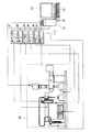
以下、図面を参照して本発明の実施の形態を説明する。図1は、本発明に係る分析装置を含む分析システムに係る図である。図1に示すように、本発明に係る分析システムは、分析装置26と、電装部113と、制御部(例えば、パーソナルコンピュータの本体)31とを含む。分析装置26の詳細は、図2に示す通りである。電装部113は、Z軸ドライバーコントローラー27と、Y軸ドライバーコントローラ28と、チップ先端位置センサーアンプ29と、X軸ドライバーコントローラ30と、試料台移送ドライバーコントローラー46と、顕微鏡ドライバーコントローラー47とを備えている。制御部31には、例えば、入力装置として、キーボード34、ポインティングデバイス32が接続され、出力装置としてディスプレイ33や図示しないプリンタなどが接続される。
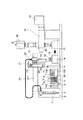
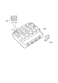
図2は、本発明に係る分析装置の全体図である。図2に記載の各部の説明は、動作の説明時に行うものとし、ここでは省略する。
Embodiments of the present invention will be described below with reference to the drawings. FIG. 1 is a diagram related to an analysis system including an analysis apparatus according to the present invention. As shown in FIG. 1, the analysis system according to the present invention includes an
FIG. 2 is an overall view of the analyzer according to the present invention. The description of each part illustrated in FIG. 2 is performed when the operation is described, and is omitted here.
まず、本発明の一実施形態に係る分析装置の動作を説明する前に。本発明の一実施形態に係る使い捨て試薬パックの構成を図3を参照して説明する。
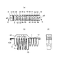
図3に示すように、本実施形態に係る試薬パック5は、試料容器8と、チップ6がセットされたチップ容器部48〜55と、所定の分析用の溶液7が充填された溶液収納部56〜63と、廃液容器部13と、試料前処理容器部64とが一体形成されている。また。溶液収納部56〜63の上部には、溶液の漏れ等を防止するための溶液収納部蓋フィルム42が設けられている。更に、試薬パック5の上部全体を覆うような試薬パックカバー43を設けることが好ましい。なお、図3において、(a)は上面図、(b)は(a)のA−A断面図、(c)は側面図である。また、図3の構成において、すべての容器を一体形成している必要はなく、少なくとも、チップ容器部48〜55と、溶液収納部56〜63と、廃液容器部13とを備えていれば良い。
なお、後述するように、試薬パック5を分析装置26にセットした後の分析は自動で行われるので、分析装置26への位置決めを正確に行うために、位置決め穴45が設けられている。更に、試薬パック5の種類や、充填されている試料の種類などを特定するための識別情報であるバーコードラベル44が試薬パック5に付されていることが好ましい。なお、このバーコードラベル44は可読文字を含み、バーコードリーダが無くともオペレータが読むことが出来ることが好ましい。更に、バーコードラベル44の情報として、試薬パックのロットナンバ−、使用期限、分析項目、分析手順識別コード等の情報が含まれていることが好ましい。なお、バーコードラベル44の代わりに、ICタグ等の所定の情報を識別できるような手段であればどのようなものを用いてもよい。
本発明の一実施形態に係る試薬パック5は、試薬となる溶液を含めて、必要な容器が一体形成されているので。簡単に分析や、分析後の後片付けを行うことができる。
First, before explaining the operation of the analyzer according to an embodiment of the present invention. A configuration of a disposable reagent pack according to an embodiment of the present invention will be described with reference to FIG.
As shown in FIG. 3, the
As will be described later, since the analysis after the
In the
以下、主に図2を参照して、本発明に係る分析装置の動作について説明する。なお、コンピュータ31を含む制御を除き、本発明の実施形態に係る装置はすべて装置ベース板上に配置されている。
The operation of the analyzer according to the present invention will be described below mainly with reference to FIG. Except for the control including the
(前準備)
1) コンピュータ31(モニター33を含む)、及び、分析装置26、電装部113の電源を入れ、システムの立ち上げ(コンピュータのOS起動、制御プログラム起動、分析装置のイニシャライズ等)を行う。
2) オペレータは予め決められた分析項目に対応している、試薬パック5と、DNA反応容器15を保冷庫から取り出す。このDNA反応容器15は、2体に分かれていて、試料槽16を挟み込んで固定している。
3) 1つもしくは複数の試薬パック5を分析装置26の試薬パック載置部108に、DNA反応容器15を試料台14にセットする。この際、装置カバー内又は、ゴミやホコリなどが試薬パック5内に入り込まない環境下で試薬パックカバー43、図示しないDNA反応容器15の蓋を取り外し、試薬パック種類に対応している試料を、試薬パックの試料容器部8に所定量分注する。なお、試薬パック5は、装置のX軸直動ロボット4上に設けられた試薬パック載置部108の位置決めピン105、106に、試薬パック5の位置決め穴が嵌合されて固定・位置決めされる。DNA反応容器15は、試料台14に固定・位置決めされる。
(Preparation)
1) The computer 31 (including the monitor 33), the
2) The operator takes out the
3) Set one or a plurality of
(装置動作開始)
4) オペレータが分析装置26の制御部31へ動作開始を指示する。これにより、以下の動作がコンピュータ(制御部)31により自動的に行われる。
5) 試薬パック載置部108が移動し、図示しないバーコードリーダで試薬パック5に取り付けられたバーコードラベル44の情報を読み取る。この読み取られた情報から試薬パック5の有効期限を確認すると共に、予め分析装置内にプログラムされている複数の動作手順のうち読み取られた試薬情報に基づいた動作手順を選択する。又、もし、コンピュータ31が通信手段(例えばインターネット等)で外部と通信可能であれば、外部(或いは上位)コンピュータへ試薬パック5のバーコードラベル44の情報を送ることで、最適かつ最新の分析装置の動作手順をダウンロードして、その動作手順によって分析装置26を動作させることもできる。更に、通信手段を使用して、分析結果の照合や解析を、外部(上位)コンピュータの情報を使って行うことも可能となる。
(Device operation started)
4) The operator instructs the
5) The reagent
(チップ装着)
6) Y軸直動ロボット107が動作することにより、Z軸直動ロボット21に搭載されているノズル20を試薬パック5上の未使用のチップ6上に移動する。同じく、X軸直動ロボット4も動作し、ノズル20を、所定の試薬パック5上の未使用のチップ6上に移動する。
なお、図3に示す試薬パック5には8本のチップが装着されているが、図3では、試薬パック5に装着可能な最大本数が8本であり、分析に使用するチップの本数に従って、チップの数を減らすことが可能である。その場合には、試薬パック5のチップ容器部48〜55にすべてチップを用意しておくのではなく、チップを入れていないチップ容器部があっても良い。また、チップ6が9本以上必要な場合には、例えば試薬パック5を2列構成とすれば良い。なお、チップ6の数が増えるに従って、3列構成、4列構成としても良い。同様に、溶液収納部56〜63も、チップ容器部48〜55と同様に、8ヶ所としているが、分析に必要な溶液の種類に応じて、溶液収納部56〜63に溶液の入っていない溶液収納部を設けてもよい。なお、1種類の溶液の使用量が、1つの溶液収納部の容量以上になるような場合は、複数の溶液収納部に同じ種類の溶液を入れることで対応できる。また、9種類以上の溶液を使用する場合は、チップの本数が増えた場合と同様に、試薬パック5を3列構成や、4列構成にすることで対応可能である。
7) タイミングプーリー23,24が回転することにより、タイミングベルト22が動作して、Z軸直動ロボット21が動作することにより、ノズル20が所定量降下し、チップ19(6)に押し込まれて、ノズル20とチップ19が嵌合する。
8) Z軸直動ロボット21が動作することにより、ノズル20と嵌合したチップ19が上点位置(原点センサー位置:すなわち、ノズル20の下降前の位置)まで上昇する(図4の(a)は上昇中の図)。
(Chip mounted)
6) When the Y-axis
Although eight chips are mounted on the
7) When the timing pulleys 23 and 24 are rotated, the
8) When the Z-axis
(試料吸引)
9) Y軸直動ロボット107が動作することにより、チップ19を試薬パック5内の所定の試料容器部8上に移動する。
10) Z軸直動ロボット21が動作することにより、チップ19が降下し、チップ19の先端を試料容器部8の底ぎりぎりに位置決めする。
11) 例えばテフロンチューブ製の通気管25を介して接続されたシリンジ2に接続されたシリンジポンプ1を駆動して、チップ19内に試料9(以下、「試薬」と称することもある)を吸引する。
12) 試料9の吸引完了後、Z軸直動ロボット21を動作させて、チップ19を上点位置まで上昇させる。
(Sample suction)
9) The
10) When the Z-axis
11) For example, the syringe pump 1 connected to the
12) After the suction of the
(試料前処理からチップの取り外し)
13) 試料9の前処理が必要ならば、以下の手順を実施する。なお、ここで、「試料の前処理」とは、試料濃度の希釈、試料改質剤(例えば界面活性剤など)の投入などの処理を意味する。
14) 吸引した試料を試薬パック5内の試料前処理容器部64へ吐出し、試料で汚れたチップを試薬パック5内の元の場所に廃棄し(この際、Z軸直動ロボットに取り付けられたチップ取り外しユニット12を駆動させ、チップ19の上縁を押すことでノズル20からチップを取り外す)、新しいチップ6(19)をノズル20に取り付ける(図4の(f))。
15) ノズル20に取り付けられた新しいチップ19を使い、試薬パック5の溶液収納部56〜63に入っている所定の溶液を吸引する(図4の(g))。この際、溶液収納部56〜63の溶液収納部蓋フィルム42にチップ先端で穴を空け、所定の高さまでチップを降下させ溶液を吸引する(ピアッシング吸引)。なお、溶液収納部蓋フィルム42はアルミニウム箔を主成分とし、溶液を変質させないためにポリプロピレン、ポリエチレン、ポリエステル、ポリオレフィンなどの樹脂コーティングを施したフィルム等の、容易にチップ19の先端で穿孔することができる素材のものを使用することが好ましい。また、試薬パック5そのものの材質を同様又は、溶着可能な樹脂としているため、溶液収納部蓋フィルム42と試薬パック5本体は超音波溶着等により、水漏れや、ゴミ・ホコリの混入が無いように、水密シールされている。
16) 試料9の吸引完了後に、チップ19を上昇させて、試料前処理容器部64の上部まで移動する。
17) Z軸直動ロボット21が動作することにより、チップ19が降下して、チップ19の先端が試料前処理容器部64の底ぎりぎりに位置決めされる。
18) チップ19内溶液を吐出し、事前に吐出した試料容量と今回吐出した溶液の合計容量の少なくとも1/2以上の容量(無論、上限は合計容量もしくはチップの最大容量の内、少ない方である)を吸引し、続いて吐出する。この吸引吐出を複数回(10回以上が望ましいが、試料、溶液の種類、量、撹拌程度等により回数、流速は変える必要がある)繰り返し、試料と溶液を撹拌する(図4の(b))。
19) 試料と溶液の撹拌が完了した後、同じチップ19を用いて所定量試料を吸引する。
20) 試料の吸引完了後、Z軸直動ロボット21を動作させて、チップを上点位置まで上昇させる。
(Removal of tip from sample pretreatment)
13) If
14) The aspirated sample is discharged to the
15) Using the
16) After the suction of the
17) When the Z-axis
18) Discharge the solution in the
19) After the stirring of the sample and the solution is completed, a predetermined amount of the sample is sucked using the
20) After completing the suction of the sample, the Z-axis
(溶液吐出)
21) Y軸直動ロボット107が動作することにより、試料を吸引した状態のチップ19をDNA反応容器15に設けられた試料槽16用穴部上に移動する。
22) Z軸直動ロボット21が動作することにより、チップをDNA反応容器15に設けられた試料槽16用穴の縁高さまで降下させる(図4の(c))。
23) シリンジポンプ1を駆動し、チップ19内の試料を、DNA反応容器15の試料槽16へ全量吐出する。
24) 吐出完了後、Z軸直動ロボット21を動作させ、チップ19を上点位置まで上昇させる。
(Solution discharge)
21) When the Y-axis linearly moving
22) When the Z-axis
23) The syringe pump 1 is driven, and the entire sample in the
24) After completion of the discharge, the Z-axis
(チップ取り外し)
25) 試料で汚れたチップ19を試薬パック5内の元の場所に廃棄する。
(Chip removal)
25) The
(溶液反応)
26) DNA反応容器15内に分注された試料は、図示されていないヒータによって50℃程度に保温されながら、図示されていない溶液駆動手段によって、試料槽16に固定されている図5に示すようなDNAプローブとハイブリダイゼーション反応を開始する。図5は反応容器の一例を示す図である。図5において、反応容器109は、DNA反応容器試料槽111(「試料槽」と称する)が設けられており、試料槽111の内部にはDNAプローブ112が設けられている。なお、DNAマイクロアレイ112の円状のスポットがDNAプローブである。また、符号110は試料槽111用の蓋である。なお、ハイブリダイゼーション反応は数分から数時間の反応時間を必要とする。
(Solution reaction)
26) The sample dispensed in the
(チップ装着及び、チップ先端位置計測)
27) 試薬パック5内の新しいチップ6をノズル20に取り付ける(図4の(f))。そして、Y軸直動ロボット107が動作することにより、新しいチップが装着されたノズル20を、チップ先端位置センサー保持板10に取り付けられたチップ先端位置センサー11位置へ移動し、チップ19の先端位置を測定する。なお、チップ19の先端位置の測定は、本発明の課題とは無関係であるので、詳細な測定方法などについては省略し、以下、チップ19の先端位置が正確に測定できたものとして説明を行う。
(Chip mounting and tip tip position measurement)
27) A
28) Z軸直動ロボット21が動作することにより、チップ19が上点位置まで上昇する。
28) When the Z-axis
(廃液吸引)
29) 工程26)から開始したハイブリダイゼーション反応を終了させる。なお、反応時間は、当該ハイブリダイゼーション反応に必要充分な時間である。
30) Y軸直動ロボット107が動作することにより、チップ先端位置センサー11による先端位置測定後のチップ19が、DNA反応容器15に設けられた試料槽用穴部縁近傍に移動する(図4の(c))。
31) Z軸直動ロボット21が動作することにより、先端位置測定後のチップ19がDNA反応容器15に設けられた試料槽16の表面から0.1mm程度の間隔をあけた高さまで降下する(図4の(d))。
32) シリンジポンプ1を動作させて、試料槽16上の溶液17を吸引する。
33) Z軸直動ロボット21が動作することにより、溶液を吸引したノズル20が上点位置まで上昇する。
(Waste liquid suction)
29) Terminate the hybridization reaction started from step 26). The reaction time is a sufficient time necessary for the hybridization reaction.
30) When the Y-axis
31) When the Z-axis
32) The syringe pump 1 is operated to suck the solution 17 on the
33) When the Z-axis
(廃液、チップ取り外し、取り付け)
34) Y軸直動ロボット107が動作することにより、チップ19が試薬パック5上に配置された廃液容器部13の上部へ移動する。
35) Z軸直動ロボット21が動作することにより、チップ19の先端が廃液容器部上面の下、少なくとも5mm以上下まで降下する。
36) シリンジポンプ1を動作させ、チップ19内の溶液を廃液容器部13内に吐出する。ここで、溶液の吐出量は吸引した全量とする(図4の(e))。
37) 廃液で汚れたチップを試薬パック5内の元の場所に廃棄する。この際、Z軸直動ロボットに取り付けられたチップ取り外しユニット12を駆動して、チップ19の上縁(ノズル20との嵌合部)を下方に押すことでノズル20からチップを取り外す。そして、新しいチップ6(19)をノズル20に取り付ける(図4の(f))。
(Waste liquid, chip removal, installation)
34) When the Y-axis linearly moving
35) When the Z-axis
36) The syringe pump 1 is operated to discharge the solution in the
37) Discard the chip contaminated with the waste liquid in the original place in the
(洗浄)
38) 試薬パック5にセットされている溶液(洗浄バッファ)を(溶液吸引)し、(溶液吐出)、図示されていない溶液駆動手段によって溶液駆動による洗浄、(チップ取り外し)、(チップ装着及び、チップ先端位置計測)、(廃液吸引)、(廃液、チップ取り外し、取り付け)の各工程を行うことで、ハイブリダイゼーション反応後の洗浄を行う。なお、洗浄作業は、数種類の溶液(洗浄バッファ)を取り替えながら数回行うこともできる。又、同じ溶液(洗浄バッファ)を使って数回繰り返すこともできる。
(Washing)
38) The solution (washing buffer) set in the
(測光)
39) DNA反応容器15を試料台移送用直動ロボット41により顕微鏡の対物レンズ40の下に、試料台移送用直動ロボット41で移動し、ハイブリダイゼーション結果を光学的に測定する。例えば、蛍光観察の場合には、光源38から出射された励起光を試料槽16の内部にあるDNAプローブとハイブリダイゼーションした試料DNAに、顕微鏡透光管18を介して照射し、発生した蛍光をCCDカメラ39で撮像することにより、ハイブリダイゼーション結果を測定する。
なお、分析装置の26の制御部31による自動動作はここまでである。
(Photometry)
39) The
In addition, the automatic operation | movement by the
(後処理)
40) オペータは分析装置26にセットされている試薬パック5、DNA反応容器15を取り外す。
(Post-processing)
40) The operator removes the
41) 取り外した試薬パック5、DNA反応容器15は地方自治体などが定めている処理方法に従って廃棄物処理を行い廃棄する。
42) 分析装置の作業後イニシャライズ等を行い、コンピュータ31(モニター33を含む)、及び、分析装置26、電装部113の電源を切る。
43) 尚、得られた画像データなどは、別のコンピュータを用いて解析する事もできる。又、試薬パック5に取り付けられたバーコードラベルの情報と共に、画像データをインターネット等を用いて上位コンピュータに送り、データ解析サービス、遺伝子情報照合サービス等を利用し解析処理を行うこともできる。
41) The removed
42) The
43) The obtained image data and the like can be analyzed using another computer. Also, together with the information on the barcode label attached to the
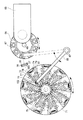
上記の実施形態では、X−Y−Z軸直線動作型分析装置及び、その分析装置に適用可能な試薬パックについて説明したが、下記のような、回転動作型分析装置にも適用可能である。直線動作型分析装置は、停止位置の自由度が高く汎用ロボットを使用して構築できる特徴があるが、構成部品が多く、比較的大きくなってしまう。又、動作速度を速くしにくい事も知られている。それに対し、回転動作型分析装置(図6)は、停止位置自由度はかなり限定されてしまい、且つ汎用ロボットは見あたらないが、構成部品を少なくでき、小型化が可能である。又、動作速度を早くしやすい事も知られている。 In the above embodiment, the XYZ axis linear motion analyzer and the reagent pack applicable to the analyzer have been described. However, the present invention can also be applied to a rotational motion analyzer as described below. The linear motion analysis apparatus has a feature that it can be constructed using a general-purpose robot with a high degree of freedom of a stop position, but it has many components and becomes relatively large. It is also known that it is difficult to increase the operation speed. On the other hand, the rotational motion type analyzer (FIG. 6) has a considerably limited degree of freedom in stopping position, and no general-purpose robot can be found, but the number of components can be reduced and the size can be reduced. It is also known that the operation speed can be easily increased.
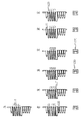
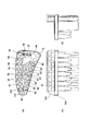
図6は、本発明の他の実施形態に係る回転動作型分析装置の概略構成を示す図である。また、図7は、同装置に適用可能な使い捨て試薬パック104の概略構成を示す図である。
FIG. 6 is a diagram showing a schematic configuration of a rotational motion analyzer according to another embodiment of the present invention. FIG. 7 is a diagram showing a schematic configuration of a
回転動作型分析装置では、ノズル移送用アーム回転軸87を回転中心とするノズル移送用アーム68の回転動作により試薬パックホイール71とインキュベータ含むDNA反応容器ホィール66との間の試料(試薬)の移動を行っている。このため、本実施形態に係る試薬パック104の各容器部の配置がノズル移送用アーム68の回転半径に合わせた位置に配置されている。まず。図7を参照して、試薬パック104の概略構成を説明する。
In the rotary operation type analyzer, the movement of the sample (reagent) between the reagent pack wheel 71 and the DNA
図7に示すように、本実施形態に係る試薬パック104は、試料容器79と、チップがセットされたチップ容器78、81〜86、101と、所定の分析用の溶液が充填された溶液収納部80、88〜91、93、94、99と、廃液容器部95と、試料前処理容器部96とが一体形成されている。また。溶液収納部80、88〜91、93、94、99の上部には、溶液の漏れ等を防止するための溶液収納部蓋フィルム92が設けられている。更に、試薬パック104の上部全体を覆うような試薬パックカバー100を設けることが好ましい。なお、図7において、(a)は上面図、(b)は正面図、(c)は側面図である。また、図7の構成において、すべての容器を一体形成している必要はなく、少なくとも、チップ容器78、81〜86、101と、溶液収納部80、88〜91、93、94、99と、廃液容器部95とを備えていれば良いことは上記の実施形態と同様である。また、上記の実施形態と同様に、試薬パック104を分析装置にセットした後の分析は自動で行われるので、分析装置への位置決めを正確に行うために、位置決め穴又は/及び切り欠き98が設けられている。更に、試薬パック104の種類や、充填されている試料の種類などを特定するための識別情報であるバーコードラベル97が試薬パック5に付されていることが好ましい。
As shown in FIG. 7, the
上記のような試薬パックが適用される回転動作型分析装置の概略構成を図6を参照して説明する。なお、回転動作型分析装置(以下、「分析装置」と称する)の動作は上記の実施形態と同様であるので、説明を省略する。 A schematic configuration of a rotational motion analyzer to which the reagent pack as described above is applied will be described with reference to FIG. Note that the operation of the rotational motion type analyzer (hereinafter referred to as “analyzer”) is the same as that of the above embodiment, and thus the description thereof is omitted.
分析装置の位置決めピン74及び102と試薬パック104の位置決め穴98とを嵌合させて、試薬パック支持台77上に試薬パック73(104)を設置する。分析装置の試薬パックホイール71は、試薬パックホィール回転軸75を回転軸として回転可能になっている。ノズル移送用アーム68の先端に設けられたノズル72が、図示しない上下駆動部によって下降して、チップ78に嵌合され、取り付けられる。チップ78が取り付けられたノズル72が上昇して上点位置まで達すると、ノズル移送用アーム68が回転して、チップ先端位置センサーユニット52でその先端位置が検出される。ここで、チップ先端位置センサーユニット52は、光電センサー発光部36と、光電センサー受光部37とからなり、チップ72の先端がセンサー光35で検出される。なお、チップ先端位置センサーユニット52は、光電センサー以外に、その先端が検出可能であれば、どのようなものを使用しても良い。チップ先端位置センサーユニット52で先端が検出されたチップ78は、ノズル移送用アーム68が更に回転することによって、DNA反応容器67上に位置される。DNA反応容器67が搭載されたDNA反応容器ホイール66は、DNA反応容器ホィール回転軸69を中心として回転可能になっており、所望のDNA反応容器67を顕微鏡65の図示しない対物レンズの下に位置させることで、光学測定が可能になっている
以上述べたように、本発明の実施形態によれば、ユーザは分析装置に、試薬パックと、反応容器をセットするのみで、分析結果を得ることができる。更に、分析後の後片づけも試薬パックと反応容器の廃棄だけになるので、極めて取り扱いや操作が簡単である。
The reagent pack 73 (104) is placed on the reagent pack support 77 by fitting the positioning pins 74 and 102 of the analyzer and the
多種類の試薬、洗浄液、チップ、サンプルカップ等を1分析毎にまとめ、パック化することで煩雑な薬品や消耗品の管理を削減することが出来る。更に、溶液種類や濃度が予めセットされているので、間違いは発生しなくなる。更に、バーコード情報(バーコード以外のコンピュータなどで読み取り可能な情報を含む)による操作の自動化により、オペレータの負担が軽減すると共に、入力ミス等による操作の間違いもなくなる。また、バーコード情報により、検査種別などを表示などにより確認できるようにすることで、更に間違いを防止できる。 By collecting various types of reagents, cleaning solutions, chips, sample cups, etc. for each analysis and packaging them, management of complicated chemicals and consumables can be reduced. Further, since the solution type and concentration are set in advance, no error occurs. Furthermore, automation of operations using barcode information (including information that can be read by a computer other than barcodes) reduces the burden on the operator and eliminates erroneous operations due to input errors. Further, by making it possible to confirm the inspection type by displaying the barcode information, it is possible to further prevent mistakes.
試薬パックと反応容器を1セットとすることにより、分析に関わる全消耗品を1パッケージ化できる。その為、消耗品の供給元を1つに出来、品質管理や製造責任を一元化できる。また、供給者は、分析装置を含めた全消耗品供給を一括して管理できるため品質管理が容易となる。更に、消耗品が1つのセットになっているので、分析装置の小型化、低価格化が実現しやすくなる。 By using one set of reagent pack and reaction container, all consumables related to analysis can be packaged in one package. Therefore, the supply source of consumables can be unified, and quality control and manufacturing responsibility can be unified. In addition, since the supplier can collectively manage the supply of all consumables including the analyzer, quality control is facilitated. Furthermore, since the consumables are in one set, it is easy to realize a reduction in size and cost of the analyzer.
以上の実施形態では、DNAを検出する場合を例にとって説明したが、蛋白、抗原抗体、その他生化学反応を検出する場合にも適用可能である。 In the above embodiment, the case of detecting DNA has been described as an example. However, the present invention can also be applied to the case of detecting protein, antigen antibody, and other biochemical reactions.
本発明は、上記各実施の形態に限ることなく、その他、実施段階ではその要旨を逸脱しない範囲で種々の変形を実施し得ることが可能である。さらに、上記各実施形態には、種々の段階の発明が含まれており、開示される複数の構成要件における適宜な組合せにより種々の発明が抽出され得る。 The present invention is not limited to the above-described embodiments, and various modifications can be made without departing from the scope of the invention at the stage of implementation. Further, the above embodiments include inventions at various stages, and various inventions can be extracted by appropriately combining a plurality of disclosed constituent elements.
また、例えば各実施形態に示される全構成要件から幾つかの構成要件が削除されても、発明が解決しようとする課題の欄で述べた課題が解決でき、発明の効果で述べられている効果が得られる場合には、この構成要件が削除された構成が発明として抽出され得る。 In addition, for example, even if some structural requirements are deleted from all the structural requirements shown in each embodiment, the problem described in the column of the problem to be solved by the invention can be solved, and the effect described in the effect of the invention Can be obtained as an invention.
1…シリンジポンプ、2…シリンジ、4…X軸直動ロボット、5…試薬パック、6…チップ、7…溶液、8…試料容器部、9…試料、10…チップ先端位置センサー保持板、11…チップ先端位置センサー、12…チップ取り外しユニット、13…廃液容器部、14…試料台、15…DNA反応容器、16…試料槽、17…溶液(試料)、18…顕微鏡透光管、19…チップ、20…ノズル、21…Z軸直動ロボット、22…タイミングベルト、23、24…タイミングプーリー、25…通気管、26…分析装置、27…Z軸ドライバーコントローラー、28…Y軸ドライバーコントローラ、29…チップ先端位置センサーアンプ、30…X軸ドライバーコントローラ、31…コンピュータ(制御部)、32…ポインティングデバイス、33…ディスプレイ、34…キーボード、35…センサー光、36…光電センサー発光部、37…光電センサー受光部、38…光源、39…CCDカメラ、40…対物レンズ、41…試料台移送用直動ロボット、42…溶液収納部蓋フィルム、43…試薬パックカバー、44…バーコードラベル、45…位置決め穴、46…試料台移送ドライバーコントローラー、47…顕微鏡ドライバーコントローラー、48〜55…チップ容器部、56〜63…溶液収納部、64…試料前処理容器部、65…顕微鏡、66…DNA反応容器ホイール、67…DNA反応容器、68…ノズル移送用アーム、69…DNA反応容器ホィール回転軸、71…試薬パックホイール、72…ノズル、73…試薬パック、74…位置決めピン、75…試薬パックホィール回転軸、77…試薬パック支持台、79…試料容器、78、81〜86、101…チップ容器部、87…ノズル移送用アーム回転軸、80、88〜91、93、94、99…溶液収納部、92…溶液収納部蓋フィルム、95…廃液容器部、96…試料前処理容器部、97…バーコードラベル、98…位置決め穴及び/又は切り欠き、100…試薬パックカバー、104…試薬パック、105、106…位置決めピン、107…Y軸直動ロボット、108…試薬パック載置部、109…反応容器、111…DNA反応容器試料槽、112…DNAプローブ、113…電装部、300…チップ先端位置センサーユニット。 DESCRIPTION OF SYMBOLS 1 ... Syringe pump, 2 ... Syringe, 4 ... X-axis direct-acting robot, 5 ... Reagent pack, 6 ... Chip, 7 ... Solution, 8 ... Sample container part, 9 ... Sample, 10 ... Chip tip position sensor holding plate, 11 DESCRIPTION OF SYMBOLS ... Tip position sensor, 12 ... Chip removal unit, 13 ... Waste liquid container part, 14 ... Sample stand, 15 ... DNA reaction container, 16 ... Sample tank, 17 ... Solution (sample), 18 ... Microscope translucent tube, 19 ... Chip, 20 ... Nozzle, 21 ... Z-axis linear motion robot, 22 ... Timing belt, 23, 24 ... Timing pulley, 25 ... Vent pipe, 26 ... Analyzer, 27 ... Z-axis driver controller, 28 ... Y-axis driver controller, 29 ... Chip tip position sensor amplifier, 30 ... X-axis driver controller, 31 ... Computer (control unit), 32 ... Pointing device, 33 Display, 34 ... Keyboard, 35 ... Sensor light, 36 ... Photoelectric sensor light emitting unit, 37 ... Photoelectric sensor light receiving unit, 38 ... Light source, 39 ... CCD camera, 40 ... Objective lens, 41 ... Direct acting robot for transferring sample stage, 42 ... Liquid storage part cover film, 43 ... Reagent pack cover, 44 ... Bar code label, 45 ... Positioning hole, 46 ... Sample stage transfer driver controller, 47 ... Microscope driver controller, 48 to 55 ... Chip container part, 56 to 63 ... Solution storage section, 64 ... Sample pretreatment container section, 65 ... Microscope, 66 ... DNA reaction container wheel, 67 ... DNA reaction container, 68 ... Nozzle transfer arm, 69 ... DNA reaction container wheel rotating shaft, 71 ... Reagent pack wheel 72 ... Nozzle, 73 ... Reagent pack, 74 ... Positioning pin, 75 ... Reagent pack wheel times Shaft, 77 ... Reagent pack support, 79 ... Sample container, 78, 81 to 86, 101 ... Chip container part, 87 ... Nozzle transfer arm rotation shaft, 80, 88 to 91, 93, 94, 99 ... Solution storage part 92 ... Solution storage part cover film, 95 ... Waste liquid container part, 96 ... Sample pretreatment container part, 97 ... Barcode label, 98 ... Positioning hole and / or notch, 100 ... Reagent pack cover, 104 ... Reagent pack, 105, 106: positioning pins, 107: Y-axis linear motion robot, 108: reagent pack placement unit, 109 ... reaction vessel, 111 ... DNA reaction vessel sample tank, 112 ... DNA probe, 113 ... electrical component, 300 ... tip of tip Position sensor unit.
Claims (8)
前記試薬パックを用いて試料を分析した結果を分析する分析部とを備えたことを特徴とする分析装置。 A reagent pack placement unit capable of placing the disposable reagent pack according to any one of claims 1 to 7,
And an analyzer for analyzing the result of analyzing the sample using the reagent pack.
Priority Applications (1)
| Application Number | Priority Date | Filing Date | Title |
|---|---|---|---|
| JP2004108188A JP2005291954A (en) | 2004-03-31 | 2004-03-31 | Disposable reagent pack and analyzer using the reagent pack |
Applications Claiming Priority (1)
| Application Number | Priority Date | Filing Date | Title |
|---|---|---|---|
| JP2004108188A JP2005291954A (en) | 2004-03-31 | 2004-03-31 | Disposable reagent pack and analyzer using the reagent pack |
Publications (1)
| Publication Number | Publication Date |
|---|---|
| JP2005291954A true JP2005291954A (en) | 2005-10-20 |
Family
ID=35325039
Family Applications (1)
| Application Number | Title | Priority Date | Filing Date |
|---|---|---|---|
| JP2004108188A Pending JP2005291954A (en) | 2004-03-31 | 2004-03-31 | Disposable reagent pack and analyzer using the reagent pack |
Country Status (1)
| Country | Link |
|---|---|
| JP (1) | JP2005291954A (en) |
Cited By (69)
| Publication number | Priority date | Publication date | Assignee | Title |
|---|---|---|---|---|
| JP2007218874A (en) * | 2006-02-20 | 2007-08-30 | Shimadzu Corp | Reaction kit |
| WO2007097229A1 (en) * | 2006-02-20 | 2007-08-30 | Shimadzu Corporation | Reaction kit |
| JP2007253118A (en) * | 2006-03-24 | 2007-10-04 | Fujifilm Corp | Pipette tip storage |
| JP2007275005A (en) * | 2006-04-10 | 2007-10-25 | Shimadzu Corp | Reaction vessel, reaction vessel processing device and diagnostic device |
| JP2007285834A (en) * | 2006-04-17 | 2007-11-01 | Shimadzu Corp | Reaction vessel |
| WO2007132740A1 (en) * | 2006-05-11 | 2007-11-22 | Shimadzu Corporation | Reaction container kit |
| JP2007315871A (en) * | 2006-05-24 | 2007-12-06 | Olympus Corp | Autoanalyzer |
| WO2007139056A1 (en) * | 2006-06-01 | 2007-12-06 | Shimadzu Corporation | Dispensing tip, reaction kit using the same, and dispensing tip drive mechanism |
| JP2007322290A (en) * | 2006-06-01 | 2007-12-13 | Shimadzu Corp | Reaction kit |
| JP2007319097A (en) * | 2006-06-01 | 2007-12-13 | Shimadzu Corp | Reaction kit |
| JP2008014638A (en) * | 2006-06-30 | 2008-01-24 | Sakae:Kk | Autoanalyzer |
| JP2010533490A (en) * | 2007-07-13 | 2010-10-28 | ハンディーラブ インコーポレイテッド | Integrated device for nucleic acid extraction and diagnostic testing on multiple biological samples |
| JP2010540971A (en) * | 2007-10-02 | 2010-12-24 | セラノス, インコーポレイテッド | Modular point-of-care device and use thereof |
| JP2011501132A (en) * | 2007-10-10 | 2011-01-06 | ポカード・ディアグノスティクス・リミテッド | System for identifying bacteria in urine |
| WO2012036296A1 (en) * | 2010-09-17 | 2012-03-22 | ユニバーサル・バイオ・リサーチ株式会社 | Cartridge and automatic analysis device |
| US8415103B2 (en) | 2007-07-13 | 2013-04-09 | Handylab, Inc. | Microfluidic cartridge |
| US8420015B2 (en) | 2001-03-28 | 2013-04-16 | Handylab, Inc. | Systems and methods for thermal actuation of microfluidic devices |
| US8440149B2 (en) | 2001-02-14 | 2013-05-14 | Handylab, Inc. | Heat-reduction methods and systems related to microfluidic devices |
| US8473104B2 (en) | 2001-03-28 | 2013-06-25 | Handylab, Inc. | Methods and systems for control of microfluidic devices |
| US8470586B2 (en) | 2004-05-03 | 2013-06-25 | Handylab, Inc. | Processing polynucleotide-containing samples |
| US8475739B2 (en) | 2011-09-25 | 2013-07-02 | Theranos, Inc. | Systems and methods for fluid handling |
| USD692162S1 (en) | 2011-09-30 | 2013-10-22 | Becton, Dickinson And Company | Single piece reagent holder |
| US8617905B2 (en) | 1995-09-15 | 2013-12-31 | The Regents Of The University Of Michigan | Thermal microvalves |
| CN103543282A (en) * | 2010-07-23 | 2014-01-29 | 贝克曼考尔特公司 | System for processing samples |
| US8679831B2 (en) | 2003-07-31 | 2014-03-25 | Handylab, Inc. | Processing particle-containing samples |
| US8685341B2 (en) | 2001-09-12 | 2014-04-01 | Handylab, Inc. | Microfluidic devices having a reduced number of input and output connections |
| US8703069B2 (en) | 2001-03-28 | 2014-04-22 | Handylab, Inc. | Moving microdroplets in a microfluidic device |
| US8710211B2 (en) | 2007-07-13 | 2014-04-29 | Handylab, Inc. | Polynucleotide capture materials, and methods of using same |
| US8709787B2 (en) | 2006-11-14 | 2014-04-29 | Handylab, Inc. | Microfluidic cartridge and method of using same |
| CN103959070A (en) * | 2011-09-30 | 2014-07-30 | 贝克顿·迪金森公司 | Combination reagent strips |
| US8840838B2 (en) | 2011-09-25 | 2014-09-23 | Theranos, Inc. | Centrifuge configurations |
| US8852862B2 (en) | 2004-05-03 | 2014-10-07 | Handylab, Inc. | Method for processing polynucleotide-containing samples |
| US8883490B2 (en) | 2006-03-24 | 2014-11-11 | Handylab, Inc. | Fluorescence detector for microfluidic diagnostic system |
| US8895311B1 (en) | 2001-03-28 | 2014-11-25 | Handylab, Inc. | Methods and systems for control of general purpose microfluidic devices |
| US9040288B2 (en) | 2006-03-24 | 2015-05-26 | Handylab, Inc. | Integrated system for processing microfluidic samples, and method of using the same |
| US9186677B2 (en) | 2007-07-13 | 2015-11-17 | Handylab, Inc. | Integrated apparatus for performing nucleic acid extraction and diagnostic testing on multiple biological samples |
| WO2015192329A1 (en) * | 2014-06-17 | 2015-12-23 | 深圳迈瑞生物医疗电子股份有限公司 | Nucleic acid extractor waste liquid container, nucleic acid extractor, and control method |
| US9250229B2 (en) | 2011-09-25 | 2016-02-02 | Theranos, Inc. | Systems and methods for multi-analysis |
| US9259734B2 (en) | 2007-07-13 | 2016-02-16 | Handylab, Inc. | Integrated apparatus for performing nucleic acid extraction and diagnostic testing on multiple biological samples |
| US9268915B2 (en) | 2011-09-25 | 2016-02-23 | Theranos, Inc. | Systems and methods for diagnosis or treatment |
| US9347586B2 (en) | 2007-07-13 | 2016-05-24 | Handylab, Inc. | Automated pipetting apparatus having a combined liquid pump and pipette head system |
| CN105940094A (en) * | 2014-06-17 | 2016-09-14 | 深圳迈瑞生物医疗电子股份有限公司 | Nucleic acid extraction apparatus and method of operation thereof |
| US9464981B2 (en) | 2011-01-21 | 2016-10-11 | Theranos, Inc. | Systems and methods for sample use maximization |
| US9506866B2 (en) | 2008-02-05 | 2016-11-29 | Pocared Diagnostics Ltd. | System for conducting the identification of bacteria in biological samples |
| US9618139B2 (en) | 2007-07-13 | 2017-04-11 | Handylab, Inc. | Integrated heater and magnetic separator |
| US9619627B2 (en) | 2011-09-25 | 2017-04-11 | Theranos, Inc. | Systems and methods for collecting and transmitting assay results |
| US9632102B2 (en) | 2011-09-25 | 2017-04-25 | Theranos, Inc. | Systems and methods for multi-purpose analysis |
| US9645143B2 (en) | 2011-09-25 | 2017-05-09 | Theranos, Inc. | Systems and methods for multi-analysis |
| USD787087S1 (en) | 2008-07-14 | 2017-05-16 | Handylab, Inc. | Housing |
| US9664702B2 (en) | 2011-09-25 | 2017-05-30 | Theranos, Inc. | Fluid handling apparatus and configurations |
| US9765389B2 (en) | 2011-04-15 | 2017-09-19 | Becton, Dickinson And Company | Scanning real-time microfluidic thermocycler and methods for synchronized thermocycling and scanning optical detection |
| CN108196081A (en) * | 2018-01-23 | 2018-06-22 | 深圳市国赛生物技术有限公司 | A kind of POCT specific proteins analysis system |
| US10012664B2 (en) | 2011-09-25 | 2018-07-03 | Theranos Ip Company, Llc | Systems and methods for fluid and component handling |
| US10179910B2 (en) | 2007-07-13 | 2019-01-15 | Handylab, Inc. | Rack for sample tubes and reagent holders |
| US10288632B2 (en) | 2009-09-21 | 2019-05-14 | Pocared Diagnostics Ltd. | System for conducting the identification of bacteria in biological samples |
| CN111562286A (en) * | 2020-06-04 | 2020-08-21 | 深圳中科优瑞医疗科技有限公司 | Integrated reagent bag |
| US10761030B2 (en) | 2005-05-09 | 2020-09-01 | Labrador Diagnostics Llc | System and methods for analyte detection |
| US10822644B2 (en) | 2012-02-03 | 2020-11-03 | Becton, Dickinson And Company | External files for distribution of molecular diagnostic tests and determination of compatibility between tests |
| US10900066B2 (en) | 2006-03-24 | 2021-01-26 | Handylab, Inc. | Microfluidic system for amplifying and detecting polynucleotides in parallel |
| US11139084B2 (en) | 2009-10-19 | 2021-10-05 | Labrador Diagnostics Llc | Integrated health data capture and analysis system |
| US11162936B2 (en) | 2011-09-13 | 2021-11-02 | Labrador Diagnostics Llc | Systems and methods for multi-analysis |
| US11162947B2 (en) | 2006-05-10 | 2021-11-02 | Labrador Diagnostics Llc | Real-time detection of influenza virus |
| US11215610B2 (en) | 2006-10-13 | 2022-01-04 | Labrador Diagnostics Llc | Reducing optical interference in a fluidic device |
| US11287421B2 (en) | 2006-03-24 | 2022-03-29 | Labrador Diagnostics Llc | Systems and methods of sample processing and fluid control in a fluidic system |
| US11453906B2 (en) | 2011-11-04 | 2022-09-27 | Handylab, Inc. | Multiplexed diagnostic detection apparatus and methods |
| US11754554B2 (en) | 2007-08-06 | 2023-09-12 | Labrador Diagnostics Llc | Systems and methods of fluidic sample processing |
| US11802882B2 (en) | 2006-11-14 | 2023-10-31 | Labrador Diagnostics Llc | Methods for the detection of analytes in small-volume blood samples |
| US11806718B2 (en) | 2006-03-24 | 2023-11-07 | Handylab, Inc. | Fluorescence detector for microfluidic diagnostic system |
| WO2026018703A1 (en) * | 2024-07-19 | 2026-01-22 | 株式会社堀場製作所 | Analysis system, information processing system, control device, and computer program |
-
2004
- 2004-03-31 JP JP2004108188A patent/JP2005291954A/en active Pending
Cited By (216)
| Publication number | Priority date | Publication date | Assignee | Title |
|---|---|---|---|---|
| US8617905B2 (en) | 1995-09-15 | 2013-12-31 | The Regents Of The University Of Michigan | Thermal microvalves |
| US9528142B2 (en) | 2001-02-14 | 2016-12-27 | Handylab, Inc. | Heat-reduction methods and systems related to microfluidic devices |
| US8734733B2 (en) | 2001-02-14 | 2014-05-27 | Handylab, Inc. | Heat-reduction methods and systems related to microfluidic devices |
| US9051604B2 (en) | 2001-02-14 | 2015-06-09 | Handylab, Inc. | Heat-reduction methods and systems related to microfluidic devices |
| US8440149B2 (en) | 2001-02-14 | 2013-05-14 | Handylab, Inc. | Heat-reduction methods and systems related to microfluidic devices |
| US10619191B2 (en) | 2001-03-28 | 2020-04-14 | Handylab, Inc. | Systems and methods for thermal actuation of microfluidic devices |
| US8420015B2 (en) | 2001-03-28 | 2013-04-16 | Handylab, Inc. | Systems and methods for thermal actuation of microfluidic devices |
| US10571935B2 (en) | 2001-03-28 | 2020-02-25 | Handylab, Inc. | Methods and systems for control of general purpose microfluidic devices |
| US8894947B2 (en) | 2001-03-28 | 2014-11-25 | Handylab, Inc. | Systems and methods for thermal actuation of microfluidic devices |
| US8768517B2 (en) | 2001-03-28 | 2014-07-01 | Handylab, Inc. | Methods and systems for control of microfluidic devices |
| US9677121B2 (en) | 2001-03-28 | 2017-06-13 | Handylab, Inc. | Systems and methods for thermal actuation of microfluidic devices |
| US8895311B1 (en) | 2001-03-28 | 2014-11-25 | Handylab, Inc. | Methods and systems for control of general purpose microfluidic devices |
| US10351901B2 (en) | 2001-03-28 | 2019-07-16 | Handylab, Inc. | Systems and methods for thermal actuation of microfluidic devices |
| US9259735B2 (en) | 2001-03-28 | 2016-02-16 | Handylab, Inc. | Methods and systems for control of microfluidic devices |
| US8473104B2 (en) | 2001-03-28 | 2013-06-25 | Handylab, Inc. | Methods and systems for control of microfluidic devices |
| US8703069B2 (en) | 2001-03-28 | 2014-04-22 | Handylab, Inc. | Moving microdroplets in a microfluidic device |
| US8685341B2 (en) | 2001-09-12 | 2014-04-01 | Handylab, Inc. | Microfluidic devices having a reduced number of input and output connections |
| US9028773B2 (en) | 2001-09-12 | 2015-05-12 | Handylab, Inc. | Microfluidic devices having a reduced number of input and output connections |
| US10731201B2 (en) | 2003-07-31 | 2020-08-04 | Handylab, Inc. | Processing particle-containing samples |
| US11078523B2 (en) | 2003-07-31 | 2021-08-03 | Handylab, Inc. | Processing particle-containing samples |
| US12139745B2 (en) | 2003-07-31 | 2024-11-12 | Handylab, Inc. | Processing particle-containing samples |
| US10865437B2 (en) | 2003-07-31 | 2020-12-15 | Handylab, Inc. | Processing particle-containing samples |
| US9670528B2 (en) | 2003-07-31 | 2017-06-06 | Handylab, Inc. | Processing particle-containing samples |
| US8679831B2 (en) | 2003-07-31 | 2014-03-25 | Handylab, Inc. | Processing particle-containing samples |
| US10364456B2 (en) | 2004-05-03 | 2019-07-30 | Handylab, Inc. | Method for processing polynucleotide-containing samples |
| US8852862B2 (en) | 2004-05-03 | 2014-10-07 | Handylab, Inc. | Method for processing polynucleotide-containing samples |
| US8470586B2 (en) | 2004-05-03 | 2013-06-25 | Handylab, Inc. | Processing polynucleotide-containing samples |
| US10443088B1 (en) | 2004-05-03 | 2019-10-15 | Handylab, Inc. | Method for processing polynucleotide-containing samples |
| US10494663B1 (en) | 2004-05-03 | 2019-12-03 | Handylab, Inc. | Method for processing polynucleotide-containing samples |
| US11441171B2 (en) | 2004-05-03 | 2022-09-13 | Handylab, Inc. | Method for processing polynucleotide-containing samples |
| US10604788B2 (en) | 2004-05-03 | 2020-03-31 | Handylab, Inc. | System for processing polynucleotide-containing samples |
| US10761030B2 (en) | 2005-05-09 | 2020-09-01 | Labrador Diagnostics Llc | System and methods for analyte detection |
| US10908093B2 (en) | 2005-05-09 | 2021-02-02 | Labrador Diagnostics, LLC | Calibration of fluidic devices |
| US11630069B2 (en) | 2005-05-09 | 2023-04-18 | Labrador Diagnostics Llc | Fluidic medical devices and uses thereof |
| JP2007218874A (en) * | 2006-02-20 | 2007-08-30 | Shimadzu Corp | Reaction kit |
| US8257966B2 (en) | 2006-02-20 | 2012-09-04 | Shimadzu Corporation | Reaction kit |
| WO2007097229A1 (en) * | 2006-02-20 | 2007-08-30 | Shimadzu Corporation | Reaction kit |
| US9040288B2 (en) | 2006-03-24 | 2015-05-26 | Handylab, Inc. | Integrated system for processing microfluidic samples, and method of using the same |
| US10843188B2 (en) | 2006-03-24 | 2020-11-24 | Handylab, Inc. | Integrated system for processing microfluidic samples, and method of using the same |
| US11806718B2 (en) | 2006-03-24 | 2023-11-07 | Handylab, Inc. | Fluorescence detector for microfluidic diagnostic system |
| US12162007B2 (en) | 2006-03-24 | 2024-12-10 | Handylab, Inc. | Integrated system for processing microfluidic samples, and method of using same |
| JP2007253118A (en) * | 2006-03-24 | 2007-10-04 | Fujifilm Corp | Pipette tip storage |
| US11666903B2 (en) | 2006-03-24 | 2023-06-06 | Handylab, Inc. | Integrated system for processing microfluidic samples, and method of using same |
| US10857535B2 (en) | 2006-03-24 | 2020-12-08 | Handylab, Inc. | Integrated system for processing microfluidic samples, and method of using same |
| US11142785B2 (en) | 2006-03-24 | 2021-10-12 | Handylab, Inc. | Microfluidic system for amplifying and detecting polynucleotides in parallel |
| US11141734B2 (en) | 2006-03-24 | 2021-10-12 | Handylab, Inc. | Fluorescence detector for microfluidic diagnostic system |
| US11085069B2 (en) | 2006-03-24 | 2021-08-10 | Handylab, Inc. | Microfluidic system for amplifying and detecting polynucleotides in parallel |
| US8883490B2 (en) | 2006-03-24 | 2014-11-11 | Handylab, Inc. | Fluorescence detector for microfluidic diagnostic system |
| US12458972B2 (en) | 2006-03-24 | 2025-11-04 | Handylab, Inc. | Fluorescence detector for microfluidic diagnostic system |
| US11959126B2 (en) | 2006-03-24 | 2024-04-16 | Handylab, Inc. | Microfluidic system for amplifying and detecting polynucleotides in parallel |
| US10695764B2 (en) | 2006-03-24 | 2020-06-30 | Handylab, Inc. | Fluorescence detector for microfluidic diagnostic system |
| US10821446B1 (en) | 2006-03-24 | 2020-11-03 | Handylab, Inc. | Fluorescence detector for microfluidic diagnostic system |
| US11287421B2 (en) | 2006-03-24 | 2022-03-29 | Labrador Diagnostics Llc | Systems and methods of sample processing and fluid control in a fluidic system |
| US10900066B2 (en) | 2006-03-24 | 2021-01-26 | Handylab, Inc. | Microfluidic system for amplifying and detecting polynucleotides in parallel |
| US10913061B2 (en) | 2006-03-24 | 2021-02-09 | Handylab, Inc. | Integrated system for processing microfluidic samples, and method of using the same |
| US10821436B2 (en) | 2006-03-24 | 2020-11-03 | Handylab, Inc. | Integrated system for processing microfluidic samples, and method of using the same |
| US10799862B2 (en) | 2006-03-24 | 2020-10-13 | Handylab, Inc. | Integrated system for processing microfluidic samples, and method of using same |
| US9080207B2 (en) | 2006-03-24 | 2015-07-14 | Handylab, Inc. | Microfluidic system for amplifying and detecting polynucleotides in parallel |
| US9802199B2 (en) | 2006-03-24 | 2017-10-31 | Handylab, Inc. | Fluorescence detector for microfluidic diagnostic system |
| JP2007275005A (en) * | 2006-04-10 | 2007-10-25 | Shimadzu Corp | Reaction vessel, reaction vessel processing device and diagnostic device |
| JP2007285834A (en) * | 2006-04-17 | 2007-11-01 | Shimadzu Corp | Reaction vessel |
| US11162947B2 (en) | 2006-05-10 | 2021-11-02 | Labrador Diagnostics Llc | Real-time detection of influenza virus |
| JP4985646B2 (en) * | 2006-05-11 | 2012-07-25 | 株式会社島津製作所 | Reaction vessel kit |
| WO2007132740A1 (en) * | 2006-05-11 | 2007-11-22 | Shimadzu Corporation | Reaction container kit |
| JP2007315871A (en) * | 2006-05-24 | 2007-12-06 | Olympus Corp | Autoanalyzer |
| US8333937B2 (en) | 2006-06-01 | 2012-12-18 | Shimadzu Corporation | Dispensation tip, reaction kit using the same, and dispensation tip drive mechanism |
| JP2007319097A (en) * | 2006-06-01 | 2007-12-13 | Shimadzu Corp | Reaction kit |
| JP2007322290A (en) * | 2006-06-01 | 2007-12-13 | Shimadzu Corp | Reaction kit |
| WO2007139056A1 (en) * | 2006-06-01 | 2007-12-06 | Shimadzu Corporation | Dispensing tip, reaction kit using the same, and dispensing tip drive mechanism |
| JP2008014638A (en) * | 2006-06-30 | 2008-01-24 | Sakae:Kk | Autoanalyzer |
| US11442061B2 (en) | 2006-10-13 | 2022-09-13 | Labrador Diagnostics Llc | Reducing optical interference in a fluidic device |
| US11215610B2 (en) | 2006-10-13 | 2022-01-04 | Labrador Diagnostics Llc | Reducing optical interference in a fluidic device |
| US8765076B2 (en) | 2006-11-14 | 2014-07-01 | Handylab, Inc. | Microfluidic valve and method of making same |
| US12128405B2 (en) | 2006-11-14 | 2024-10-29 | Handylab, Inc. | Microfluidic valve and method of making same |
| US9815057B2 (en) | 2006-11-14 | 2017-11-14 | Handylab, Inc. | Microfluidic cartridge and method of making same |
| US12030050B2 (en) | 2006-11-14 | 2024-07-09 | Handylab, Inc. | Microfluidic cartridge and method of making same |
| US10710069B2 (en) | 2006-11-14 | 2020-07-14 | Handylab, Inc. | Microfluidic valve and method of making same |
| US8709787B2 (en) | 2006-11-14 | 2014-04-29 | Handylab, Inc. | Microfluidic cartridge and method of using same |
| US11802882B2 (en) | 2006-11-14 | 2023-10-31 | Labrador Diagnostics Llc | Methods for the detection of analytes in small-volume blood samples |
| US10100302B2 (en) | 2007-07-13 | 2018-10-16 | Handylab, Inc. | Polynucleotide capture materials, and methods of using same |
| US9217143B2 (en) | 2007-07-13 | 2015-12-22 | Handylab, Inc. | Polynucleotide capture materials, and methods of using same |
| US10875022B2 (en) | 2007-07-13 | 2020-12-29 | Handylab, Inc. | Integrated apparatus for performing nucleic acid extraction and diagnostic testing on multiple biological samples |
| US9347586B2 (en) | 2007-07-13 | 2016-05-24 | Handylab, Inc. | Automated pipetting apparatus having a combined liquid pump and pipette head system |
| US11060082B2 (en) | 2007-07-13 | 2021-07-13 | Handy Lab, Inc. | Polynucleotide capture materials, and systems using same |
| US9618139B2 (en) | 2007-07-13 | 2017-04-11 | Handylab, Inc. | Integrated heater and magnetic separator |
| US12397295B2 (en) | 2007-07-13 | 2025-08-26 | Handylab, Inc. | Integrated apparatus for performing nucleic acid extraction and diagnostic testing on multiple biological samples |
| US8415103B2 (en) | 2007-07-13 | 2013-04-09 | Handylab, Inc. | Microfluidic cartridge |
| US10717085B2 (en) | 2007-07-13 | 2020-07-21 | Handylab, Inc. | Integrated apparatus for performing nucleic acid extraction and diagnostic testing on multiple biological samples |
| US9259734B2 (en) | 2007-07-13 | 2016-02-16 | Handylab, Inc. | Integrated apparatus for performing nucleic acid extraction and diagnostic testing on multiple biological samples |
| JP2013150634A (en) * | 2007-07-13 | 2013-08-08 | Handylab Inc | Reagent holder and reagent system |
| US10632466B1 (en) | 2007-07-13 | 2020-04-28 | Handylab, Inc. | Integrated apparatus for performing nucleic acid extraction and diagnostic testing on multiple biological samples |
| JP2010533490A (en) * | 2007-07-13 | 2010-10-28 | ハンディーラブ インコーポレイテッド | Integrated device for nucleic acid extraction and diagnostic testing on multiple biological samples |
| US10625261B2 (en) | 2007-07-13 | 2020-04-21 | Handylab, Inc. | Integrated apparatus for performing nucleic acid extraction and diagnostic testing on multiple biological samples |
| US9238223B2 (en) | 2007-07-13 | 2016-01-19 | Handylab, Inc. | Microfluidic cartridge |
| US9701957B2 (en) | 2007-07-13 | 2017-07-11 | Handylab, Inc. | Reagent holder, and kits containing same |
| US10625262B2 (en) | 2007-07-13 | 2020-04-21 | Handylab, Inc. | Integrated apparatus for performing nucleic acid extraction and diagnostic testing on multiple biological samples |
| US10844368B2 (en) | 2007-07-13 | 2020-11-24 | Handylab, Inc. | Diagnostic apparatus to extract nucleic acids including a magnetic assembly and a heater assembly |
| US9186677B2 (en) | 2007-07-13 | 2015-11-17 | Handylab, Inc. | Integrated apparatus for performing nucleic acid extraction and diagnostic testing on multiple biological samples |
| US10590410B2 (en) | 2007-07-13 | 2020-03-17 | Handylab, Inc. | Polynucleotide capture materials, and methods of using same |
| US11254927B2 (en) | 2007-07-13 | 2022-02-22 | Handylab, Inc. | Polynucleotide capture materials, and systems using same |
| US12128402B2 (en) | 2007-07-13 | 2024-10-29 | Handylab, Inc. | Microfluidic cartridge |
| US11266987B2 (en) | 2007-07-13 | 2022-03-08 | Handylab, Inc. | Microfluidic cartridge |
| US11845081B2 (en) | 2007-07-13 | 2023-12-19 | Handylab, Inc. | Integrated apparatus for performing nucleic acid extraction and diagnostic testing on multiple biological samples |
| US11466263B2 (en) | 2007-07-13 | 2022-10-11 | Handylab, Inc. | Diagnostic apparatus to extract nucleic acids including a magnetic assembly and a heater assembly |
| US11549959B2 (en) | 2007-07-13 | 2023-01-10 | Handylab, Inc. | Automated pipetting apparatus having a combined liquid pump and pipette head system |
| US8710211B2 (en) | 2007-07-13 | 2014-04-29 | Handylab, Inc. | Polynucleotide capture materials, and methods of using same |
| US10234474B2 (en) | 2007-07-13 | 2019-03-19 | Handylab, Inc. | Automated pipetting apparatus having a combined liquid pump and pipette head system |
| US10139012B2 (en) | 2007-07-13 | 2018-11-27 | Handylab, Inc. | Integrated heater and magnetic separator |
| US10065185B2 (en) | 2007-07-13 | 2018-09-04 | Handylab, Inc. | Microfluidic cartridge |
| US10179910B2 (en) | 2007-07-13 | 2019-01-15 | Handylab, Inc. | Rack for sample tubes and reagent holders |
| US10071376B2 (en) | 2007-07-13 | 2018-09-11 | Handylab, Inc. | Integrated apparatus for performing nucleic acid extraction and diagnostic testing on multiple biological samples |
| US11754554B2 (en) | 2007-08-06 | 2023-09-12 | Labrador Diagnostics Llc | Systems and methods of fluidic sample processing |
| JP2018136345A (en) * | 2007-10-02 | 2018-08-30 | セラノス アイピー カンパニー エルエルシー | Modular point-of-care devices and use thereof |
| US9588109B2 (en) | 2007-10-02 | 2017-03-07 | Theranos, Inc. | Modular point-of-care devices, systems, and uses thereof |
| JP2010540971A (en) * | 2007-10-02 | 2010-12-24 | セラノス, インコーポレイテッド | Modular point-of-care device and use thereof |
| CN103323610A (en) * | 2007-10-02 | 2013-09-25 | 赛拉诺斯股份有限公司 | Modular point-of-care devices, and uses thereof |
| CN108333379A (en) * | 2007-10-02 | 2018-07-27 | 赛拉诺斯知识产权有限责任公司 | Modular point-of-care devices and its application |
| US11899010B2 (en) | 2007-10-02 | 2024-02-13 | Labrador Diagnostics Llc | Modular point-of-care devices, systems, and uses thereof |
| JP7412215B2 (en) | 2007-10-02 | 2024-01-12 | ラブラドール ダイアグノスティクス エルエルシー | Modular point-of-care devices and their use |
| US8697377B2 (en) | 2007-10-02 | 2014-04-15 | Theranos, Inc. | Modular point-of-care devices, systems, and uses thereof |
| US8822167B2 (en) | 2007-10-02 | 2014-09-02 | Theranos, Inc. | Modular point-of-care devices, systems, and uses thereof |
| CN101874205B (en) * | 2007-10-02 | 2014-10-01 | 赛拉诺斯股份有限公司 | Modular point-of-care devices and their applications |
| CN104297506A (en) * | 2007-10-02 | 2015-01-21 | 赛拉诺斯股份有限公司 | Modular point-of-care devices, systems, and uses thereof |
| CN104297507A (en) * | 2007-10-02 | 2015-01-21 | 赛拉诺斯股份有限公司 | Modular point-of-care devices, systems, and uses thereof |
| US11366106B2 (en) | 2007-10-02 | 2022-06-21 | Labrador Diagnostics Llc | Modular point-of-care devices, systems, and uses thereof |
| US9012163B2 (en) | 2007-10-02 | 2015-04-21 | Theranos, Inc. | Modular point-of-care devices, systems, and uses thereof |
| US9121851B2 (en) | 2007-10-02 | 2015-09-01 | Theranos, Inc. | Modular point-of-care devices, systems, and uses thereof |
| US11199538B2 (en) | 2007-10-02 | 2021-12-14 | Labrador Diagnostics Llc | Modular point-of-care devices, systems, and uses thereof |
| US11143647B2 (en) | 2007-10-02 | 2021-10-12 | Labrador Diagnostics, LLC | Modular point-of-care devices, systems, and uses thereof |
| US11137391B2 (en) | 2007-10-02 | 2021-10-05 | Labrador Diagnostics Llc | Modular point-of-care devices, systems, and uses thereof |
| CN108333379B (en) * | 2007-10-02 | 2021-09-07 | 拉布拉多诊断有限责任公司 | Modular point-of-care devices and their applications |
| US11092593B2 (en) | 2007-10-02 | 2021-08-17 | Labrador Diagnostics Llc | Modular point-of-care devices, systems, and uses thereof |
| US11061022B2 (en) | 2007-10-02 | 2021-07-13 | Labrador Diagnostics Llc | Modular point-of-care devices, systems, and uses thereof |
| US9285366B2 (en) | 2007-10-02 | 2016-03-15 | Theranos, Inc. | Modular point-of-care devices, systems, and uses thereof |
| US9435793B2 (en) | 2007-10-02 | 2016-09-06 | Theranos, Inc. | Modular point-of-care devices, systems, and uses thereof |
| US10634667B2 (en) | 2007-10-02 | 2020-04-28 | Theranos Ip Company, Llc | Modular point-of-care devices, systems, and uses thereof |
| JP2020073941A (en) * | 2007-10-02 | 2020-05-14 | セラノス アイピー カンパニー エルエルシー | Modular point-of-care device and its use |
| US10900958B2 (en) | 2007-10-02 | 2021-01-26 | Labrador Diagnostics Llc | Modular point-of-care devices, systems, and uses thereof |
| US10670588B2 (en) | 2007-10-02 | 2020-06-02 | Theranos Ip Company, Llc | Modular point-of-care devices, systems, and uses thereof |
| CN103323610B (en) * | 2007-10-02 | 2016-12-28 | 赛拉诺斯股份有限公司 | Modular point-of-care devices and application thereof |
| US9581588B2 (en) | 2007-10-02 | 2017-02-28 | Theranos, Inc. | Modular point-of-care devices, systems, and uses thereof |
| US10656140B2 (en) | 2007-10-10 | 2020-05-19 | Pocared Diagnostics Ltd. | System for conducting the identification of bacteria in urine |
| US9606105B2 (en) | 2007-10-10 | 2017-03-28 | Pocared Diagnostics Ltd. | System for conducting the identification of bacteria in urine |
| JP2011501132A (en) * | 2007-10-10 | 2011-01-06 | ポカード・ディアグノスティクス・リミテッド | System for identifying bacteria in urine |
| JP2014197025A (en) * | 2007-10-10 | 2014-10-16 | ポカード・ディアグノスティクス・リミテッドPocared Diagnostics, Ltd. | System for conducting identification of bacteria in urine |
| US8808649B2 (en) | 2007-10-10 | 2014-08-19 | Pocared Diagnostics Ltd. | System for conducting the identification of bacteria in urine |
| US10073036B2 (en) | 2008-02-05 | 2018-09-11 | Pocared Diagnostics Ltd. | System for conducting the identification of bacteria in biological samples |
| US10801962B2 (en) | 2008-02-05 | 2020-10-13 | Pocared Diagnostics Ltd. | System for conducting the identification of bacteria in biological samples |
| US9506866B2 (en) | 2008-02-05 | 2016-11-29 | Pocared Diagnostics Ltd. | System for conducting the identification of bacteria in biological samples |
| USD787087S1 (en) | 2008-07-14 | 2017-05-16 | Handylab, Inc. | Housing |
| US11002752B2 (en) | 2009-09-21 | 2021-05-11 | Pocared Diagnostics Ltd. | System for conducting the identification of bacteria in biological samples |
| US10288632B2 (en) | 2009-09-21 | 2019-05-14 | Pocared Diagnostics Ltd. | System for conducting the identification of bacteria in biological samples |
| US11158429B2 (en) | 2009-10-19 | 2021-10-26 | Labrador Diagnostics Llc | Integrated health data capture and analysis system |
| US11195624B2 (en) | 2009-10-19 | 2021-12-07 | Labrador Diagnostics Llc | Integrated health data capture and analysis system |
| US11139084B2 (en) | 2009-10-19 | 2021-10-05 | Labrador Diagnostics Llc | Integrated health data capture and analysis system |
| CN103543282A (en) * | 2010-07-23 | 2014-01-29 | 贝克曼考尔特公司 | System for processing samples |
| CN104345161A (en) * | 2010-07-23 | 2015-02-11 | 贝克曼考尔特公司 | System and method including analytical units |
| WO2012036296A1 (en) * | 2010-09-17 | 2012-03-22 | ユニバーサル・バイオ・リサーチ株式会社 | Cartridge and automatic analysis device |
| JPWO2012036296A1 (en) * | 2010-09-17 | 2014-02-03 | ユニバーサル・バイオ・リサーチ株式会社 | Cartridge and automatic analyzer |
| US11199489B2 (en) | 2011-01-20 | 2021-12-14 | Labrador Diagnostics Llc | Systems and methods for sample use maximization |
| US11644410B2 (en) | 2011-01-21 | 2023-05-09 | Labrador Diagnostics Llc | Systems and methods for sample use maximization |
| US10557786B2 (en) | 2011-01-21 | 2020-02-11 | Theranos Ip Company, Llc | Systems and methods for sample use maximization |
| US10876956B2 (en) | 2011-01-21 | 2020-12-29 | Labrador Diagnostics Llc | Systems and methods for sample use maximization |
| US9464981B2 (en) | 2011-01-21 | 2016-10-11 | Theranos, Inc. | Systems and methods for sample use maximization |
| US9677993B2 (en) | 2011-01-21 | 2017-06-13 | Theranos, Inc. | Systems and methods for sample use maximization |
| US11788127B2 (en) | 2011-04-15 | 2023-10-17 | Becton, Dickinson And Company | Scanning real-time microfluidic thermocycler and methods for synchronized thermocycling and scanning optical detection |
| US10781482B2 (en) | 2011-04-15 | 2020-09-22 | Becton, Dickinson And Company | Scanning real-time microfluidic thermocycler and methods for synchronized thermocycling and scanning optical detection |
| US9765389B2 (en) | 2011-04-15 | 2017-09-19 | Becton, Dickinson And Company | Scanning real-time microfluidic thermocycler and methods for synchronized thermocycling and scanning optical detection |
| US11162936B2 (en) | 2011-09-13 | 2021-11-02 | Labrador Diagnostics Llc | Systems and methods for multi-analysis |
| US8840838B2 (en) | 2011-09-25 | 2014-09-23 | Theranos, Inc. | Centrifuge configurations |
| US9645143B2 (en) | 2011-09-25 | 2017-05-09 | Theranos, Inc. | Systems and methods for multi-analysis |
| US10627418B2 (en) | 2011-09-25 | 2020-04-21 | Theranos Ip Company, Llc | Systems and methods for multi-analysis |
| US9619627B2 (en) | 2011-09-25 | 2017-04-11 | Theranos, Inc. | Systems and methods for collecting and transmitting assay results |
| US9250229B2 (en) | 2011-09-25 | 2016-02-02 | Theranos, Inc. | Systems and methods for multi-analysis |
| US12146891B2 (en) | 2011-09-25 | 2024-11-19 | Labrador Diagnostics Llc | United states systems and methods for fluid and component handling |
| US8475739B2 (en) | 2011-09-25 | 2013-07-02 | Theranos, Inc. | Systems and methods for fluid handling |
| US9268915B2 (en) | 2011-09-25 | 2016-02-23 | Theranos, Inc. | Systems and methods for diagnosis or treatment |
| US9592508B2 (en) | 2011-09-25 | 2017-03-14 | Theranos, Inc. | Systems and methods for fluid handling |
| US12085583B2 (en) | 2011-09-25 | 2024-09-10 | Labrador Diagnostics Llc | Systems and methods for multi-analysis |
| US11054432B2 (en) | 2011-09-25 | 2021-07-06 | Labrador Diagnostics Llc | Systems and methods for multi-purpose analysis |
| US9719990B2 (en) | 2011-09-25 | 2017-08-01 | Theranos, Inc. | Systems and methods for multi-analysis |
| US11009516B2 (en) | 2011-09-25 | 2021-05-18 | Labrador Diagnostics Llc | Systems and methods for multi-analysis |
| US9128015B2 (en) | 2011-09-25 | 2015-09-08 | Theranos, Inc. | Centrifuge configurations |
| US9664702B2 (en) | 2011-09-25 | 2017-05-30 | Theranos, Inc. | Fluid handling apparatus and configurations |
| US10557863B2 (en) | 2011-09-25 | 2020-02-11 | Theranos Ip Company, Llc | Systems and methods for multi-analysis |
| US10018643B2 (en) | 2011-09-25 | 2018-07-10 | Theranos Ip Company, Llc | Systems and methods for multi-analysis |
| US10534009B2 (en) | 2011-09-25 | 2020-01-14 | Theranos Ip Company, Llc | Systems and methods for multi-analysis |
| US10518265B2 (en) | 2011-09-25 | 2019-12-31 | Theranos Ip Company, Llc | Systems and methods for fluid handling |
| US9952240B2 (en) | 2011-09-25 | 2018-04-24 | Theranos Ip Company, Llc | Systems and methods for multi-analysis |
| US10012664B2 (en) | 2011-09-25 | 2018-07-03 | Theranos Ip Company, Llc | Systems and methods for fluid and component handling |
| US10371710B2 (en) | 2011-09-25 | 2019-08-06 | Theranos Ip Company, Llc | Systems and methods for fluid and component handling |
| US11524299B2 (en) | 2011-09-25 | 2022-12-13 | Labrador Diagnostics Llc | Systems and methods for fluid handling |
| US9632102B2 (en) | 2011-09-25 | 2017-04-25 | Theranos, Inc. | Systems and methods for multi-purpose analysis |
| USD692162S1 (en) | 2011-09-30 | 2013-10-22 | Becton, Dickinson And Company | Single piece reagent holder |
| JP2017129595A (en) * | 2011-09-30 | 2017-07-27 | ベクトン・ディキンソン・アンド・カンパニーBecton, Dickinson And Company | Unitized reagent strip |
| USD831843S1 (en) | 2011-09-30 | 2018-10-23 | Becton, Dickinson And Company | Single piece reagent holder |
| JP2014528577A (en) * | 2011-09-30 | 2014-10-27 | ベクトン・ディキンソン・アンド・カンパニーBecton, Dickinson And Company | Unitized reagent strip |
| USD905269S1 (en) | 2011-09-30 | 2020-12-15 | Becton, Dickinson And Company | Single piece reagent holder |
| US9480983B2 (en) | 2011-09-30 | 2016-11-01 | Becton, Dickinson And Company | Unitized reagent strip |
| CN103959070A (en) * | 2011-09-30 | 2014-07-30 | 贝克顿·迪金森公司 | Combination reagent strips |
| US10076754B2 (en) | 2011-09-30 | 2018-09-18 | Becton, Dickinson And Company | Unitized reagent strip |
| USD1029291S1 (en) | 2011-09-30 | 2024-05-28 | Becton, Dickinson And Company | Single piece reagent holder |
| CN103959070B (en) * | 2011-09-30 | 2017-05-10 | 贝克顿·迪金森公司 | Combination reagent strips |
| CN106996984A (en) * | 2011-09-30 | 2017-08-01 | 贝克顿·迪金森公司 | Composite reagent bar |
| US9222954B2 (en) | 2011-09-30 | 2015-12-29 | Becton, Dickinson And Company | Unitized reagent strip |
| USD742027S1 (en) | 2011-09-30 | 2015-10-27 | Becton, Dickinson And Company | Single piece reagent holder |
| US11453906B2 (en) | 2011-11-04 | 2022-09-27 | Handylab, Inc. | Multiplexed diagnostic detection apparatus and methods |
| US10822644B2 (en) | 2012-02-03 | 2020-11-03 | Becton, Dickinson And Company | External files for distribution of molecular diagnostic tests and determination of compatibility between tests |
| US9810704B2 (en) | 2013-02-18 | 2017-11-07 | Theranos, Inc. | Systems and methods for multi-analysis |
| WO2015192329A1 (en) * | 2014-06-17 | 2015-12-23 | 深圳迈瑞生物医疗电子股份有限公司 | Nucleic acid extractor waste liquid container, nucleic acid extractor, and control method |
| CN105940094A (en) * | 2014-06-17 | 2016-09-14 | 深圳迈瑞生物医疗电子股份有限公司 | Nucleic acid extraction apparatus and method of operation thereof |
| CN105940095A (en) * | 2014-06-17 | 2016-09-14 | 深圳迈瑞生物医疗电子股份有限公司 | Nucleic acid extractor waste liquid container, nucleic acid extractor, and control method |
| CN108196081A (en) * | 2018-01-23 | 2018-06-22 | 深圳市国赛生物技术有限公司 | A kind of POCT specific proteins analysis system |
| CN111562286A (en) * | 2020-06-04 | 2020-08-21 | 深圳中科优瑞医疗科技有限公司 | Integrated reagent bag |
| CN111562286B (en) * | 2020-06-04 | 2024-06-11 | 深圳中科优瑞医疗科技有限公司 | Integrated reagent bag |
| WO2026018703A1 (en) * | 2024-07-19 | 2026-01-22 | 株式会社堀場製作所 | Analysis system, information processing system, control device, and computer program |
Similar Documents
| Publication | Publication Date | Title |
|---|---|---|
| JP2005291954A (en) | Disposable reagent pack and analyzer using the reagent pack | |
| US20210302456A1 (en) | Sample analysis device | |
| JP4021335B2 (en) | Dispensing device with monitoring function and method for monitoring dispensing device | |
| AU2012370530B2 (en) | System, apparatuses and devices for pretreating cells | |
| CN1224500A (en) | Automatic Chemical Composition Analyzer | |
| JP2015508177A5 (en) | ||
| CN107407689A (en) | Automatic analysing apparatus | |
| US20100000588A1 (en) | Cleaning device and automatic analyzer | |
| CN113785205B (en) | Automatic analysis device | |
| JP7080391B2 (en) | Automatic analyzer | |
| US20210031181A1 (en) | Cartridge and device for chemical or biological assays | |
| KR20040097953A (en) | Analyzer having concentric rotors | |
| JP5485014B2 (en) | Automatic analyzer | |
| JP2011021993A (en) | Autoanalyzer and probe cleaning mechanism | |
| JP2008224244A (en) | Washer and autoanalyzer | |
| JP5258090B2 (en) | Automatic analyzer | |
| JP2022092485A (en) | Agent container and automatic analyzer | |
| JP2010539439A (en) | Clinical analyzer | |
| JP5075540B2 (en) | Dispensing method, sample dispensing method of automatic analyzer, and automatic analyzer | |
| JP2010164516A (en) | Reaction card and automatic analysis apparatus | |
| JP2010127868A (en) | Analyzer and its reaction vessel cleaning method | |
| JP2025035385A (en) | Measurement chip, automatic analysis device, and automatic analysis system | |
| JP2023068295A (en) | Detergent bottle and automatic analyzer | |
| JP5321324B2 (en) | Automatic analyzer capable of switching reaction vessel supply means | |
| CN120703006A (en) | Automatic analysis device |
Legal Events
| Date | Code | Title | Description |
|---|---|---|---|
| A621 | Written request for application examination |
Free format text: JAPANESE INTERMEDIATE CODE: A621 Effective date: 20070208 |
|
| A977 | Report on retrieval |
Free format text: JAPANESE INTERMEDIATE CODE: A971007 Effective date: 20090423 |
|
| A131 | Notification of reasons for refusal |
Effective date: 20090609 Free format text: JAPANESE INTERMEDIATE CODE: A131 |
|
| A02 | Decision of refusal |
Free format text: JAPANESE INTERMEDIATE CODE: A02 Effective date: 20091020 |
|
| A711 | Notification of change in applicant |
Free format text: JAPANESE INTERMEDIATE CODE: A711 Effective date: 20100210 |