WO2024195229A1 - 外観検査装置、外観検査方法及び外観検査プログラム - Google Patents
外観検査装置、外観検査方法及び外観検査プログラム Download PDFInfo
- Publication number
- WO2024195229A1 WO2024195229A1 PCT/JP2023/045315 JP2023045315W WO2024195229A1 WO 2024195229 A1 WO2024195229 A1 WO 2024195229A1 JP 2023045315 W JP2023045315 W JP 2023045315W WO 2024195229 A1 WO2024195229 A1 WO 2024195229A1
- Authority
- WO
- WIPO (PCT)
- Prior art keywords
- stage
- epi
- imaging device
- appearance inspection
- subject
- Prior art date
- Legal status (The legal status is an assumption and is not a legal conclusion. Google has not performed a legal analysis and makes no representation as to the accuracy of the status listed.)
- Ceased
Links
Images






Classifications
-
- G—PHYSICS
- G01—MEASURING; TESTING
- G01N—INVESTIGATING OR ANALYSING MATERIALS BY DETERMINING THEIR CHEMICAL OR PHYSICAL PROPERTIES
- G01N21/00—Investigating or analysing materials by the use of optical means, i.e. using sub-millimetre waves, infrared, visible or ultraviolet light
- G01N21/84—Systems specially adapted for particular applications
- G01N21/88—Investigating the presence of flaws or contamination
Definitions
- the present invention relates to a product appearance inspection device. Or, the present invention relates to a product appearance inspection method. Or, the present invention relates to a product appearance inspection program.
- the camera (lens) and lighting are fixed, and the subject (workpiece) is moved (transported, fed, or discharged) into the camera's field of view to capture an image.
- the workpiece, lighting, and camera are directly facing each other.
- various combinations of cameras, lenses, and lighting are used to highlight the defects.
- Patent Document 1 discloses a surface defect inspection device capable of automatically extracting only surface defects such as minute irregularities and protrusions with high detection accuracy even when the device is installed in an atmosphere where dust, mist, dirt, etc. are floating around, such as on a factory line, and includes an illumination means for irradiating the inspected surface of an object with illumination light from diagonally above one side of the surface at a predetermined angle of incidence, an imaging means arranged at a predetermined imaging angle for receiving diffusely reflected light reflected at a reflection angle smaller than the incidence angle of the illumination light from diagonally above the other side of the surface to be inspected, and forming a received light image based on the reflected light from the surface to be inspected, an image processing means for detecting defects on the inspected surface based on the received light image obtained by the imaging means, a display means for outputting and displaying information on the defects detected by the image processing means, and an illumination means for adjusting the incidence angle of the illumination light so that the imaging angle of the imaging means is always constant.
- the image processing means is provided with a defect candidate detection means for detecting defects and isolated points caused by foreign matter such as dust on the surface to be inspected based on the received light image obtained by the imaging means, a first detection position calculation means for calculating the position of the isolated point detected by the defect candidate detection means, a foreign matter detection means for detecting isolated points caused by foreign matter such as dust that are smaller than defects on the surface to be inspected based on the received light image obtained by the imaging means, a second detection position calculation means for calculating the position of the isolated point detected by the foreign matter detection means, and a detection position comparison and collation means for comparing and collating the detection positions of the isolated points calculated by the first detection position calculation means and the detection positions of the isolated points calculated by the second detection position calculation means to detect only defects on the surface to be inspected.
- Patent Document 2 also describes a method for detecting foreign objects while suppressing missed detections in foreign object inspection of sheets such as thermally conductive sheets, which are mostly made of graphite, in which there is no difference between the brightness of the sheet itself and the brightness of the foreign object, by irradiating light at an angle where the difference between the imaging angle of an imaging device with respect to the sheet surface and the irradiation angle of light with respect to the sheet surface is 40 degrees, and when an image of the sheet surface is captured by the imaging device, the full width at half maximum of the brightness in a histogram of 256-level converted brightness of the image of the sheet surface has a brightness value of 70 or more and a peak top of 80 to 175, and the method includes the steps of irradiating light at an angle where the relative angle between the imaging angle of the imaging device with respect to the sheet surface and the reflection angle of the light irradiated to the sheet with respect to the sheet surface is 0 degrees or more and 20 degrees or less, and capturing an image with the imaging device to obtain a first
- One embodiment of the present invention has an object to provide a visual inspection device that ensures inspection accuracy equal to or greater than that of an expert inspector and improves product productivity.
- one embodiment of the present invention has an object to provide a visual inspection method that ensures inspection accuracy equal to or greater than that of an expert inspector and improves product productivity.
- one embodiment of the present invention has an object to provide a visual inspection program that ensures inspection accuracy equal to or greater than that of an expert inspector and improves product productivity.
- An appearance inspection device comprises a stage on which an object is placed, an imaging device arranged opposite the stage, an epi-illumination device arranged on the side of the stage on which the imaging device is arranged and in a position that does not interfere with the optical axis of the imaging device, and a first operating device capable of tilting one or more of the stage, imaging device, and epi-illumination device relative to a horizontal plane.
- the system may further include a second actuation device that can move one or more of the stage, imaging device, or epi-illumination device other than the stage, imaging device, or epi-illumination device actuated by the first actuation device in a first direction, and/or a second direction intersecting the first direction, and/or a third direction intersecting the first direction and the second direction.
- a second actuation device that can move one or more of the stage, imaging device, or epi-illumination device other than the stage, imaging device, or epi-illumination device actuated by the first actuation device in a first direction, and/or a second direction intersecting the first direction, and/or a third direction intersecting the first direction and the second direction.
- the first actuator may include a parallel link mechanism, and the first actuator may have a maximum bending angle of ⁇ 90° and a rotation angle of 360°.
- An appearance inspection method uses any of the appearance inspection devices described above, places a subject on a stage, and drives a first actuator to tilt one or more of the stage, imaging device, and epi-illumination device relative to a horizontal plane.
- One or more of the stage, imaging device, and epi-illumination device other than the stage, imaging device, or epi-illumination device operated by the first actuator may be moved in a first direction, and/or a second direction intersecting the first direction, and/or a third direction intersecting the first direction and the second direction.
- An appearance inspection program causes a computer to control any of the appearance inspection devices described above, causes the computer to drive a first actuator, and causes one or more of the stage on which the subject is placed, the imaging device, and the epi-illumination device to tilt relative to the horizontal plane, causing the imaging device to capture an image of the subject.
- the computer may drive a second actuator to move one or more of the stage, imaging device, and epi-illumination device other than the stage, imaging device, or epi-illumination device operated by the first actuator in a first direction, and/or a second direction intersecting the first direction, and/or a third direction intersecting the first direction and the second direction.
- One embodiment of the present invention provides a visual inspection device that ensures inspection accuracy equal to or greater than that of an expert inspector and improves product productivity.
- one embodiment of the present invention provides a visual inspection method that ensures inspection accuracy equal to or greater than that of an expert inspector and improves product productivity.
- one embodiment of the present invention provides a visual inspection program that ensures inspection accuracy equal to or greater than that of an expert inspector and improves product productivity.
- FIG. 1 is a schematic diagram showing a visual inspection apparatus 10 according to an embodiment of the present invention.
- FIG. 1 is a schematic diagram showing a conventional appearance inspection device 90.
- 1 is a block diagram illustrating a configuration of a visual inspection apparatus 10 according to an embodiment of the present invention.
- 1 is a schematic diagram showing a visual inspection apparatus 20 according to an embodiment of the present invention.
- 1 is a schematic diagram showing a visual inspection apparatus 30 according to an embodiment of the present invention.
- 1 is a schematic diagram showing a visual inspection apparatus 40 according to an embodiment of the present invention.
- 1 is a schematic diagram showing a visual inspection apparatus 50 according to an embodiment of the present invention.
- 1 is a schematic diagram showing a visual inspection apparatus 60 according to an embodiment of the present invention.
- FIG. 1 is a schematic diagram showing a visual inspection apparatus 70 according to an embodiment of the present invention.
- FIG. 11 is a schematic diagram showing a visual inspection apparatus 100 according to a modified example of the present invention.
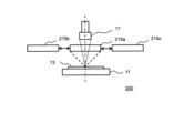
- FIG. 13 is a schematic diagram showing a visual inspection apparatus 200 according to a modified example of the present invention.
- FIG. 13 is a schematic diagram showing a visual inspection apparatus 300 including a stage 311 according to a modified example of the present invention.
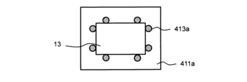
- FIG. 13 is a schematic diagram showing a stage 411 according to a modified example of the present invention.
- FIG. 13 is a schematic diagram showing a stage 411a according to a modified example of the present invention.
- FIG. 13 is a schematic diagram showing a stage 411b according to a modified example of the present invention.
- 1A to 1C are schematic diagrams illustrating a visual inspection method according to an embodiment of the present invention.
- 11A to 11C are schematic diagrams illustrating a visual inspection method according to a modified example of the present invention.
- This is an image of Comparative Example 1 in which the subject was imaged with the stage held horizontal (0°).
- 13 is an image of Example 1 in which the subject is imaged with the stage tilted at 20° with respect to the horizontal plane.
- 13 is an image of Example 2 in which the subject is imaged with the stage tilted at 10° with respect to the horizontal plane.
- FIG. 1A is a schematic diagram showing an appearance inspection apparatus 10 according to an embodiment of the present invention.
- Fig. 2 is a block diagram illustrating the configuration of the appearance inspection apparatus 10.
- the appearance inspection apparatus 10 includes a stage 11, an imaging device 17, an epi-illumination device 15, and a first actuation device 1.
- the appearance inspection apparatus 10 also includes a second actuation device 2.
- the appearance inspection apparatus 10 includes a control device 1100, an input device 1200, an output device 1300, a storage device 1400, a communication device 1500, and a power supply device 1600.
- the stage 11 is a platform on which the subject 13 is placed. In one embodiment, the stage 11 may have an anti-slip sheet on the surface on which the subject 13 is placed.
- the imaging device 17 is disposed opposite the stage 11 and is an input device for imaging the subject 13. The imaging device 17 images the subject 13 and converts it into image data.
- the imaging device 17 is a camera that acquires image data, and known imaging elements such as CCD and CMOS can be used.
- the epi-illumination device 15 is an illumination device for capturing an image of the subject 13.
- Known illumination devices such as LED illumination, incandescent lamps, or xenon lamps can be used as the epi-illumination device 15.
- the epi-illumination device 15 is disposed on the side of the stage 11 where the imaging device 17 is disposed, and is disposed in a position that does not interfere with the optical axis 19 of the imaging device 17.
- the epi-illumination device 15 is preferably a ring illumination device.
- FIG. 1B is a schematic diagram showing a conventional appearance inspection device 90.
- the appearance inspection device 90 includes a stage 91, an imaging device 97, and an epi-illumination device 95.
- the stage 91 is a platform on which the subject 13 is placed.
- the stage 91 generally has a slide mechanism that can move in the X-axis direction and the Y-axis direction in order to change the observation field of the subject 13 when observing the subject 13 with the imaging device 97.
- the stage 91 has a slide mechanism that can move in the Z-axis direction.
- the imaging device 97 may have the same configuration as the imaging device 17 described above, and is not particularly limited.
- the epi-illumination device 95 may have the same configuration as the epi-illumination device 15 described above, and is not particularly limited.
- the optical axis 99 of the imaging device 97 is aligned with the center of the illumination range of the epi-illumination device 95, and is also aligned with the normal of the subject 13 placed on the stage 91. This makes it difficult to observe defects on the surface of the subject 13.
- the appearance inspection apparatus 10 includes a first actuating device 1 capable of tilting one or more of the stage 11, the imaging device 17, and the epi-illumination device 15 with respect to a horizontal plane 12.
- FIG. 1A shows an example in which the stage 11 can be tilted with respect to the horizontal plane 12 by the first actuating device 1.
- the first actuating device 1 tilts the stage 11 by an angle ⁇ 1 from the X-axis direction to the Z-axis direction.
- FIG. 1A shows an example in which the stage 11 can be tilted with respect to the horizontal plane 12 by the first actuating device 1.
- the first actuating device 1 tilts the stage 11 by an angle ⁇ 1 from the X-axis direction to the Z-axis direction.
- FIG. 1 shows an example in which the stage 11 can be tilted with respect to the horizontal plane 12 by the first actuating device 1.
- the first actuating device 1 tilts the stage 11 by an angle ⁇ 1 from the X-axis direction to the Z-axis direction
- first actuating device 1 tilts the stage 11
- the first actuating device 1 can also tilt the stage 11 from the Z-axis direction to the X-axis direction, and can also tilt the stage 11 from the Y-axis direction to the Z-axis direction, or can tilt the stage 11 from the Z-axis direction to the Y-axis direction.
- the first actuating device 1 has a maximum bending angle of ⁇ 90° from the X-axis direction to the Z-axis direction.
- the first actuating device 1 also has a maximum bending angle of ⁇ 90° from the Y-axis direction to the Z-axis direction.
- the first actuating device 1 is capable of rotating the stage 11 in the normal direction of the stage 11, and has a rotation angle of 360°.
- the first actuating device 1 having such a maximum bending angle and rotation angle may include a parallel link mechanism.
- the second operating device 2 is further provided, which can move one or more of the stage 11, the imaging device 17, and the epi-illumination device 15 other than the stage 11, the imaging device 17, or the epi-illumination device 15 operated by the first operating device 1 in the left-right direction (first direction) of the paper, and/or the depth direction (second direction) intersecting with the first direction, and/or the up-down direction (third direction) intersecting with the first direction and the second direction.
- the first direction, the second direction, and the third direction in which the second operating device 2 moves one or more of the stage 11, the imaging device 17, and the epi-illumination device 15 are substantially orthogonal, and it is even more preferable that the first direction, the second direction, and the third direction are completely orthogonal.
- the left-right direction (first direction) of the paper is the X-axis
- the depth direction (second direction) is the Y-axis
- the up-down direction (third direction) is the Z-axis.
- the imaging device 17 and the epi-illumination device 15 are configured to be movable by the second actuation device 2.
- the imaging device 17 and the epi-illumination device 15 are moved by the second actuation device 2, it is preferable to provide an independent second actuation device 2 for each of the imaging device 17 and the epi-illumination device 15 and to control the positions of the imaging device 17 and the epi-illumination device 15 independently.
- the control device 1100 is composed of a known central processing unit (CPU), operating system (OS), and control programs or modules for controlling the appearance inspection device 10. Alternatively, the control device 1100 may be provided as a single program including the OS and the control programs or modules. The control programs or modules that constitute the control device 1100 are stored in the storage device 1400 and executed by the CPU.
- CPU central processing unit
- OS operating system
- control programs or modules for controlling the appearance inspection device 10.
- the control device 1100 may be provided as a single program including the OS and the control programs or modules.
- the control programs or modules that constitute the control device 1100 are stored in the storage device 1400 and executed by the CPU.
- the control device 1100 includes a first actuating device control unit 1110, a second actuating device control unit 1130, and a defect detection unit 1150.
- the first actuating device control unit 1110 is a program or module for controlling the operation of the first actuating device 1, and is stored in the storage device 1400 and executed by the CPU.
- the second actuating device control unit 1130 is a program or module for controlling the operation of the second actuating device 2, and is stored in the storage device 1400 and executed by the CPU.
- the defect detection unit 1150 is a program or module for analyzing image data acquired by the imaging device 17 and detecting defects, and is stored in the storage device 1400 and executed by the CPU.
- defects refers to one or more selected from scratches, foreign matter, dirt, and discoloration present on the surface of the subject 13. Therefore, the defects that the appearance inspection device 10 detects include not only two-dimensional defects such as dirt and discoloration, but also three-dimensional defects such as scratches and foreign matter that have height and depth.
- the input device 1200 is a device for operating the visual inspection device 10, and may be a known input device such as a keyboard, a mouse, or a touch panel disposed on a display device (e.g., a liquid crystal display or an organic EL display).
- the input device 1200 also includes the imaging device 17 described above.
- the output device 1300 includes a display device 1310 that displays the image captured by the imaging device 17.
- the display device 1310 may be, for example, a liquid crystal display or an organic EL display, but is not limited to these.
- the storage device 1400 is a device that stores the operating system (OS) and control programs or modules that constitute the control device 1100, the programs or modules that constitute the first operating device control unit 1110, the programs or modules that constitute the second operating device control unit 1130, and the programs or modules that constitute the defect detection unit 1150.
- the storage device 1400 is composed of, for example, a known main storage device such as a random access memory (RAM) and known auxiliary storage devices such as a read-only memory (ROM), a hard disk, or a solid-state drive (SSD) and a memory card.
- the auxiliary storage device may be arranged outside the appearance inspection device 10 and arranged on a server or network drive that can communicate via the communication device 1500.
- the communication device 1500 is a known wired or wireless communication device that can be controlled by the control device 1100.
- the communication device 1500 can be connected to a communication network such as a local area network (LAN), a wide area network (WAN), or the Internet.
- the communication device 1500 may be a communication device that conforms to a wireless communication standard such as Wi-Fi (registered trademark) (a communication means using the IEEE 802.11 standard) or Bluetooth (registered trademark).
- the communication device 1500 may perform data communication with a server or a network drive located outside the appearance inspection device 10.
- the communication device 1500 may include serial buses such as Universal Serial Bus (USB), PCI Express, and Serial ATA (SATA), and parallel buses such as Small Computer System Interface (SCSI) and Peripheral Component Interconnect (PCI).
- USB Universal Serial Bus
- SATA Serial ATA
- PCI Peripheral Component Interconnect
- the first actuator 1, the second actuator 2, and the epi-illumination device 15 can be controlled via the communication device 1500.
- the power supply device 1600 is a device that supplies external power to each device of the visual inspection device 10, and is not particularly limited.
- the subject 13 is placed on the stage 11, and the first operating device 1 tilts the stage 11 by an angle ⁇ 1 with respect to the horizontal plane 12.
- the second operating device 2 moves the image capture device 17 and the epi-illumination device 15 in the X-axis direction, the Y-axis direction, and the Z-axis direction, allowing the entire surface of the subject 13 to be imaged by the image capture device 17 and defects to be observed.
- FIG. 3A is a schematic diagram showing an appearance inspection apparatus 20 according to one embodiment of the present invention.
- the appearance inspection apparatus 20 includes a stage 21, an image capture device 27, an epi-illumination device 25, a first operating device, and a second operating device. For simplicity, the first operating device and the second operating device are omitted from FIG. 3A.
- the stage 21, the image capture device 27, and the epi-illumination device 25 have the same configuration as the stage 11, the image capture device 17, and the epi-illumination device 15 described above, respectively, and therefore detailed descriptions thereof are omitted.
- the appearance inspection apparatus 20 includes the control device 1100, the input device 1200, the output device 1300, the storage device 1400, the communication device 1500, and the power supply device 1600 described above, but detailed descriptions thereof are omitted.
- FIG. 3A shows an example in which the first operating device can tilt the epi-illumination device 25 with respect to the horizontal plane 26.
- the first operating device operates the epi-illumination device 25, and the second operating device operates the stage 21 and the imaging device 27.
- the first operating device tilts the epi-illumination device 25 from the Z-axis direction to the X-axis direction by an angle ⁇ 2.
- FIG. 3A shows an example in which the first operating device can tilt the epi-illumination device 25 with respect to the horizontal plane 26.
- the first operating device operates the epi-illumination device 25, and the second operating device operates the stage 21 and the imaging device 27.
- the first operating device tilts the epi-illumination device 25 from the Z-axis direction to the X-axis direction by an angle ⁇ 2.
- FIG. 3A shows an example in which the first operating device can tilt the epi-illumination device 25 with respect to the horizontal plane 26.
- the first operating device operates the epi-illumination device 25, and the second operating device operates the stage
- the first operating device tilts the epi-illumination device 25, and the first operating device can also tilt the epi-illumination device 25 from the X-axis direction to the Z-axis direction, tilt the epi-illumination device 25 from the Y-axis direction to the Z-axis direction, or tilt the epi-illumination device 25 from the Z-axis direction to the Y-axis direction.
- the first operating device in the appearance inspection device 20 may have the same configuration as the first operating device 1 described above, and detailed description thereof will be omitted.
- the second actuator that operates the stage 21 and the imaging device 27 may have the same configuration as the second actuator 2 described above, and detailed description thereof will be omitted.
- the subject 13 is placed on the stage 21, and the first operating device tilts the epi-illumination device 25 at an angle ⁇ 2 with respect to the horizontal plane 26.
- the second operating device moves the stage 21 in the X-axis direction, the Y-axis direction, and the Z-axis direction, so that the entire surface of the subject 13 can be imaged by the image capture device 27 and defects can be observed.
- the second operating device moves the image capture device 27 in the X-axis direction or the Y-axis direction to shift the optical axis 29 of the image capture device 27 from the center of the irradiation range of the epi-illumination device 25, so that the surface of the subject 13 can be imaged by the image capture device 27 and defects can be observed.
- FIG. 3B is a schematic diagram showing an appearance inspection device 30 according to one embodiment of the present invention.
- the appearance inspection device 30 includes a stage 31, an image capture device 37, an epi-illumination device 35, a first operating device, and a second operating device. For simplicity, the first operating device and the second operating device are omitted from FIG. 3B.
- the stage 31, the image capture device 37, and the epi-illumination device 35 have the same configuration as the stage 11, the image capture device 17, and the epi-illumination device 15 described above, respectively, and therefore detailed descriptions thereof are omitted.
- the appearance inspection device 30 includes the control device 1100, the input device 1200, the output device 1300, the storage device 1400, the communication device 1500, and the power supply device 1600 described above, but detailed descriptions thereof are omitted.
- FIG. 3B shows an example in which the first operating device can tilt the imaging device 37 with respect to a horizontal plane (in FIG. 3B, the vertical direction 33 is shown).
- the first operating device operates the imaging device 37
- the second operating device operates the stage 31 and the epi-illumination device 35.
- the first operating device tilts the imaging device 37 from the Z-axis direction to the X-axis direction by an angle ⁇ 3.
- FIG. 3B shows an example in which the first operating device can tilt the imaging device 37 with respect to a horizontal plane (in FIG. 3B, the vertical direction 33 is shown).
- the first operating device operates the imaging device 37
- the second operating device operates the stage 31 and the epi-illumination device 35.
- the first operating device tilts the imaging device 37 from the Z-axis direction to the X-axis direction by an angle ⁇ 3.
- FIG. 3B shows an example in which the first operating device can tilt the imaging device 37 with respect to a horizontal plane (in FIG. 3B, the vertical direction 33 is shown).
- the first operating device tilts the imaging device 37
- the first operating device can also tilt the imaging device 37 from the X-axis direction to the Z-axis direction, tilt the imaging device 37 from the Y-axis direction to the Z-axis direction, or tilt the imaging device 37 from the Z-axis direction to the Y-axis direction.
- the first operating device in the appearance inspection device 30 may have the same configuration as the first operating device 1 described above, and detailed description thereof will be omitted.
- the second operating device that operates the stage 31 and the epi-illumination device 35 may have the same configuration as the second operating device 2 described above, and detailed description thereof will be omitted.
- the subject 13 is placed on the stage 31, and the imaging device 37 is tilted by an angle ⁇ 3 with respect to the horizontal plane (in FIG. 3B, the vertical direction 33 is shown).
- the stage 31 is moved in the X-axis direction, Y-axis direction, and Z-axis direction by the second operating device, so that the entire surface of the subject 13 can be imaged by the imaging device 37 and defects can be observed.
- the optical axis 39 of the imaging device 37 can be shifted from the center of the irradiation range of the epi-illumination device 35 by the second operating device, so that the surface of the subject 13 can be imaged by the imaging device 37 and defects can be observed.
- FIG. 4A is a schematic diagram showing an appearance inspection device 40 according to one embodiment of the present invention.
- the appearance inspection device 40 includes a stage 41, an image capture device 47, an epi-illumination device 45, a first operating device, and a second operating device. For simplicity, the first operating device and the second operating device are omitted from FIG. 4A.
- the stage 41, the image capture device 47, and the epi-illumination device 45 have the same configuration as the stage 11, the image capture device 17, and the epi-illumination device 15 described above, respectively, and therefore detailed descriptions thereof are omitted.
- the appearance inspection device 40 includes the control device 1100, the input device 1200, the output device 1300, the storage device 1400, the communication device 1500, and the power supply device 1600 described above, but detailed descriptions thereof are omitted.
- FIG. 4A shows an example in which the first operating device allows the epi-illumination device 45 and the imaging device 47 to be tilted with respect to a horizontal plane 46 (in FIG. 4A , a vertical direction 43 is shown with respect to the imaging device 47).
- the first operating device operates the epi-illumination device 45 and the imaging device 47
- the second operating device operates the stage 41.
- the first operating device tilts the epi-illumination device 45 by an angle ⁇ 4 from the Z-axis direction to the X-axis direction
- tilts the imaging device 47 by an angle ⁇ 5 from the Z-axis direction to the X-axis direction is tilted with respect to a horizontal plane 46 (in FIG. 4A , a vertical direction 43 is shown with respect to the imaging device 47).
- the first operating device operates the epi-illumination device 45 and the imaging device 47
- the second operating device operates the stage 41.
- the first operating device tilts the epi-illumination device 45 by an angle ⁇ 4 from the Z-axis
- the first operating device in the appearance inspection device 40 may have the same configuration as the first operating device 1 described above, and detailed description will be omitted.
- the second operating device that operates the stage 41 may have the same configuration as the second operating device 2 described above, and detailed description will be omitted.
- ⁇ 4 and ⁇ 5 may be the same or different.
- the subject 13 is placed on the stage 41, and the first operating device tilts the epi-illumination device 45 at an angle ⁇ 4 with respect to a horizontal plane 46, and tilts the imaging device 47 at an angle ⁇ 5 with respect to a horizontal plane (vertical direction 43 in FIG. 4A ).
- the second operating device moves the stage 41 in the X-axis direction, Y-axis direction, and Z-axis direction, so that the entire surface of the subject 13 can be imaged by the imaging device 37 and defects can be observed.
- FIG. 4B is a schematic diagram showing an appearance inspection device 50 according to one embodiment of the present invention.
- the appearance inspection device 50 includes a stage 51, an image capture device 57, an epi-illumination device 55, a first operating device, and a second operating device. For simplicity, the first operating device and the second operating device are omitted from FIG. 4B.
- the stage 51, the image capture device 57, and the epi-illumination device 55 have the same configuration as the stage 11, the image capture device 17, and the epi-illumination device 15 described above, respectively, and therefore detailed descriptions thereof are omitted.
- the appearance inspection device 50 includes the control device 1100, the input device 1200, the output device 1300, the storage device 1400, the communication device 1500, and the power supply device 1600 described above, but detailed descriptions thereof are omitted.
- FIG. 4B shows an example in which the stage 51 and the imaging device 57 can be tilted with respect to a horizontal plane 52 (in FIG. 4B, a vertical direction 53 is shown with respect to the imaging device 57) by the first operating device.
- the first operating device operates the stage 51 and the imaging device 57
- the second operating device operates the epi-illumination device 55.
- the first operating device tilts the stage 51 from the X-axis direction to the Z-axis direction by an angle ⁇ 6
- FIG. 4B shows an example in which the stage 51 and the imaging device 57 can be tilted with respect to a horizontal plane 52 (in FIG. 4B, a vertical direction 53 is shown with respect to the imaging device 57) by the first operating device.
- the first operating device operates the stage 51 and the imaging device 57
- the second operating device operates the epi-illumination device 55.
- the first operating device tilt
- the first operating device tilts the stage 51 and the imaging device 57
- the first operating device can also tilt the stage 51 from the Z-axis direction to the X-axis direction and tilt the imaging device 57 from the X-axis direction to the Z-axis direction, and can also tilt the stage 51 and the imaging device 57 from the Y-axis direction to the Z-axis direction, or tilt the stage 51 and the imaging device 57 from the Z-axis direction to the Y-axis direction.
- the first operating device in the appearance inspection apparatus 50 may have the same configuration as the above-mentioned first operating device 1, and detailed description thereof will be omitted.
- the second operating device that operates the epi-illumination device 55 may have the same configuration as the above-mentioned second operating device 2, and detailed description thereof will be omitted.
- ⁇ 6 and ⁇ 7 may be the same or different.
- the subject 13 is placed on the stage 51, the stage 51 is tilted by an angle ⁇ 6 with respect to the horizontal plane 52 by the first operating device, and the imaging device 57 is tilted by an angle ⁇ 7 with respect to the horizontal plane (in FIG. 4B , the vertical direction 53 is shown).
- the epi-illumination device 55 is moved in the X-axis direction or Y-axis direction by the second operating device, so that the optical axis 59 of the imaging device 57 and the center of the illumination range of the epi-illumination device 55 are shifted, and the surface of the subject 13 can be imaged by the imaging device 57 to observe defects.
- FIG. 5A is a schematic diagram showing an appearance inspection device 60 according to one embodiment of the present invention.
- the appearance inspection device 60 includes a stage 61, an image capture device 67, an epi-illumination device 65, a first operating device, and a second operating device. For simplicity, the first operating device and the second operating device are omitted from FIG. 5A.
- the stage 61, the image capture device 67, and the epi-illumination device 65 have the same configuration as the stage 11, the image capture device 17, and the epi-illumination device 15 described above, respectively, and therefore detailed descriptions thereof are omitted.
- the appearance inspection device 60 includes the control device 1100, the input device 1200, the output device 1300, the storage device 1400, the communication device 1500, and the power supply device 1600 described above, but detailed descriptions thereof are omitted.
- FIG. 5A shows an example in which the stage 61 and the epi-illumination device 65 can be tilted with respect to a horizontal plane 62 (in FIG. 5A, a horizontal plane 66 is shown with respect to the epi-illumination device 65) by a first actuation device.
- the first actuation device actuates the stage 61 and the epi-illumination device 65
- the second actuation device actuates the imaging device 67.
- the first actuation device tilts the stage 61 by an angle ⁇ 8 from the X-axis direction to the Z-axis direction
- FIG. 5A shows an example in which the stage 61 and the epi-illumination device 65 can be tilted with respect to a horizontal plane 62 (in FIG. 5A, a horizontal plane 66 is shown with respect to the epi-illumination device 65) by a first actuation device
- the first operating device in the appearance inspection device 60 may have the same configuration as the first operating device 1 described above, and detailed description will be omitted.
- the second operating device that operates the imaging device 67 may have the same configuration as the second operating device 2 described above, and detailed description will be omitted.
- ⁇ 8 and ⁇ 9 may be the same or different.
- the subject 13 is placed on the stage 61, the stage 61 is tilted by an angle ⁇ 8 with respect to a horizontal plane 62 by a first operating device, and the epi-illumination device 65 is tilted by an angle ⁇ 9 with respect to a horizontal plane 66.
- the imaging device 67 is moved in the X-axis direction, Y-axis direction, and Z-axis direction by a second operating device, so that the entire surface of the subject 13 can be imaged by the imaging device 67 and defects can be observed.
- FIG. 5B is a schematic diagram showing an appearance inspection device 70 according to one embodiment of the present invention.
- the appearance inspection device 70 includes a stage 71, an image capture device 77, an epi-illumination device 75, a first operating device, and a second operating device. For simplicity, the first operating device and the second operating device are omitted from FIG. 5B.
- the stage 71, the image capture device 77, and the epi-illumination device 75 have the same configuration as the stage 11, the image capture device 17, and the epi-illumination device 15 described above, respectively, and therefore detailed descriptions thereof are omitted.
- the appearance inspection device 70 includes the control device 1100, the input device 1200, the output device 1300, the storage device 1400, the communication device 1500, and the power supply device 1600 described above, but detailed descriptions thereof are omitted.
- FIG. 5B shows an example in which the first operating device can tilt the stage 71, the epi-illumination device 75, and the imaging device 77 with respect to horizontal planes 72 and 76 (in FIG. 5B, a vertical direction 73 is shown with respect to the imaging device 77).
- the first operating device operates the stage 71, the epi-illumination device 75, and the imaging device 77.
- FIG. 5B shows an example in which the first operating device can tilt the stage 71, the epi-illumination device 75, and the imaging device 77 with respect to horizontal planes 72 and 76 (in FIG. 5B, a vertical direction 73 is shown with respect to the imaging device 77).
- the first operating device operates the stage 71, the epi-illumination device 75, and the imaging device 77.
- the first operating device tilts the stage 71 at an angle ⁇ 10 from the X-axis direction to the Z-axis direction, tilts the epi-illumination device 75 at an angle ⁇ 11 from the Z-axis direction to the X-axis direction, and tilts the imaging device 77 at an angle ⁇ 12 from the Z-axis direction to the X-axis direction.
- Fig. 10 tilts the stage 71 at an angle ⁇ 10 from the X-axis direction to the Z-axis direction
- tilts the epi-illumination device 75 at an angle ⁇ 11 from the Z-axis direction to the X-axis direction
- tilts the imaging device 77 at an angle ⁇ 12 from the Z-axis direction to the X-axis direction.
- the first operating device tilts the stage 71, the epi-illumination device 75, and the imaging device 77
- the first operating device can tilt the stage 71 from the Z-axis direction to the X-axis direction, and tilt the epi-illumination device 75 and the imaging device 77 from the X-axis direction to the Z-axis direction, and can tilt the stage 71, the epi-illumination device 75, and the imaging device 77 from the Y-axis direction to the Z-axis direction, or tilt the stage 71, the epi-illumination device 75, and the imaging device 77 from the Z-axis direction to the Y-axis direction.
- the first operating device in the appearance inspection device 70 may have the same configuration as the first operating device 1 described above, and detailed description will be omitted.
- ⁇ 10 , ⁇ 11 , and ⁇ 12 may be the same or different from each other, or two of the three may be the same.
- the subject 13 is placed on the stage 71, and the first operating device tilts the stage 71 at an angle ⁇ 10 with respect to a horizontal plane 72, tilts the epi-illumination device 75 at an angle ⁇ 11 with respect to a horizontal plane 76, and tilts the imaging device 77 at an angle ⁇ 12 with respect to the horizontal plane (in FIG. 5B , this is shown as a vertical direction 73 ).
- FIG. 6A is a schematic diagram showing an appearance inspection apparatus 100 according to one modified example.
- the appearance inspection apparatus 100 comprises a stage 111, an image capture device 17, an epi-illumination device 15, a first operating device, and a second operating device. Note that in FIG. 6A, for simplicity, the first operating device and the second operating device are omitted.
- the image capture device 17 and the epi-illumination device 15 have the configuration described above, and the basic configuration may be the same as that of the appearance inspection apparatus 10.
- the basic configuration of the appearance inspection apparatus 100 may be the same as that of the appearance inspection apparatuses 20 to 70 instead of the appearance inspection apparatus 10.
- the appearance inspection apparatus 100 further comprises a conveying device 110.
- the transport device 110 is a device for supplying the subject 13 to the stage 111 and removing the subject 13 from the stage 111 after visual inspection.
- a belt conveyor can be used as the transport device 110.
- a piece-picking robot or the like may be used together with a belt conveyor as the transport device 110 to supply the subject 13 to the stage 111 or remove it from the stage 111.
- the stage 111 may have the same configuration as the above-mentioned stages 11 to 71, except that the subject 13 is supplied to or removed from the stage 111 by the transport device 110, and a detailed description thereof will be omitted.
- FIG. 7A is a schematic diagram showing an appearance inspection device 300 equipped with a stage 311 according to one modified example.
- the appearance inspection device 300 is equipped with a stage 311, an image capture device 17, an epi-illumination device 15, a first operating device, and a second operating device.
- the first operating device and the second operating device are omitted from FIG. 7A.
- the image capture device 17 and the epi-illumination device 15 have the above-mentioned configuration, and the basic configuration may be the same as that of the appearance inspection device 10.
- the basic configuration of the appearance inspection device 300 may be the same as that of the appearance inspection devices 20 to 70 instead of the appearance inspection device 10.
- the stage 311 has a hole 301 that opens into the surface on which the subject 13 is placed. It is preferable that a plurality of holes 301 are arranged on the stage 311.
- a tube 303 is connected to the hole 301.
- One end of the tube 303 is connected to a vacuum pump 305.
- the vacuum pump 305 reduces the pressure in the hole 301 and the tube 303, and the subject 13 placed on the stage 311 is sucked in and fixed in place.
- the fixation of the subject 13 is released by stopping the vacuum pump 305 and returning the hole 301 and the tube 303 to normal pressure.
- FIG. 7B is a schematic diagram showing a stage 411 according to one modified example.
- the stage 411 may have guides 413 on the surface on which the subject 13 is placed, which prevent the subject 13 from shifting.
- the guides 413 are preferably arranged on two pairs of opposing sides, for example, so as to provide a rectangular space in which the subject 13 can be placed.
- the guides 413 are preferably not frame-shaped members, but are instead composed of four members that can be placed at a distance from one another.
- FIG. 7C is a schematic diagram showing a stage 411a according to one modified example.
- the stage 411a may have pins 413a on the surface on which the subject 13 is placed to prevent the subject 13 from shifting.
- pins 413a For the purpose of fixing the subject 13, it is preferable that three or more pins 413a are arranged on the stage 411a, and it is even more preferable that four or more pins are arranged.
- two pins 413a are arranged at each of the four corners of the subject 13 as an arrangement capable of fixing a rectangular subject 13, but this is not limited to this.
- FIG. 7D is a schematic diagram showing a stage 411b according to one modified example.
- the stage 411b may be provided with a clamp mechanism 413b on the surface on which the subject 13 is placed, which prevents the subject 13 from shifting.
- the clamp mechanisms 413b are preferably arranged on two pairs of opposing sides, for example, so as to provide a rectangular space in which the subject 13 can be placed. Note that in one modified example, the guides 413 and the clamp mechanisms 413b may be used in combination.
- stages 411 to 411b relating to these modified examples may be applied to any of the appearance inspection devices 10 to 70.
- FIG. 6B is a schematic diagram showing an appearance inspection apparatus 200 according to one modified example.
- the appearance inspection apparatus 200 includes a stage 11, an image capture device 17, a first operating device, and a second operating device. For simplicity, the first operating device and the second operating device are omitted from FIG. 6B.
- the stage 11 and the image capture device 17 have the above-described configuration, and the basic configuration may be the same as that of the appearance inspection apparatus 10.
- the basic configuration of the appearance inspection apparatus 200 may be the same as that of the appearance inspection apparatus 20 to the appearance inspection apparatus 70 instead of the appearance inspection apparatus 10.
- the appearance inspection apparatus 200 further includes an epi-illumination device including, for example, epi-illumination devices 215a to 215c.
- the incident illumination devices 215a to 215c are illumination devices that emit light of different wavelengths.
- the number of incident illumination devices can be changed as needed and is not limited to three.
- the wavelength of light emitted by the incident illumination devices can be set as desired depending on the defect to be detected.
- the incident illumination devices 215a to 215c are replaceable when observing the surface of the subject 13.
- the incident illumination devices 215a to 215c may be arranged on a disc-shaped member, and the incident illumination devices 215a to 215c may be switched by rotating the disc-shaped member.
- multiple optical filters may be arranged in a replaceable manner for one incident illumination device 15.
- Two or more of the above-mentioned modified examples may be combined and applied to the appearance inspection device 10 to the appearance inspection device 70.
- FIG. 8 is a schematic diagram for explaining an appearance inspection method according to an embodiment of the present invention.
- the appearance inspection apparatus according to the present invention encompasses various embodiments. For this reason, in FIG. 8, an appearance inspection method using the appearance inspection apparatus 10 will be described as an example.
- the subject 13 is placed on the horizontally arranged stage 11, and the stage 11 is placed in the appearance inspection device 10 (S101).
- the second actuator control unit 1130 drives the second actuator 2 to move the epi-illumination device 15 and the imaging device 17 to the imaging start point in the X-axis direction (to the left on the paper) (S103).
- the first actuator control unit 1110 drives the first actuator 1 to tilt the stage 11 from the Z-axis direction to the X-axis direction (S105).
- the angle at which the stage 11 is tilted can be set to an angle at which the defect to be detected on the surface of the subject 13 can be easily observed by the imaging device 17. Such an angle can be determined in advance using a test sample prior to the appearance inspection.
- the second actuator control unit 1130 moves the epi-illumination device 15 and the imaging device 17 in the X-axis, Y-axis, and Z-axis directions so that the positional relationship (relative angle) between the subject 13 placed on the inclined stage 11 and the epi-illumination device 15 and imaging device 17 is kept constant (S107).
- the imaging device 17 captures an image of the surface of the subject 13 and obtains image data.
- the first operating device control unit 1110 drives the first operating device 1, for example tilting the stage 11 from the X-axis direction to the Z-axis direction to change the angle at which the stage 11 is tilted (S109).
- the angle at which observation is easy using the imaging device 17 may differ depending on the type of defect, the depth of the scratch, etc. Therefore, by changing the angle at which the stage 11 is tilted, a defect different from the previously observed defect can be observed using the imaging device 17.
- the second actuator control unit 1130 moves the epi-illumination device 15 and the imaging device 17 in the X-axis, Y-axis, and Z-axis directions so that the positional relationship (relative angle) between the subject 13 placed on the inclined stage 11 and the epi-illumination device 15 and imaging device 17 is kept constant (S111).
- the imaging device 17 captures an image of the surface of the subject 13 and obtains image data.
- steps S109 and S111 By repeating steps S109 and S111, different types of defects and scratches of different depths can be observed by the imaging device 17. It is preferable to repeat steps S109 and S111 to an extent that allows the entire surface of the subject 13 to be imaged, but if the area on the surface of the subject 13 where defects will occur is known in advance, it is also possible to image only the area where the defects will occur. Furthermore, the imaging device 17 may acquire image data as a still image or as a video.
- the image data acquired by the imaging device 17 can be stored in the auxiliary storage device of the storage device 1400.
- the defect detection unit 1150 analyzes the image data acquired by the imaging device 17 or the image data stored in the storage device 1400 to detect defects.
- the method of detecting defects of the subject 13 in the image data is not particularly limited, and a known image processing method can be applied.
- the defect detection unit 1150 can detect defects, for example, from the brightness distribution or color distribution of the subject 13 in the image data. Alternatively, the defect detection unit 1150 can compare (calculate the difference) the image data of a normal product stored in the auxiliary storage device of the storage device 1400 with the image data acquired by the imaging device 17 or the image data stored in the storage device 1400, and detect the part that exceeds a predetermined threshold as a defect. Alternatively, the defect detection unit 1150 can detect defects by comparing image data acquired continuously for one subject 13.
- the normal product and the subject 13 can be simultaneously imaged using two sets of stages 11, imaging device 17, epi-illumination device 15, first operating device 1, and second operating device 2, and the defect detection unit 1150 can detect defects by comparing the image data of each of them in real time.
- the defect detection unit 1150 may perform arithmetic processing by image recognition using artificial intelligence.
- FIG. 9 is a schematic diagram for explaining the appearance inspection method according to the modified example. Steps S101 to S103 have been described above, and therefore will not be described here.
- the first operating device control unit 1110 drives the first operating device 1 to tilt the stage 11 from the Z-axis direction to the X-axis direction, captures an image of the surface of the subject 13 with the imaging device 17, and acquires image data (S205).
- the angle at which the stage 11 is tilted can be set to an angle at which the defects to be detected on the surface of the subject 13 can be easily observed by the imaging device 17. Such an angle can be determined in advance using a test sample prior to the appearance inspection.
- the first operating device control unit 1110 drives the first operating device 1 to tilt the stage 11 from the X-axis direction to the Z-axis direction, and returns the stage 11 to a horizontal position.
- the second operating device control unit 1130 moves the epi-illumination device 15 and the image capture device 17 a predetermined distance in the X-axis direction (to the left on the paper) (S207).
- the distance by which the epi-illumination device 15 and the image capture device 17 are moved can be set arbitrarily, and may be determined in advance using a test sample prior to visual inspection.
- the first actuator control unit 1110 drives the first actuator 1 to tilt the stage 11 from the Z-axis direction to the X-axis direction, captures an image of the surface of the subject 13 with the imaging device 17, and acquires image data (S209).
- the angle at which the stage 11 is tilted in step S209 may be the same as the angle at which the stage 11 was tilted in step S205, or it may be different.
- the first actuator control unit 1110 drives the first actuator 1 to tilt the stage 11 from the X-axis direction to the Z-axis direction, and returns the stage 11 to a horizontal position.
- the second actuator control unit 1130 moves the epi-illumination device 15 and the imaging device 17 a predetermined distance in the X-axis direction (to the left on the paper) (S211).
- the first actuator control unit 1110 drives the first actuator 1 to tilt the stage 11 from the Z-axis direction to the X-axis direction, captures an image of the surface of the subject 13 with the imaging device 17, and acquires image data (S213).
- the angle at which the stage 11 is tilted in step S213 may be the same as the angle at which the stage 11 is tilted in steps S205 and S209, or it may be different.
- the first actuator control unit 1110 drives the first actuator 1 to tilt the stage 11 from the X-axis direction to the Z-axis direction, and returns the stage 11 to a horizontal position.
- steps S211 and S213 By repeating steps S211 and S213, different types of defects and scratches of different depths can be observed by the imaging device 17. It is preferable to repeat steps S211 and S213 to an extent that the entire surface of the subject 13 can be imaged, but if the area on the surface of the subject 13 where defects will occur is known in advance, it is also possible to image only the area where the defects will occur. Furthermore, the imaging device 17 may acquire image data as a still image or as a video.
- the image data acquired by the imaging device 17 can be stored in the auxiliary storage device of the storage device 1400.
- the defect detection unit 1150 detects defects by analyzing the image data acquired by the imaging device 17 or the image data stored in the storage device 1400. The method of detecting defects in the subject 13 in the image data has been described above, so a detailed description will be omitted.
- the above-described appearance inspection method and its variations are merely examples, and the appearance inspection method according to the present invention can be carried out using the above-described appearance inspection devices 20 to 70 instead of the appearance inspection device 10.
- a program for executing the above-mentioned appearance inspection method can be provided.
- the program can be provided as a recording medium storing the program. This will be described with reference to FIGS. 8 and 9.
- This program places the subject 13 on the horizontally arranged stage 11, and positions the stage 11 in the visual inspection device 10 (S101). If the above-mentioned transport device 110 is provided, this program can operate the transport device 110 to place the subject 13 on the stage 11.
- This program causes the second actuator control unit 1130 to drive the second actuator 2, and moves the epi-illumination device 15 and imaging device 17 to the imaging start point in the X-axis direction (to the left of the paper) (S103).
- This program causes the first actuator control unit 1110 to drive the first actuator 1 and tilt the stage 11 from the Z-axis direction to the X-axis direction (S105).
- This program can set the angle at which the stage 11 is tilted so that the defect to be detected on the surface of the subject 13 can be easily observed by the imaging device 17. Such an angle can be determined in advance using a test sample prior to the appearance inspection.
- This program causes the second operating device control unit 1130 to move the epi-illumination device 15 and the imaging device 17 in the X-axis direction, the Y-axis direction, and the Z-axis direction so that the positional relationship (relative angle) between the subject 13 placed on the inclined stage 11 and the epi-illumination device 15 and the imaging device 17 is kept constant (S107).
- This program also causes the imaging device 17 to capture an image of the surface of the subject 13 and obtain image data.
- This program causes the first operating device control unit 1110 to drive the first operating device 1, for example by tilting the stage 11 from the X-axis direction to the Z-axis direction, thereby changing the angle at which the stage 11 is tilted (S109). Since the angle at which observation is easy using the imaging device 17 may differ depending on the type of defect, the depth of the scratch, etc., this program changes the angle at which the stage 11 is tilted, thereby allowing the imaging device 17 to capture an image of a defect different from the defect previously observed.
- This program causes the second operating device control unit 1130 to move the epi-illumination device 15 and the imaging device 17 in the X-axis direction, the Y-axis direction, and the Z-axis direction so that the positional relationship (relative angle) between the subject 13 placed on the inclined stage 11 and the epi-illumination device 15 and the imaging device 17 is kept constant (S111).
- This program also causes the imaging device 17 to capture an image of the surface of the subject 13 and obtain image data.
- this program allows different types of defects and scratches of different depths to be observed by the imaging device 17.
- the loop that repeats steps S109 and S111 is preferably set a number of times n that allows the entire surface of the subject 13 to be imaged, but if the range in which defects will occur on the surface of the subject 13 is known in advance, the number of times the loop is repeated may be set so as to image only the range in which the defects will occur.
- this program may cause the imaging device 17 to acquire image data as a still image or as a video.
- This program can store image data acquired by the imaging device 17 in the auxiliary storage device of the storage device 1400.
- This program causes the defect detection unit 1150 to analyze the image data acquired by the imaging device 17 or the image data stored in the storage device 1400 and detect defects.
- the method of detecting defects of the subject 13 in the image data executed by this program is not particularly limited, and known image processing methods can be applied.
- This program can cause the defect detection unit 1150 to detect defects, for example, from the luminance distribution or color distribution of the subject 13 in the image data.
- this program can cause the defect detection unit 1150 to compare (calculate the difference) image data of a normal product stored in the auxiliary storage device of the storage device 1400 with image data acquired by the imaging device 17 or image data stored in the storage device 1400, and detect parts that exceed a predetermined threshold as defects.
- this program can cause the defect detection unit 1150 to detect defects by comparing image data acquired continuously for one subject 13.
- this program can cause the two sets of stages 11, the imaging device 17, the epi-illumination device 15, the first operating device 1, and the second operating device 2 to operate, simultaneously capture images of a normal product and the subject 13, acquire image data for each, and cause the defect detection unit 1150 to compare the images in real time, thereby detecting defects.
- the program may cause the defect detection unit 1150 to perform computational processing using image recognition with artificial intelligence.
- This program causes the first operating device control unit 1110 to drive the first operating device 1, tilt the stage 11 from the Z-axis direction to the X-axis direction, and cause the imaging device 17 to capture an image of the surface of the subject 13, thereby acquiring image data (S205).
- This program can set the angle at which the stage 11 is tilted to an angle at which the defects to be detected on the surface of the subject 13 can be easily observed by the imaging device 17. Such an angle can be determined in advance using a test sample prior to the visual inspection.
- this program causes the first operating device control unit 1110 to drive the first operating device 1, tilt the stage 11 from the X-axis direction to the Z-axis direction, and return the stage 11 to a horizontal position.
- This program causes the second operating device control unit 1130 to move the epi-illumination device 15 and the image capture device 17 a predetermined distance in the X-axis direction (to the left on the page) (S207).
- the distance by which the epi-illumination device 15 and the image capture device 17 are moved can be set arbitrarily, and may be determined in advance using a test sample prior to visual inspection.
- This program causes the first actuator control unit 1110 to drive the first actuator 1, tilt the stage 11 from the Z-axis direction to the X-axis direction, and cause the imaging device 17 to capture an image of the surface of the subject 13, thereby acquiring image data (S209).
- the angle at which the stage 11 is tilted in step S209 may be the same as the angle at which the stage 11 is tilted in step S205, or it may be different.
- this program causes the first actuator control unit 1110 to drive the first actuator 1, tilt the stage 11 from the X-axis direction to the Z-axis direction, and return the stage 11 to a horizontal position.
- This program causes the second operating device control unit 1130 to move the epi-illumination device 15 and the imaging device 17 a predetermined distance in the X-axis direction (to the left on the paper) (S211).
- This program causes the first actuator control unit 1110 to drive the first actuator 1, tilt the stage 11 from the Z-axis direction to the X-axis direction, and cause the imaging device 17 to capture an image of the surface of the subject 13, thereby acquiring image data (S213).
- the angle at which the stage 11 is tilted in step S213 may be the same as or different from the angle at which the stage 11 is tilted in steps S205 and S209.
- this program causes the first actuator control unit 1110 to drive the first actuator 1, tilt the stage 11 from the X-axis direction to the Z-axis direction, and return the stage 11 to a horizontal position.
- this program allows different types of defects and scratches of different depths to be observed by the imaging device 17.
- the loop in which steps S211 and S213 are repeated is preferably repeated n times so as to capture an image of the entire surface of the subject 13, but if the range in which defects will occur on the surface of the subject 13 is known in advance, the number of times the loop is repeated may be set so as to capture an image of only the range in which the defects will occur.
- this program may cause the imaging device 17 to capture image data as a still image or as a video.
- This program can store image data acquired by the imaging device 17 in the auxiliary storage device of the storage device 1400.
- This program causes the defect detection unit 1150 to analyze the image data acquired by the imaging device 17 or the image data stored in the storage device 1400 to detect defects.
- the method of detecting defects in the subject 13 in the image data executed by this program has been described above, so a detailed description will be omitted.
- the above-mentioned appearance inspection program and its modified examples are merely examples, and it is possible to provide an appearance inspection program according to the present invention using the above-mentioned appearance inspection device 20 to appearance inspection device 70 instead of the appearance inspection device 10.
- Fig. 10A is an image of Comparative Example 1 in which the subject was captured with the stage horizontal (0°).
- Fig. 10B is an image of Example 1 in which the subject was captured with the stage tilted 20° from the horizontal plane. It became clear that scratches on the subject that could not be detected in the image captured with the stage horizontal could be confirmed in the image of Example 1 in which the subject was captured with the stage tilted 20° from the horizontal plane.
- Fig. 11A is an image from a reference example in which an image of a subject was captured with the stage horizontal (0°).
- Fig. 11B is an image from Example 2 in which an image of a subject was captured with the stage tilted 10° relative to the horizontal plane. It was shown that there is a difference in the shape of the scratches (holes) visible in the image captured with the stage horizontal and the image captured with the stage tilted up to 10°. In other words, it was shown that scratches on the surface of a subject can be detected from changes in the image.
- results of the above examples demonstrate that in the visual inspection of the present invention, by capturing images with one or more of the stage, imaging device, and lighting device tilted relative to the horizontal plane, defects can be detected in a manner similar to the way a person observes defects while changing the relative positions of the subject and the lighting.
Landscapes
- Physics & Mathematics (AREA)
- Health & Medical Sciences (AREA)
- Life Sciences & Earth Sciences (AREA)
- Chemical & Material Sciences (AREA)
- Analytical Chemistry (AREA)
- Biochemistry (AREA)
- General Health & Medical Sciences (AREA)
- General Physics & Mathematics (AREA)
- Immunology (AREA)
- Pathology (AREA)
- Investigating Materials By The Use Of Optical Means Adapted For Particular Applications (AREA)
Priority Applications (1)
| Application Number | Priority Date | Filing Date | Title |
|---|---|---|---|
| JP2025508135A JPWO2024195229A1 (https=) | 2023-03-23 | 2023-12-18 |
Applications Claiming Priority (2)
| Application Number | Priority Date | Filing Date | Title |
|---|---|---|---|
| JP2023-047201 | 2023-03-23 | ||
| JP2023047201 | 2023-03-23 |
Publications (1)
| Publication Number | Publication Date |
|---|---|
| WO2024195229A1 true WO2024195229A1 (ja) | 2024-09-26 |
Family
ID=92841690
Family Applications (1)
| Application Number | Title | Priority Date | Filing Date |
|---|---|---|---|
| PCT/JP2023/045315 Ceased WO2024195229A1 (ja) | 2023-03-23 | 2023-12-18 | 外観検査装置、外観検査方法及び外観検査プログラム |
Country Status (2)
| Country | Link |
|---|---|
| JP (1) | JPWO2024195229A1 (https=) |
| WO (1) | WO2024195229A1 (https=) |
Citations (9)
| Publication number | Priority date | Publication date | Assignee | Title |
|---|---|---|---|---|
| JP2000162133A (ja) * | 1998-09-21 | 2000-06-16 | Olympus Optical Co Ltd | 基板検査装置および該基板検査装置に用いられるパラレルリンク機構 |
| CN106053480A (zh) * | 2016-07-29 | 2016-10-26 | 常州大学 | 用于自动光学检测系统的四转动检测平台 |
| JP2017156242A (ja) * | 2016-03-02 | 2017-09-07 | キヤノン株式会社 | 計測装置、システム、計測方法、および物品の製造方法 |
| WO2018212058A1 (ja) * | 2017-05-18 | 2018-11-22 | Ntn株式会社 | 外観検査装置 |
| JP2019215240A (ja) * | 2018-06-12 | 2019-12-19 | シチズンファインデバイス株式会社 | 外観検査装置の教師画像生成方法 |
| JP2021039457A (ja) * | 2019-08-30 | 2021-03-11 | キヤノン株式会社 | 画像処理方法、エッジモデル作成方法、ロボットシステム、および物品の製造方法 |
| JP2021056898A (ja) * | 2019-09-30 | 2021-04-08 | キヤノン株式会社 | 画像処理方法、画像処理装置、ロボットシステム、ロボットシステムを用いた物品の製造方法、検査方法、制御プログラム及び記録媒体 |
| JP2021117159A (ja) * | 2020-01-28 | 2021-08-10 | 日本発條株式会社 | 検査システムおよび検査方法 |
| JP2023136718A (ja) * | 2022-03-17 | 2023-09-29 | 株式会社東芝 | 光学検査方法、光学検査プログラム、処理装置、及び、光学検査装置 |
-
2023
- 2023-12-18 JP JP2025508135A patent/JPWO2024195229A1/ja active Pending
- 2023-12-18 WO PCT/JP2023/045315 patent/WO2024195229A1/ja not_active Ceased
Patent Citations (9)
| Publication number | Priority date | Publication date | Assignee | Title |
|---|---|---|---|---|
| JP2000162133A (ja) * | 1998-09-21 | 2000-06-16 | Olympus Optical Co Ltd | 基板検査装置および該基板検査装置に用いられるパラレルリンク機構 |
| JP2017156242A (ja) * | 2016-03-02 | 2017-09-07 | キヤノン株式会社 | 計測装置、システム、計測方法、および物品の製造方法 |
| CN106053480A (zh) * | 2016-07-29 | 2016-10-26 | 常州大学 | 用于自动光学检测系统的四转动检测平台 |
| WO2018212058A1 (ja) * | 2017-05-18 | 2018-11-22 | Ntn株式会社 | 外観検査装置 |
| JP2019215240A (ja) * | 2018-06-12 | 2019-12-19 | シチズンファインデバイス株式会社 | 外観検査装置の教師画像生成方法 |
| JP2021039457A (ja) * | 2019-08-30 | 2021-03-11 | キヤノン株式会社 | 画像処理方法、エッジモデル作成方法、ロボットシステム、および物品の製造方法 |
| JP2021056898A (ja) * | 2019-09-30 | 2021-04-08 | キヤノン株式会社 | 画像処理方法、画像処理装置、ロボットシステム、ロボットシステムを用いた物品の製造方法、検査方法、制御プログラム及び記録媒体 |
| JP2021117159A (ja) * | 2020-01-28 | 2021-08-10 | 日本発條株式会社 | 検査システムおよび検査方法 |
| JP2023136718A (ja) * | 2022-03-17 | 2023-09-29 | 株式会社東芝 | 光学検査方法、光学検査プログラム、処理装置、及び、光学検査装置 |
Also Published As
| Publication number | Publication date |
|---|---|
| JPWO2024195229A1 (https=) | 2024-09-26 |
Similar Documents
| Publication | Publication Date | Title |
|---|---|---|
| US11818471B2 (en) | Unscanned optical inspection system using a micro camera array | |
| CN100419410C (zh) | 缺陷检查数据处理系统 | |
| US11080843B2 (en) | Image inspecting apparatus, image inspecting method and image inspecting program | |
| KR101043236B1 (ko) | Led 칩 외관 검사 장치 및 그 방법 | |
| US9140546B2 (en) | Apparatus and method for three dimensional inspection of wafer saw marks | |
| CN110186926A (zh) | 外观检查装置以及外观检查装置的照明条件设定方法 | |
| JP4085538B2 (ja) | 検査装置 | |
| CN112394071A (zh) | 基板缺陷检查装置及方法 | |
| CN116348897A (zh) | 用于可收集物品的识别及分级系统以及相关方法 | |
| JP2016166842A (ja) | 情報処理、情報処理方法、プログラム | |
| US20100053790A1 (en) | Hard disk inspection apparatus and method, as well as program | |
| CN110073203A (zh) | 检查透明基材上的缺陷的方法和设备 | |
| JP2021193744A (ja) | 半導体製造装置および半導体装置の製造方法 | |
| TW201627657A (zh) | 面板檢測裝置與方法 | |
| WO2015174114A1 (ja) | 基板検査装置 | |
| KR102368169B1 (ko) | 기판 엣지부 검사 장치, 시스템 및 검사 방법 | |
| JP6031751B2 (ja) | ガラス基板検査装置及びガラス基板製造方法 | |
| JP2007256106A (ja) | 表示パネル検査装置及びそれを用いた表示パネル検査方法 | |
| WO2024195229A1 (ja) | 外観検査装置、外観検査方法及び外観検査プログラム | |
| JP2008032433A (ja) | 基板検査装置 | |
| JP2006329714A (ja) | レンズ検査装置 | |
| KR100825968B1 (ko) | 평판 디스플레이의 가장자리 검사 장치 | |
| CN114264658B (zh) | Led芯片检测装置及设备 | |
| CN108120665A (zh) | 单色结构光检查微小颗粒的方法及设备 | |
| JP2007333672A (ja) | 外観検査装置および外観検査方法 |
Legal Events
| Date | Code | Title | Description |
|---|---|---|---|
| 121 | Ep: the epo has been informed by wipo that ep was designated in this application |
Ref document number: 23928795 Country of ref document: EP Kind code of ref document: A1 |
|
| WWE | Wipo information: entry into national phase |
Ref document number: 2025508135 Country of ref document: JP |
|
| NENP | Non-entry into the national phase |
Ref country code: DE |
|
| 122 | Ep: pct application non-entry in european phase |
Ref document number: 23928795 Country of ref document: EP Kind code of ref document: A1 |