WO2024116284A1 - 内燃機関の制御装置及び内燃機関の制御方法 - Google Patents
内燃機関の制御装置及び内燃機関の制御方法 Download PDFInfo
- Publication number
- WO2024116284A1 WO2024116284A1 PCT/JP2022/044013 JP2022044013W WO2024116284A1 WO 2024116284 A1 WO2024116284 A1 WO 2024116284A1 JP 2022044013 W JP2022044013 W JP 2022044013W WO 2024116284 A1 WO2024116284 A1 WO 2024116284A1
- Authority
- WO
- WIPO (PCT)
- Prior art keywords
- oil pressure
- period
- hydraulic pressure
- low
- internal combustion
- Prior art date
- Legal status (The legal status is an assumption and is not a legal conclusion. Google has not performed a legal analysis and makes no representation as to the accuracy of the status listed.)
- Ceased
Links
Images









Classifications
-
- F—MECHANICAL ENGINEERING; LIGHTING; HEATING; WEAPONS; BLASTING
- F01—MACHINES OR ENGINES IN GENERAL; ENGINE PLANTS IN GENERAL; STEAM ENGINES
- F01M—LUBRICATING OF MACHINES OR ENGINES IN GENERAL; LUBRICATING INTERNAL COMBUSTION ENGINES; CRANKCASE VENTILATING
- F01M1/00—Pressure lubrication
- F01M1/16—Controlling lubricant pressure or quantity
Definitions
- the present invention relates to a control device for an internal combustion engine and a control method for an internal combustion engine.
- Patent Document 1 states that "A variable displacement oil pump is a known pump that can change the oil discharge amount to two levels, high discharge amount (high oil pressure) and low discharge amount (low oil pressure), in response to a drive signal from the ECU.”
- the above-mentioned conventional technology has a two-stage hydraulic adjustment, so depending on the load, excessive hydraulic pressure may be set, making it impossible to set the optimum hydraulic pressure for the load. If the excessive hydraulic pressure is large, friction loss will be large.
- the present invention was made in consideration of these circumstances, and aims to provide an internal combustion engine control device and an internal combustion engine control method that can set the optimal hydraulic pressure according to the load.
- the control device for an internal combustion engine of the present invention which solves the above problems, is a control device for an internal combustion engine equipped with a variable displacement oil pump capable of controlling the hydraulic state, and is characterized in that it includes a hydraulic pressure setting unit that sets a high hydraulic pressure period during which a high hydraulic pressure state is maintained and a low hydraulic pressure period during which a low hydraulic pressure state is maintained for the variable displacement oil pump, and the hydraulic pressure setting unit repeatedly sets the high hydraulic pressure period and the low hydraulic pressure period according to the engine operating state.
- the control method for an internal combustion engine of the present invention for solving the above problem is a control method for an internal combustion engine equipped with a variable displacement oil pump capable of controlling the hydraulic state, and is characterized in that it has a hydraulic pressure setting step for setting a high hydraulic pressure period during which a high hydraulic pressure state is maintained and a low hydraulic pressure period during which a low hydraulic pressure state is maintained for the variable displacement oil pump, and in the hydraulic pressure setting step, the high hydraulic pressure period and the low hydraulic pressure period are repeatedly set according to the engine operating state.
- the present invention allows optimal hydraulic settings to be made according to the load.
- FIG. 1 is a block diagram showing an example of the configuration of a control device for an internal combustion engine according to an embodiment of the present invention
- 4 is a timing chart illustrating an example of the operation of the control device for an internal combustion engine according to one embodiment of the present invention.
- 4 is a flowchart illustrating an example of processing of the control device for an internal combustion engine according to one embodiment of the present invention.
- 4 is a timing chart for explaining an example of the operation of the control device for the internal combustion engine according to the first embodiment of the present invention.
- 6 is a timing chart for explaining an example of the operation of the control device for an internal combustion engine according to the second embodiment of the present invention.
- 10 is a timing chart for explaining an example of the operation of the control device for an internal combustion engine according to the fifth embodiment of the present invention.
- FIG. 4 is a characteristic diagram showing the relationship between an engine torque index and a high oil pressure period.
- 13 is a timing chart illustrating an example of the operation of the control device for an internal combustion engine according to the sixth embodiment of the present invention.
- FIG. 11 is a characteristic diagram showing the relationship between the oil temperature index and a high oil pressure period t1. 13 is a timing chart for explaining an example of the operation of the control device for an internal combustion engine according to the seventh embodiment of the present invention.
- FIG. 11 is a characteristic diagram showing the relationship between the piston temperature rise rate and the low oil pressure period t2.
- FIG. 4 is a characteristic diagram showing the relationship between the engine output index and the rate of rise in piston temperature.
- 13 is a flowchart showing an example of a process for updating a map setting value t1map for a high oil pressure period t1 and a map setting value t2map for a low oil pressure period t2.
- 13 is a flowchart showing an example of a process for updating a map setting value t2map for a low oil pressure period t2.
- 13 is a flowchart showing an example of a process for updating a map setting value t1map for a high oil pressure period t1.
- ⁇ One embodiment of the present invention> 1 is a block diagram showing an example of the configuration of a control device for an internal combustion engine according to an embodiment of the present invention.
- a period during which a high oil pressure state continues will be referred to as a high oil pressure period
- a period during which a low oil pressure state continues will be referred to as a low oil pressure period.
- the control device for an internal combustion engine is a control device for an internal combustion engine equipped with a variable displacement oil pump 20 capable of controlling the hydraulic state, and is equipped with a knock frequency determination unit 11, a hydraulic pressure switching pattern setting unit 12, a target hydraulic pressure setting unit 13, a solenoid setting unit 14, a hydraulic pressure switching pattern search unit 15, and a hydraulic pressure switching pattern learning unit 16, and is characterized by repeating periods of high hydraulic pressure and periods of low hydraulic pressure according to the engine operating state.
- the knock frequency determination unit 11 receives two inputs, the knock determination result and the oil pressure from the outside, and determines the frequency of knock occurrence, specifically, the number of knock occurrences per second, based on these two inputs.
- Examples of knock determination results include the presence or absence of knock occurrence and the intensity of the knock.
- the occurrence and intensity of knocks can be detected using a well-known knock sensor.
- the knock sensor detects the intensity of knocks (abnormal combustion) as engine block vibrations, and detects the frequency of occurrence of knocks (abnormal combustion) as engine block vibrations.
- the hydraulic switching pattern setting unit 12 has multiple maps used to set optimal patterns of high and low hydraulic pressure periods, and sets the hydraulic switching pattern by selecting one of the multiple maps based on the engine output index and the judgment result of the knock frequency judgment unit 11.
- the maps held by the hydraulic switching pattern setting unit 12 can be a map of high and low hydraulic pressure periods based on rotation, torque, and oil temperature, or a map of frequency and duty based on rotation, torque, and oil temperature.
- the frequency is the repetition frequency of the high and low hydraulic pressure periods
- the duty is the high hydraulic pressure period/(high hydraulic pressure period+low hydraulic pressure period).
- the target hydraulic pressure setting unit 13 gives instructions to the solenoid setting unit 14 to set the hydraulic pressure to a low hydraulic pressure state or a high hydraulic pressure state based on the hydraulic pressure switching pattern set by the hydraulic pressure switching pattern setting unit 12.
- the solenoid setting unit 14 sets the solenoid ON/OFF for the solenoid valve 21 of the variable displacement oil pump 20 based on instructions given by the target oil pressure setting unit 13.
- the hydraulic pressure switching pattern search unit 15 searches for optimal patterns of high hydraulic pressure periods and low hydraulic pressure periods based on the hydraulic pressure switching pattern set by the hydraulic pressure switching pattern setting unit 12 and the judgment result by the knock frequency judgment unit 11, and provides the search result to the hydraulic pressure switching pattern learning unit 16.
- the hydraulic switching pattern learning unit 16 learns the optimal patterns of high and low hydraulic periods based on the search results of the hydraulic switching pattern search unit 15, and updates the hydraulic switching pattern by feeding back the learning results to the hydraulic switching pattern setting unit 12.
- the hydraulic pressure switching pattern setting unit 12, the target hydraulic pressure setting unit 13, and the hydraulic pressure switching pattern searching unit 15 constitute a hydraulic pressure setting unit 17 that sets high hydraulic pressure periods and low hydraulic pressure periods for the variable displacement oil pump 20.
- This hydraulic pressure setting unit 17 performs control to repeatedly set high hydraulic pressure periods and low hydraulic pressure periods according to the engine operating state. This control causes high hydraulic pressure states and low hydraulic pressure states to be repeated even if the engine operating state remains constant.
- the engine operating state refers to information that indicates the operating state of the engine, and refers to an index related to engine output, an index related to temperatures such as oil/water temperature, and an index related to the occurrence state of knocking.
- the occurrence state of knocking refers to the intensity of knocking and the frequency of knocking (the number of times knocking occurs per second).
- FIG. 2 is a timing chart for explaining an example of the operation of a control device for an internal combustion engine according to one embodiment of the present invention.
- the example of the operation of the control device here basically refers to an example of the operation of the hydraulic pressure setting unit 17 in the control device. This also applies to each of the embodiments described below.
- the timing chart in Figure 2 shows the timing relationships between torque, ignition, oil pressure, and knock intensity.
- MBT for ignition is the optimal ignition timing
- OJ judgment criteria for knock intensity is the criterion for judging whether or not to perform an oil jet (OJ) to cool the piston.
- the hydraulic pressure setting unit 17 controls the hydraulic pressure to alternate between high and low hydraulic pressure states, even if the torque is constant (high torque B). Specifically, when in a high torque B state, rather than continuing the high hydraulic pressure state, the hydraulic pressure setting unit 17 controls the hydraulic pressure to alternate between high and low hydraulic pressure states by intermittently switching to low hydraulic pressure states.
- control device in controlling the repetition of high and low oil pressure states, it is important to determine how to determine the high and low oil pressure periods. Normally, increasing the oil pressure and injecting oil reduces the temperature of the piston, which should prevent knocking from occurring.
- the control device utilizes this phenomenon to search for the optimal profile (i.e., the optimal high and low oil pressure periods).
- the oil pressure is increased to high to cool the piston and oil is injected, and eventually the knock subsides and the intensity of the knock falls below the OJ judgment criterion.
- the length of the high oil pressure period is set to t1. If the oil pressure is reduced after the high oil pressure period t1 has elapsed, knocking becomes more likely to occur.
- the intensity of the knock will exceed the OJ judgment criterion, but the time from when the knock intensity begins to increase to just before it exceeds the OJ judgment criterion is calculated as t2, and this t2 is set as the length of the low oil pressure period.
- control is performed to repeat the high oil pressure period t1 and the low oil pressure period t2 multiple times.
- the low oil pressure period t2 is adjusted within a range that does not involve a change in the high oil pressure period t1. This makes it possible to minimize the high oil pressure period t1 within a range in which knock does not occur, and to search for the optimal profile (optimal high oil pressure period t1 and low oil pressure period t2).
- FIG. 3 is a flowchart illustrating an example of processing by a control device for an internal combustion engine according to one embodiment of the present invention.
- the example of processing by the control device referred to here is basically an example of processing by the hydraulic pressure setting unit 17 of the control device. That is, the series of processes described below, i.e., the series of processes for switching between a high hydraulic pressure state and a low hydraulic pressure state based on the high hydraulic pressure period t1 and the low hydraulic pressure period t2, are executed as processing in the hydraulic pressure setting step under the control of the hydraulic pressure setting unit 17.
- the hydraulic pressure setting unit 17 (description of the hydraulic pressure setting unit 17 will be omitted in the following explanation) first determines whether there has been a change in the engine operating condition (e.g., torque) (step S11), and if there has been a change in the engine operating condition (YES in S11), sets the high hydraulic pressure period t1 to the map setting value t1map and the low hydraulic pressure period t2 to the map setting value t2map (step S12).
- t1map is the map setting value (s) for the high hydraulic pressure period t1
- t2map is the map setting value (s) for the low hydraulic pressure period t2.
- t1c is the high oil pressure period count (the period during which a high oil pressure state continues) (s)
- t2c is the low oil pressure period count (the period during which a low oil pressure state continues) (s).
- step S14 it is determined whether the map setting value t1map for the high oil pressure period t1 is greater than 0 (step S14), and if t1map>0 (YES in S14), the target oil pressure is set to the high oil pressure state (step S15), and then the series of processes for switching between the high oil pressure state and the low oil pressure state is terminated.
- step S21 if t1c>t1map is not satisfied (NO in S21), the process proceeds to step S15 and the target oil pressure is set to a high oil pressure state, after which the series of processes for switching between the high oil pressure state and the low oil pressure state is terminated.
- step S23 sets the target oil pressure to a low oil pressure state, and then the series of processes for switching between a high oil pressure state and a low oil pressure state is terminated.
- the above-mentioned series of processes i.e., the series of processes executed under the control of the hydraulic pressure setting unit 17, can switch between a high hydraulic pressure state and a low hydraulic pressure state based on the high hydraulic pressure period t1 and the low hydraulic pressure period t2.
- control device performs control to repeatedly set high oil pressure period t1 and low oil pressure period t2 according to the engine operating state.
- control even if the engine operating state remains constant, high oil pressure state and low oil pressure state are repeated, so that the optimal oil pressure setting according to the load can be performed.
- knock suppression and friction loss reduction can be achieved at the same time, thereby improving the combustion performance of the system.
- control device can be used to set the optimal hydraulic pressure according to the load.
- the first embodiment of the present invention is an example of searching for a high oil pressure period t1 and a low oil pressure period t2 in which knocking does not occur, that is, a high oil pressure period t1 and a low oil pressure period t2 in which the occurrence of knocking can be suppressed.
- Fig. 4 is a timing chart for explaining an example of the operation of the control device for an internal combustion engine according to the first embodiment of the present invention.
- the high oil pressure period t1 continues until the occurrence of knock is suppressed.
- the delay occurs from increasing the oil pressure until knock is suppressed because it takes time for the piston temperature, which is a cause of knock, to decrease.
- the low oil pressure period t2 is set so that it can continue until just before a knock occurs. For this reason, the high oil pressure period t1 is continued, and then the time until just before the intensity or frequency of the knock reaches a specified value (OJ determination standard) after switching to the low oil pressure state is calculated, and this calculated time t2 is set as the low oil pressure period.
- a specified value OJ determination standard
- Example 1 under the control of the hydraulic pressure setting unit 17, a process is performed to search for a high hydraulic pressure period t1 and a low hydraulic pressure period t2 such that the intensity or frequency of knock is less than a predetermined value (e.g., a standard for OJ determination).
- a predetermined value e.g., a standard for OJ determination.
- knock can be suppressed by hydraulic control without shifting the ignition timing, so that the deterioration of combustion performance that occurs when knock is suppressed by shifting the ignition timing can be suppressed.
- a second embodiment of the present invention is an example in which a high oil pressure state and a low oil pressure state are repeatedly executed while changing a high oil pressure period t1 and a low oil pressure period t2, and an optimal high oil pressure period t1 and a low oil pressure period t2 are searched for.
- the process of the second embodiment is executed under the control of the oil pressure setting unit 17 in Fig. 1.
- Fig. 5 is a timing chart for explaining an example of the operation of the control device for an internal combustion engine according to the second embodiment of the present invention.
- the hydraulic pressure switching pattern search unit 15 of the hydraulic pressure setting unit 17 performs a process of searching for optimal high hydraulic pressure periods t1 and low hydraulic pressure periods t2 by combining and repeating multiple times high hydraulic pressure periods t1 and low hydraulic pressure periods t2 in one section of a repetition cycle of high hydraulic pressure periods t1 and low hydraulic pressure periods t2.
- the process of searching for the optimal high oil pressure period t1 and low oil pressure period t2 is performed by gradually shortening the high oil pressure period t1.
- the low oil pressure period t2 is fixed, and the process of shortening the high oil pressure period t1 so that the intensity or frequency of knock does not exceed a predetermined value (e.g., the standard for OJ determination) is performed to search for the minimum period.
- a predetermined value e.g., the standard for OJ determination
- the third embodiment of the present invention is an example in which the high oil pressure period t1 is defined by a repetition period and a duty of the high oil pressure period t1 and the low oil pressure period t2.
- the process of the third embodiment is executed under the control of the oil pressure setting unit 17 in FIG.
- a process is performed to set the high oil pressure period t1 based on the period obtained by adding up the high oil pressure period t1 and the low oil pressure period t2 in one section of a repeating period of the high oil pressure period t1 and the low oil pressure period t2, and on the duty based on the period.
- the switching between the high oil pressure period t1 and the low oil pressure period t2 is regarded as being similar to the switching between ON and OFF, and the optimal high oil pressure period t1 and low oil pressure period t2 can be set by duty control, so that control can be performed in the same way as with electronic circuits.
- a fourth embodiment of the present invention is an example in which an optimal high oil pressure period t1 and low oil pressure period t2 are set according to an engine output index or an engine temperature index. The process of the fourth embodiment is executed under the control of the oil pressure setting unit 17 in FIG.
- the engine output index is an index related to engine output from among the information showing the engine operating state.
- Examples of engine output indexes include an engine torque index and an engine speed index. As engine torque cannot be detected directly, measurable air flow rate and filling efficiency that can be calculated based on the air flow rate can be used as an index.
- Examples of engine temperature indexes include an oil temperature index and a piston temperature index.
- the hydraulic pressure switching pattern setting unit 12 of the hydraulic pressure setting unit 17 selects a map to be used for setting the pattern of the optimal high hydraulic pressure period t1 and low hydraulic pressure period t2 based on the engine output index or the engine temperature index, thereby setting the optimal high hydraulic pressure period t1 and low hydraulic pressure period t2.
- the optimal high oil pressure period t1 and low oil pressure period t2 can be set using a map according to the engine output index or engine temperature index, thereby improving the combustion performance of the system.
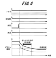
- a fifth embodiment of the present invention is an example in which the high oil pressure period t1 is set based on an engine torque index, which is an example of an engine output index.
- the high oil pressure period t1 is set so that the higher the engine torque index is, the longer the high oil pressure period t1 is.
- FIG. 6 is a timing chart for explaining an example of the operation of the control device for an internal combustion engine according to the fifth embodiment of the present invention.
- the piston temperature reaches the target temperature earlier when the engine torque index is relatively low.
- FIG. 7 shows the relationship between the engine torque index and the high oil pressure period t1. When the engine torque index is small and the condition range in which knock does not occur, the high oil pressure period t1 is 0.
- an index correlated with engine torque is used.
- an engine torque estimate estimated from a detected or estimated air flow rate can be used as an index correlated with engine torque.
- a filling efficiency correlated with engine torque can be calculated from a detected or estimated air flow rate, and used as an index correlated with engine torque.
- a sixth embodiment of the present invention is an example in which the high oil pressure period t1 is set based on an oil temperature index, which is an example of an engine temperature index.
- the high oil pressure period t1 under the control of the oil pressure setting unit 17 in Fig. 1, the high oil pressure period t1 is set so that the higher the oil temperature index is, the longer the high oil pressure period t1 is.
- FIG. 8 is a timing chart for explaining an example of the operation of the control device for an internal combustion engine according to the sixth embodiment of the present invention.
- a relatively low oil temperature index indicates that the piston temperature reaches the target temperature earlier.
- FIG. 9 shows the relationship between the oil temperature index and the high oil pressure period t1. When the oil temperature index is low and the condition range in which knock does not occur, the high oil pressure period t1 is 0.
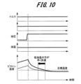
- a seventh embodiment of the present invention is an example in which the high oil pressure period t1 is set based on a piston temperature index, which is an example of an engine temperature index.
- the high oil pressure period t1 is set so that the higher the piston temperature index is, the longer the high oil pressure period t1 is.
- FIG. 10 is a timing chart for explaining an example of the operation of the control device for an internal combustion engine according to the seventh embodiment of the present invention.
- a relatively lower piston temperature index indicates that the piston temperature reaches the target temperature sooner.
- Figure 11 shows the relationship between the piston temperature index and the high oil pressure period t1.
- the high oil pressure period t1 is 0.
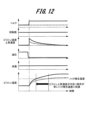
- the eighth embodiment of the present invention is an example in which the low oil pressure period t2 is set based on a piston temperature index, which is an example of an engine temperature index.
- the low oil pressure period t2 is set so that the faster the rate of rise of the piston temperature index is, the shorter the low oil pressure period t2 is.
- FIG. 12 is a timing chart for explaining an example of the operation of the control device for an internal combustion engine according to the eighth embodiment of the present invention. As shown by the dashed line, the timing chart in FIG. 12 indicates that the knock occurrence temperature is reached quickly under conditions where the piston temperature rise rate is high.
- the low oil pressure period t2 during which the low oil pressure state continues is the time it takes to reach a piston temperature at which knocking occurs. After switching from a high oil pressure state to a low oil pressure state, if the rate of rise of the piston temperature index (rate of piston temperature rise) is high, the period until knocking occurs will be short, so it is appropriate to shorten the low oil pressure period t2.
- the relationship between the rate of rise of piston temperature and the low oil pressure period t2 is shown in Figure 13.
- the rate at which piston temperature rises is proportional to the amount of heat flowing from the gas inside the engine cylinder to the piston, and this heat flow increases as engine power increases. Since engine power is proportional to engine torque and engine speed, the rate at which piston temperature rises increases as the engine power index (engine speed, engine torque) increases. The relationship between the engine power index and the rate at which piston temperature rises is shown in Figure 14.
- Example 8 by setting the low oil pressure period t2 in accordance with the actual rate of rise of the piston temperature index itself, the period of small friction loss can be extended, thereby improving the combustion performance of the system.
- a ninth embodiment of the present invention is an example in which the settings of the high oil pressure period t1 and the low oil pressure period t2 when knocking has subsided are learned to set an optimal oil pressure state for the variable displacement oil pump 20.
- the optimal oil pressure state is a oil pressure state under settings of the high oil pressure period t1 that is minimized and the low oil pressure period t2 that is maximized within a range in which knocking does not occur.
- the processing of the ninth embodiment is executed under the control of the oil pressure setting unit 17 in FIG. 1.
- the process of learning the settings for the high oil pressure period t1 and the low oil pressure period t2 when the knocking has subsided and setting the optimal oil pressure state is executed under the control of the oil pressure switching pattern learning unit 16. Specifically, this process is handled by updating the map of the high oil pressure period t1 and the low oil pressure period t2 held by the oil pressure switching pattern setting unit 12, or by updating the map of frequency and duty.
- the settings of the high oil pressure period t1 and the low oil pressure period t2 when the knocking has ceased are learned, and the optimum oil pressure state of the variable displacement oil pump 20 is set, so that the operating state of the internal combustion engine with excellent combustion performance can be maintained under the optimum oil pressure state setting.
- ft2 is a flag indicating the execution status of the update of t1map and t2map
- the update value of the map setting value t1map is being counted
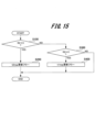
- FIG. 15 is a flowchart showing an example of processing for updating the map setting value t1map for the high oil pressure period t1 and the map setting value t2map for the low oil pressure period t2.
- a series of processes for updating the map setting values t1map, t2map is executed under the control of the oil pressure setting unit 17.
- the hydraulic pressure setting unit 17 (description of the hydraulic pressure setting unit 17 will be omitted in the following explanation) first determines whether ft2 ⁇ 3, i.e., whether the learning start setting, high hydraulic pressure operation before counting the t2map update value, or t2map update value counting is in progress (step S100). If ft2 ⁇ 3 (YES in S100), the process executes the update flow for the map setting value t2map for the low hydraulic pressure period t2 (step S200), and then ends this process.
- ft2 ⁇ 3 is not true (NO in S100)
- Map setting value t2map update flow 16 is a flowchart showing an example of the process of step S200 in FIG. 15, that is, an example of the process for updating the map setting value t2map for the low oil pressure period t2.
- a series of processes for updating the map setting value t2map for the low oil pressure period t2 is executed under the control of the oil pressure setting unit 17.
- the correction value ⁇ t1 is set based on a time corresponding to a predetermined number of cycles (e.g., the time for 100 rotations) or a predetermined time (e.g., 10 seconds) that is conducted in advance based on an experiment or simulation that takes into account the temperature change of the piston.
- step S208 for the high oil pressure period count t1c, it is judged whether t1c > t1map + ⁇ t1 (step S208), and if t1c > t1map + ⁇ t1 is not satisfied (NO in S208), the series of processes for updating the map setting value t2map is terminated.
- it is determined that ft2 2, i.e., the t2map update value is being counted (step S211), and then the target oil pressure is set to low oil pressure (step S212), and this process is then terminated.
- the process proceeds to step S212 and the target oil pressure is set to low oil pressure.
- step S213 If the knock intensity exceeds the OJ judgment standard in the judgment process of step S213 (YES in S213), the map setting value t2map is updated by t2c- ⁇ t (step S215), and then the low oil pressure period t2 is set by the map setting value t2map (step S216).
- step S2115 i.e., the update of the map setting value t2map is completed (step S217), and then the update value candidate t1map_temp for the high oil pressure period t1 is set by the map setting value t1map+correction value ⁇ t1 (step S218), and then the process proceeds to step S205 and the target oil pressure is set to high oil pressure.
- the series of processes performed by the hydraulic pressure setting unit 17 described above can realize the update process of the map setting value t2map for the low hydraulic pressure period t2.
- Map setting value t1map update flow 17 is a flowchart showing an example of the process of step S400 in FIG. 15, that is, an example of the process for updating the map setting value t1map for the high oil pressure period t1.
- a series of processes for updating the map setting value t1map for the high oil pressure period t1 is executed under the control of the oil pressure setting unit 17.
- step S403 determines whether t2c > t2map (step S403), and if t2c > t2map is not true, that is, if the low hydraulic pressure period count t2c does not exceed the map setting value t2map (NO in S403), it sets the target hydraulic pressure to low hydraulic pressure (step S404), and then ends the series of processes for updating the map setting value t1map.
- step S403 if t2c>t2map, i.e., if the low oil pressure period count t2c exceeds the map setting value t2map (YES in S403), it is judged whether the intensity of the knock exceeds the OJ determination criterion (step S405). If the intensity of the knock does not exceed the OJ determination criterion (NO in S405), the update value candidate t1map_temp for the high oil pressure period t1 is set to C*t1map_temp (C is a real number ⁇ 1) (step S406), then the target oil pressure is set to high oil pressure (step S407), and the series of processes for updating the map setting value t1map is then terminated.
- the series of processes performed by the hydraulic pressure setting unit 17 described above can realize the update process of the map setting value t1map for the high hydraulic pressure period t1.
- the present invention is not limited to the above-mentioned embodiments, and various other applications and modifications are possible without departing from the gist of the present invention as described in the claims.
- the above-mentioned embodiments are detailed and specific descriptions of the configuration of the device in order to easily explain the present invention, and are not necessarily limited to those having all of the described configurations.
- 11...knock frequency determination section 12...hydraulic pressure switching pattern setting section, 13...target hydraulic pressure setting section, 14...solenoid setting section, 15...hydraulic pressure switching pattern search section, 16...hydraulic pressure switching pattern learning section, 17...hydraulic pressure setting section, 20...variable displacement oil pump, 21...solenoid valve
Landscapes
- Engineering & Computer Science (AREA)
- Mechanical Engineering (AREA)
- General Engineering & Computer Science (AREA)
- Combined Controls Of Internal Combustion Engines (AREA)
Priority Applications (2)
| Application Number | Priority Date | Filing Date | Title |
|---|---|---|---|
| PCT/JP2022/044013 WO2024116284A1 (ja) | 2022-11-29 | 2022-11-29 | 内燃機関の制御装置及び内燃機関の制御方法 |
| JP2024561023A JP7751751B2 (ja) | 2022-11-29 | 2022-11-29 | 内燃機関の制御装置及び内燃機関の制御方法 |
Applications Claiming Priority (1)
| Application Number | Priority Date | Filing Date | Title |
|---|---|---|---|
| PCT/JP2022/044013 WO2024116284A1 (ja) | 2022-11-29 | 2022-11-29 | 内燃機関の制御装置及び内燃機関の制御方法 |
Publications (1)
| Publication Number | Publication Date |
|---|---|
| WO2024116284A1 true WO2024116284A1 (ja) | 2024-06-06 |
Family
ID=91323364
Family Applications (1)
| Application Number | Title | Priority Date | Filing Date |
|---|---|---|---|
| PCT/JP2022/044013 Ceased WO2024116284A1 (ja) | 2022-11-29 | 2022-11-29 | 内燃機関の制御装置及び内燃機関の制御方法 |
Country Status (2)
| Country | Link |
|---|---|
| JP (1) | JP7751751B2 (https=) |
| WO (1) | WO2024116284A1 (https=) |
Citations (6)
| Publication number | Priority date | Publication date | Assignee | Title |
|---|---|---|---|---|
| JPS6278421A (ja) * | 1985-09-30 | 1987-04-10 | Yamaha Motor Co Ltd | 2サイクルエンジンの潤滑方法 |
| JP2009097390A (ja) * | 2007-10-15 | 2009-05-07 | Toyota Motor Corp | エンジンの油圧制御装置 |
| JP2014159760A (ja) * | 2013-02-19 | 2014-09-04 | Toyota Motor Corp | エンジンの油圧制御装置 |
| JP2019127909A (ja) * | 2018-01-25 | 2019-08-01 | トヨタ自動車株式会社 | 内燃機関の制御装置 |
| JP2019157835A (ja) * | 2018-03-16 | 2019-09-19 | 日立オートモティブシステムズ株式会社 | 可変容量オイルポンプの制御装置及び制御方法 |
| JP2020037932A (ja) * | 2018-09-06 | 2020-03-12 | 本田技研工業株式会社 | 内燃機関の制御装置 |
Family Cites Families (2)
| Publication number | Priority date | Publication date | Assignee | Title |
|---|---|---|---|---|
| DE102012200279A1 (de) | 2012-01-11 | 2013-07-11 | Ford Global Technologies, Llc | Verfahren und Vorrichtung zum Betreiben eines Schmiersystems einesVerbrennungsmotors |
| KR102817515B1 (ko) | 2019-04-18 | 2025-06-05 | 현대자동차주식회사 | 오일 펌프 압력 제어 장치 |
-
2022
- 2022-11-29 JP JP2024561023A patent/JP7751751B2/ja active Active
- 2022-11-29 WO PCT/JP2022/044013 patent/WO2024116284A1/ja not_active Ceased
Patent Citations (6)
| Publication number | Priority date | Publication date | Assignee | Title |
|---|---|---|---|---|
| JPS6278421A (ja) * | 1985-09-30 | 1987-04-10 | Yamaha Motor Co Ltd | 2サイクルエンジンの潤滑方法 |
| JP2009097390A (ja) * | 2007-10-15 | 2009-05-07 | Toyota Motor Corp | エンジンの油圧制御装置 |
| JP2014159760A (ja) * | 2013-02-19 | 2014-09-04 | Toyota Motor Corp | エンジンの油圧制御装置 |
| JP2019127909A (ja) * | 2018-01-25 | 2019-08-01 | トヨタ自動車株式会社 | 内燃機関の制御装置 |
| JP2019157835A (ja) * | 2018-03-16 | 2019-09-19 | 日立オートモティブシステムズ株式会社 | 可変容量オイルポンプの制御装置及び制御方法 |
| JP2020037932A (ja) * | 2018-09-06 | 2020-03-12 | 本田技研工業株式会社 | 内燃機関の制御装置 |
Also Published As
| Publication number | Publication date |
|---|---|
| JPWO2024116284A1 (https=) | 2024-06-06 |
| JP7751751B2 (ja) | 2025-10-08 |
Similar Documents
| Publication | Publication Date | Title |
|---|---|---|
| KR102829825B1 (ko) | 차량의 오일펌프 제어 방법 | |
| KR100695855B1 (ko) | 엔진 토크 제어 장치 | |
| EP2050986B1 (en) | Vehicle control device | |
| CN115217576A (zh) | 机油泵电磁阀控制方法、车载控制器和汽车 | |
| US20020174841A1 (en) | Engine valve timing controller | |
| JP2008215173A (ja) | 車両の制御装置 | |
| JP7751751B2 (ja) | 内燃機関の制御装置及び内燃機関の制御方法 | |
| US7470211B2 (en) | Variable valve system of internal combustion engine and control method thereof | |
| CA2397314C (en) | Ignition timing control system and method, and engine control unit for internal combustion engine | |
| EP1830057A1 (en) | Fuel injection control device for internal combustion engine | |
| RU2638228C2 (ru) | Управляющее устройство для двигателя внутреннего сгорания | |
| CN104632448B (zh) | 牵引控制装置 | |
| JP6885291B2 (ja) | 内燃機関の制御装置 | |
| CN113586309B (zh) | 改善发动机动力不足控制方法及系统 | |
| JP2004044543A (ja) | 内燃機関のノッキング制御装置 | |
| KR20210051772A (ko) | 엔진의 과도상태 제어를 위한 물분사 방법 | |
| KR100471217B1 (ko) | 엔진 점화시기 제어 방법 및 시스템 | |
| JP6992522B2 (ja) | 内燃機関の制御装置 | |
| JP2005273572A (ja) | 内燃機関の燃焼制御装置 | |
| JP2004143969A (ja) | 内燃機関の冷却制御装置 | |
| JP2018123715A (ja) | エンジン冷却装置 | |
| JP3760549B2 (ja) | 内燃機関の可変吸気制御装置 | |
| JP6790901B2 (ja) | 内燃機関の冷却装置 | |
| JP2017155594A (ja) | 火花点火式内燃機関 | |
| JP2021060019A (ja) | 車載エンジンの制御装置 |
Legal Events
| Date | Code | Title | Description |
|---|---|---|---|
| 121 | Ep: the epo has been informed by wipo that ep was designated in this application |
Ref document number: 22967118 Country of ref document: EP Kind code of ref document: A1 |
|
| WWE | Wipo information: entry into national phase |
Ref document number: 2024561023 Country of ref document: JP |
|
| NENP | Non-entry into the national phase |
Ref country code: DE |
|
| 122 | Ep: pct application non-entry in european phase |
Ref document number: 22967118 Country of ref document: EP Kind code of ref document: A1 |