WO2024048399A1 - 作業機械 - Google Patents
作業機械 Download PDFInfo
- Publication number
- WO2024048399A1 WO2024048399A1 PCT/JP2023/030375 JP2023030375W WO2024048399A1 WO 2024048399 A1 WO2024048399 A1 WO 2024048399A1 JP 2023030375 W JP2023030375 W JP 2023030375W WO 2024048399 A1 WO2024048399 A1 WO 2024048399A1
- Authority
- WO
- WIPO (PCT)
- Prior art keywords
- gnss antenna
- seat
- antenna
- coupling member
- frame
- Prior art date
- Legal status (The legal status is an assumption and is not a legal conclusion. Google has not performed a legal analysis and makes no representation as to the accuracy of the status listed.)
- Ceased
Links
Images


Classifications
-
- B—PERFORMING OPERATIONS; TRANSPORTING
- B60—VEHICLES IN GENERAL
- B60R—VEHICLES, VEHICLE FITTINGS, OR VEHICLE PARTS, NOT OTHERWISE PROVIDED FOR
- B60R11/00—Arrangements for holding or mounting articles, not otherwise provided for
- B60R11/02—Arrangements for holding or mounting articles, not otherwise provided for for radio sets, television sets, telephones, or the like; Arrangement of controls thereof
-
- E—FIXED CONSTRUCTIONS
- E02—HYDRAULIC ENGINEERING; FOUNDATIONS; SOIL SHIFTING
- E02F—DREDGING; SOIL-SHIFTING
- E02F9/00—Component parts of dredgers or soil-shifting machines, not restricted to one of the kinds covered by groups E02F3/00 - E02F7/00
-
- E—FIXED CONSTRUCTIONS
- E02—HYDRAULIC ENGINEERING; FOUNDATIONS; SOIL SHIFTING
- E02F—DREDGING; SOIL-SHIFTING
- E02F9/00—Component parts of dredgers or soil-shifting machines, not restricted to one of the kinds covered by groups E02F3/00 - E02F7/00
- E02F9/08—Superstructures; Supports for superstructures
- E02F9/0858—Arrangement of component parts installed on superstructures not otherwise provided for, e.g. electric components, fenders, air-conditioning units
-
- E—FIXED CONSTRUCTIONS
- E02—HYDRAULIC ENGINEERING; FOUNDATIONS; SOIL SHIFTING
- E02F—DREDGING; SOIL-SHIFTING
- E02F9/00—Component parts of dredgers or soil-shifting machines, not restricted to one of the kinds covered by groups E02F3/00 - E02F7/00
- E02F9/16—Cabins, platforms, or the like, for drivers
- E02F9/163—Structures to protect drivers, e.g. cabins, doors for cabins; Falling object protection structure [FOPS]; Roll over protection structure [ROPS]
-
- H—ELECTRICITY
- H01—ELECTRIC ELEMENTS
- H01Q—ANTENNAS, i.e. RADIO AERIALS
- H01Q1/00—Details of, or arrangements associated with, antennas
- H01Q1/12—Supports; Mounting means
- H01Q1/22—Supports; Mounting means by structural association with other equipment or articles
- H01Q1/24—Supports; Mounting means by structural association with other equipment or articles with receiving set
- H01Q1/241—Supports; Mounting means by structural association with other equipment or articles with receiving set used in mobile communications, e.g. GSM
-
- H—ELECTRICITY
- H01—ELECTRIC ELEMENTS
- H01Q—ANTENNAS, i.e. RADIO AERIALS
- H01Q1/00—Details of, or arrangements associated with, antennas
- H01Q1/27—Adaptation for use in or on movable bodies
- H01Q1/32—Adaptation for use in or on road or rail vehicles
- H01Q1/3208—Adaptation for use in or on road or rail vehicles characterised by the application wherein the antenna is used
- H01Q1/3233—Adaptation for use in or on road or rail vehicles characterised by the application wherein the antenna is used particular used as part of a sensor or in a security system, e.g. for automotive radar, navigation systems
-
- H—ELECTRICITY
- H01—ELECTRIC ELEMENTS
- H01Q—ANTENNAS, i.e. RADIO AERIALS
- H01Q1/00—Details of, or arrangements associated with, antennas
- H01Q1/27—Adaptation for use in or on movable bodies
- H01Q1/32—Adaptation for use in or on road or rail vehicles
- H01Q1/325—Adaptation for use in or on road or rail vehicles characterised by the location of the antenna on the vehicle
-
- B—PERFORMING OPERATIONS; TRANSPORTING
- B60—VEHICLES IN GENERAL
- B60Y—INDEXING SCHEME RELATING TO ASPECTS CROSS-CUTTING VEHICLE TECHNOLOGY
- B60Y2200/00—Type of vehicle
- B60Y2200/40—Special vehicles
- B60Y2200/41—Construction vehicles, e.g. graders, excavators
Definitions
- the present disclosure relates to a work machine.
- GNSS Global Navigation Satellite System
- an antenna is arranged at the tip of a mast that is erected on the upper surface of the vehicle body.
- the antenna when the antenna is placed at the tip of the mast, the antenna can be easily removed from the outside, making it easy for the antenna to be stolen. Therefore, in order to prevent theft, it is necessary to remove the antenna from the mast after the work is completed, which is cumbersome. Furthermore, there is a risk that the harness will deteriorate as the antenna is repeatedly attached and detached.
- the present disclosure aims to provide a working machine that prevents antenna removal from the outside.
- a working machine includes a vehicle upper surface frame, a housing space, and a fixing part.
- the accommodation space is located below the vehicle body top frame.
- the fixing portion fixes the antenna to the vehicle top frame from inside the accommodation space so that at least a portion of the antenna is disposed above the vehicle top frame.
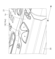
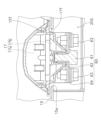
- FIG. 1 is a rear perspective view of the hydraulic excavator 1.
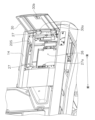
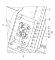
- FIG. 2 is a left perspective view of the exterior cover 13.
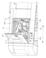
- FIG. 3 is a right front perspective view of the exterior cover 13.
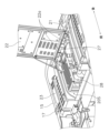
- FIG. 4 is a right perspective view of the exterior cover 13.
- FIG. 5 is a left front perspective view of the exterior cover 13.
- the hydraulic excavator 1 is an example of a "work machine” according to the present disclosure.
- the hydraulic excavator 1 includes a lower traveling body 10, an upper revolving body 11, a counterweight 12, an exterior cover 13, a left body top frame 14, a right body top frame 15, a first GNSS antenna 16, a second GNSS antenna 17, a working machine 18, and a cab. 19.
- the upper revolving body 11, the counterweight 12, the exterior cover 13, the left body top frame 14, the right body top frame 15, and the cab 19 constitute the main parts of the body of the hydraulic excavator 1.
- Each of the first GNSS antenna 16 and the second GNSS antenna 17 is an example of an "antenna" according to the present disclosure.
- the lower traveling body 10 has a pair of crawler tracks (only the left crawler track is shown in FIG. 1) that can rotate independently of each other.
- the hydraulic excavator 1 can move forward, backward, left and right by rotating a pair of crawler tracks.
- the upper rotating body 11 is arranged on the lower traveling body 10.
- the upper revolving body 11 is rotatable.
- the upper revolving body 11 supports a counterweight 12, an exterior cover 13, a working machine 18, and a cab 19.
- the counterweight 12 is arranged on the rear end of the upper revolving body 11.
- the counterweight 12 is constructed by, for example, placing concrete or the like in a box made of a steel plate.
- the counterweight 12 is used to maintain the balance of the vehicle body during excavation work and the like.
- the exterior cover 13 is placed on the upper revolving body 11.
- the exterior cover 13 is arranged in front of the counterweight 12 and behind the cab 19. As shown in FIGS. 2 to 4, the exterior cover 13 is attached to the support frame 27.
- the support frame 27 is arranged on the upper revolving body 11.
- the support frame 27 is arranged along the outer edge of the equipment room 20S, which will be described later.
- the exterior cover 13 includes a vehicle body top cover 20, a left side cover 30, and a right side cover 40.
- the vehicle body top cover 20 is divided into a left top cover 21, an engine hood 22, and a right top cover 23.
- an equipment room 20S is located below the vehicle body top cover 20.
- the equipment room 20S includes cooling equipment 26 (see Figure 2) such as a radiator and cooling fan, a heat source 28 (see Figure 3) such as an engine and exhaust gas treatment device, and auxiliary equipment such as a hydraulic oil tank, a hydraulic oil pump, and a fuel tank. Class 29 (see Figure 4) is arranged.
- the equipment room 20S is an example of a "accommodation space" according to the present disclosure. Note that FIG. 2 shows the left side cover 30 in an open state, FIG. 3 shows the engine hood 22 in an open state, and FIG. 4 shows the right side cover 40 in an open state.
- the cooling device 26 is arranged below the left upper cover 21 and the engine hood 22, the heat source 28 is arranged below the engine hood 22 and the right upper cover 23, and the auxiliary equipment 29 is arranged below the left upper cover 21 and the engine hood 22. It is arranged below the top cover 23.
- the left upper surface cover 21 is arranged on the left side of the engine hood 22.
- the left upper cover 21 is fixed to the support frame 27 with bolts and cannot be opened or closed.
- the engine hood 22 is arranged between the left upper cover 21 and the right upper cover 23 in the vehicle width direction. As shown in FIG. 3, the rear end portion of the engine hood 22 is supported by a hinge 22a so as to be openable and closable.
- the hinge 22a is connected to the engine hood 22 and the support frame 27.
- the engine hood 22 can be opened and closed between a closed position (see FIG. 1) and an open position (see FIG. 3).
- the upper right surface cover 23 is arranged on the right side of the engine hood 22.
- the upper right surface cover 23 is fixed to the support frame 27 by bolts and cannot be opened or closed.
- the left side cover 30 is arranged to the lower left of the left upper cover 21.
- the left side cover 30 covers the side (left side) of the equipment room 20S.
- the rear end portion of the left side cover 30 is supported by a hinge 30a so as to be openable and closable.
- the hinge 30a is connected to the left side cover 30 and the support frame 27.
- the left side cover 30 can be opened and closed between a closed position (see FIG. 1) and an open position (see FIG. 2).
- the left side cover 30 has a locking mechanism 30b. By locking the latch of the locking mechanism 30b to the latch receiver 27a attached to the support frame 27, the left side cover 30 can be locked in the closed position.
- the right side cover 40 is arranged to the lower right of the right upper cover 23.
- the right side cover 40 covers the side (right side) of the equipment room 20S. Similar to the left side cover 30, the rear end of the right side cover 40 is supported by a hinge (not shown) so that it can be opened and closed.
- the right side cover 40 can be opened and closed between a closed position and an open position (see FIG. 4).
- the right side cover 40 has a locking mechanism 40b. By locking the latch of the locking mechanism 40b to the latch receiver 27b attached to the support frame 27, the right side cover 40 can be locked in the closed position.
- the left vehicle body top frame 14 is arranged on the support frame 27.
- the left vehicle body top frame 14 extends along the front-rear direction.
- the left vehicle body top frame 14 is arranged to the left of the vehicle body top cover 20 (specifically, the left top cover 21) and above the left side cover 30.
- a first GNSS antenna 16 is fixed to the left vehicle upper surface frame 14.
- the left vehicle body top frame 14 is an example of a "vehicle body top frame" according to the present disclosure.
- the right vehicle body top frame 15 is arranged on the support frame 27.
- the right vehicle body upper surface frame 15 extends along the front-rear direction.
- the right body top frame 15 is arranged to the right of the vehicle body top cover 20 (specifically, the right top cover 23) and above the right side cover 40.
- a second GNSS antenna 17 is fixed to the right vehicle upper frame 15.
- the right vehicle body top frame 15 is an example of a "vehicle body top frame" according to the present disclosure.
- the first GNSS antenna 16 is an antenna used for GNSS (Global Navigation Satellite System). As shown in FIG. 1, the first GNSS antenna 16 is fixed to the left vehicle upper frame 14. At least a portion of the first GNSS antenna 16 is arranged above the left vehicle upper frame 14. The first GNSS antenna 16 is arranged at the rear of the cab 19. The first GNSS antenna 16 is connected to the controller 19a inside the cab 19 via the first harness H1. The first harness H1 extends from the first GNSS antenna 16 toward the right front. The fixing structure of the first GNSS antenna 16 will be described later.
- GNSS Global Navigation Satellite System
- the second GNSS antenna 17 is an antenna used for GNSS. As shown in FIG. 1, the second GNSS antenna 17 is fixed to the right vehicle upper frame 15. At least a portion of the second GNSS antenna 17 is arranged above the right vehicle upper surface frame 15. The second GNSS antenna 17 is arranged on the opposite side of the first GNSS antenna 16 with respect to the center of the hydraulic excavator 1 in the vehicle width direction. The second GNSS antenna 17 is connected to the controller 19a inside the cab 19 via the second harness H2. The second harness H2 extends from the second GNSS antenna 17 toward the left front. The fixing structure of the second GNSS antenna 17 will be described later.
- the first GNSS antenna 16 is placed on the left side of the vehicle top cover 20, and the second GNSS antenna 17 is placed on the right side of the car body top cover 20.
- the distance between the first GNSS antenna 16 and the second GNSS antenna 17 can be secured in the vehicle width direction, so that the accuracy of the calculation result of the vehicle body direction using the positioning results of each antenna can be improved.
- the first GNSS antenna 16 is arranged at the rear end of the left vehicle upper frame 14, and the second GNSS antenna 17 is arranged at the front end of the right vehicle upper frame 15.
- the first GNSS antenna 16 located behind the cab 19 is located at the rear end of the left vehicle upper frame 14. This allows the first GNSS antenna 16 to be separated from the cab 19, thereby increasing the sky factor of the first GNSS antenna 16. As a result, the positioning accuracy of the first GNSS antenna 16 can be improved.
- the work machine 18 is swingably attached to the front end of the revolving upper structure 11.
- the work machine 18 is arranged on the side of the cab 19.
- the cab 19 is arranged on the upper revolving body 11.
- Cab 19 is arranged in front of exterior cover 13.
- the cab 19 is arranged on the side of the work machine 18.
- a driver's seat and an operation section may be arranged inside the cab 19.
- FIG. 6 is a rear perspective view of the first GNSS antenna 16.
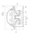
- FIG. 7 is a cross-sectional view of the fixing structure of the first GNSS antenna 16.
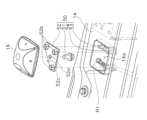
- FIG. 8 is an exploded perspective view of the fixing structure of the first GNSS antenna 16.
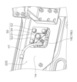
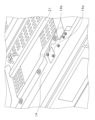
- FIG. 9 is a downward perspective view of the fixing structure of the first GNSS antenna 16 viewed from inside the equipment room 20S.
- the first GNSS antenna 16 has an upper portion 16a and a lower portion 16b.
- the upper portion 16a is a portion of the first GNSS antenna 16 that is disposed above the left vehicle upper surface frame 14.
- the lower portion 16b is a portion of the first GNSS antenna 16 that is inserted into the opening 14a of the left vehicle upper frame 14.
- the upper part 16a is cone-shaped. This makes it difficult to grasp the upper part 16a of the first GNSS antenna 16 by hand or with a tool, thereby preventing the first GNSS antenna 16 from being removed from the outside of the left vehicle upper frame 14.
- the lower portion 16b has an outer surface 16T that faces the inner surface 14T of the opening 14a of the left vehicle upper surface frame 14.
- the outer surface 16T of the lower portion 16b comes into contact with the inner surface 14T of the opening 14a. Therefore, since the first GNSS antenna 16 itself cannot be rotated, it is possible to prevent the first GNSS antenna 16 from being removed from the outside of the left vehicle upper surface frame 14.
- the first GNSS antenna 16 is fixed to the left vehicle upper frame 14 from inside the equipment room 20S by the fixing part 50.
- the GNSS antenna is fixed to the frame means that the GNSS antenna attached to the frame is removable from the inside of the frame and non-removable from the outside of the frame.
- the fixing part 50 has a first coupling member 51, a first seat 52, a second coupling member 53, and a second seat 54.
- the first coupling member 51 fixes the first GNSS antenna 16 to the left vehicle upper frame 14.
- the first coupling member 51 is fastened to the first GNSS antenna 16 from inside the equipment room 20S.
- the first coupling member 51 is inserted into the insertion hole 52a of the first seat 52.
- the first coupling member 51 is fastened to the first GNSS antenna 16 from below.
- the first coupling member 51 is fastened to the lower part of the first GNSS antenna 16 .
- one first coupling member 51 is fastened to the center of the first GNSS antenna 16, but the number and arrangement of the first coupling members 51 can be changed as appropriate.
- first coupling member 51 may be any member as long as it can couple the first GNSS antenna 16 to the first seat 52.
- first coupling member 51 may be a clamp or a joint formed by welding.
- the first seat 52 is a plate-like member.
- the first seat 52 is arranged below the opening 14a of the left vehicle upper frame 14.
- the first GNSS antenna 16 is arranged on the first seat 52.
- the first seat 52 is arranged approximately parallel to the left vehicle upper surface frame 14 in the equipment room 20S.
- the first seat 52 has an insertion hole 52a, a nut 52b, and a notch 52c.
- the first coupling member 51 is inserted into the insertion hole 52a.
- the nut 52b is fixed to the upper surface of the first seat 52.
- a second coupling member 53 is fastened to the nut 52b.
- the notch 52c is provided to pass the first harness H1 to the first GNSS antenna 16 side. In this embodiment, since the first harness H1 extends toward the right front from the first GNSS antenna 16, a notch 52c is formed at the front right corner of the first seat 52.
- the second coupling member 53 couples the first seat 52 to the second seat 54.
- the second coupling member 53 is inserted through the second seat 54 and the first seat 52 and fastened to the nut 52b of the first seat 52. This couples the second seat 54 to the first seat 52.
- the three second coupling members 53 are arranged in an L-shape, but the number and arrangement of the second coupling members 53 can be changed as appropriate.
- a bolt is used as the second coupling member 53, but the second coupling member 53 may be any member as long as it can couple the first seat 52 to the second seat 54.
- the second coupling member 53 may be a clamp or a joint formed by welding.
- the second seat 54 is fixed to the left vehicle upper surface frame 14.
- the outer edge of the second seat 54 is welded to the inner surface of the left vehicle body top frame 14, but the method of fixing the second seat 54 to the left vehicle body top frame 14 is not particularly limited.
- the first seat 52 is coupled to the second seat 54 by a second coupling member 53.
- the coupling of the first seat 52 to the second seat 54 may be performed after coupling the first GNSS antenna 16 to the first seat 52 or before coupling the first GNSS antenna 16 to the first seat 52. may be carried out.
- the first GNSS antenna 16 does not need to be removed on a daily basis, but may need to be removed, for example, in the event of a failure.
- the first removal method is as follows. First, as shown in FIG. 2, the left side cover 30 is unlocked and the left side cover 30 is opened to the open position. Next, the first harness H1 shown in FIG. 9 is pulled out from the first GNSS antenna 16 in the equipment room 20S. Next, in the equipment room 20S, the first coupling member 51 shown in FIG. 9 is loosened and removed from the first GNSS antenna 16. Next, the first GNSS antenna 16 is lifted from above the left vehicle body top frame 14 and removed from the vehicle body. Next, the left side cover 30 is returned to the closed position and locked.
- the second removal method is as follows. First, as shown in FIG. 2, the left side cover 30 is unlocked and the left side cover 30 is opened to the open position. Next, the first harness H1 shown in FIG. 9 is pulled out from the first GNSS antenna 16 in the equipment room 20S. Next, in the equipment room 20S, the second coupling member 53 shown in FIG. 9 is loosened and removed from the second seat 54. Next, the first GNSS antenna 16 to which the first seat 52 is coupled is lifted from above the left vehicle body top frame 14 and removed from the vehicle body. Next, the left side cover 30 is returned to the closed position and locked. Next, the first seat 52 is removed from the first GNSS antenna 16 by loosening the first coupling member 51 and pulling it out from the first GNSS antenna 16 .
- the first attachment method is as follows. First, as shown in FIG. 6, the first GNSS antenna 16 is inserted into the opening 14a from above the left vehicle body top frame 14. Next, as shown in FIG. 2, the left side cover 30 is unlocked and the left side cover 30 is opened to the open position. Next, the first seat 52 is coupled to the first GNSS antenna 16 by fastening the first coupling member 51 to the first GNSS antenna 16 through the insertion hole 52a of the first seat 52 from inside the equipment room 20S. do. Next, the first harness H1 is inserted into the first GNSS antenna 16 from inside the equipment room 20S. Next, the left side cover 30 is returned to the closed position and locked.
- the second attachment method is as follows. First, the first seat 52 is coupled to the first GNSS antenna 16 by fastening the first coupling member 51 to the first GNSS antenna 16 through the insertion hole 52a of the first seat 52. Next, the first GNSS antenna 16 to which the first seat 52 is coupled is inserted into the opening 14a from above the left vehicle body upper frame 14. Next, as shown in FIG. 2, the left side cover 30 is unlocked and the left side cover 30 is opened to the open position. Next, the second seat 54 is coupled to the first seat 52 by fastening the second coupling member 53 to the nut 52b of the first seat 52 from inside the equipment room 20S. Next, the first harness H1 is inserted into the first GNSS antenna 16 from inside the equipment room 20S. Next, the left side cover 30 is returned to the closed position and locked.
- the first GNSS antenna 16 is fixed to the left vehicle upper surface frame 14 from inside the equipment room 20S by the fixing part 50, the first GNSS antenna 16 is attached to the first coupling member 51 or the second coupling member from the inside of the equipment room 20S. 53, the first GNSS antenna 16 cannot be attached or detached.
- the cooling device 26 is disposed across the left upper cover 21 and the lower part of the engine hood 22, so it is impossible to access the fixed part 50 of the first GNSS antenna 16. Can not. Therefore, the first GNSS antenna 16 cannot be attached or detached unless the left side cover 30 is unlocked.
- FIG. 10 is a rear perspective view of the second GNSS antenna 17.
- FIG. 11 is a cross-sectional view of the fixing structure of the second GNSS antenna 17.
- FIG. 12 is an exploded perspective view of the fixing structure of the second GNSS antenna 17.
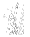
- FIG. 13 is a perspective view of the heat insulating material 65 viewed from inside the equipment room 20S.
- FIG. 14 is a downward perspective view showing a state in which the first heat insulating material 65, second heat insulating material 66, and fixture 67 of FIG. 13 are removed.
- the second GNSS antenna 17 has an upper portion 17a and a lower portion 17b.
- the upper portion 17a is a portion of the second GNSS antenna 17 that is disposed above the right vehicle upper surface frame 15.
- the lower portion 17b is a portion of the second GNSS antenna 17 that is inserted into the opening 15a of the right vehicle upper frame 15.
- the upper part 17a is cone-shaped. This makes it difficult to grasp the upper part 17a of the second GNSS antenna 17 by hand or with a tool, thereby preventing the second GNSS antenna 17 from being removed from the outside of the right vehicle upper frame 15.
- the lower portion 17b has an outer surface 17T that faces the inner surface 15T of the opening 15a of the right vehicle upper surface frame 15.
- the outer surface 17T of the lower portion 17b comes into contact with the inner surface 15T of the opening 15a. Therefore, since the second GNSS antenna 17 itself cannot be rotated, it is possible to prevent the second GNSS antenna 17 from being removed from the outside of the right vehicle upper surface frame 15.
- the second GNSS antenna 17 is fixed to the right vehicle upper frame 15 from inside the equipment room 20S by the fixing part 60.
- the fixing part 60 includes a first coupling member 61, a first seat 62, a second coupling member 63, a second seat 64, a first heat insulating material 65, a second heat insulating material 66, and a fitting 67.
- the first coupling member 61 fixes the second GNSS antenna 17 to the right vehicle upper frame 15.
- the first coupling member 61 is fastened to the second GNSS antenna 17 from inside the equipment room 20S.
- the first coupling member 61 is inserted into the insertion hole 62a of the first seat 62.
- the second GNSS antenna 17 is coupled to the first seat 62 by fastening the first coupling member 61 to the second GNSS antenna 17 .
- the first coupling member 61 is fastened to the second GNSS antenna 17 from below.
- the first coupling member 61 is fastened to the lower part of the second GNSS antenna 17 .
- first coupling member 61 is fastened to the center of the second GNSS antenna 17, but the number and arrangement of the first coupling members 61 can be changed as appropriate.
- a bolt is used as the first coupling member 61, but the first coupling member 61 may be any member as long as it can couple the second GNSS antenna 17 to the first seat 62.
- the first coupling member 61 may be a clamp or a joint formed by welding.
- the first seat 62 is a plate-like member.
- the first seat 62 is arranged below the opening 15a of the right vehicle upper frame 15.
- the second GNSS antenna 17 is arranged on the first seat 62.
- the first seat 62 is arranged approximately parallel to the right vehicle upper surface frame 15 in the equipment room 20S.
- the first seat 62 has an insertion hole 62a, a nut 62b, and a notch 62c.
- the first coupling member 61 is inserted into the insertion hole 62a.
- the nut 62b is fixed to the upper surface of the first seat 62.
- a second coupling member 63 is fastened to the nut 62b.
- the notch 62c is provided to pass the second harness H2 to the second GNSS antenna 17 side. In this embodiment, since the second harness H2 extends from the second GNSS antenna 17 toward the left front, a notch 62c is formed at the front left corner of the first seat 62.
- the second coupling member 63 couples the first seat 62 to the second seat 64.
- the second coupling member 63 is inserted through the second seat 64 and the first seat 62 and fastened to the nut 62b of the first seat 62. This couples the second seat 64 to the first seat 62.
- the three second coupling members 63 are arranged in an L-shape, but the number and arrangement of the second coupling members 63 can be changed as appropriate.
- a bolt is used as the second coupling member 63, but the second coupling member 63 may be any member as long as it can couple the first seat 62 to the second seat 64.
- the second coupling member 63 may be a clamp or a joint formed by welding.
- the second seat 64 is fixed to the right vehicle upper surface frame 15.
- the outer edge of the second seat 64 is welded to the inner surface of the right vehicle body top frame 15, but the method of fixing the second seat 64 to the right vehicle body top frame 15 is not particularly limited.
- the first seat 62 is coupled to the second seat 64 by a second coupling member 63.
- the coupling of the first seat 62 to the second seat 64 may be performed after coupling the second GNSS antenna 17 to the first seat 62, or before coupling the second GNSS antenna 17 to the first seat 62. may be carried out.
- the first heat insulating material 65 and the second heat insulating material 66 are arranged between the second GNSS antenna 17 and the heat source 28 in the equipment room 20S.
- the first heat insulating material 65 is arranged below the second GNSS antenna 17.
- the second heat insulating material 66 is arranged on the side of the second GNSS antenna 17.
- the first heat insulating material 65 is formed with an insertion hole 65a through which the second harness H2 is inserted.
- the first heat insulating material 65 and the second heat insulating material 66 are fixed to a fixture 67.
- well-known heat insulating materials can be used as the first heat insulating material 65 and the second heat insulating material 66.
- the attachment 67 is attached to the support member 68 with three bolts 67a.
- the support member 68 is welded to the right vehicle upper surface frame 15.
- the method of fixing the support member 68 to the right vehicle upper surface frame 15 is not particularly limited, and for example, a clamp or a bolt may be used.
- the first and second methods of removing the second GNSS antenna 17 will be explained. Although it is not necessary to remove the second GNSS antenna 17 on a daily basis, it is necessary to remove it in the event of a failure, for example.
- the first removal method is as follows. First, as shown in FIG. 4, the right side cover 40 is unlocked and the right side cover 40 is opened to the open position. Next, in the equipment room 20S, the attachment 67 shown in FIG. 13 is removed. Next, the second harness H2 shown in FIG. 14 is pulled out from the second GNSS antenna 17 in the equipment room 20S. Next, in the equipment room 20S, the first coupling member 61 shown in FIG. 14 is loosened and removed from the second GNSS antenna 17. Next, the second GNSS antenna 17 is lifted from above the right vehicle body top frame 15 and removed from the vehicle body. Next, the right side cover 40 is returned to the closed position and locked.
- the second removal method is as follows. First, as shown in FIG. 4, the right side cover 40 is unlocked and the right side cover 40 is opened to the open position. Next, in the equipment room 20S, after loosening and removing the three bolts 67a shown in FIG. 13, the attachment 67 is removed from the support member 68. Next, the second harness H2 shown in FIG. 14 is pulled out from the second GNSS antenna 17 in the equipment room 20S. Next, in the equipment room 20S, the second coupling member 63 shown in FIG. 14 is loosened and removed from the second seat 64. Next, the second GNSS antenna 17 to which the first seat 62 is coupled is lifted from above the right vehicle body top frame 15 and removed from the vehicle body. Next, the right side cover 40 is returned to the closed position and locked. Next, the first seat 62 is removed from the second GNSS antenna 17 by loosening the first coupling member 61 and pulling it out from the second GNSS antenna 17 .
- the first attachment method is as follows. First, as shown in FIG. 10, the second GNSS antenna 17 is inserted into the opening 15a from above the right vehicle body upper frame 15. Next, as shown in FIG. 4, the right side cover 40 is unlocked and the right side cover 40 is opened to the open position. Next, the first coupling member 61 is fastened to the second GNSS antenna 17 from inside the equipment room 20S through the insertion hole 62a of the first seat 62, thereby coupling the first seat 62 to the second GNSS antenna 17. do. Next, the second harness H2 is inserted into the second GNSS antenna 17 from inside the equipment room 20S. Next, as shown in FIG. 13, a fitting 67 to which the first heat insulating material 65 and the second heat insulating material 66 are attached is attached to the support member 68. Next, the right side cover 40 is returned to the closed position and locked.
- the second attachment method is as follows. First, the first seat 62 is coupled to the second GNSS antenna 17 by fastening the first coupling member 61 to the second GNSS antenna 17 through the insertion hole 62a of the first seat 62. Next, the second GNSS antenna 17 to which the first seat 62 is coupled is inserted into the opening 15a from above the right vehicle upper frame 15. Next, as shown in FIG. 4, the right side cover 40 is unlocked and the right side cover 40 is opened to the open position. Next, the second seat 64 is coupled to the first seat 62 by fastening the second coupling member 63 to the nut 62b of the first seat 62 from inside the equipment room 20S.
- the second harness H2 is inserted into the second GNSS antenna 17 from inside the equipment room 20S.
- a fitting 67 to which the first heat insulating material 65 and the second heat insulating material 66 are attached is attached to the support member 68.
- the right side cover 40 is returned to the closed position and locked.
- the second GNSS antenna 17 is fixed to the right vehicle upper frame 15 from the inside of the equipment room 20S by the fixing part 60, the first coupling member 61 or the second coupling member is attached from the inside of the equipment room 20S. 63, the second GNSS antenna 17 cannot be attached or detached.
- the heat source 28 and auxiliary equipment 29 are located below the engine hood 22 and the upper right cover 23, so it is difficult to access the fixed part 60 of the second GNSS antenna 17. It is not possible. Therefore, the second GNSS antenna 17 cannot be attached or detached unless the right side cover 40 is unlocked.
- the hydraulic excavator 1 includes a left vehicle upper surface frame 14, an equipment room 20S, and a fixing part 50.
- the equipment room 20S is located below the left vehicle upper surface frame 14.
- the fixing part 50 fixes the first GNSS antenna 16 to the left vehicle body top frame 14 from inside the equipment room 20S so that at least a part of the first GNSS antenna 16 is disposed above the left vehicle body top frame 14.
- the first GNSS antenna 16 can be prevented from being removed from the outside, the first GNSS antenna 16 is less likely to be stolen. Therefore, there is no need to remove and store the first GNSS antenna 16 after completing the work. Moreover, it is possible to suppress deterioration of the first harness H1 due to repeated attachment and detachment of the first GNSS antenna 16. In addition, compared to the case where the first GNSS antenna 16 is placed at the tip of the mast, it is not only easier to meet height regulations during transportation, but also reduces the risk of contact with surrounding structures, and receives reception by vibration. This can prevent performance from becoming unstable.
- the above effect is such that the hydraulic excavator 1 moves the second GNSS antenna 17 from the inside of the equipment room 20S to the right vehicle body top frame 15 so that at least a part of the second GNSS antenna 17 is disposed above the right vehicle body top frame 15.
- This can also be achieved by providing a fixing part 60 that fixes the device to the user.
- a hydraulic excavator has been described as an example of a working machine, but the working machine is not limited to this.
- working machines include electric shovels, wheel loaders, and the like.
- the first GNSS antenna 16 and the second GNSS antenna 17 have been described as examples of antennas, but the antennas are not limited to these.
- the antenna includes a wireless antenna.
- the fixing part 50 includes the first coupling member 51, the first seat 52, the second coupling member 53, and the second seat 54, but the present invention is not limited thereto.
- the fixing part 50 may include only one coupling member, for example, the first coupling member 51.
- the first GNSS antenna 16 is placed on the left vehicle top frame 14 and can be directly fixed to the left vehicle top frame 14 by the first coupling member 51 inserted through the left vehicle top frame 14. can.
- the entire first GNSS antenna 16 is disposed above the left vehicle upper frame 14.
- the fixing part 50 may have a structure that inhibits the rotation of the first GNSS antenna 16 or a structure that causes the first coupling member 51 to rotate in conjunction with the rotation of the first GNSS antenna 16 from the outside. It is preferable to have a structure that does not come off even if the device itself is rotated.
- the fixing part 50 can also be composed of one coupling member and one seat.
- the first GNSS antenna 16 can be placed on one seat and fixed to the seat by one coupling member inserted through the seat.
- a part of the first GNSS antenna 16 is arranged above the left vehicle upper frame 14, as in the above embodiment.
- the hydraulic excavator 1 is equipped with the first GNSS antenna 16 from the beginning, but the first GNSS antenna 16 can be retrofitted.
- the opening 14a of the left vehicle upper frame 14 is covered by the lid 14b.
- the lid 14b can be removed and then the first GNSS antenna 16 can be installed as described in the above embodiment.
- a working machine comprising: a fixing part that is fixed to the machine;
- Appendix 3 The working machine according to appendix 2, wherein the fixing part includes a seat on which the antenna is arranged, and the first coupling member fixes the antenna to the vehicle top frame via the seat.
- the seat includes a first seat on which the antenna is arranged and a second seat fixed to the vehicle top frame, and the first coupling member couples the antenna to the first seat.
- the antenna has a lower portion that is inserted into an opening in the upper frame of the vehicle body, and when the antenna is rotated about the first coupling member, an outer surface of the lower portion abuts an inner surface of the opening.
- SYMBOLS 1 Hydraulic excavator, 13... Exterior cover, 14... Left vehicle upper surface frame, 14a... Opening, 14T... Inner surface, 15... Right vehicle body upper surface frame, 15a... Opening, 15T... Inner surface, 16... First GNSS antenna, 16T...
Landscapes
- Engineering & Computer Science (AREA)
- Mining & Mineral Resources (AREA)
- Civil Engineering (AREA)
- General Engineering & Computer Science (AREA)
- Structural Engineering (AREA)
- Remote Sensing (AREA)
- Mechanical Engineering (AREA)
- Computer Networks & Wireless Communication (AREA)
- Computer Security & Cryptography (AREA)
- Radar, Positioning & Navigation (AREA)
- Fittings On The Vehicle Exterior For Carrying Loads, And Devices For Holding Or Mounting Articles (AREA)
- Support Of Aerials (AREA)
Priority Applications (3)
| Application Number | Priority Date | Filing Date | Title |
|---|---|---|---|
| CN202380058477.2A CN119698504A (zh) | 2022-09-02 | 2023-08-23 | 工程机械 |
| DE112023002764.1T DE112023002764T5 (de) | 2022-09-02 | 2023-08-23 | Arbeitsmaschine |
| KR1020257003825A KR20250033286A (ko) | 2022-09-02 | 2023-08-23 | 작업 기계 |
Applications Claiming Priority (2)
| Application Number | Priority Date | Filing Date | Title |
|---|---|---|---|
| JP2022140224A JP2024035636A (ja) | 2022-09-02 | 2022-09-02 | 作業機械 |
| JP2022-140224 | 2022-09-02 |
Publications (1)
| Publication Number | Publication Date |
|---|---|
| WO2024048399A1 true WO2024048399A1 (ja) | 2024-03-07 |
Family
ID=90099653
Family Applications (1)
| Application Number | Title | Priority Date | Filing Date |
|---|---|---|---|
| PCT/JP2023/030375 Ceased WO2024048399A1 (ja) | 2022-09-02 | 2023-08-23 | 作業機械 |
Country Status (5)
| Country | Link |
|---|---|
| JP (1) | JP2024035636A (enExample) |
| KR (1) | KR20250033286A (enExample) |
| CN (1) | CN119698504A (enExample) |
| DE (1) | DE112023002764T5 (enExample) |
| WO (1) | WO2024048399A1 (enExample) |
Citations (4)
| Publication number | Priority date | Publication date | Assignee | Title |
|---|---|---|---|---|
| JPH08204418A (ja) * | 1995-01-31 | 1996-08-09 | Mitsumi Electric Co Ltd | 自動車用gpsアンテナ取付部材 |
| US6421019B1 (en) * | 2001-08-20 | 2002-07-16 | Ronald J. Albertelli | Automatic vehicle mounted antenna deployment system |
| JP2019108109A (ja) * | 2017-12-18 | 2019-07-04 | 株式会社クボタ | トラクタ |
| JP2020023319A (ja) * | 2019-11-05 | 2020-02-13 | 株式会社クボタ | 作業車 |
Family Cites Families (1)
| Publication number | Priority date | Publication date | Assignee | Title |
|---|---|---|---|---|
| JP2015021320A (ja) | 2013-07-22 | 2015-02-02 | キャタピラー エス エー アール エル | 建設機械におけるgpsアンテナ装置 |
-
2022
- 2022-09-02 JP JP2022140224A patent/JP2024035636A/ja active Pending
-
2023
- 2023-08-23 CN CN202380058477.2A patent/CN119698504A/zh active Pending
- 2023-08-23 DE DE112023002764.1T patent/DE112023002764T5/de active Pending
- 2023-08-23 KR KR1020257003825A patent/KR20250033286A/ko active Pending
- 2023-08-23 WO PCT/JP2023/030375 patent/WO2024048399A1/ja not_active Ceased
Patent Citations (4)
| Publication number | Priority date | Publication date | Assignee | Title |
|---|---|---|---|---|
| JPH08204418A (ja) * | 1995-01-31 | 1996-08-09 | Mitsumi Electric Co Ltd | 自動車用gpsアンテナ取付部材 |
| US6421019B1 (en) * | 2001-08-20 | 2002-07-16 | Ronald J. Albertelli | Automatic vehicle mounted antenna deployment system |
| JP2019108109A (ja) * | 2017-12-18 | 2019-07-04 | 株式会社クボタ | トラクタ |
| JP2020023319A (ja) * | 2019-11-05 | 2020-02-13 | 株式会社クボタ | 作業車 |
Also Published As
| Publication number | Publication date |
|---|---|
| CN119698504A (zh) | 2025-03-25 |
| JP2024035636A (ja) | 2024-03-14 |
| KR20250033286A (ko) | 2025-03-07 |
| DE112023002764T5 (de) | 2025-05-08 |
Similar Documents
| Publication | Publication Date | Title |
|---|---|---|
| EP1770223B1 (en) | Construction machine | |
| EP2163693B1 (en) | Construction machine | |
| JP5641983B2 (ja) | 作業機械のバッテリボックス | |
| JP4920022B2 (ja) | 旋回式建設機械 | |
| JP2024021242A (ja) | 作業機械 | |
| JP5071298B2 (ja) | 建設機械 | |
| JP2001279719A (ja) | 小型油圧ショベル | |
| WO2024048399A1 (ja) | 作業機械 | |
| US7661497B2 (en) | Upper swing body with minimized rear protrusion in excavator | |
| JP5822821B2 (ja) | 建設機械 | |
| JP2003268802A (ja) | 旋回型作業機械 | |
| WO2014192924A1 (ja) | 作業車両 | |
| JP4882098B2 (ja) | 掘削作業車 | |
| JP2003268807A (ja) | 旋回型作業機械 | |
| JP3693480B2 (ja) | 油圧ショベルの上部旋回体 | |
| JP2004190276A (ja) | 建設機械における手摺り | |
| JP2010024966A (ja) | 建設機械 | |
| JP2001090110A (ja) | 旋回作業機 | |
| JPH09268597A (ja) | バックホウの原動部構造 | |
| CN116234721B (zh) | 工程机械 | |
| JP4474575B2 (ja) | 掘削作業車 | |
| JP2000291058A (ja) | 旋回式建設機械 | |
| JP5153552B2 (ja) | 建設機械の機械室 | |
| JP5269818B2 (ja) | 建設機械 | |
| JPH08246499A (ja) | バックホウのボンネット構造 |
Legal Events
| Date | Code | Title | Description |
|---|---|---|---|
| 121 | Ep: the epo has been informed by wipo that ep was designated in this application |
Ref document number: 23860162 Country of ref document: EP Kind code of ref document: A1 |
|
| WWE | Wipo information: entry into national phase |
Ref document number: 18998974 Country of ref document: US |
|
| ENP | Entry into the national phase |
Ref document number: 20257003825 Country of ref document: KR Kind code of ref document: A |
|
| WWE | Wipo information: entry into national phase |
Ref document number: 1020257003825 Country of ref document: KR |
|
| WWE | Wipo information: entry into national phase |
Ref document number: 202380058477.2 Country of ref document: CN |
|
| WWE | Wipo information: entry into national phase |
Ref document number: 112023002764 Country of ref document: DE |
|
| WWP | Wipo information: published in national office |
Ref document number: 1020257003825 Country of ref document: KR |
|
| WWP | Wipo information: published in national office |
Ref document number: 202380058477.2 Country of ref document: CN |
|
| WWP | Wipo information: published in national office |
Ref document number: 112023002764 Country of ref document: DE |
|
| 122 | Ep: pct application non-entry in european phase |
Ref document number: 23860162 Country of ref document: EP Kind code of ref document: A1 |