WO2024013885A1 - 異物除去装置 - Google Patents
異物除去装置 Download PDFInfo
- Publication number
- WO2024013885A1 WO2024013885A1 PCT/JP2022/027574 JP2022027574W WO2024013885A1 WO 2024013885 A1 WO2024013885 A1 WO 2024013885A1 JP 2022027574 W JP2022027574 W JP 2022027574W WO 2024013885 A1 WO2024013885 A1 WO 2024013885A1
- Authority
- WO
- WIPO (PCT)
- Prior art keywords
- section
- foreign matter
- trap
- fluid
- removal device
- Prior art date
- Legal status (The legal status is an assumption and is not a legal conclusion. Google has not performed a legal analysis and makes no representation as to the accuracy of the status listed.)
- Ceased
Links
Images




Classifications
-
- B—PERFORMING OPERATIONS; TRANSPORTING
- B04—CENTRIFUGAL APPARATUS OR MACHINES FOR CARRYING-OUT PHYSICAL OR CHEMICAL PROCESSES
- B04C—APPARATUS USING FREE VORTEX FLOW, e.g. CYCLONES
- B04C5/00—Apparatus in which the axial direction of the vortex is reversed
- B04C5/08—Vortex chamber constructions
- B04C5/081—Shapes or dimensions
-
- F—MECHANICAL ENGINEERING; LIGHTING; HEATING; WEAPONS; BLASTING
- F16—ENGINEERING ELEMENTS AND UNITS; GENERAL MEASURES FOR PRODUCING AND MAINTAINING EFFECTIVE FUNCTIONING OF MACHINES OR INSTALLATIONS; THERMAL INSULATION IN GENERAL
- F16L—PIPES; JOINTS OR FITTINGS FOR PIPES; SUPPORTS FOR PIPES, CABLES OR PROTECTIVE TUBING; MEANS FOR THERMAL INSULATION IN GENERAL
- F16L55/00—Devices or appurtenances for use in, or in connection with, pipes or pipe systems
- F16L55/24—Preventing accumulation of dirt or other matter in pipes, e.g. by traps, by strainers
-
- B—PERFORMING OPERATIONS; TRANSPORTING
- B01—PHYSICAL OR CHEMICAL PROCESSES OR APPARATUS IN GENERAL
- B01D—SEPARATION
- B01D19/00—Degasification of liquids
- B01D19/0042—Degasification of liquids modifying the liquid flow
- B01D19/0052—Degasification of liquids modifying the liquid flow in rotating vessels, vessels containing movable parts or in which centrifugal movement is caused
- B01D19/0057—Degasification of liquids modifying the liquid flow in rotating vessels, vessels containing movable parts or in which centrifugal movement is caused the centrifugal movement being caused by a vortex, e.g. using a cyclone, or by a tangential inlet
-
- B—PERFORMING OPERATIONS; TRANSPORTING
- B01—PHYSICAL OR CHEMICAL PROCESSES OR APPARATUS IN GENERAL
- B01D—SEPARATION
- B01D21/00—Separation of suspended solid particles from liquids by sedimentation
- B01D21/24—Feed or discharge mechanisms for settling tanks
- B01D21/245—Discharge mechanisms for the sediments
- B01D21/2483—Means or provisions for manually removing the sediments
-
- B—PERFORMING OPERATIONS; TRANSPORTING
- B01—PHYSICAL OR CHEMICAL PROCESSES OR APPARATUS IN GENERAL
- B01D—SEPARATION
- B01D21/00—Separation of suspended solid particles from liquids by sedimentation
- B01D21/24—Feed or discharge mechanisms for settling tanks
- B01D21/2494—Feed or discharge mechanisms for settling tanks provided with means for the removal of gas, e.g. noxious gas, air
-
- B—PERFORMING OPERATIONS; TRANSPORTING
- B01—PHYSICAL OR CHEMICAL PROCESSES OR APPARATUS IN GENERAL
- B01D—SEPARATION
- B01D21/00—Separation of suspended solid particles from liquids by sedimentation
- B01D21/26—Separation of sediment aided by centrifugal force or centripetal force
- B01D21/267—Separation of sediment aided by centrifugal force or centripetal force by using a cyclone
-
- B—PERFORMING OPERATIONS; TRANSPORTING
- B04—CENTRIFUGAL APPARATUS OR MACHINES FOR CARRYING-OUT PHYSICAL OR CHEMICAL PROCESSES
- B04C—APPARATUS USING FREE VORTEX FLOW, e.g. CYCLONES
- B04C3/00—Apparatus in which the axial direction of the vortex flow following a screw-thread type line remains unchanged ; Devices in which one of the two discharge ducts returns centrally through the vortex chamber, a reverse-flow vortex being prevented by bulkheads in the central discharge duct
- B04C3/06—Construction of inlets or outlets to the vortex chamber
-
- B—PERFORMING OPERATIONS; TRANSPORTING
- B04—CENTRIFUGAL APPARATUS OR MACHINES FOR CARRYING-OUT PHYSICAL OR CHEMICAL PROCESSES
- B04C—APPARATUS USING FREE VORTEX FLOW, e.g. CYCLONES
- B04C5/00—Apparatus in which the axial direction of the vortex is reversed
- B04C5/02—Construction of inlets by which the vortex flow is generated, e.g. tangential admission, the fluid flow being forced to follow a downward path by spirally wound bulkheads, or with slightly downwardly-directed tangential admission
- B04C5/04—Tangential inlets
-
- B—PERFORMING OPERATIONS; TRANSPORTING
- B04—CENTRIFUGAL APPARATUS OR MACHINES FOR CARRYING-OUT PHYSICAL OR CHEMICAL PROCESSES
- B04C—APPARATUS USING FREE VORTEX FLOW, e.g. CYCLONES
- B04C5/00—Apparatus in which the axial direction of the vortex is reversed
- B04C5/08—Vortex chamber constructions
- B04C5/107—Cores; Devices for inducing an air-core in hydrocyclones
-
- B—PERFORMING OPERATIONS; TRANSPORTING
- B04—CENTRIFUGAL APPARATUS OR MACHINES FOR CARRYING-OUT PHYSICAL OR CHEMICAL PROCESSES
- B04C—APPARATUS USING FREE VORTEX FLOW, e.g. CYCLONES
- B04C5/00—Apparatus in which the axial direction of the vortex is reversed
- B04C5/12—Construction of the overflow ducting, e.g. diffusing or spiral exits
- B04C5/13—Construction of the overflow ducting, e.g. diffusing or spiral exits formed as a vortex finder and extending into the vortex chamber; Discharge from vortex finder otherwise than at the top of the cyclone; Devices for controlling the overflow
-
- B—PERFORMING OPERATIONS; TRANSPORTING
- B04—CENTRIFUGAL APPARATUS OR MACHINES FOR CARRYING-OUT PHYSICAL OR CHEMICAL PROCESSES
- B04C—APPARATUS USING FREE VORTEX FLOW, e.g. CYCLONES
- B04C5/00—Apparatus in which the axial direction of the vortex is reversed
- B04C5/14—Construction of the underflow ducting; Apex constructions; Discharge arrangements ; discharge through sidewall provided with a few slits or perforations
- B04C5/15—Construction of the underflow ducting; Apex constructions; Discharge arrangements ; discharge through sidewall provided with a few slits or perforations with swinging flaps or revolving sluices; Sluices; Check-valves
-
- B—PERFORMING OPERATIONS; TRANSPORTING
- B04—CENTRIFUGAL APPARATUS OR MACHINES FOR CARRYING-OUT PHYSICAL OR CHEMICAL PROCESSES
- B04C—APPARATUS USING FREE VORTEX FLOW, e.g. CYCLONES
- B04C5/00—Apparatus in which the axial direction of the vortex is reversed
- B04C5/14—Construction of the underflow ducting; Apex constructions; Discharge arrangements ; discharge through sidewall provided with a few slits or perforations
- B04C5/185—Dust collectors
- B04C5/187—Dust collectors forming an integral part of the vortex chamber
-
- B—PERFORMING OPERATIONS; TRANSPORTING
- B01—PHYSICAL OR CHEMICAL PROCESSES OR APPARATUS IN GENERAL
- B01D—SEPARATION
- B01D2221/00—Applications of separation devices
- B01D2221/02—Small separation devices for domestic application, e.g. for canteens, industrial kitchen, washing machines
-
- B—PERFORMING OPERATIONS; TRANSPORTING
- B04—CENTRIFUGAL APPARATUS OR MACHINES FOR CARRYING-OUT PHYSICAL OR CHEMICAL PROCESSES
- B04C—APPARATUS USING FREE VORTEX FLOW, e.g. CYCLONES
- B04C3/00—Apparatus in which the axial direction of the vortex flow following a screw-thread type line remains unchanged ; Devices in which one of the two discharge ducts returns centrally through the vortex chamber, a reverse-flow vortex being prevented by bulkheads in the central discharge duct
- B04C2003/006—Construction of elements by which the vortex flow is generated or degenerated
-
- B—PERFORMING OPERATIONS; TRANSPORTING
- B04—CENTRIFUGAL APPARATUS OR MACHINES FOR CARRYING-OUT PHYSICAL OR CHEMICAL PROCESSES
- B04C—APPARATUS USING FREE VORTEX FLOW, e.g. CYCLONES
- B04C5/00—Apparatus in which the axial direction of the vortex is reversed
- B04C5/12—Construction of the overflow ducting, e.g. diffusing or spiral exits
- B04C5/13—Construction of the overflow ducting, e.g. diffusing or spiral exits formed as a vortex finder and extending into the vortex chamber; Discharge from vortex finder otherwise than at the top of the cyclone; Devices for controlling the overflow
- B04C2005/136—Baffles in the vortex finder
-
- B—PERFORMING OPERATIONS; TRANSPORTING
- B04—CENTRIFUGAL APPARATUS OR MACHINES FOR CARRYING-OUT PHYSICAL OR CHEMICAL PROCESSES
- B04C—APPARATUS USING FREE VORTEX FLOW, e.g. CYCLONES
- B04C5/00—Apparatus in which the axial direction of the vortex is reversed
- B04C5/08—Vortex chamber constructions
- B04C5/103—Bodies or members, e.g. bulkheads, guides, in the vortex chamber
Definitions
- This application relates to a foreign matter removal device.
- Patent Document 1 There is a known foreign matter removal device that uses swirling flow and gravity sedimentation to remove foreign matter contained in fluid in piping (for example, see Patent Document 1).
- This foreign matter removal device removes foreign matter such as iron rust, insoluble salts, and corrosion products that may be contained in a fluid such as water flowing inside a pipe, and contributes to suppressing damage inside the pipe.
- the foreign matter removal device is used, for example, in a heat pump hot water supply and heating system that has a circulating water circuit that uses iron radiators, iron piping, and the like.
- Iron radiators, iron pipes, and the like in the circulating water circuit can generate foreign substances such as iron rust in the fluid in the circulating water circuit. Therefore, conventional foreign matter removal devices are used to remove foreign matter, such as iron rust, which has a higher specific gravity than the fluid.
- the present application was made in view of the above circumstances, and while it is possible to remove foreign substances such as iron rust that have a higher specific gravity than fluids, it also has the ability to remove foreign substances such as air bubbles that have a lower specific gravity than fluids.
- the purpose of the present invention is to provide a foreign matter removal device with improved performance.
- the foreign matter removal device disclosed in this application includes: Foreign matter contained in the fluid in the pipe is removed using swirling flow in a cylindrical trap part, an inflow section that allows fluid to flow into the trap section;
- the trap part is disposed at the bottom and has a cylindrical structure, and the fluid flowing in from the inflow part is divided into an inner fluid of a swirling flow flowing inside the cylindrical structure and an outer fluid of the swirling flow flowing outside the cylindrical structure.
- a separation section that separates into an outflow section that allows the inner fluid separated by the separation section to flow out from within the trap section; a rectifying plate disposed in the center of the trap section and above the inflow section; a gas-liquid separation section that is disposed in the center of the trap section and below the inflow section and suppresses the flow of the swirling flow toward the outflow section; It is characterized by having the following.
- the foreign matter removal device it is possible to remove foreign matter such as iron rust, which has a higher specific gravity than the fluid, while improving the ability to remove foreign matter such as bubbles, which have a lower specific gravity than the fluid.
- FIG. 1 is an explanatory diagram schematically showing a foreign matter removing device according to a first embodiment
- FIG. 2 is a diagram showing the arrangement of each component when FIG. 1 is viewed from the AA side.
- FIG. 3 is a diagram showing the shape of a current plate of the foreign matter removing device according to the first embodiment.
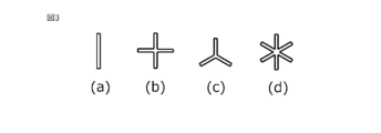
- FIG. 3 is a diagram illustrating the shape of a gas-liquid separation section of the foreign matter removal device according to the first embodiment.
- FIG. 7 is a diagram illustrating another mounting state of the gas-liquid separation section of the foreign matter removal device according to the first embodiment.
- the vertical direction means the up-down direction on the page
- the horizontal direction means the left-right direction on the page.
- FIG. 1 is an explanatory diagram schematically showing a foreign matter removing device 1 according to the first embodiment.
- FIG. 2 is a diagram of FIG. 1 viewed from the AA side.
- the foreign matter removal device 1 is installed in a circuit through which a fluid such as water flows.
- the foreign matter removal device 1 is a device that removes foreign matter contained in an inflowing fluid and causes the fluid to flow out. It includes a foreign matter discharging means 7, a second foreign matter discharging means 8, a second foreign matter discharging means connection section 9, a rectifying plate 10, a gas-liquid separation section 11, a support column 12, and the like.
- FIGS. 1 and 2 the direction of movement of the fluid flowing through the foreign matter removal device 1 is indicated by an arrow.
- the broken line shows the inner wall or the invisible part.
- the trap section 2 is a hollow cylindrical structure. When the foreign matter removal device 1 is installed in a circuit through which fluid flows, the trap section 2 is arranged to extend in the vertical direction, as illustrated in FIG.
- the trap part 2 may be made of metal such as stainless steel, brass, copper, aluminum, or steel, or may be made of polytetrafluoroethylene (Teflon (registered trademark) resin), polyvinyl chloride, polyethylene, polystyrene, polypropylene, polysulfone, isoprene.
- resin such as rubber, butadiene rubber, styrene-butadiene rubber, aromatic polyamide (such as nylon 6 or nylon 6-6), ABS (acrylonitrile-butadiene-styrene), acrylic, or carbon fiber reinforced plastic.
- the inflow section 3 constitutes a flow path for causing the fluid flowing in the circuit to flow into the trap section 2. As illustrated in FIG. 1, one end of the inflow section 3 is connected to the upper part of the trap section 2, and the other end of the inflow section 3 is connected to the circuit via piping, so that fluid flows from the circuit side in the direction of arrow B. invade.
- the outflow part 4 constitutes a flow path for causing the fluid flowing in the trap part 2 to flow out to a circuit outside the trap part 2. As illustrated in FIG. 1, one end of the outflow section 4 is connected to the trap section 2, and the other end of the outflow section 4 is connected to a circuit via piping. The internal fluid of the swirling flow flowing inside the cylindrical structure of the separation section 5, which will be described later, is caused to flow out to the circuit outside the trap section 2 via the outflow section 4.
- the inflow section 3 is configured so that the fluid flowing inside the inflow section 3 generates a swirling flow within the trap section 2, as illustrated in FIG. This configuration prevents the fluid that has flowed into the foreign matter removing device 1 from directly flowing out of the foreign matter removing device 1 from the outflow portion 4 .
- the fluid that has flowed into the trap section 2 from the inflow section 3 becomes a swirling flow that swirls inside the trap section 2 along the outer periphery of the trap section 2, which has a circular horizontal cross section as shown in FIG.
- the downward swirling flow flows out from the outflow portion 4.
- the separation section 5 is a separation member for separating the fluid flowing in from the inflow section 3 into the outer peripheral side and the center side within the trap section 2.
- the separation section 5 is a hollow cylindrical structure disposed at a predetermined position inside the trap section 2, separated from the outer periphery, and is a cylindrical member in this embodiment. Therefore, as shown in FIG. 2, the inner diameter of the separating section 5 is smaller than the inner diameter of the trap section 2 at the position where the separating section 5 is disposed. As a result, a gap (hereinafter referred to as the first foreign matter trapping part 6) is formed between the inner wall of the trap part 2 and the separation part 5. With this configuration, the fluid that has flowed into the foreign matter removal device 1 is separated in the trap section 2 into an inner swirling fluid flowing inside the separating section 5 and an outer swirling fluid flowing outside the separating section 5. be done.
- the separation section 5 is arranged below the trap section 2, as illustrated in FIG.
- the separation section 5 is disposed at the bottom of the trap section 2 and vertically below the inflow section 3 .
- the outflow section 4 is similarly arranged vertically below the inflow section 3.
- the separation part 5 is arranged at the same position in the vertical direction as the connection part of the trap part 2 to which the outflow part 4 is connected.
- the outflow portion 4 is formed to penetrate the cylindrical structure of the separation portion 5 and the trap portion 2 .
- the first foreign matter foreign matter having a higher specific gravity than the fluid, such as iron rust contained in the fluid (hereinafter referred to as the first foreign matter), is collected in the first foreign matter trapping part 6, and the inside where the first foreign matter has been removed is collected.
- the fluid flows out from the outlet 4.
- the fluid flows in a cyclone shape as a swirling flow within the trap section 2, thereby forming a vortex.
- the rotation associated with the vortex creates a centrifugal force that pushes the fluid outward. That is, the fluid inside the trap section 2 has a high pressure on the outside and a low pressure on the center side.
- foreign matter having a specific gravity smaller than the fluid hereinafter referred to as the second foreign matter
- bubbles gathers at or near the horizontal center (hereinafter referred to as the center part) within the trap section 2 due to this difference in pressure. It floats due to the difference in specific gravity with the fluid.
- the first foreign matter moves toward the outer periphery inside the trap section 2 due to such a difference in pressure, and collects at the lower part of the trap section 2 due to gravitational sedimentation.
- the first foreign matter will collect on the outside of the separation section 5 within the trap section 2. Therefore, the fluid from which not only the first foreign matter but also the second foreign matter has been appropriately removed is discharged from the outflow portion 4.
- the first foreign matter capturing section 6 that captures the first foreign matter, the first foreign matter that has settled due to gravity and has a large specific gravity is captured.
- the first foreign matter capturing section 6 is provided with a first foreign matter discharging means 7 extending vertically downward from the bottom of the trap section 2 .
- the first foreign matter discharging means 7 discharges the first foreign matter captured by the first foreign matter capturing section 6.
- the first foreign matter discharge means 7 is, for example, a valve, and when opened, discharges the first foreign matter captured by the first foreign matter trap 6 to the outside.
- the second foreign matter discharging means 8 discharges the second foreign matter that collects at the center of the trap section 2.
- the second foreign matter discharging means 8 is, for example, an air valve, and when opened, discharges the second foreign matter that collects at the center of the trap section 2 and floats to the outside.
- the second foreign matter discharging means connection section 9 connects the second foreign matter discharging means 8 to the trap section 2.
- the second foreign matter discharge means connecting part 9 is located at the top of the inner wall at the center of the trap part 2, which is vertically above the outflow part 4 and above the inflow part 3. It is a space that opens upward from the ceiling. With this configuration, the second foreign matter that gathers at the center of the trap section 2 and floats up flows into the second foreign matter discharge means connection section 9 and floats to the second foreign matter discharge means 8.
- the rectifying plate 10 is disposed at the second foreign matter discharge means connection portion 9 and floats the second foreign matter that has flowed into the second foreign matter discharge means connection portion 9.
- the current plate 10 has a shape that divides the opening of the second foreign matter ejecting means connecting portion 9
- the rectifying plate 10 has a shape that divides the opening of the second foreign matter ejecting means connecting portion 9. It is possible to reduce the swirling flow and float the second foreign matter that has flowed into the second foreign matter discharging means connection portion 9 to the second foreign matter discharging means 8.
- the second foreign matter discharging means connection portion 9 and the rectifying plate 10 can suppress malfunction of the second foreign matter discharging means 8 due to the downward swirling flow generated in the center of the trap portion 2 .
- the gas-liquid separation section 11 is a member for suppressing the downward swirling flow generated in the center of the trap section 2.
- the gas-liquid separation section 11 is disposed inside the trap section 2 and below the inflow section 3, and is supported by a column 12 that is a rod-shaped member, and the column 12 is fixed to the bottom of the trap section 2. There is.
- the gas-liquid separation section 11 is desirably arranged in the downward direction of the second foreign matter that collects in the center of the trap section 2, and the separation section is located on a central axis C connecting the centers of both bottom surfaces of the cylindrical trap section 2. It is located within 5.
- the outflow portion 4 and the second foreign matter discharge means connection portion 9 are also arranged on the same central axis C, and are arranged on concentric circles as shown in FIG. 2.
- the gas-liquid separation section 11 is a circular plate-like member, but the horizontal cross-section (perpendicular to the central axis C) is shown in FIGS. As shown, a circular or polygonal plate member may be used. Further, the area in the horizontal cross section may be smaller than the outflow portion 4 . If the area is smaller than the outflow portion 4, the effect of suppressing the downward swirling flow will be reduced, but the pressure loss of the foreign matter removal device 1 can be reduced. As shown in FIG. 1, the plate-like member of the gas-liquid separation section 11 extends in a direction perpendicular to the direction of outflow from the outflow section 4. As shown in FIG.
- the gas-liquid separator 11 arranged in this manner allows second foreign matter that flows into the trap section 2 from the inflow section 3 and collects at the center of the trap section 2 to move toward the outflow section 4 by a downward swirling flow.
- the second foreign matter is suppressed and retained within the trap section 2, and the second foreign matter is promoted to float toward the second foreign matter discharge means 8.
- the gas-liquid separation section 11 is supported by a column 12 fixed to the bottom of the trap section 2, but as shown in FIG. It may be supported by Further, the separating portion 5 may be supported from the side surface by a support. Further, when the gas-liquid separation section 11 is disposed inside the separation section 5, the effect of suppressing the downward swirling flow toward the outflow section 4 is greater than when the gas-liquid separation section 11 is disposed outside the separation section 5.
- the foreign matter removal device As described above, according to the foreign matter removal device according to the present embodiment, it is possible to remove foreign matter with a large specific gravity such as iron rust, which is the first foreign matter, while the second foreign matter, such as air bubbles, can be removed using the fluid. Furthermore, the ability to remove foreign matter having a specific gravity lower than that of the fluid can be further improved.
Landscapes
- Chemical & Material Sciences (AREA)
- Chemical Kinetics & Catalysis (AREA)
- Physics & Mathematics (AREA)
- General Engineering & Computer Science (AREA)
- Engineering & Computer Science (AREA)
- Geometry (AREA)
- Fluid Mechanics (AREA)
- Toxicology (AREA)
- Health & Medical Sciences (AREA)
- Mechanical Engineering (AREA)
- Cyclones (AREA)
- Degasification And Air Bubble Elimination (AREA)
- Separating Particles In Gases By Inertia (AREA)
Priority Applications (5)
| Application Number | Priority Date | Filing Date | Title |
|---|---|---|---|
| JP2022565792A JP7351023B1 (ja) | 2022-07-13 | 2022-07-13 | 異物除去装置 |
| US18/992,443 US12551905B2 (en) | 2022-07-13 | 2022-07-13 | Foreign matter removal device |
| PCT/JP2022/027574 WO2024013885A1 (ja) | 2022-07-13 | 2022-07-13 | 異物除去装置 |
| EP22951099.5A EP4512502A4 (en) | 2022-07-13 | 2022-07-13 | FOREIGN MATERIAL REMOVAL DEVICE |
| CN202280097638.4A CN119451753A (zh) | 2022-07-13 | 2022-07-13 | 异物除去装置 |
Applications Claiming Priority (1)
| Application Number | Priority Date | Filing Date | Title |
|---|---|---|---|
| PCT/JP2022/027574 WO2024013885A1 (ja) | 2022-07-13 | 2022-07-13 | 異物除去装置 |
Publications (1)
| Publication Number | Publication Date |
|---|---|
| WO2024013885A1 true WO2024013885A1 (ja) | 2024-01-18 |
Family
ID=88099137
Family Applications (1)
| Application Number | Title | Priority Date | Filing Date |
|---|---|---|---|
| PCT/JP2022/027574 Ceased WO2024013885A1 (ja) | 2022-07-13 | 2022-07-13 | 異物除去装置 |
Country Status (5)
| Country | Link |
|---|---|
| US (1) | US12551905B2 (https=) |
| EP (1) | EP4512502A4 (https=) |
| JP (1) | JP7351023B1 (https=) |
| CN (1) | CN119451753A (https=) |
| WO (1) | WO2024013885A1 (https=) |
Cited By (1)
| Publication number | Priority date | Publication date | Assignee | Title |
|---|---|---|---|---|
| JP7607844B1 (ja) * | 2024-04-03 | 2024-12-27 | 三菱電機株式会社 | 気液分離装置 |
Citations (7)
| Publication number | Priority date | Publication date | Assignee | Title |
|---|---|---|---|---|
| JPS5673567A (en) * | 1979-11-19 | 1981-06-18 | Tokico Ltd | Gas-liquid separator |
| JPS62156382A (ja) * | 1985-12-27 | 1987-07-11 | 株式会社 サトミ製作所 | 渦流式除塵機 |
| JPS63224753A (ja) * | 1987-03-13 | 1988-09-19 | Mitsui Toatsu Chem Inc | 混合物の分離方法 |
| JPH0245105U (https=) * | 1988-09-22 | 1990-03-28 | ||
| JPH04240288A (ja) * | 1990-08-28 | 1992-08-27 | Kamyr Inc | ハイドロサイクロン及び液体スラリー成分分離装置 |
| JP2000312840A (ja) * | 1999-04-28 | 2000-11-14 | Gijutsu Kaihatsu Sogo Kenkyusho:Kk | 混合流体における重質成分及び軽質成分の分離装置 |
| JP2007187141A (ja) * | 2006-01-16 | 2007-07-26 | Toyota Boshoku Corp | 気泡分離器 |
Family Cites Families (17)
| Publication number | Priority date | Publication date | Assignee | Title |
|---|---|---|---|---|
| NL181479C (https=) * | 1952-09-24 | |||
| EP0024148B1 (en) * | 1979-08-09 | 1985-02-13 | The British Petroleum Company p.l.c. | Separator for oil, gas and water |
| JPS56168849A (en) * | 1980-06-02 | 1981-12-25 | Sumitomo Heavy Ind Ltd | Cyclone type preheating device for pulverized and granular bodies |
| DE4309920A1 (en) * | 1993-03-26 | 1993-08-26 | Voith Gmbh J M | Hydro-cyclone separator with central outlet tube for lighter fraction - which has internal guide vanes at a distance from end equal to half diameter of tube. |
| JPH11123303A (ja) * | 1997-10-21 | 1999-05-11 | Shinyuu Giken:Kk | 気泡分離装置 |
| NL1012245C2 (nl) * | 1999-06-04 | 2000-12-06 | Spark Technologies And Innovat | Inrichting en werkwijze voor het verwerken van een mengsel van gas met vloeistof en/of vaste stof. |
| US7288138B2 (en) | 2004-11-22 | 2007-10-30 | Eaton Corporation | Three-phase cyclonic fluid separator |
| JP4628252B2 (ja) | 2005-11-02 | 2011-02-09 | 株式会社日立エンジニアリング・アンド・サービス | 水中軸受装置の潤滑システム |
| CA2724171A1 (en) * | 2008-05-15 | 2009-11-19 | Outotec Oyj | Apparatus and method for mechanical deaeration |
| DE102009016045A1 (de) * | 2009-04-02 | 2010-10-07 | Linde Aktiengesellschaft | Strömungsleitvorrichtung für ein Tauchrohr eines Zyklonabscheiders |
| MX2011011068A (es) * | 2009-04-20 | 2012-02-21 | Sorbwater Technology As | Aparato y metodo para separacion de fases en un flujo multifásico. |
| CN201519621U (zh) * | 2009-10-20 | 2010-07-07 | 大庆石油学院 | 气液固三相分离水力旋流器 |
| US20140251140A1 (en) | 2013-03-06 | 2014-09-11 | Cameron Solutions, Inc. | Methods To Reduce Gas Carry-Under For Cyclonic Separators |
| CN203916929U (zh) * | 2014-04-28 | 2014-11-05 | 深圳科力迩科技有限公司 | 一种旋流式多相分离器 |
| CN110251998B (zh) * | 2019-06-21 | 2021-02-09 | 燕山大学 | 分流过滤式气液固三相旋流分离装置 |
| JP2024168849A (ja) * | 2023-05-25 | 2024-12-05 | 能美防災株式会社 | 消火装置 |
| JP2025168849A (ja) * | 2024-04-30 | 2025-11-12 | Toppanホールディングス株式会社 | 調光シート用積層体、および調光シート用積層体の製造方法 |
-
2022
- 2022-07-13 JP JP2022565792A patent/JP7351023B1/ja active Active
- 2022-07-13 EP EP22951099.5A patent/EP4512502A4/en active Pending
- 2022-07-13 CN CN202280097638.4A patent/CN119451753A/zh active Pending
- 2022-07-13 WO PCT/JP2022/027574 patent/WO2024013885A1/ja not_active Ceased
- 2022-07-13 US US18/992,443 patent/US12551905B2/en active Active
Patent Citations (7)
| Publication number | Priority date | Publication date | Assignee | Title |
|---|---|---|---|---|
| JPS5673567A (en) * | 1979-11-19 | 1981-06-18 | Tokico Ltd | Gas-liquid separator |
| JPS62156382A (ja) * | 1985-12-27 | 1987-07-11 | 株式会社 サトミ製作所 | 渦流式除塵機 |
| JPS63224753A (ja) * | 1987-03-13 | 1988-09-19 | Mitsui Toatsu Chem Inc | 混合物の分離方法 |
| JPH0245105U (https=) * | 1988-09-22 | 1990-03-28 | ||
| JPH04240288A (ja) * | 1990-08-28 | 1992-08-27 | Kamyr Inc | ハイドロサイクロン及び液体スラリー成分分離装置 |
| JP2000312840A (ja) * | 1999-04-28 | 2000-11-14 | Gijutsu Kaihatsu Sogo Kenkyusho:Kk | 混合流体における重質成分及び軽質成分の分離装置 |
| JP2007187141A (ja) * | 2006-01-16 | 2007-07-26 | Toyota Boshoku Corp | 気泡分離器 |
Non-Patent Citations (1)
| Title |
|---|
| See also references of EP4512502A4 * |
Cited By (2)
| Publication number | Priority date | Publication date | Assignee | Title |
|---|---|---|---|---|
| JP7607844B1 (ja) * | 2024-04-03 | 2024-12-27 | 三菱電機株式会社 | 気液分離装置 |
| WO2025210783A1 (ja) * | 2024-04-03 | 2025-10-09 | 三菱電機株式会社 | 気液分離装置 |
Also Published As
| Publication number | Publication date |
|---|---|
| CN119451753A (zh) | 2025-02-14 |
| US12551905B2 (en) | 2026-02-17 |
| EP4512502A1 (en) | 2025-02-26 |
| EP4512502A4 (en) | 2025-07-23 |
| JP7351023B1 (ja) | 2023-09-26 |
| US20250256291A1 (en) | 2025-08-14 |
| JPWO2024013885A1 (https=) | 2024-01-18 |
Similar Documents
| Publication | Publication Date | Title |
|---|---|---|
| RU2608772C2 (ru) | Центробежный циклонный сепаратор | |
| EP2271432B1 (en) | Particle separator | |
| US10413853B2 (en) | Gas-liquid separator | |
| JP5439026B2 (ja) | 気液分離器 | |
| WO2013124622A1 (en) | Fluid separator | |
| JP7351023B1 (ja) | 異物除去装置 | |
| JP2013044456A (ja) | 油分離器及び冷凍サイクル装置 | |
| JP2020509344A (ja) | 排気測定装置用凝縮水分離機 | |
| EP3229933B1 (en) | Separator and method | |
| JP5803263B2 (ja) | 気液分離器 | |
| JP7186936B1 (ja) | 異物除去装置 | |
| JP4497336B2 (ja) | サイクロン式オイルミスト除去装置 | |
| JP4932333B2 (ja) | 消泡装置 | |
| WO2015037722A1 (ja) | 浮上油吸引装置及び分離槽 | |
| KR100908883B1 (ko) | 압축공기용 수분분리기 | |
| US4643746A (en) | Apparatus for separating gas from fluid | |
| JP7317153B1 (ja) | 異物除去装置 | |
| CN110812943B (zh) | 一种过滤结构、前置过滤器及过滤方法 | |
| JP6042161B2 (ja) | 固液分離装置 | |
| JP5070356B1 (ja) | 空気吹出し手段用の気液分離装置 | |
| JPWO2024013885A5 (https=) | ||
| KR101652375B1 (ko) | 유정유체 분리장치 | |
| KR101847018B1 (ko) | 열교환기능을 갖는 생산수 처리장치 | |
| JP2007253048A (ja) | 防泡装置及びサイクロン型濾過装置 | |
| CN207072927U (zh) | 一种钻井用的高效四相分离器 |
Legal Events
| Date | Code | Title | Description |
|---|---|---|---|
| WWE | Wipo information: entry into national phase |
Ref document number: 2022565792 Country of ref document: JP |
|
| 121 | Ep: the epo has been informed by wipo that ep was designated in this application |
Ref document number: 22951099 Country of ref document: EP Kind code of ref document: A1 |
|
| WWE | Wipo information: entry into national phase |
Ref document number: 2022951099 Country of ref document: EP |
|
| ENP | Entry into the national phase |
Ref document number: 2022951099 Country of ref document: EP Effective date: 20241121 |
|
| WWE | Wipo information: entry into national phase |
Ref document number: 202280097638.4 Country of ref document: CN |
|
| WWE | Wipo information: entry into national phase |
Ref document number: 18992443 Country of ref document: US |
|
| NENP | Non-entry into the national phase |
Ref country code: DE |
|
| WWP | Wipo information: published in national office |
Ref document number: 202280097638.4 Country of ref document: CN |
|
| WWP | Wipo information: published in national office |
Ref document number: 18992443 Country of ref document: US |
|
| WWG | Wipo information: grant in national office |
Ref document number: 18992443 Country of ref document: US |