WO2024013885A1 - Foreign matter removal device - Google Patents
Foreign matter removal device Download PDFInfo
- Publication number
- WO2024013885A1 WO2024013885A1 PCT/JP2022/027574 JP2022027574W WO2024013885A1 WO 2024013885 A1 WO2024013885 A1 WO 2024013885A1 JP 2022027574 W JP2022027574 W JP 2022027574W WO 2024013885 A1 WO2024013885 A1 WO 2024013885A1
- Authority
- WO
- WIPO (PCT)
- Prior art keywords
- section
- foreign matter
- trap
- fluid
- removal device
- Prior art date
Links
- 239000012530 fluid Substances 0.000 claims abstract description 70
- 238000000926 separation method Methods 0.000 claims abstract description 44
- 238000007599 discharging Methods 0.000 claims abstract description 21
- 239000007788 liquid Substances 0.000 claims abstract description 21
- 230000005484 gravity Effects 0.000 claims abstract description 20
- 239000000126 substance Substances 0.000 claims description 5
- 230000000717 retained effect Effects 0.000 claims description 2
- XEEYBQQBJWHFJM-UHFFFAOYSA-N Iron Chemical compound [Fe] XEEYBQQBJWHFJM-UHFFFAOYSA-N 0.000 description 24
- 229910052742 iron Inorganic materials 0.000 description 12
- XLYOFNOQVPJJNP-UHFFFAOYSA-N water Substances O XLYOFNOQVPJJNP-UHFFFAOYSA-N 0.000 description 9
- JEIPFZHSYJVQDO-UHFFFAOYSA-N iron(III) oxide Inorganic materials O=[Fe]O[Fe]=O JEIPFZHSYJVQDO-UHFFFAOYSA-N 0.000 description 8
- 238000010586 diagram Methods 0.000 description 7
- 238000010438 heat treatment Methods 0.000 description 3
- -1 polytetrafluoroethylene Polymers 0.000 description 3
- RRHGJUQNOFWUDK-UHFFFAOYSA-N Isoprene Chemical compound CC(=C)C=C RRHGJUQNOFWUDK-UHFFFAOYSA-N 0.000 description 2
- XECAHXYUAAWDEL-UHFFFAOYSA-N acrylonitrile butadiene styrene Chemical compound C=CC=C.C=CC#N.C=CC1=CC=CC=C1 XECAHXYUAAWDEL-UHFFFAOYSA-N 0.000 description 2
- 239000004676 acrylonitrile butadiene styrene Substances 0.000 description 2
- 229920000122 acrylonitrile butadiene styrene Polymers 0.000 description 2
- 230000000694 effects Effects 0.000 description 2
- 239000011347 resin Substances 0.000 description 2
- 229920005989 resin Polymers 0.000 description 2
- 229920002972 Acrylic fiber Polymers 0.000 description 1
- 229910001369 Brass Inorganic materials 0.000 description 1
- RYGMFSIKBFXOCR-UHFFFAOYSA-N Copper Chemical compound [Cu] RYGMFSIKBFXOCR-UHFFFAOYSA-N 0.000 description 1
- 229920002292 Nylon 6 Polymers 0.000 description 1
- 229920002302 Nylon 6,6 Polymers 0.000 description 1
- 239000005062 Polybutadiene Substances 0.000 description 1
- 239000004698 Polyethylene Substances 0.000 description 1
- 239000004743 Polypropylene Substances 0.000 description 1
- 239000004793 Polystyrene Substances 0.000 description 1
- 229910000831 Steel Inorganic materials 0.000 description 1
- 239000004809 Teflon Substances 0.000 description 1
- 229920006362 Teflon® Polymers 0.000 description 1
- NIXOWILDQLNWCW-UHFFFAOYSA-N acrylic acid group Chemical group C(C=C)(=O)O NIXOWILDQLNWCW-UHFFFAOYSA-N 0.000 description 1
- 229910052782 aluminium Inorganic materials 0.000 description 1
- XAGFODPZIPBFFR-UHFFFAOYSA-N aluminium Chemical compound [Al] XAGFODPZIPBFFR-UHFFFAOYSA-N 0.000 description 1
- 239000004760 aramid Substances 0.000 description 1
- 229920003235 aromatic polyamide Polymers 0.000 description 1
- 239000010951 brass Substances 0.000 description 1
- 239000004918 carbon fiber reinforced polymer Substances 0.000 description 1
- 229910052802 copper Inorganic materials 0.000 description 1
- 239000010949 copper Substances 0.000 description 1
- 230000007797 corrosion Effects 0.000 description 1
- 238000005260 corrosion Methods 0.000 description 1
- 229920001971 elastomer Polymers 0.000 description 1
- 238000005516 engineering process Methods 0.000 description 1
- 238000012388 gravitational sedimentation Methods 0.000 description 1
- 230000007257 malfunction Effects 0.000 description 1
- 229910052751 metal Inorganic materials 0.000 description 1
- 239000002184 metal Substances 0.000 description 1
- 230000002093 peripheral effect Effects 0.000 description 1
- 229920002492 poly(sulfone) Polymers 0.000 description 1
- 229920002857 polybutadiene Polymers 0.000 description 1
- 229920000573 polyethylene Polymers 0.000 description 1
- 229920001155 polypropylene Polymers 0.000 description 1
- 229920002223 polystyrene Polymers 0.000 description 1
- 229920001343 polytetrafluoroethylene Polymers 0.000 description 1
- 239000004810 polytetrafluoroethylene Substances 0.000 description 1
- 239000004800 polyvinyl chloride Substances 0.000 description 1
- 229920000915 polyvinyl chloride Polymers 0.000 description 1
- 239000005060 rubber Substances 0.000 description 1
- 150000003839 salts Chemical class 0.000 description 1
- 238000004062 sedimentation Methods 0.000 description 1
- 229910001220 stainless steel Inorganic materials 0.000 description 1
- 239000010935 stainless steel Substances 0.000 description 1
- 239000010959 steel Substances 0.000 description 1
- 229920003048 styrene butadiene rubber Polymers 0.000 description 1
- 108010063955 thrombin receptor peptide (42-47) Proteins 0.000 description 1
Images


Classifications
-
- B—PERFORMING OPERATIONS; TRANSPORTING
- B01—PHYSICAL OR CHEMICAL PROCESSES OR APPARATUS IN GENERAL
- B01D—SEPARATION
- B01D19/00—Degasification of liquids
-
- B—PERFORMING OPERATIONS; TRANSPORTING
- B03—SEPARATION OF SOLID MATERIALS USING LIQUIDS OR USING PNEUMATIC TABLES OR JIGS; MAGNETIC OR ELECTROSTATIC SEPARATION OF SOLID MATERIALS FROM SOLID MATERIALS OR FLUIDS; SEPARATION BY HIGH-VOLTAGE ELECTRIC FIELDS
- B03B—SEPARATING SOLID MATERIALS USING LIQUIDS OR USING PNEUMATIC TABLES OR JIGS
- B03B5/00—Washing granular, powdered or lumpy materials; Wet separating
- B03B5/28—Washing granular, powdered or lumpy materials; Wet separating by sink-float separation
-
- B—PERFORMING OPERATIONS; TRANSPORTING
- B04—CENTRIFUGAL APPARATUS OR MACHINES FOR CARRYING-OUT PHYSICAL OR CHEMICAL PROCESSES
- B04C—APPARATUS USING FREE VORTEX FLOW, e.g. CYCLONES
- B04C3/00—Apparatus in which the axial direction of the vortex flow following a screw-thread type line remains unchanged ; Devices in which one of the two discharge ducts returns centrally through the vortex chamber, a reverse-flow vortex being prevented by bulkheads in the central discharge duct
-
- B—PERFORMING OPERATIONS; TRANSPORTING
- B04—CENTRIFUGAL APPARATUS OR MACHINES FOR CARRYING-OUT PHYSICAL OR CHEMICAL PROCESSES
- B04C—APPARATUS USING FREE VORTEX FLOW, e.g. CYCLONES
- B04C5/00—Apparatus in which the axial direction of the vortex is reversed
- B04C5/08—Vortex chamber constructions
- B04C5/081—Shapes or dimensions
-
- F—MECHANICAL ENGINEERING; LIGHTING; HEATING; WEAPONS; BLASTING
- F16—ENGINEERING ELEMENTS AND UNITS; GENERAL MEASURES FOR PRODUCING AND MAINTAINING EFFECTIVE FUNCTIONING OF MACHINES OR INSTALLATIONS; THERMAL INSULATION IN GENERAL
- F16L—PIPES; JOINTS OR FITTINGS FOR PIPES; SUPPORTS FOR PIPES, CABLES OR PROTECTIVE TUBING; MEANS FOR THERMAL INSULATION IN GENERAL
- F16L55/00—Devices or appurtenances for use in, or in connection with, pipes or pipe systems
- F16L55/24—Preventing accumulation of dirt or other matter in the pipes, e.g. by traps, by strainers
Definitions
- This application relates to a foreign matter removal device.
- Patent Document 1 There is a known foreign matter removal device that uses swirling flow and gravity sedimentation to remove foreign matter contained in fluid in piping (for example, see Patent Document 1).
- This foreign matter removal device removes foreign matter such as iron rust, insoluble salts, and corrosion products that may be contained in a fluid such as water flowing inside a pipe, and contributes to suppressing damage inside the pipe.
- the foreign matter removal device is used, for example, in a heat pump hot water supply and heating system that has a circulating water circuit that uses iron radiators, iron piping, and the like.
- Iron radiators, iron pipes, and the like in the circulating water circuit can generate foreign substances such as iron rust in the fluid in the circulating water circuit. Therefore, conventional foreign matter removal devices are used to remove foreign matter, such as iron rust, which has a higher specific gravity than the fluid.
- the present application was made in view of the above circumstances, and while it is possible to remove foreign substances such as iron rust that have a higher specific gravity than fluids, it also has the ability to remove foreign substances such as air bubbles that have a lower specific gravity than fluids.
- the purpose of the present invention is to provide a foreign matter removal device with improved performance.
- the foreign matter removal device disclosed in this application includes: Foreign matter contained in the fluid in the pipe is removed using swirling flow in a cylindrical trap part, an inflow section that allows fluid to flow into the trap section;
- the trap part is disposed at the bottom and has a cylindrical structure, and the fluid flowing in from the inflow part is divided into an inner fluid of a swirling flow flowing inside the cylindrical structure and an outer fluid of the swirling flow flowing outside the cylindrical structure.
- a separation section that separates into an outflow section that allows the inner fluid separated by the separation section to flow out from within the trap section; a rectifying plate disposed in the center of the trap section and above the inflow section; a gas-liquid separation section that is disposed in the center of the trap section and below the inflow section and suppresses the flow of the swirling flow toward the outflow section; It is characterized by having the following.
- the foreign matter removal device it is possible to remove foreign matter such as iron rust, which has a higher specific gravity than the fluid, while improving the ability to remove foreign matter such as bubbles, which have a lower specific gravity than the fluid.
- FIG. 1 is an explanatory diagram schematically showing a foreign matter removing device according to a first embodiment
- FIG. 2 is a diagram showing the arrangement of each component when FIG. 1 is viewed from the AA side.
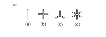
- FIG. 3 is a diagram showing the shape of a current plate of the foreign matter removing device according to the first embodiment.
- FIG. 3 is a diagram illustrating the shape of a gas-liquid separation section of the foreign matter removal device according to the first embodiment.
- FIG. 7 is a diagram illustrating another mounting state of the gas-liquid separation section of the foreign matter removal device according to the first embodiment.
- the vertical direction means the up-down direction on the page
- the horizontal direction means the left-right direction on the page.
- FIG. 1 is an explanatory diagram schematically showing a foreign matter removing device 1 according to the first embodiment.
- FIG. 2 is a diagram of FIG. 1 viewed from the AA side.
- the foreign matter removal device 1 is installed in a circuit through which a fluid such as water flows.
- the foreign matter removal device 1 is a device that removes foreign matter contained in an inflowing fluid and causes the fluid to flow out. It includes a foreign matter discharging means 7, a second foreign matter discharging means 8, a second foreign matter discharging means connection section 9, a rectifying plate 10, a gas-liquid separation section 11, a support column 12, and the like.
- FIGS. 1 and 2 the direction of movement of the fluid flowing through the foreign matter removal device 1 is indicated by an arrow.
- the broken line shows the inner wall or the invisible part.
- the trap section 2 is a hollow cylindrical structure. When the foreign matter removal device 1 is installed in a circuit through which fluid flows, the trap section 2 is arranged to extend in the vertical direction, as illustrated in FIG.
- the trap part 2 may be made of metal such as stainless steel, brass, copper, aluminum, or steel, or may be made of polytetrafluoroethylene (Teflon (registered trademark) resin), polyvinyl chloride, polyethylene, polystyrene, polypropylene, polysulfone, isoprene.
- resin such as rubber, butadiene rubber, styrene-butadiene rubber, aromatic polyamide (such as nylon 6 or nylon 6-6), ABS (acrylonitrile-butadiene-styrene), acrylic, or carbon fiber reinforced plastic.
- the inflow section 3 constitutes a flow path for causing the fluid flowing in the circuit to flow into the trap section 2. As illustrated in FIG. 1, one end of the inflow section 3 is connected to the upper part of the trap section 2, and the other end of the inflow section 3 is connected to the circuit via piping, so that fluid flows from the circuit side in the direction of arrow B. invade.
- the outflow part 4 constitutes a flow path for causing the fluid flowing in the trap part 2 to flow out to a circuit outside the trap part 2. As illustrated in FIG. 1, one end of the outflow section 4 is connected to the trap section 2, and the other end of the outflow section 4 is connected to a circuit via piping. The internal fluid of the swirling flow flowing inside the cylindrical structure of the separation section 5, which will be described later, is caused to flow out to the circuit outside the trap section 2 via the outflow section 4.
- the inflow section 3 is configured so that the fluid flowing inside the inflow section 3 generates a swirling flow within the trap section 2, as illustrated in FIG. This configuration prevents the fluid that has flowed into the foreign matter removing device 1 from directly flowing out of the foreign matter removing device 1 from the outflow portion 4 .
- the fluid that has flowed into the trap section 2 from the inflow section 3 becomes a swirling flow that swirls inside the trap section 2 along the outer periphery of the trap section 2, which has a circular horizontal cross section as shown in FIG.
- the downward swirling flow flows out from the outflow portion 4.
- the separation section 5 is a separation member for separating the fluid flowing in from the inflow section 3 into the outer peripheral side and the center side within the trap section 2.
- the separation section 5 is a hollow cylindrical structure disposed at a predetermined position inside the trap section 2, separated from the outer periphery, and is a cylindrical member in this embodiment. Therefore, as shown in FIG. 2, the inner diameter of the separating section 5 is smaller than the inner diameter of the trap section 2 at the position where the separating section 5 is disposed. As a result, a gap (hereinafter referred to as the first foreign matter trapping part 6) is formed between the inner wall of the trap part 2 and the separation part 5. With this configuration, the fluid that has flowed into the foreign matter removal device 1 is separated in the trap section 2 into an inner swirling fluid flowing inside the separating section 5 and an outer swirling fluid flowing outside the separating section 5. be done.
- the separation section 5 is arranged below the trap section 2, as illustrated in FIG.
- the separation section 5 is disposed at the bottom of the trap section 2 and vertically below the inflow section 3 .
- the outflow section 4 is similarly arranged vertically below the inflow section 3.
- the separation part 5 is arranged at the same position in the vertical direction as the connection part of the trap part 2 to which the outflow part 4 is connected.
- the outflow portion 4 is formed to penetrate the cylindrical structure of the separation portion 5 and the trap portion 2 .
- the first foreign matter foreign matter having a higher specific gravity than the fluid, such as iron rust contained in the fluid (hereinafter referred to as the first foreign matter), is collected in the first foreign matter trapping part 6, and the inside where the first foreign matter has been removed is collected.
- the fluid flows out from the outlet 4.
- the fluid flows in a cyclone shape as a swirling flow within the trap section 2, thereby forming a vortex.
- the rotation associated with the vortex creates a centrifugal force that pushes the fluid outward. That is, the fluid inside the trap section 2 has a high pressure on the outside and a low pressure on the center side.
- foreign matter having a specific gravity smaller than the fluid hereinafter referred to as the second foreign matter
- bubbles gathers at or near the horizontal center (hereinafter referred to as the center part) within the trap section 2 due to this difference in pressure. It floats due to the difference in specific gravity with the fluid.
- the first foreign matter moves toward the outer periphery inside the trap section 2 due to such a difference in pressure, and collects at the lower part of the trap section 2 due to gravitational sedimentation.
- the first foreign matter will collect on the outside of the separation section 5 within the trap section 2. Therefore, the fluid from which not only the first foreign matter but also the second foreign matter has been appropriately removed is discharged from the outflow portion 4.
- the first foreign matter capturing section 6 that captures the first foreign matter, the first foreign matter that has settled due to gravity and has a large specific gravity is captured.
- the first foreign matter capturing section 6 is provided with a first foreign matter discharging means 7 extending vertically downward from the bottom of the trap section 2 .
- the first foreign matter discharging means 7 discharges the first foreign matter captured by the first foreign matter capturing section 6.
- the first foreign matter discharge means 7 is, for example, a valve, and when opened, discharges the first foreign matter captured by the first foreign matter trap 6 to the outside.
- the second foreign matter discharging means 8 discharges the second foreign matter that collects at the center of the trap section 2.
- the second foreign matter discharging means 8 is, for example, an air valve, and when opened, discharges the second foreign matter that collects at the center of the trap section 2 and floats to the outside.
- the second foreign matter discharging means connection section 9 connects the second foreign matter discharging means 8 to the trap section 2.
- the second foreign matter discharge means connecting part 9 is located at the top of the inner wall at the center of the trap part 2, which is vertically above the outflow part 4 and above the inflow part 3. It is a space that opens upward from the ceiling. With this configuration, the second foreign matter that gathers at the center of the trap section 2 and floats up flows into the second foreign matter discharge means connection section 9 and floats to the second foreign matter discharge means 8.
- the rectifying plate 10 is disposed at the second foreign matter discharge means connection portion 9 and floats the second foreign matter that has flowed into the second foreign matter discharge means connection portion 9.
- the current plate 10 has a shape that divides the opening of the second foreign matter ejecting means connecting portion 9
- the rectifying plate 10 has a shape that divides the opening of the second foreign matter ejecting means connecting portion 9. It is possible to reduce the swirling flow and float the second foreign matter that has flowed into the second foreign matter discharging means connection portion 9 to the second foreign matter discharging means 8.
- the second foreign matter discharging means connection portion 9 and the rectifying plate 10 can suppress malfunction of the second foreign matter discharging means 8 due to the downward swirling flow generated in the center of the trap portion 2 .
- the gas-liquid separation section 11 is a member for suppressing the downward swirling flow generated in the center of the trap section 2.
- the gas-liquid separation section 11 is disposed inside the trap section 2 and below the inflow section 3, and is supported by a column 12 that is a rod-shaped member, and the column 12 is fixed to the bottom of the trap section 2. There is.
- the gas-liquid separation section 11 is desirably arranged in the downward direction of the second foreign matter that collects in the center of the trap section 2, and the separation section is located on a central axis C connecting the centers of both bottom surfaces of the cylindrical trap section 2. It is located within 5.
- the outflow portion 4 and the second foreign matter discharge means connection portion 9 are also arranged on the same central axis C, and are arranged on concentric circles as shown in FIG. 2.
- the gas-liquid separation section 11 is a circular plate-like member, but the horizontal cross-section (perpendicular to the central axis C) is shown in FIGS. As shown, a circular or polygonal plate member may be used. Further, the area in the horizontal cross section may be smaller than the outflow portion 4 . If the area is smaller than the outflow portion 4, the effect of suppressing the downward swirling flow will be reduced, but the pressure loss of the foreign matter removal device 1 can be reduced. As shown in FIG. 1, the plate-like member of the gas-liquid separation section 11 extends in a direction perpendicular to the direction of outflow from the outflow section 4. As shown in FIG.
- the gas-liquid separator 11 arranged in this manner allows second foreign matter that flows into the trap section 2 from the inflow section 3 and collects at the center of the trap section 2 to move toward the outflow section 4 by a downward swirling flow.
- the second foreign matter is suppressed and retained within the trap section 2, and the second foreign matter is promoted to float toward the second foreign matter discharge means 8.
- the gas-liquid separation section 11 is supported by a column 12 fixed to the bottom of the trap section 2, but as shown in FIG. It may be supported by Further, the separating portion 5 may be supported from the side surface by a support. Further, when the gas-liquid separation section 11 is disposed inside the separation section 5, the effect of suppressing the downward swirling flow toward the outflow section 4 is greater than when the gas-liquid separation section 11 is disposed outside the separation section 5.
- the foreign matter removal device As described above, according to the foreign matter removal device according to the present embodiment, it is possible to remove foreign matter with a large specific gravity such as iron rust, which is the first foreign matter, while the second foreign matter, such as air bubbles, can be removed using the fluid. Furthermore, the ability to remove foreign matter having a specific gravity lower than that of the fluid can be further improved.
Landscapes
- Engineering & Computer Science (AREA)
- General Engineering & Computer Science (AREA)
- Physics & Mathematics (AREA)
- Geometry (AREA)
- Mechanical Engineering (AREA)
- Chemical & Material Sciences (AREA)
- Chemical Kinetics & Catalysis (AREA)
- Separating Particles In Gases By Inertia (AREA)
Abstract
In a foreign matter removal device (1) that removes foreign matter contained in a fluid within piping by using a swirling flow generated within a trap section (2), the fluid is caused to flow into the trap section (2) and is separated into an inner fluid that flows inside a separation section (5) and an outer fluid that flows outside the separation section (5). First foreign matter, which has a higher specific gravity than the fluid contained in the outer fluid, is captured in a gap between the inner wall of the trap section (2) and the separation section (5), and second foreign matter, which has a lower specific gravity than the fluid contained in the inner fluid, is discharged to the outside from a foreign matter discharging means (8) via a foreign matter discharging means connection part (9) provided to the ceiling of the trap section (2) at a location vertically above the center of the trap section (2), separation of the second foreign matter being promoted by a gas-liquid separation unit (11).
Description
本願は、異物除去装置に関するものである。
This application relates to a foreign matter removal device.
配管内の流体に含まれる異物を除去する際に、旋回流と重力沈降とを利用して異物除去を行う異物除去装置が知られている(例えば、特許文献1参照)。この異物除去装置は、例えば、配管内に流れる水等の流体に含まれ得る鉄錆、不溶性塩、腐食生成物等の異物の除去を行い、配管内のダメージ抑制に貢献する。
There is a known foreign matter removal device that uses swirling flow and gravity sedimentation to remove foreign matter contained in fluid in piping (for example, see Patent Document 1). This foreign matter removal device removes foreign matter such as iron rust, insoluble salts, and corrosion products that may be contained in a fluid such as water flowing inside a pipe, and contributes to suppressing damage inside the pipe.
異物除去装置は、例えば、鉄製ラジエータおよび鉄製配管等が使用された循環水回路を有するヒートポンプ式の給湯暖房システムに用いられる。循環水回路の鉄製ラジエータおよび鉄製配管等は、循環水回路内の流体に鉄錆等の異物を発生し得る。そのため従来の異物除去装置は、鉄錆等の流体より比重の大きい異物の除去に使用される。
The foreign matter removal device is used, for example, in a heat pump hot water supply and heating system that has a circulating water circuit that uses iron radiators, iron piping, and the like. Iron radiators, iron pipes, and the like in the circulating water circuit can generate foreign substances such as iron rust in the fluid in the circulating water circuit. Therefore, conventional foreign matter removal devices are used to remove foreign matter, such as iron rust, which has a higher specific gravity than the fluid.
しかし、流体が流れる回路においては、流体より比重の大きい鉄錆等の異物に加え、流体より比重の小さい空気等の異物も発生し得る。例えば、上述したようなヒートポンプ式の給湯暖房システムにおいては、給湯暖房システムの稼働に依存した温度上昇によって、回路中の流体内に溶存していた空気が気泡として発生し得る。発生した気泡がポンプへ影響する虞もあるため、流体よりも比重の小さい気泡のような異物も、より適切に除去できる異物除去装置が求められていた。
However, in a circuit through which fluid flows, in addition to foreign matter such as iron rust, which has a higher specific gravity than the fluid, foreign matter such as air, which has a lower specific gravity than the fluid, can also be generated. For example, in the heat pump hot water heating system as described above, air dissolved in the fluid in the circuit may be generated as bubbles due to a temperature rise depending on the operation of the hot water heating system. Since there is a possibility that the generated air bubbles may affect the pump, there is a need for a foreign object removal device that can more appropriately remove foreign objects such as air bubbles, which have a smaller specific gravity than the fluid.
本願は、上記のような事情を鑑みてなされたものであり、鉄錆等の流体より比重の大きい異物の除去を可能としつつも、気泡のような、流体よりも比重の小さい異物の除去能力がより向上した異物除去装置を提供することを目的とする。
The present application was made in view of the above circumstances, and while it is possible to remove foreign substances such as iron rust that have a higher specific gravity than fluids, it also has the ability to remove foreign substances such as air bubbles that have a lower specific gravity than fluids. The purpose of the present invention is to provide a foreign matter removal device with improved performance.
本願に開示される異物除去装置は、
配管内の流体に含まれる異物を円筒形状のトラップ部内の旋回流を用いて除去するものであって、
トラップ部に流体を流入させる流入部、
トラップ部の底部に配設され、筒状構造を有し、流入部から流入した流体を筒状構造の内側を流れる旋回流の内側流体と、筒状構造の外側を流れる前記旋回流の外側流体とに分離する分離部、
分離部が分離した内側流体をトラップ部内から流出させる流出部、
トラップ部の中央部かつ流入部よりも上部に配設された整流板、
トラップ部の中央部かつ流入部よりも下部に配設され、旋回流の流出部方向への流れを抑制する気液分離部、
を備えたことを特徴とする。 The foreign matter removal device disclosed in this application includes:
Foreign matter contained in the fluid in the pipe is removed using swirling flow in a cylindrical trap part,
an inflow section that allows fluid to flow into the trap section;
The trap part is disposed at the bottom and has a cylindrical structure, and the fluid flowing in from the inflow part is divided into an inner fluid of a swirling flow flowing inside the cylindrical structure and an outer fluid of the swirling flow flowing outside the cylindrical structure. a separation section that separates into
an outflow section that allows the inner fluid separated by the separation section to flow out from within the trap section;
a rectifying plate disposed in the center of the trap section and above the inflow section;
a gas-liquid separation section that is disposed in the center of the trap section and below the inflow section and suppresses the flow of the swirling flow toward the outflow section;
It is characterized by having the following.
本願に開示される異物除去装置によれば、流体より比重の大きい鉄錆等の異物の除去を可能としつつ、気泡のような流体よりも比重の小さい異物の除去能力がより向上する。
According to the foreign matter removal device disclosed in the present application, it is possible to remove foreign matter such as iron rust, which has a higher specific gravity than the fluid, while improving the ability to remove foreign matter such as bubbles, which have a lower specific gravity than the fluid.
以下、図面を参照し、本願が開示する異物除去装置の実施の形態を詳細に説明する。なお、以下に示す実施の形態は一例であり、この実施の形態によって本願が限定されるものではない。なお、特に断りが無い限り、垂直方向は紙面上下方向、水平方向は、紙面左右方向を意味する。
Hereinafter, embodiments of the foreign matter removal device disclosed in the present application will be described in detail with reference to the drawings. Note that the embodiment shown below is an example, and the present application is not limited to this embodiment. Note that, unless otherwise specified, the vertical direction means the up-down direction on the page, and the horizontal direction means the left-right direction on the page.
実施の形態1.
図1は、実施の形態1に係る異物除去装置1を模式的に示す説明図である。図2は、図1をA-A側から見た図である。異物除去装置1は、水等の流体が流れる回路に設置される。異物除去装置1は、流入した流体に含まれる異物を除去して流体を流出する装置であり、トラップ部2、流入部3、流出部4、分離部5、第1異物捕捉部6、第1異物排出手段7、第2異物排出手段8、第2異物排出手段接続部9、整流板10、気液分離部11、支柱12等を備える。図1および図2において、異物除去装置1内を流れる流体の移動方向が矢印で示してある。なお、図中、破線は内壁、あるいは見えない部分を透過して示している。Embodiment 1.
FIG. 1 is an explanatory diagram schematically showing a foreignmatter removing device 1 according to the first embodiment. FIG. 2 is a diagram of FIG. 1 viewed from the AA side. The foreign matter removal device 1 is installed in a circuit through which a fluid such as water flows. The foreign matter removal device 1 is a device that removes foreign matter contained in an inflowing fluid and causes the fluid to flow out. It includes a foreign matter discharging means 7, a second foreign matter discharging means 8, a second foreign matter discharging means connection section 9, a rectifying plate 10, a gas-liquid separation section 11, a support column 12, and the like. In FIGS. 1 and 2, the direction of movement of the fluid flowing through the foreign matter removal device 1 is indicated by an arrow. In addition, in the figure, the broken line shows the inner wall or the invisible part.
図1は、実施の形態1に係る異物除去装置1を模式的に示す説明図である。図2は、図1をA-A側から見た図である。異物除去装置1は、水等の流体が流れる回路に設置される。異物除去装置1は、流入した流体に含まれる異物を除去して流体を流出する装置であり、トラップ部2、流入部3、流出部4、分離部5、第1異物捕捉部6、第1異物排出手段7、第2異物排出手段8、第2異物排出手段接続部9、整流板10、気液分離部11、支柱12等を備える。図1および図2において、異物除去装置1内を流れる流体の移動方向が矢印で示してある。なお、図中、破線は内壁、あるいは見えない部分を透過して示している。
FIG. 1 is an explanatory diagram schematically showing a foreign
トラップ部2は、中空の円筒形状の構造体である。流体が流れる回路に異物除去装置1が設置された場合、トラップ部2は、図1に例示してあるように、垂直方向へ延出するよう配置される。トラップ部2は、ステンレス、黄銅、銅、アルミニウム、鉄鋼などの金属製でもよく、また、ポリテトラフルオロエチレン(テフロン(登録商標)樹脂)、ポリ塩化ビニル、ポリエチレン、ポリスチレン、ポリプロピレン、ポリスルフォン、イソプレンゴム、ブタジエンゴム、スチレンブタジエンゴム、芳香族ポリアミド(ナイロン6又はナイロン6-6等)ABS(アクリロニトリル・ブタジエン・スチレン)、アクリル、炭素繊維強化プラスチックなどの樹脂製でもよい。
The trap section 2 is a hollow cylindrical structure. When the foreign matter removal device 1 is installed in a circuit through which fluid flows, the trap section 2 is arranged to extend in the vertical direction, as illustrated in FIG. The trap part 2 may be made of metal such as stainless steel, brass, copper, aluminum, or steel, or may be made of polytetrafluoroethylene (Teflon (registered trademark) resin), polyvinyl chloride, polyethylene, polystyrene, polypropylene, polysulfone, isoprene. It may be made of resin such as rubber, butadiene rubber, styrene-butadiene rubber, aromatic polyamide (such as nylon 6 or nylon 6-6), ABS (acrylonitrile-butadiene-styrene), acrylic, or carbon fiber reinforced plastic.
流入部3は、回路に流れる流体をトラップ部2内に流入させるための流路を構成する。図1に例示するように、流入部3の一端はトラップ部2の上部に接続され、流入部3の他端は配管を介して回路に接続されており、回路側から矢印B方向に流体が侵入する。
The inflow section 3 constitutes a flow path for causing the fluid flowing in the circuit to flow into the trap section 2. As illustrated in FIG. 1, one end of the inflow section 3 is connected to the upper part of the trap section 2, and the other end of the inflow section 3 is connected to the circuit via piping, so that fluid flows from the circuit side in the direction of arrow B. invade.
流出部4は、トラップ部2内に流れる流体をトラップ部2外の回路に流出させるための流路を構成する。図1に例示するように、流出部4の一端はトラップ部2に接続され、流出部4の他端は配管を介して回路に接続される。後述する分離部5の筒状構造の内側を流れる旋回流の内側流体を、流出部4を介してトラップ部2外の回路に流出させる。
The outflow part 4 constitutes a flow path for causing the fluid flowing in the trap part 2 to flow out to a circuit outside the trap part 2. As illustrated in FIG. 1, one end of the outflow section 4 is connected to the trap section 2, and the other end of the outflow section 4 is connected to a circuit via piping. The internal fluid of the swirling flow flowing inside the cylindrical structure of the separation section 5, which will be described later, is caused to flow out to the circuit outside the trap section 2 via the outflow section 4.
流入部3は、図2に例示するように、流入部3内を流れる流体が、トラップ部2内で旋回流を生じるように構成している。この構成によって、異物除去装置1内に流入した流体がそのまま直線的に流出部4から異物除去装置1外へ流出される事態が抑制される。言い換えると、流入部3からトラップ部2内に流入した流体は、図2に示す水平方向断面が円形状であるトラップ部2の外周に沿ってトラップ部2内で渦を巻いた旋回流となって下降してゆき、この下降旋回流は、流出部4から外に流出される。
The inflow section 3 is configured so that the fluid flowing inside the inflow section 3 generates a swirling flow within the trap section 2, as illustrated in FIG. This configuration prevents the fluid that has flowed into the foreign matter removing device 1 from directly flowing out of the foreign matter removing device 1 from the outflow portion 4 . In other words, the fluid that has flowed into the trap section 2 from the inflow section 3 becomes a swirling flow that swirls inside the trap section 2 along the outer periphery of the trap section 2, which has a circular horizontal cross section as shown in FIG. The downward swirling flow flows out from the outflow portion 4.
分離部5は、流入部3から流入した流体をトラップ部2内の外周側と中心側とに分離するための分離部材である。分離部5は、トラップ部2内の外周から離隔した内側のあらかじめ定められた位置に配置される中空の筒状構造体であり、本実施の形態では円筒状部材である。従って、図2に示す通り、分離部5の内径は、分離部5が配置される位置のトラップ部2の内径よりも小さい。これにより、トラップ部2内壁と分離部5との間に隙間(以下、第1異物捕捉部6)が形成される。このような構成によって、異物除去装置1内に流入した流体は、トラップ部2内において分離部5の内側を流れる旋回流の内側流体と分離部5の外側を流れる旋回流の外側流体とに分離される。
The separation section 5 is a separation member for separating the fluid flowing in from the inflow section 3 into the outer peripheral side and the center side within the trap section 2. The separation section 5 is a hollow cylindrical structure disposed at a predetermined position inside the trap section 2, separated from the outer periphery, and is a cylindrical member in this embodiment. Therefore, as shown in FIG. 2, the inner diameter of the separating section 5 is smaller than the inner diameter of the trap section 2 at the position where the separating section 5 is disposed. As a result, a gap (hereinafter referred to as the first foreign matter trapping part 6) is formed between the inner wall of the trap part 2 and the separation part 5. With this configuration, the fluid that has flowed into the foreign matter removal device 1 is separated in the trap section 2 into an inner swirling fluid flowing inside the separating section 5 and an outer swirling fluid flowing outside the separating section 5. be done.
分離部5は、図1に例示するように、トラップ部2の下方に配置される。例えば分離部5は、トラップ部2の底部で、流入部3より鉛直下方に配置される。流出部4も同様に流入部3より鉛直下方に配置される。
The separation section 5 is arranged below the trap section 2, as illustrated in FIG. For example, the separation section 5 is disposed at the bottom of the trap section 2 and vertically below the inflow section 3 . The outflow section 4 is similarly arranged vertically below the inflow section 3.
また、分離部5は、流出部4が接続されるトラップ部2の接続部分と垂直方向で同程度の位置に配置される。本実施の形態では、流出部4は、分離部5の筒状構造体とトラップ部2とを貫通するように形成される。
Furthermore, the separation part 5 is arranged at the same position in the vertical direction as the connection part of the trap part 2 to which the outflow part 4 is connected. In this embodiment, the outflow portion 4 is formed to penetrate the cylindrical structure of the separation portion 5 and the trap portion 2 .
このような構成により、流体中に含まれる鉄錆のような流体よりも比重の大きい異物(以下、第1異物と称す)を第1異物捕捉部6に集め、第1異物が取り除かれた内側流体を流出部4から流出する。
With such a configuration, foreign matter having a higher specific gravity than the fluid, such as iron rust contained in the fluid (hereinafter referred to as the first foreign matter), is collected in the first foreign matter trapping part 6, and the inside where the first foreign matter has been removed is collected. The fluid flows out from the outlet 4.
上述したように異物除去装置1は、トラップ部2内で流体が旋回流としてサイクロン状に流れて渦を形成することになる。渦に係る回転によって遠心力が働き流体が外側に押される。すなわち、トラップ部2内の流体は、外側が高圧となり、中心側が低圧となる。さらに気泡のような流体よりも比重の小さい異物(以下第2異物と称す)は、このような圧力の相違によりトラップ部2内の水平方向中央あるいは中央付近(以下中央部と称す)に集まり、流体との比重の違いにより浮上することになる。
As described above, in the foreign matter removal device 1, the fluid flows in a cyclone shape as a swirling flow within the trap section 2, thereby forming a vortex. The rotation associated with the vortex creates a centrifugal force that pushes the fluid outward. That is, the fluid inside the trap section 2 has a high pressure on the outside and a low pressure on the center side. Furthermore, foreign matter having a specific gravity smaller than the fluid (hereinafter referred to as the second foreign matter) such as bubbles gathers at or near the horizontal center (hereinafter referred to as the center part) within the trap section 2 due to this difference in pressure. It floats due to the difference in specific gravity with the fluid.
一方、第1異物は、このような圧力の相違によりトラップ部2内の外周側に移動し、重力沈降によってトラップ部2内の下方に集まることになる。言い換えると、第1異物は、トラップ部2内にある分離部5の外側に集まることになる。そのため、流出部4からは、第1異物だけでなく第2異物も適切に取り除いた流体が流出される。
On the other hand, the first foreign matter moves toward the outer periphery inside the trap section 2 due to such a difference in pressure, and collects at the lower part of the trap section 2 due to gravitational sedimentation. In other words, the first foreign matter will collect on the outside of the separation section 5 within the trap section 2. Therefore, the fluid from which not only the first foreign matter but also the second foreign matter has been appropriately removed is discharged from the outflow portion 4.
第1異物を捕捉する第1異物捕捉部6において、重力沈降した比重の大きい第1異物を捕捉する。第1異物捕捉部6には、トラップ部2底部から鉛直下方に伸びる第1異物排出手段7が設けられる。
In the first foreign matter capturing section 6 that captures the first foreign matter, the first foreign matter that has settled due to gravity and has a large specific gravity is captured. The first foreign matter capturing section 6 is provided with a first foreign matter discharging means 7 extending vertically downward from the bottom of the trap section 2 .
第1異物排出手段7は、第1異物捕捉部6により捕捉された第1異物を排出する。第1異物排出手段7は、例えばバルブであり、開放状態とすることによって第1異物捕捉部6に捕捉された第1異物を外部に排出する。第1異物排出手段7を備えることによって、第1異物捕捉部6に第1異物が捕捉された場合においても、外部に排出することで第1異物捕捉部6の第1異物の捕捉量を減少させることができ、異物除去装置1の使用期間が長くなっても継続して有効に第1異物を捕捉することが可能となる。
The first foreign matter discharging means 7 discharges the first foreign matter captured by the first foreign matter capturing section 6. The first foreign matter discharge means 7 is, for example, a valve, and when opened, discharges the first foreign matter captured by the first foreign matter trap 6 to the outside. By providing the first foreign matter discharging means 7, even when the first foreign matter is captured by the first foreign matter capturing section 6, the amount of the first foreign matter captured by the first foreign matter capturing section 6 is reduced by discharging it to the outside. Therefore, even if the usage period of the foreign matter removing device 1 becomes long, it becomes possible to continue and effectively capture the first foreign matter.
第2異物排出手段8は、トラップ部2内の中央部に集まる第2異物を排出する。第2異物排出手段8は、例えば空気弁であり、開放状態とすることによってトラップ部2内の中央部に集まり、浮上した第2異物を外部に排出する。
The second foreign matter discharging means 8 discharges the second foreign matter that collects at the center of the trap section 2. The second foreign matter discharging means 8 is, for example, an air valve, and when opened, discharges the second foreign matter that collects at the center of the trap section 2 and floats to the outside.
第2異物排出手段接続部9は、第2異物排出手段8をトラップ部2へ接続する。第2異物排出手段接続部9は、具体的には、図1に示すように、流出部4の鉛直上方であって、流入部3よりも上部のトラップ部2の中央部で内壁の最上部である天井から上方に向かって開口されたスペースである。このような構成によって、トラップ部2内の中央部に集まり、浮上した第2異物が、第2異物排出手段接続部9へ流入し、第2異物排出手段8へと浮上する。
The second foreign matter discharging means connection section 9 connects the second foreign matter discharging means 8 to the trap section 2. Specifically, as shown in FIG. 1, the second foreign matter discharge means connecting part 9 is located at the top of the inner wall at the center of the trap part 2, which is vertically above the outflow part 4 and above the inflow part 3. It is a space that opens upward from the ceiling. With this configuration, the second foreign matter that gathers at the center of the trap section 2 and floats up flows into the second foreign matter discharge means connection section 9 and floats to the second foreign matter discharge means 8.
整流板10は、第2異物排出手段接続部9に配設され、第2異物排出手段接続部9へ流入した第2異物を浮上させる。整流板10は、図3(a)~(d)に示すように、形状が第2異物排出手段接続部9の開口部を分断するように形成され、第2異物排出手段接続部9内の旋回流を低減させ、第2異物排出手段接続部9へ流入した第2異物を第2異物排出手段8へ浮上させることが可能となる。また、第2異物排出手段接続部9と整流板10により、トラップ部2の中心部に生じる下降旋回流による第2異物排出手段8の誤動作を抑制できる。例えば、第2異物排出手段8内の空気抜き弁内のフロートが、下降する旋回流によって沈み、水漏れなどが生じることを低減できる。
The rectifying plate 10 is disposed at the second foreign matter discharge means connection portion 9 and floats the second foreign matter that has flowed into the second foreign matter discharge means connection portion 9. As shown in FIGS. 3(a) to 3(d), the current plate 10 has a shape that divides the opening of the second foreign matter ejecting means connecting portion 9, and the rectifying plate 10 has a shape that divides the opening of the second foreign matter ejecting means connecting portion 9. It is possible to reduce the swirling flow and float the second foreign matter that has flowed into the second foreign matter discharging means connection portion 9 to the second foreign matter discharging means 8. Further, the second foreign matter discharging means connection portion 9 and the rectifying plate 10 can suppress malfunction of the second foreign matter discharging means 8 due to the downward swirling flow generated in the center of the trap portion 2 . For example, it is possible to reduce the possibility that the float in the air vent valve in the second foreign matter ejecting means 8 sinks due to the downward swirling flow and water leakage occurs.
気液分離部11は、トラップ部2の中心部に発生する下降旋回流を抑制するための部材である。気液分離部11は、トラップ部2の内側であって、流入部3よりも下方の位置に配置され、棒状部材である支柱12により支持され、支柱12はトラップ部2の底部に固定されている。気液分離部11は、トラップ部2内の中央部に集まる第2異物の下降方向に配置することが望ましく、円筒形状のトラップ部2の両底面の中心を結んだ中心軸C上の分離部5内に配置されている。なお、流出部4、第2異物排出手段接続部9も同じ中心軸C上に配置され、図2のように同心円上に配置される。
The gas-liquid separation section 11 is a member for suppressing the downward swirling flow generated in the center of the trap section 2. The gas-liquid separation section 11 is disposed inside the trap section 2 and below the inflow section 3, and is supported by a column 12 that is a rod-shaped member, and the column 12 is fixed to the bottom of the trap section 2. There is. The gas-liquid separation section 11 is desirably arranged in the downward direction of the second foreign matter that collects in the center of the trap section 2, and the separation section is located on a central axis C connecting the centers of both bottom surfaces of the cylindrical trap section 2. It is located within 5. Note that the outflow portion 4 and the second foreign matter discharge means connection portion 9 are also arranged on the same central axis C, and are arranged on concentric circles as shown in FIG. 2.
気液分離部11は、図2に示すように、円形状の板状部材であるが、図4(a)、(b)に水平方向(中心軸Cに対して垂直方向)断面の形状を示すように、円形状あるいは多角形状の板状部材でよい。また、流出部4よりも水平方向断面における面積が小さくてもよい。流出部4よりも面積が小さい場合、下降旋回流を抑制する効果は小さくなるが、異物除去装置1の圧力損失を低減することができる。図1で示すように、気液分離部11の板状部材は、流出部4からの流出方向に対し垂直な方向に延びている。
As shown in FIG. 2, the gas-liquid separation section 11 is a circular plate-like member, but the horizontal cross-section (perpendicular to the central axis C) is shown in FIGS. As shown, a circular or polygonal plate member may be used. Further, the area in the horizontal cross section may be smaller than the outflow portion 4 . If the area is smaller than the outflow portion 4, the effect of suppressing the downward swirling flow will be reduced, but the pressure loss of the foreign matter removal device 1 can be reduced. As shown in FIG. 1, the plate-like member of the gas-liquid separation section 11 extends in a direction perpendicular to the direction of outflow from the outflow section 4. As shown in FIG.
このように配設された気液分離部11は、流入部3からトラップ部2内に流入し、トラップ部2内の中央部に集まった第2異物を下降旋回流により流出部4へ向かうのを抑制し、トラップ部2内に留めるとともに、第2異物が第2異物排出手段8へ浮上することを促進する。
The gas-liquid separator 11 arranged in this manner allows second foreign matter that flows into the trap section 2 from the inflow section 3 and collects at the center of the trap section 2 to move toward the outflow section 4 by a downward swirling flow. The second foreign matter is suppressed and retained within the trap section 2, and the second foreign matter is promoted to float toward the second foreign matter discharge means 8.
なお、図1では、気液分離部11は、トラップ部2の底部に固定された支柱12により支持されているが、図5に示すように、トラップ部2の内側面に固定された支柱12により支持されていてもよい。また、分離部5の側面から支柱によって支持されていてもよい。また、気液分離部11が分離部5内に配置される方が分離部5外に配置されるより、流出部4へ向かう下降旋回流の抑制効果は大きくなる。
In FIG. 1, the gas-liquid separation section 11 is supported by a column 12 fixed to the bottom of the trap section 2, but as shown in FIG. It may be supported by Further, the separating portion 5 may be supported from the side surface by a support. Further, when the gas-liquid separation section 11 is disposed inside the separation section 5, the effect of suppressing the downward swirling flow toward the outflow section 4 is greater than when the gas-liquid separation section 11 is disposed outside the separation section 5.
以上のように、本実施の形態に係る異物除去装置によれば、第1異物である、鉄錆等の流体により比重の大きい異物の除去を可能としつつ、第2異物である、気泡のような、流体よりも比重の小さい異物の除去能力がより向上させることができる。
As described above, according to the foreign matter removal device according to the present embodiment, it is possible to remove foreign matter with a large specific gravity such as iron rust, which is the first foreign matter, while the second foreign matter, such as air bubbles, can be removed using the fluid. Furthermore, the ability to remove foreign matter having a specific gravity lower than that of the fluid can be further improved.
本願は、例示的な実施の形態が記載されているが、実施の形態に記載された様々な特徴、態様、及び機能は特定の実施の形態の適用に限られるのではなく、単独で、または様々な組み合わせで実施の形態に適用可能である。
従って、例示されていない無数の変形例が、本願明細書に開示される技術の範囲内において想定される。例えば、少なくとも1つの構成要素を変形する場合、追加する場合または省略する場合が含まれるものとする。 Although this application describes exemplary embodiments, the various features, aspects, and functions described in the embodiments are not limited to the application of particular embodiments, and may be used alone or It is applicable to the embodiments in various combinations.
Accordingly, countless variations not illustrated are envisioned within the scope of the technology disclosed herein. For example, this includes cases in which at least one component is modified, added, or omitted.
1:異物除去装置、2:トラップ部、3:流入部、4:流出部、5:分離部、6:第1異物捕捉部、7:第1異物排出手段、8:第2異物排出手段、9:第2異物排出手段接続部、10:整流板、11:気液分離部、12:支柱。
1: Foreign matter removal device, 2: Trap section, 3: Inflow section, 4: Outflow section, 5: Separation section, 6: First foreign matter trapping section, 7: First foreign matter discharging means, 8: Second foreign matter discharging means, 9: second foreign matter discharge means connection section, 10: rectifier plate, 11: gas-liquid separation section, 12: support column.
Claims (7)
- 配管内の流体に含まれる異物を円筒形状のトラップ部内の旋回流を用いて除去する異物除去装置において、
前記トラップ部に前記流体を流入させる流入部、
前記トラップ部の底部に配設され、筒状構造を有し、前記流入部から流入した前記流体を前記筒状構造の内側を流れる前記旋回流の内側流体と、前記筒状構造の外側を流れる前記旋回流の外側流体とに分離する分離部、
前記分離部が分離した前記内側流体を前記トラップ部内から流出させる流出部、
前記トラップ部の中央部かつ前記流入部よりも上部に配設された整流板、
前記トラップ部の中央部かつ前記流入部よりも下部に配設され、前記旋回流の前記流出部方向への流れを抑制する気液分離部、
を備えたことを特徴とする異物除去装置。 In a foreign matter removal device that removes foreign matter contained in fluid in piping using swirling flow in a cylindrical trap part,
an inflow section that causes the fluid to flow into the trap section;
The trap is disposed at the bottom of the trap part and has a cylindrical structure, and the fluid flowing in from the inflow part is mixed with the inner fluid of the swirling flow flowing inside the cylindrical structure and the fluid flowing outside the cylindrical structure. a separation part that separates the swirling flow into an outer fluid;
an outflow section that causes the inner fluid separated by the separation section to flow out from within the trap section;
a current plate disposed at the center of the trap section and above the inflow section;
a gas-liquid separation section that is disposed in the center of the trap section and below the inflow section and suppresses the flow of the swirling flow toward the outflow section;
A foreign matter removal device characterized by comprising: - 流体中の異物を捕捉する円筒形状のトラップ部、
前記トラップ部上部に接続され、前記トラップ部内に流入される流体に旋回流を生じさせる流入部、
前記トラップ部内壁との間に隙間を空けて前記トラップ部底部に配置される筒状構造体からなり、前記旋回流を、前記筒状構造体の内側を流れる内側流体と、外側を流れる外側流体とに分離する分離部、
前記分離部の筒状構造体と前記トラップ部とを貫通するように形成され、前記内側流体を前記トラップ部外に流出する流出部、
前記トラップ部の天井中央部に形成された開口部を有する異物排出手段接続部、
前記異物排出手段接続部に接続された異物排出手段、
前記異物排出手段接続部に配設された整流板、
前記トラップ部の中央部かつ前記流入部より下部に配設され、前記旋回流の前記流出部方向への流れを抑制する気液分離部、
を備え、
前記外側流体に含まれる前記流体より比重の重い第1異物は、前記トラップ部内壁と前記筒状構造体との隙間に捕捉され、前記内側流体に含まれる前記流体より比重の軽い第2異物は、前記気液分離部により前記トラップ部内に留められ、前記整流板で前記旋回流を低減させることにより、前記異物排出手段接続部を介して前記異物排出手段から外部に放出されることを特徴とする異物除去装置。 A cylindrical trap section that captures foreign objects in the fluid.
an inlet part connected to the upper part of the trap part and generating a swirling flow in the fluid flowing into the trap part;
It consists of a cylindrical structure disposed at the bottom of the trap part with a gap between it and the inner wall of the trap part, and the swirling flow is made of an inner fluid flowing inside the cylindrical structure and an outer fluid flowing outside the cylindrical structure. a separation section that separates into
an outflow part that is formed to penetrate the cylindrical structure of the separation part and the trap part, and allows the inner fluid to flow out of the trap part;
a foreign matter ejecting means connection part having an opening formed in the center of the ceiling of the trap part;
a foreign matter ejecting means connected to the foreign matter ejecting means connection part;
a rectifier plate disposed at the foreign matter discharge means connection part;
a gas-liquid separation section that is disposed at the center of the trap section and below the inflow section and suppresses the flow of the swirling flow toward the outflow section;
Equipped with
A first foreign substance having a specific gravity heavier than the fluid contained in the outer fluid is captured in the gap between the inner wall of the trap part and the cylindrical structure, and a second foreign substance having a specific gravity lighter than the fluid contained in the inner fluid is trapped. , the foreign matter is retained in the trap section by the gas-liquid separation section, and is discharged to the outside from the foreign matter discharging means via the foreign matter discharging means connection section by reducing the swirling flow with the rectifying plate. Foreign matter removal device. - 前記流出部は、前記流入部よりも下方に位置していることを特徴とする請求項1または2に記載の異物除去装置。 The foreign matter removal device according to claim 1 or 2, wherein the outflow section is located below the inflow section.
- 前記トラップ部内壁と前記筒状構造体との隙間の前記トラップ部底部に形成され、前記トラップ部外に前記第1異物を放出する第1異物流出部を設けたことを特徴とする請求項2に記載の異物除去装置。 Claim 2 characterized in that a first foreign matter outflow portion is provided, which is formed at the bottom of the trap portion in a gap between the inner wall of the trap portion and the cylindrical structure, and discharges the first foreign matter to the outside of the trap portion. The foreign matter removal device described in .
- 前記気液分離部は、前記旋回流の前記流出部方向への流れに対し垂直方向に延びる板状部材であることを特徴とする請求項1から4のいずれか1項に記載の異物除去装置。 The foreign matter removal device according to any one of claims 1 to 4, wherein the gas-liquid separation section is a plate-like member extending in a direction perpendicular to the flow of the swirling flow toward the outflow section. .
- 前記気液分離部は、前記トラップ部底部から延びる支柱に支持されていることを特徴とする請求項1から5のいずれか1項に記載の異物除去装置。 The foreign matter removal device according to any one of claims 1 to 5, wherein the gas-liquid separation section is supported by a column extending from the bottom of the trap section.
- 前記気液分離部は、前記トラップ部内側面から延びる支柱に支持されていることを特徴とする請求項1から5のいずれか1項に記載の異物除去装置。 The foreign matter removal device according to any one of claims 1 to 5, wherein the gas-liquid separation section is supported by a column extending from an inner surface of the trap section.
Priority Applications (2)
| Application Number | Priority Date | Filing Date | Title |
|---|---|---|---|
| JP2022565792A JP7351023B1 (en) | 2022-07-13 | 2022-07-13 | Foreign matter removal device |
| PCT/JP2022/027574 WO2024013885A1 (en) | 2022-07-13 | 2022-07-13 | Foreign matter removal device |
Applications Claiming Priority (1)
| Application Number | Priority Date | Filing Date | Title |
|---|---|---|---|
| PCT/JP2022/027574 WO2024013885A1 (en) | 2022-07-13 | 2022-07-13 | Foreign matter removal device |
Publications (1)
| Publication Number | Publication Date |
|---|---|
| WO2024013885A1 true WO2024013885A1 (en) | 2024-01-18 |
Family
ID=88099137
Family Applications (1)
| Application Number | Title | Priority Date | Filing Date |
|---|---|---|---|
| PCT/JP2022/027574 WO2024013885A1 (en) | 2022-07-13 | 2022-07-13 | Foreign matter removal device |
Country Status (2)
| Country | Link |
|---|---|
| JP (1) | JP7351023B1 (en) |
| WO (1) | WO2024013885A1 (en) |
Citations (7)
| Publication number | Priority date | Publication date | Assignee | Title |
|---|---|---|---|---|
| JPS5673567A (en) * | 1979-11-19 | 1981-06-18 | Tokico Ltd | Gas-liquid separator |
| JPS62156382A (en) * | 1985-12-27 | 1987-07-11 | 株式会社 サトミ製作所 | Vortex stream type dust removing machine |
| JPS63224753A (en) * | 1987-03-13 | 1988-09-19 | Mitsui Toatsu Chem Inc | Separation of mixture |
| JPH0245105U (en) * | 1988-09-22 | 1990-03-28 | ||
| JPH04240288A (en) * | 1990-08-28 | 1992-08-27 | Kamyr Inc | Device for separating hydrocyclone and liquid slurry component |
| JP2000312840A (en) * | 1999-04-28 | 2000-11-14 | Gijutsu Kaihatsu Sogo Kenkyusho:Kk | Apparatus for separating mixed fluid into heavy component and light component |
| JP2007187141A (en) * | 2006-01-16 | 2007-07-26 | Toyota Boshoku Corp | Bubble separator |
Family Cites Families (2)
| Publication number | Priority date | Publication date | Assignee | Title |
|---|---|---|---|---|
| DE4309920A1 (en) * | 1993-03-26 | 1993-08-26 | Voith Gmbh J M | Hydro-cyclone separator with central outlet tube for lighter fraction - which has internal guide vanes at a distance from end equal to half diameter of tube. |
| DE102009016045A1 (en) * | 2009-04-02 | 2010-10-07 | Linde Aktiengesellschaft | Flux guiding device for immersion pipe of cyclone filter, has multiple flux guiding blades which have flat upper section that lies in longitudinal section plane of immersion pipe |
-
2022
- 2022-07-13 WO PCT/JP2022/027574 patent/WO2024013885A1/en active Application Filing
- 2022-07-13 JP JP2022565792A patent/JP7351023B1/en active Active
Patent Citations (7)
| Publication number | Priority date | Publication date | Assignee | Title |
|---|---|---|---|---|
| JPS5673567A (en) * | 1979-11-19 | 1981-06-18 | Tokico Ltd | Gas-liquid separator |
| JPS62156382A (en) * | 1985-12-27 | 1987-07-11 | 株式会社 サトミ製作所 | Vortex stream type dust removing machine |
| JPS63224753A (en) * | 1987-03-13 | 1988-09-19 | Mitsui Toatsu Chem Inc | Separation of mixture |
| JPH0245105U (en) * | 1988-09-22 | 1990-03-28 | ||
| JPH04240288A (en) * | 1990-08-28 | 1992-08-27 | Kamyr Inc | Device for separating hydrocyclone and liquid slurry component |
| JP2000312840A (en) * | 1999-04-28 | 2000-11-14 | Gijutsu Kaihatsu Sogo Kenkyusho:Kk | Apparatus for separating mixed fluid into heavy component and light component |
| JP2007187141A (en) * | 2006-01-16 | 2007-07-26 | Toyota Boshoku Corp | Bubble separator |
Also Published As
| Publication number | Publication date |
|---|---|
| JPWO2024013885A1 (en) | 2024-01-18 |
| JP7351023B1 (en) | 2023-09-26 |
Similar Documents
| Publication | Publication Date | Title |
|---|---|---|
| RU2608772C2 (en) | Centrifugal cyclone separator | |
| US20160008741A1 (en) | Fluid separator | |
| EP2271432B1 (en) | Particle separator | |
| JP5439026B2 (en) | Gas-liquid separator | |
| JP2013044456A (en) | Oil separator and refrigerating cycle apparatus | |
| JP4932333B2 (en) | Defoaming device | |
| WO2024013885A1 (en) | Foreign matter removal device | |
| WO2023248331A1 (en) | Foreign matter removal device | |
| KR100908883B1 (en) | The water separator | |
| JP2009050825A (en) | Magnetic granule separator | |
| US4643746A (en) | Apparatus for separating gas from fluid | |
| WO2023032069A1 (en) | Foreign matter removal device | |
| JP5803263B2 (en) | Gas-liquid separator | |
| JP2007253048A (en) | Foam inhibiting apparatus and cyclone type filtration device | |
| EP3229933B1 (en) | Separator and method | |
| JP2011230101A (en) | Foreign matter particle separator | |
| JP6042161B2 (en) | Solid-liquid separator | |
| KR101149772B1 (en) | Cyclone | |
| CN110812943B (en) | Filtering structure, pre-filter and filtering method | |
| JPS603850B2 (en) | Interruption device that interrupts the air core and separation device using this | |
| JP5070356B1 (en) | Gas-liquid separation device for air blowing means | |
| US3489286A (en) | Hydrocyclone separator with particle trap | |
| KR101652375B1 (en) | Separator for oil well fluid | |
| JP7105134B2 (en) | Gas-liquid separator | |
| KR101847018B1 (en) | Produced treatment apparatus with heat exchange |
Legal Events
| Date | Code | Title | Description |
|---|---|---|---|
| WWE | Wipo information: entry into national phase |
Ref document number: 2022565792 Country of ref document: JP |
|
| 121 | Ep: the epo has been informed by wipo that ep was designated in this application |
Ref document number: 22951099 Country of ref document: EP Kind code of ref document: A1 |