WO2024004510A1 - 固定子、回転電機、固定子の製造方法、および、回転電機の製造方法 - Google Patents
固定子、回転電機、固定子の製造方法、および、回転電機の製造方法 Download PDFInfo
- Publication number
- WO2024004510A1 WO2024004510A1 PCT/JP2023/020479 JP2023020479W WO2024004510A1 WO 2024004510 A1 WO2024004510 A1 WO 2024004510A1 JP 2023020479 W JP2023020479 W JP 2023020479W WO 2024004510 A1 WO2024004510 A1 WO 2024004510A1
- Authority
- WO
- WIPO (PCT)
- Prior art keywords
- stator
- mold
- protrusion
- axial direction
- core back
- Prior art date
- Legal status (The legal status is an assumption and is not a legal conclusion. Google has not performed a legal analysis and makes no representation as to the accuracy of the status listed.)
- Ceased
Links
Images
















Classifications
-
- H—ELECTRICITY
- H02—GENERATION; CONVERSION OR DISTRIBUTION OF ELECTRIC POWER
- H02K—DYNAMO-ELECTRIC MACHINES
- H02K15/00—Processes or apparatus specially adapted for manufacturing, assembling, maintaining or repairing of dynamo-electric machines
- H02K15/40—Assembling dynamo-electric machines
-
- H—ELECTRICITY
- H02—GENERATION; CONVERSION OR DISTRIBUTION OF ELECTRIC POWER
- H02K—DYNAMO-ELECTRIC MACHINES
- H02K1/00—Details of the magnetic circuit
- H02K1/06—Details of the magnetic circuit characterised by the shape, form or construction
- H02K1/12—Stationary parts of the magnetic circuit
- H02K1/14—Stator cores with salient poles
-
- H—ELECTRICITY
- H02—GENERATION; CONVERSION OR DISTRIBUTION OF ELECTRIC POWER
- H02K—DYNAMO-ELECTRIC MACHINES
- H02K1/00—Details of the magnetic circuit
- H02K1/06—Details of the magnetic circuit characterised by the shape, form or construction
- H02K1/12—Stationary parts of the magnetic circuit
- H02K1/14—Stator cores with salient poles
- H02K1/146—Stator cores with salient poles consisting of a generally annular yoke with salient poles
- H02K1/148—Sectional cores
-
- H—ELECTRICITY
- H02—GENERATION; CONVERSION OR DISTRIBUTION OF ELECTRIC POWER
- H02K—DYNAMO-ELECTRIC MACHINES
- H02K1/00—Details of the magnetic circuit
- H02K1/06—Details of the magnetic circuit characterised by the shape, form or construction
- H02K1/12—Stationary parts of the magnetic circuit
- H02K1/18—Means for mounting or fastening magnetic stationary parts on to, or to, the stator structures
-
- H—ELECTRICITY
- H02—GENERATION; CONVERSION OR DISTRIBUTION OF ELECTRIC POWER
- H02K—DYNAMO-ELECTRIC MACHINES
- H02K15/00—Processes or apparatus specially adapted for manufacturing, assembling, maintaining or repairing of dynamo-electric machines
- H02K15/02—Processes or apparatus specially adapted for manufacturing, assembling, maintaining or repairing of dynamo-electric machines of stator or rotor bodies
- H02K15/021—Magnetic cores
- H02K15/026—Wound cores
-
- H—ELECTRICITY
- H02—GENERATION; CONVERSION OR DISTRIBUTION OF ELECTRIC POWER
- H02K—DYNAMO-ELECTRIC MACHINES
- H02K15/00—Processes or apparatus specially adapted for manufacturing, assembling, maintaining or repairing of dynamo-electric machines
- H02K15/08—Forming windings by laying conductors into or around core parts
- H02K15/095—Forming windings by laying conductors into or around core parts by laying conductors around salient poles
-
- H—ELECTRICITY
- H02—GENERATION; CONVERSION OR DISTRIBUTION OF ELECTRIC POWER
- H02K—DYNAMO-ELECTRIC MACHINES
- H02K15/00—Processes or apparatus specially adapted for manufacturing, assembling, maintaining or repairing of dynamo-electric machines
- H02K15/12—Impregnating, moulding insulation, heating or drying of windings, stators, rotors or machines
-
- H—ELECTRICITY
- H02—GENERATION; CONVERSION OR DISTRIBUTION OF ELECTRIC POWER
- H02K—DYNAMO-ELECTRIC MACHINES
- H02K15/00—Processes or apparatus specially adapted for manufacturing, assembling, maintaining or repairing of dynamo-electric machines
- H02K15/12—Impregnating, moulding insulation, heating or drying of windings, stators, rotors or machines
- H02K15/121—Impregnating, moulding insulation, heating or drying of windings, stators, rotors or machines of cores
-
- H—ELECTRICITY
- H02—GENERATION; CONVERSION OR DISTRIBUTION OF ELECTRIC POWER
- H02K—DYNAMO-ELECTRIC MACHINES
- H02K3/00—Details of windings
- H02K3/32—Windings characterised by the shape, form or construction of the insulation
- H02K3/34—Windings characterised by the shape, form or construction of the insulation between conductors or between conductor and core, e.g. slot insulation
- H02K3/345—Windings characterised by the shape, form or construction of the insulation between conductors or between conductor and core, e.g. slot insulation between conductor and core, e.g. slot insulation
-
- H—ELECTRICITY
- H02—GENERATION; CONVERSION OR DISTRIBUTION OF ELECTRIC POWER
- H02K—DYNAMO-ELECTRIC MACHINES
- H02K3/00—Details of windings
- H02K3/46—Fastening of windings on the stator or rotor structure
-
- H—ELECTRICITY
- H02—GENERATION; CONVERSION OR DISTRIBUTION OF ELECTRIC POWER
- H02K—DYNAMO-ELECTRIC MACHINES
- H02K3/00—Details of windings
- H02K3/46—Fastening of windings on the stator or rotor structure
- H02K3/52—Fastening salient pole windings or connections thereto
- H02K3/521—Fastening salient pole windings or connections thereto applicable to stators only
- H02K3/522—Fastening salient pole windings or connections thereto applicable to stators only for generally annular cores with salient poles
Definitions
- the present application relates to a stator, a rotating electric machine, a method for manufacturing a stator, and a method for manufacturing a rotating electric machine.
- a structure in which a ring-shaped iron core around which a conductive wire is wound through an insulator is molded.
- this core By dividing this core into multiple core pieces, it is possible to increase the density during winding and downsize the core press machine, but in order to ensure the roundness of the stator after molding, the core It is necessary to fix the pieces together by welding or press-fitting, which increases processing costs and equipment costs. Further, since the iron core must not be exposed from the outer shell of the stator formed of molded resin, a method of directly pressurizing the iron core with a mold cannot be adopted.
- Patent Document 1 iron core pieces are arranged in an annular shape, restrained with a jig, temporarily fixed by molding inside the slot part, and then the jig is removed. Later, a method was proposed in which the outer periphery of the core was also molded.
- Patent Document 2 shows an example of an external rotor type stator, but it is also possible to use an internal rotor type stator, and an annular groove is formed by arranging iron core pieces in an annular shape. It has been proposed that the roundness after molding is ensured by using an insulator and inserting a ring member into the formed annular groove.
- Patent Document 1 equipment costs such as welding machines and press-fitting equipment are reduced, but there is a problem in that processing costs cannot be suppressed because the molding process is increased to two times. Further, for example, in Patent Document 2, since a ring member is required, there is a problem that the number of parts increases.
- the present application discloses a technology for solving the above-mentioned problems, and provides a stator, a rotating electric machine,
- the present invention aims to provide a method for manufacturing a stator and a method for manufacturing a rotating electric machine.
- the stator disclosed in this application is An iron core having a core back portion formed in an annular shape and a plurality of teeth portions formed on a radially inner inner circumferential surface of the core back portion at intervals in the circumferential direction and protruding radially inward.
- a stator comprising a coil wound around the teeth portion via an insulator, and a molded resin portion covering the iron core and the coil,
- the core back portion is formed separately at at least one location in the circumferential direction
- the insulator has two or more protrusions in the circumferential direction that protrude radially outward from the outer peripheral surface of the core back portion,
- the molded resin portion does not cover a radially outer protrusion surface along the axial direction of the protrusion.
- stator disclosed in this application is An iron core having a core back portion formed in an annular shape and a plurality of teeth portions formed on a radially inner inner circumferential surface of the core back portion at intervals in the circumferential direction and protruding radially inward.
- a stator comprising a coil wound around the teeth portion via an insulator, and a molded resin portion covering the iron core and the coil
- the core back portion is formed separately at at least one location in the circumferential direction
- the insulator has two or more protrusions in the circumferential direction that protrude radially outward from the outer peripheral surface of the core back portion, The protrusion is formed on one end of the core back portion in the axial direction
- the protruding portion includes an extending portion that is formed to extend toward the center in the axial direction along a radially outer peripheral surface of the core back portion of the iron core,
- the radial thickness of the extending portion of the protruding portion formed at one end in the axial direction is formed such that the thickness in the radial direction becomes smaller toward the one end in the axial direction from the end surface on the center side in the axial direction of the extending portion.
- the rotating electrical machine disclosed in this application is The stator described above, a rotor coaxially and rotatably disposed inside the stator in the radial direction; and a bracket that holds a bearing that holds the rotating shaft of the rotor, which is installed at at least one end of the stator in the axial direction.
- the method for manufacturing a stator disclosed in this application includes: an assembly step of installing the insulator on the iron core; a winding step of forming a coil on the teeth portion of the iron core via the insulator; an in-mold arranging step of arranging the iron core in a mold for forming the mold resin part; A molding step of exposing the protruding surface of the protruding portion and covering it with mold resin to form the stator is sequentially performed.
- the method for manufacturing a rotating electric machine disclosed in the present application includes: arranging a rotatable coaxial rotor inside the stator in the radial direction formed by the stator manufacturing method; A step of attaching a bracket for holding a bearing for holding the rotation shaft of the rotor to at least one end of the stator in the axial direction is sequentially performed.
- stator, rotating electrical machine, stator manufacturing method, and rotating electrical machine manufacturing method disclosed in the present application, A stator, a rotating electric machine, a method for manufacturing a stator, and a method for manufacturing a rotating electric machine having good roundness are obtained without increasing processing costs and the number of parts.
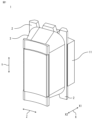
- FIG. 1 is a perspective view showing the configuration of a split coil winding body according to Embodiment 1.
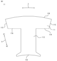
- FIG. FIG. 2 is a plan view showing the structure of a split core piece that constitutes the split coil winding body shown in FIG. 1.
- FIG. FIG. 3 is a plan view showing a configuration in which an insulator is installed on the split core piece shown in FIG. 2.
- FIG. FIG. 3 is a side view showing a configuration in which an insulator is installed on the split core piece shown in FIG. 2.
- FIG. FIG. 2 is a plan view showing a configuration in which a plurality of split coil winding bodies shown in FIG. 1 are arranged in an annular shape.
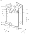
- 1 is a perspective view showing the configuration of a stator according to Embodiment 1.
- FIG. 7 is a perspective view showing the configuration of a rotating electric machine using the stator shown in FIG. 6.
- FIG. FIG. 2 is a schematic cross-sectional view showing the configuration of a mold in Embodiment 1.
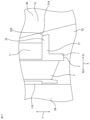
- FIG. 9 is an enlarged schematic view showing the arrangement relationship between the upper side of the split coil winding body shown in FIG. 1 in the axial direction on the paper and the mold die shown in FIG. 8.
- FIG. 9 is an enlarged schematic view showing the arrangement relationship between the upper and lower side of the paper in the axial direction of the split coil winding body shown in FIG. 1 and the mold die shown in FIG. 8.
- FIG. FIG. 9 is a plan view illustrating the force relationship between the split coil wrapping body shown in FIG. 1 placed in the mold shown in FIG. 8 and the mold resin.
- FIG. 7 is a side view showing a configuration in which an insulator is installed on a split core piece in Embodiment 2.
- 9 is an enlarged schematic view showing the arrangement relationship between the upper side of the split coil winding body shown in FIG. 13 in the axial direction on the paper and the mold die shown in FIG. 8.
- FIG. 9 is an enlarged schematic view showing the arrangement relationship between the upper and lower side of the paper in the axial direction of the split coil winding body shown in FIG. 13 and the mold die shown in FIG. 8.
- FIG. FIG. 9 is an enlarged schematic diagram showing the upper side of the paper in the axial direction of the arrangement relationship between another split coil winding body shown in FIG.
- FIG. 7 is a plan view showing the configuration of a stator core in Embodiment 7; 19 is a plan view showing a state of a winding process when an insulator is installed on the core shown in FIG. 18.
- FIG. 7 is a plan view showing the configuration of a stator core in Embodiment 8.
- FIG. 21 is a plan view showing a configuration in which insulators are installed in the iron core shown in FIG. 20 and installed in an annular shape.
- FIG. 21 is a cross-sectional view showing the configuration of a connecting portion of the axially laminated core shown in FIG. 20;
- FIG. 23 is a cross-sectional view showing the structure of a first core material and a second core material of the axially laminated core shown in FIG. 22;
- FIG. 9 is a perspective view showing the configuration of a split core piece in which an insulator according to a ninth embodiment is installed.
- FIG. 25 is a plan view showing a configuration in which a plurality of split core pieces on which insulators shown in FIG. 24 are installed are arranged in a ring shape.
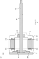
- FIG. 9 is a perspective view showing the configuration of a split core piece in which another insulator is installed according to Embodiment 9; 8 is a sectional view showing the configuration of the rotating electric machine shown in FIG. 7.
- FIG. FIG. 7 is a perspective view showing the configuration of a stator according to Embodiment 3; 12 is a flowchart showing a manufacturing process of a rotating electrical machine according to a third embodiment.
- FIG. 7 is a perspective view showing the configuration of a stator according to Embodiment 4;
- FIG. 7 is a side view showing a configuration in which an insulator is installed on a split core piece in Embodiment 4.
- FIG. 7 is a schematic cross-sectional view showing the configuration of a mold in Embodiment 4.
- FIG. 33 is an enlarged schematic view showing the arrangement relationship between the upper side of the split coil winding body shown in FIG. 31 in the axial direction on the paper and the mold die shown in FIG. 32.
- FIG. 33 is an enlarged schematic view showing the arrangement relationship between the upper side of the split coil winding body shown in FIG. 31 in the axial direction on the paper and the mold die shown in FIG. 32.
- FIG. 33 is an enlarged schematic view showing the arrangement relationship between the upper side of the split coil winding body shown in FIG. 31 in the axial direction on the paper and the mold die shown in FIG. 32.
- FIG. FIG. 7 is an enlarged schematic diagram showing the arrangement relationship between another split core piece and a molding die in Embodiment 4.
- FIG. 9 is a plan view showing a configuration in which an insulator is installed on a split core piece in Embodiment 5.
- FIG. 7 is a plan view showing a configuration in which an insulator is installed on a split core piece in Embodiment 6.
- each direction in the rotating electrical machine is referred to as a circumferential direction Z, an axial direction Y, a radial direction X, an outer side X1 of the radial direction X, and an inner side X2 of the radial direction X. Therefore, the stator and rotor that make up the rotating electrical machine, as well as each part that makes up the stator and rotor, are in the same direction, and will be described using this direction as a reference. Further, the rotating electric machine shown in each figure is one example, and the number of poles and the number of slots of the rotating electric machine can be increased or decreased as appropriate.
- FIG. 1 is a perspective view showing the configuration of a split coil winding body according to a first embodiment.
- FIG. 2 is a plan view showing the structure of a split core piece that constitutes the split coil winding body shown in FIG. 1.
- FIG. 3 is a plan view showing a configuration in which an insulator is installed on the split core pieces shown in FIG. 2.
- FIG. 4 is a side view showing a configuration in which an insulator is installed on the split core pieces shown in FIG. 2.
- FIG. 5 is a plan view showing a configuration in which a plurality of split coil wrapping bodies shown in FIG. 1 are arranged in a ring shape.
- FIG. 6 is a perspective view showing the structure of the stator according to the first embodiment.
- FIG. 6 is a perspective view showing the structure of the stator according to the first embodiment.
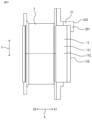
- FIG. 7 is a perspective view showing the configuration of a rotating electrical machine using the stator shown in FIG. 6.
- FIG. 27 is a sectional view showing the configuration of the rotating electric machine shown in FIG. 7. However, unlike FIG. 7, FIG. 27 shows a simplified outline of the molded resin portion 5, which will be described later.
- FIG. 8 is a schematic cross-sectional view showing the configuration of the mold in Embodiment 1.
- FIG. 9 is an enlarged schematic diagram showing the upper side of the paper in the axial direction of the arrangement relationship between the split coil wrapping body shown in FIG. 1 and the mold die shown in FIG. 8.
- FIG. 10 is an enlarged schematic view showing the arrangement relationship between the split coil winding body shown in FIG. 1 and the molding die shown in FIG. 8 from the top and bottom of the paper in the axial direction.
- FIG. 11 is a plan view illustrating the force relationship between the split coil wrapping body shown in FIG. 1 placed in the mold shown in FIG. 8 and the mold resin.
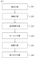
- FIG. 12 is a flowchart showing a method for manufacturing a rotating electric machine according to the first embodiment.
- the split coil winding body 1 constitutes a stator 20 (FIG. 6) of a rotating electrical machine 100 (FIG. 7), which will be described later.
- the split coil winding body 1 includes a split core piece 11, an insulator 2 disposed on the split core piece 11, and a coil 3 formed by winding a conducting wire around the split core piece 11 via the insulator 2. .
- the inner circumferential surface 11A includes teeth portions 112 formed to protrude toward the inner side X2 in the radial direction X.
- the outer side X1 of the core back portion 111 in the radial direction X is defined as an outer circumferential surface 11B
- both ends of the core back portion 111 in the circumferential direction Z are defined as end surfaces 11C
- the inner side X2 of the teeth portion 112 in the radial direction X is defined as a tip surface 11D.
- the split core piece 11 is formed, for example, by laminating a plurality of electromagnetic steel plates in the axial direction Y and fixing them to each other by caulking, welding, or adhesion.
- the insulator 2 includes protrusions 21 and 22 on both end sides in the axial direction Y that extend in the radial direction X toward the outer circumferential surface 11B of the core back portion 111.
- the outer sides X1 of the protrusions 21 and 22 in the radial direction It has protruding surfaces 21A and 22A along.
- the protruding surfaces 21A and 22A are formed with a slope with respect to the axial direction Y.
- the end faces of the projections 21 and 22 on the side opposite to the split core piece 11 in the axial direction Y are defined as shaft end faces 21B and 22B.
- the insulator 2 is made of, for example, an insulating thermoplastic resin, and includes a tip surface 11D on the inner side X2 of the teeth portion 112 in the radial direction X, an end surface 11C on both ends of the core back portion 111 in the circumferential direction Z, and
- the split core piece 11 is covered except for a part of the outer circumferential surface 11B on the outside X1, and the split core piece 11 and the coil 3 are insulated.
- the stator 20 includes a molded resin portion 5 that covers the split coil winding body 1 arranged as shown in FIG. 5 with molded resin as shown in FIG.
- the mold resin portion 5 is formed of a thermosetting resin such as bulk molding compound (BMC).
- the stator 20 is mounted on the molded resin part 5 except for the protruding surfaces 21A and 22A of the protrusions 21 and 22 of the insulator 2 installed on the split coil winding body 1 and the tip surface 11D of the split core piece 11. covered. That is, the protruding surfaces 21A and 22A are exposed from the mold resin part 5 and are not covered with the mold resin part 5. Note that this configuration will be explained in detail in the method for manufacturing the stator 20.
- the rotating electrical machine 100 includes a stator 20, a rotor 40 that is rotatably installed on the inside X2 of the stator 20 in the radial direction X and includes a rotating shaft 41 and a bearing 42. It includes a bracket 7 that holds a bearing 42 that holds a rotating shaft 41 of a rotor 40 installed in an opening 200 (see FIG. 6) at one end of the stator 20 in the axial direction Y.
- a bracket 7 is installed at one end in the axial direction Y, but the invention is not limited to this. , it is also conceivable that the brackets 7 are installed at both ends in the axial direction Y.
- stator 20 of the first embodiment configured as described above and a method of manufacturing the rotating electrical machine 100 using the stator 20 will be described based on FIG. 12.
- an assembly process is performed in which a pre-formed insulator 2 is assembled to the split core piece 11 formed by laminating electromagnetic steel sheets in the axial direction Y, or the insulator 2 is integrally molded (step ST1 in FIG. 12).
- a conducting wire is wound around the teeth 112 of the split core piece 11 via the insulator 2 to form the coil 3, and a winding process is performed to form the split coil winding body 1 shown in FIG. 1 (see FIG. 12).
- Step ST2 the assembly process is performed in which a pre-formed insulator 2 is assembled to the split core piece 11 formed by laminating electromagnetic steel sheets in the axial direction Y, or the insulator 2 is integrally molded.
- a conducting wire is wound around the teeth 112 of the split core piece 11 via the insulator 2 to form the coil 3
- a winding process is performed to form
- an in-mold placement step of arranging the plurality of split coil winding bodies 1 in a ring shape around the central axis of the stator 20 in a mold die 50 (see FIG. 8 described later) (Step ST3 in FIG. 12).
- a molding process is performed to form a mold resin portion 5 using mold resin (step ST4 in FIG. 12), and a stator 20 as shown in FIG. 6 is formed.
- the protruding surfaces 21A and 22A of the insulator 2 are exposed from the molded resin and are not covered with the molded resin.
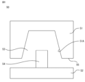
- the molding die 50 includes a movable die 51 and a fixed die 52 that are opened and closed on a particle surface 55, and a cavity 53 is formed between the two.
- a cylindrical center shaft 54 that projects into the cavity 53 is formed in the fixed mold 52 .
- the outer diameter of the center shaft 54 matches the inner diameter of the stator 20.
- the mold inner circumferential surface 51A of the movable mold 51 has a slope with respect to the central axis of the center shaft 54 so that the opening area (opening diameter) increases toward the fixed mold 52.
- FIG. 8 shows the movable mold 51 in the opposite direction of the fixed mold 52 to open the mold, and a plurality of split coils are wound in the cavity 53 around the central axis of the stator 20.
- the bodies 1 are arranged in a ring shape as shown in FIG.
- FIGS. 9 and 10 show the relationship between the split coil wrapping body 1 shown in FIG. 4 and the mold die 50 on the lower side in the axial direction Y on the paper.
- the slope of the protrusion surface 21A of the protrusion 21 on the one end side in the axial direction Y with respect to the axial direction Y, and the axial direction of the protrusion surface 22A of the protrusion 22 on the other end side in the axial direction Y is the same (however, except for the slope angle of 0 degrees).
- the protruding surfaces 21A and 22A are parallel to the mold inner circumferential surface 51A.
- the slope is actually a slope angle of less than 10° with respect to the axial direction Y, and is actually indistinguishable from a plane parallel to the axial direction Y, as shown in FIG. Hateful. Therefore, in FIGS. 9 and 10, the relationship between the slope of the protrusion surfaces 21A and 22A of the protrusions 21 and 22 in the axial direction Y and the slope of the mold inner peripheral surface 51A of the mold die 50 in the axial direction Y is shown. is shown exaggerated.
- the movable mold 51 When the movable mold 51 is continued to be moved and closed, the movable mold 51 is moved because the mold inner peripheral surface 51A of the movable mold 51 and the protruding surfaces 21A and 22A of the protrusions 21 and 22 of the insulator 2 are sloped.
- a mold clamping force which is a load in the axial direction Y during movement, is converted into a load in the radial direction X on the split coil wrapping body 1 .
- the elastic force of the protrusions 21 and 22 pushes the split coil wrapping body 1 from the outside X1 toward the inside X2 in the radial direction X, and the tip surface 11D of the teeth 112 is pressed against the center shaft 54. .
- the interference occurs in the outer X1 direction of the protrusions 21 and 22 in the radial direction X.
- the value obtained by multiplying the load N by the friction coefficient ⁇ N generated between the protruding surfaces 21A, 22A of the protrusions 21, 22 and the mold inner peripheral surface 51A is the value when the protrusions 21, 22 move in the circumferential direction Z due to the resin pressure.
- the state is greater than the load F to be received.
- the protruding surfaces 21A and 22A of the protrusions 21 and 22 press the metal parts when closing the mold so that the split coil wrapping body 1 can be pushed uniformly in the axial direction Y from the outside X1 to the inside X2 in the radial direction X. It is desirable that the protruding surfaces 21A and 22A be formed at the same angle as the slope of the mold inner circumferential surface 51A with respect to the axial direction Y.
- the protruding surfaces 21A and 22A of the protrusions 21 and 22 contact the inner circumferential surface 51A of the mold when the split coil wrapping body 1 is placed in the mold die 50 and the mold is closed.
- the elastic force causes the insulator 2 to push the split core piece 11 from the outside X1 to the inside X2 in the radial direction
- the wrapping body 1 is formed with dimensions that do not allow it to move.
- the protrusions 21 and 22 are not limited to this example, and when the split coil wrapping body 1 is placed in the mold die 50 and the mold is closed, the protrusions 21 and 22 come into contact with the inner circumferential surface 51A of the mold, and are caused by elastic force. Since the tip surface 11D of the teeth portion 112 of the insulator 2 is pressed against the center shaft 54 from the outer side X1 to the inner side X2 in the radial direction The width of the protrusion surfaces 21A, 22A of the protrusions 21, 22 in the circumferential direction Z, and the number of the protrusion surfaces 21A, 22A of the protrusions 21, 22 formed in the circumferential direction Z also differ from one split coil winding body. Instead of one per unit, a plurality of units may be arranged.
- molten mold resin is injected into the cavity 53 to cover the split coil wrapping 1.
- the molding die 50 is heated.
- the mold resin in the cavity 53 is cured, and the stator 20 as shown in FIG. 6 is formed.
- the movable mold 51 is moved in the direction opposite to the fixed mold 52 to open the mold, and the stator 20 is taken out from the mold 50.
- the molded resin part 5 is formed with the protruding surfaces 21A and 22A of the insulator 2 in close contact with the mold inner circumferential surface 51A. 22A is exposed from the mold resin and is not covered with the mold resin.
- the rotating electric machine 100 is manufactured using the stator 20 manufactured as described above.
- a placement step is performed in which the rotor 40 is inserted through the opening 200 of the stator 20 and placed so as to face the tip surface 11D of the teeth portion 112 (step ST5 in FIG. 12).
- an installation step is performed to attach the bracket 7 that holds the bearing 42 that holds the rotating shaft 41 of the rotor 40 to the opening 200 of the stator 20 (step ST6 in FIG. 12), and the manufacturing of the rotating electric machine 100 is completed. .
- An iron core having a core back portion formed in an annular shape and a plurality of teeth portions formed on a radially inner inner circumferential surface of the core back portion at intervals in the circumferential direction and protruding radially inward.
- a stator comprising a coil wound around the teeth portion via an insulator, and a molded resin portion covering the iron core and the coil,
- the core back portion is formed separately at at least one location in the circumferential direction
- the insulator has two or more protrusions in the circumferential direction that protrude radially outward from the outer peripheral surface of the core back portion,
- the molded resin portion does not cover a radially outer protrusion surface along the axial direction of the protrusion,
- the stator described above a rotor coaxially and rotatably disposed inside the stator in the radial direction; and a bracket that holds a bearing that holds the rotating shaft of the rotor, which is installed at at least one end of the stator in the axial direction
- an assembly step of installing the insulator on the iron core a winding step of forming a coil
- the protrusion is configured to form a protrusion surface of the protrusion and the mold resin part in response to a load generated in a radially outward direction of the protrusion with respect to an inner circumferential surface of the mold for forming the mold resin part.
- the protrusion is formed so that the value multiplied by the coefficient of friction generated between the protrusion and the inner circumferential surface of the mold is larger than the load that the protrusion receives in the circumferential direction due to the resin pressure of the mold resin when the mold resin is injected. Because A stator with even better roundness can be obtained.
- the protrusions are formed on both ends of the core back portion in the axial direction, and an axial slope of the protrusion surface on one end of the protrusion in the axial direction; Since the slope of the protrusion surface on the other end side of the protrusion in the axial direction with respect to the axial direction is the same (excluding the slope angle of 0 degrees), A stator with good roundness can be easily obtained.
- stator of the first embodiment configured as described above, Since the protrusions are formed on both ends of the core back portion in the axial direction, A stator with even better roundness can be obtained.
- FIG. 13 is a side view showing a configuration in which an insulator is installed on a split core piece in Embodiment 2.
- FIG. 14 is an enlarged schematic diagram showing the upper side of the paper in the axial direction of the arrangement relationship between the split coil winding body shown in FIG. 13 and the mold die shown in FIG. 8.
- FIG. 15 is an enlarged schematic view showing the arrangement relationship between the split coil winding body shown in FIG. 13 and the molding die shown in FIG. 8 from the top and bottom of the paper in the axial direction.
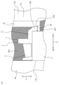
- FIG. 16 is an enlarged schematic view showing the upper side of the paper in the axial direction of the arrangement relationship between another split coil winding body shown in FIG. 13 and the mold die shown in FIG. 8.
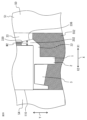
- FIG. 17 is an enlarged schematic view showing the arrangement relationship between the other split coil winding body shown in FIG. 13 and the mold die shown in FIG. 8 from the top and bottom of the paper in the axial direction.
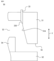
- each slope shown in FIGS. 14 to 16 is actually a slope angle of less than 10° with respect to the axial direction Y, and in reality, it is parallel to the axial direction Y as shown in FIG. It is difficult to distinguish it from the other side. Therefore, in FIGS. 14 to 16, the slopes of the protruding surfaces 21A, 22A of the protruding parts 21, 22 and the extending parts 201, 202 with respect to the axial direction Y, and the axis of the mold inner peripheral surface 51A of the mold die 50 are shown. The relationship between the gradient and the direction Y is illustrated in an exaggerated manner.
- the protrusions 21 and 22 not only protrude outward X1 from the outer circumferential surface 11B of the core back portion 111, but also extend along the outer circumferential surface 11B of the split core piece 11 in the axial direction of the split core piece 11. It has extending portions 201 and 202 that extend toward the Y center side. By providing the extending portions 201 and 202, higher rigidity can be obtained compared to the insulator 2 of the first embodiment.
- the protruding surfaces 21A and 22A of the protruding parts 21 and 22 touch the outer peripheral surface of the core back part 111 when the split coil wrapping body 1 is placed in the mold die 50 and the mold is closed.
- 11B and the inner circumferential surface 51A of the mold come into contact, and the elastic force pushes the split coil wrapping body 1 from the outside X1 to the inside X2 in the radial direction X, and the tip end surface 11D of the teeth portion 112 is pressed against the center shaft 54. .
- This provides a dimensional relationship in which the split coil wrapping body 1 does not move due to resin pressure even when molding resin is injected.
- the slope angle of the protruding surfaces 21A and 22A with respect to the axial direction Y and the slope angle of the mold inner circumferential surface 51A with respect to the axial direction Y are formed to be the same.
- the extending portion 201 is formed apart from the outer circumferential surface 11B of the core back portion 111, and the extending portion 201 is formed in the axial direction Y of the opposing surface 201A facing the core back portion 111 of the extending portion 201.
- the gradient angle ⁇ 22 of the protrusion surface 21A of the protrusion part 21 with respect to the axial direction Y is equal to the axial direction of the mold inner circumferential surface 51A.
- the extending portion 202 is formed apart from the outer circumferential surface 11B of the core back portion 111, and the extending portion 202 is formed in the axial direction Y of the opposing surface 202A facing the core back portion 111.
- the slope angle ⁇ 21 of the projection surface 22A of the protrusion part 22 with respect to the axial direction Y is It is formed at an angle obtained by subtracting a slope angle ⁇ 31 between the opposing surface 202A of the extending portion 202 of the protrusion 22 and the outer circumferential surface 11B of the core back portion 111 from the slope angle ⁇ 11 with respect to the direction Y.
- the slope angle of the part surface 21AA of the protrusion surface 21A of the protrusion 21 with respect to the axial direction Y is set to the inner circumferential surface 51A of the mold.
- the particle surface 55 of the movable mold 51 touches the protrusion 21.
- the shaft end surface is prevented from interfering with the shaft end surface 21B of the projection surface 21A, causing a load in the axial direction Y instead of the radial direction X to be applied to the extension portion 201, and causing shear stress and breakage.
- This can be prevented by reducing the area of 21B, or buckling due to load in the radial direction X being generated in parts other than the extension part 201 of the protrusion 21 after the mold is closed can be prevented.
- the slope angle of the part surface 22AA of the protrusion 22 with respect to the axial direction Y of the mold inner circumferential surface 51A is In addition to making the slope larger than that of the mold inner circumferential surface 51A or making the corner 22AR round, the slope of the partial surface 22AB of the protrusion surface 22A of the protrusion 22 with respect to the axial direction Y is made larger than the slope of the mold inner peripheral surface 51A with respect to the axial direction Y.
- the particle surface 55 of the movable mold 51 touches the protrusion 22.
- the extension part 202 is subjected to a load in the axial direction Y instead of the radial direction X, causing shear stress to occur and breakage. This can be prevented by reducing the area of the extended end surface 22C, or buckling due to load in the radial direction X being generated in parts other than the extending part 202 of the protrusion 22 after the mold is closed can be prevented.
- the opposing surfaces 201A and 202A of the extending portions 201 and 202 of the protrusions 21 and 22 are inclined with respect to the axial direction Y so as to separate from the outer peripheral surface 11B of the core back portion 111. has.
- the split core pieces 11 and the insulator 2 can be fitted even if the split core pieces 11 vary in size.
- the protrusions 21 and 22 contact both the outer circumferential surface 11B of the core back portion 111 and the inner circumferential surface 51A of the mold, and are elastic.
- the force pushes the split coil winding body 1 from the outside X1 to the inside X2 in the radial direction If the body 1 does not move, the width of the protruding surfaces 21A, 22A of the protruding parts 21, 22 in the circumferential direction Z, and the number of protruding surfaces 21A, 22A of the protruding parts 21, 22 formed in the circumferential direction Z, Instead of one piece, a plurality of pieces may be arranged for one split coil wrapping body 1.
- the rotating electrical machine 100 can be configured using the stator 20.
- the protruding portion includes an extending portion extending toward the center in the axial direction along the radially outer peripheral surface of the core back portion of the iron core. A stator with high rigidity and even better roundness can be obtained.
- the extending portion is formed along an outer peripheral surface of the core back portion,
- the direction of the slope of the projection surface of the projection with respect to the axial direction is formed in the same direction as the direction of the slope with respect to the axial direction of the inner peripheral surface of the mold for forming the mold resin part, A stator with even better roundness can be obtained.
- the extending portion is formed away from the outer peripheral surface of the core back portion,
- the slope angle of the protruding surface has an angle obtained by adding the slope angle of the inner circumferential surface of the mold for forming the mold resin portion to the angle formed by the extending portion and the outer circumferential surface of the core back portion.
- the slope angle of the protruding surface has an angle obtained by subtracting the angle between the extension part and the outer peripheral surface of the core back part from the slope angle of the inner peripheral surface of the mold for forming the mold resin part.
- FIG. 28 is a perspective view showing the structure of a stator according to the third embodiment.
- FIG. 29 is a flowchart showing a method for manufacturing a rotating electric machine according to the third embodiment.
- parts similar to those in each of the above embodiments are designated by the same reference numerals, and explanations thereof will be omitted.
- the projections 21 and 22 of the insulator 2 which are not covered with the molded resin part 5 of FIG. 6 described in the first embodiment, are
- the first member 6 covers the protruding surfaces 21A and 22A along the axial direction Y on the outside X1.
- the first member 6 is made of a material different from that of the molded resin part 5, and includes, for example, adhesive, tape, and the like.
- the stator of Embodiment 3 configured as described above and a method of manufacturing a rotating electric machine using the stator will be described based on FIG. 29.
- the assembly process to the molding process steps ST1 to ST4 in FIG. 29
- the protrusion surfaces 21A and 22A along the axial direction Y of the outer side X1 in the radial direction X of the protrusions 21 and 22 of the insulator 2, which are not covered with the molded resin part 5 are covered with the first member 6.
- the process step ST41 in FIG. 29
- the same steps as in the first embodiment described above are performed to complete the manufacturing of the rotating electrical machine 100.
- the same effects as those of the above embodiments are achieved, and Since the protruding surface not covered by the molded resin part is covered with a first member different from the material of the molded resin part, Since the insulator can be prevented from being exposed, water can be prevented from entering from the interface between the insulator and the molded resin part.
- FIG. 30 is an example of a perspective view showing the configuration of a stator according to the fourth embodiment.
- FIG. 31 is a side view showing a configuration in which an insulator is installed on the split core pieces used in the stator shown in FIG. 30.
- FIG. 32 is a schematic cross-sectional view showing the configuration of a mold according to the fourth embodiment.
- 33 to 35 are enlarged schematic diagrams showing the upper side of the paper in the axial direction of the arrangement relationship between the split coil winding body and the mold shown in FIG. 32.
- each slope shown in FIGS. 32 to 36 is actually a slope angle of less than 10° with respect to the axial direction Y, and in reality, it is parallel to the axial direction Y as shown in FIG. It is difficult to distinguish between the two sides. Therefore, in FIGS. 32 to 36, the relationship between the slope of the protruding portion and the extending portion in the axial direction Y, and the slope of the mold inner peripheral surface of the mold die and the movable pin in the axial direction Y is exaggerated. Illustrated.
- the protrusion 21 is formed only on one end side of the split core piece 11 in the axial direction Y (the upper side on the paper of FIG. 31).
- the protruding portion 21 has an extending portion 201 formed to extend toward the center in the axial direction Y along the outer circumferential surface 11B of the outer side X1 in the radial direction X of the core back portion 111 of the split core piece 11. Be prepared.
- the thickness W1 in the radial direction X of the extending portion 201 of the protrusion 21 formed on one end side in the axial direction Y is the thickness W1 of the extending portion 201 on the center side in the axial direction Y (in FIG. It is formed so as to become smaller from the lower end on the plane of the paper toward one end in the axial direction Y (the upper side on the plane of the paper in FIG. 33).
- the molded resin portion 5 covering the split core piece 11 of the stator 20 and the coil 3 has a radially outer surface 333 (see FIG. 31) of the extending portion 201 of the protrusion 21 of the insulator 2. ), and a second mold resin part 552 that covers the other part.
- a boundary line portion (weld line) 555 is formed at the boundary between the first mold resin portion 551 and the second mold resin portion 552.
- a mold die 50 used in the molding process includes a movable pin 33 movable in the axial direction Y in addition to the structure shown in FIG. 8 described in the first embodiment.
- the movable pin 33 has a sloped surface 330 that tapers toward the tip on the side where the split coil wrapping 1 is arranged.
- the slope angle of the slope surface 300 with respect to the axial direction Y is formed to be the same as the slope angle of the surface 333 of the extension portion 201 with respect to the axial direction Y.
- the split coil wrapping body 1 is placed in the mold die 50 and the mold is closed, similarly to the above embodiments.
- the surface 333 of the extending portion 201 of the protrusion 21 and the sloped surface 330 of the movable pin 33 are in close contact with each other.
- the extending portion 201 is sandwiched between the inclined surface 330 of the movable pin 33 and the outer circumferential surface 11B of the core back portion 111 instead of the inner circumferential surface 51A of the mold, and the extending portion 201 Due to the elastic force, the split coil wrapping body 1 is pushed from the outside X1 to the inside X2 in the radial direction X, and the tip surface 11D of the teeth portion 112 is pressed against the center shaft 54. This prevents the split coil winding body 1 from moving due to the resin pressure when molding resin is injected.
- the mold resin flows into the location where the movable pin 33 was present, and the first mold resin portion 551 is formed.
- the state at that time is shown in FIG.
- the first molded resin part 551 is formed so as to cover the surface 333 of the extension part 201, and there is a boundary line at the boundary between the first molded resin part 551 and the second molded resin part 552. 555 is formed.
- the mold resin part 5 consisting of the first mold resin part 551 and the second mold resin part 552 can be created in one step of injecting the mold resin. Only this step can prevent the insulator 2 from being exposed.
- the protrusion 21 is formed only on one end side in the axial direction Y of the core back part 111, but as another example, as shown in FIG. , may be additionally formed on the other end side of the core back portion 111 in the axial direction Y (lower side on the paper surface of FIG. 31).
- the thickness W2 in the radial direction X of the extending portion 202 of the protrusion 22 formed on the other end side in the axial direction Y is the same as the thickness W2 in the radial direction 36) toward the other end in the axial direction Y (lower side on the paper surface of FIG. 36).
- An iron core having a core back portion formed in an annular shape and a plurality of teeth portions formed on a radially inner inner circumferential surface of the core back portion at intervals in the circumferential direction and protruding radially inward.
- a stator comprising a coil wound around the teeth portion via an insulator, and a molded resin portion covering the iron core and the coil
- the core back portion is formed separately at at least one location in the circumferential direction
- the insulator has two or more protrusions in the circumferential direction that protrude radially outward from the outer peripheral surface of the core back portion, The protrusion is formed on one end of the core back portion in the axial direction
- the protruding portion includes an extending portion that is formed to extend toward the center in the axial direction along a radially outer peripheral surface of the core back portion of the iron core,
- the radial thickness of the extending portion of the protruding portion formed at one end in the axial direction is formed such that the thickness in the radial direction becomes smaller toward the one end in the axial direction from the end surface on the center side in the axial direction of the extending portion.
- the radially outer surface of the extension of the protrusion at one end in the axial direction can be used.
- a stator with good roundness can be provided without increasing processing costs, equipment costs, or the number of parts.
- the protrusion is also formed on the other end side of the core back portion in the axial direction,
- the radial thickness of the extending portion of the protrusion formed on the other end in the axial direction increases from the end surface on the center side in the axial direction of the extending portion toward the other end in the axial direction. It was formed in When pressing the iron core and insulator with the molding die when forming the molded resin part, the radially outer surface of the extension of the protrusion on the other end side in the axial direction can be additionally used.
- a stator that reliably has good roundness can be provided without increasing processing costs, equipment costs, or the number of parts.
- the mold resin part is a first mold resin part that covers a radially outer surface of the extending part of the protrusion
- the remaining part is a second mold resin part
- the first molded resin part and the second molded resin part have a boundary line part at the boundary
- Since the first molded resin portion can cover the radially outer surface of the extending portion of the protrusion and prevent exposure of the insulator, it is possible to prevent water from entering from the interface between the insulator and the molded resin portion.
- the second mold resin part is formed with a movable pin in contact with the radially outer surface of the extending part of the protrusion, and then the movable pin is brought into contact with the outer surface of the extending part of the protrusion.
- the first molded resin part is formed in a state separated from the radially outer surface of the extending part, Since the first molded resin portion can cover the radially outer surface of the extending portion of the protrusion and prevent exposure of the insulator, it is possible to prevent water from entering from the interface between the insulator and the molded resin portion.
- FIG. 37 is a plan view showing a configuration in which insulators are installed on split core pieces used in a stator in Embodiment 5.
- parts similar to those in each of the above embodiments are designated by the same reference numerals, and explanations thereof will be omitted.
- a case will be described in which a plurality of protrusions, in this case two protrusions, are provided in the circumferential direction for one split core piece, that is, one tooth portion.
- one split core piece 11 is provided with two protrusions 21 in the circumferential direction Z.
- a dovetail groove 30 is formed between the two protrusions 21 in the circumferential direction Z on the outer circumferential surface 11B of the core back portion 111 of the split core piece 11.
- the dovetail groove 30 is formed to extend from one end of the core back portion 111 of the split core piece 11 in the axial direction Y to the other end.
- the dovetail groove 30 is used to hold the split core pieces 11 during the winding process.
- Each extending portion 201 of the two protrusions 21 includes a line segment that bisects a surface 333 along the axial direction Y on the outside X1 in the radial direction X of each extending portion 201 in the circumferential direction Z, and A surface 334 perpendicular to the surface 333 on the outside X1 in the radial direction X of the extending portion 201 is formed to include the central axis O of the annular core back portion 111 .
- the extending portions 201 of the plurality of protrusions 21 are formed in this way, in the molding process, the plurality of extending portions 201 extend from a plurality of locations in the circumferential direction Z of the core back portion 111 toward the central axis O. This allows the split core pieces 11 to be stably pressed against the center shaft 54 (see FIG. 8) while suppressing the inclination of the split core pieces 11 in the circumferential direction Z. Accuracy can be improved.
- the coil 3 can be stably formed while holding the split core piece 11 using the dovetail groove 30 in the winding process.
- the protrusion has a plurality of protrusions in the circumferential direction with respect to one of the teeth,
- the extending portions of the plurality of protrusions include a line segment that bisects the radially outer surface of the extending portion in the circumferential direction, and Since the vertical plane is formed to include the central axis of the annular core back part, While achieving the same effects as each of the above embodiments, When forming the molded resin part, one tooth part can be held in the molding die at a plurality of extending parts in the circumferential direction, thereby making it possible to improve the accuracy of the inner diameter of the iron core.
- FIG. 38 is a plan view showing a configuration in which insulators are installed on split core pieces used in a stator in Embodiment 6.
- parts similar to those in each of the above embodiments are designated by the same reference numerals, and explanations thereof will be omitted.
- a surface 335 on the outside X1 in the radial direction X of the extending portion 201 protrudes toward the central axis O (see FIG. 37) of the annular core back portion 111. It has a curved surface.
- the tip of the movable pin 33 shown in the fourth embodiment is formed into, for example, a conical shape.
- the radially outer surface of the extending portion along the axial direction has a curved surface that projects toward the central axis of the annular core back portion.
- FIG. 18 is a plan view showing the configuration of the stator core in Embodiment 7.
- FIG. 19 is a plan view showing the state of the winding process when an insulator is installed on the iron core shown in FIG. 18.
- parts similar to those in each of the above embodiments are designated by the same reference numerals, and explanations thereof will be omitted.
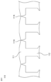
- the core 110 is formed integrally with the core back portion 111 connected in the circumferential direction Z by the thin wall portion 111A, and separated at at least one location in the circumferential direction Z. It is formed.
- the insulator 2 is installed on the iron core 110 formed in this way, and is arranged in a reversely warped shape as shown in FIG. This is because the iron core 110 can be bent at the thin wall portion 111A, so that the teeth portions 112 can be arranged with a wide spacing between them.
- the winding process can be performed in the state shown in FIG. 19, the number of parts can be reduced while achieving high density during winding.
- the thin part 111A is bent so that the iron core 110 has an annular shape with the teeth part 112 facing the inside X2 in the radial direction X. It is placed in the mold 50 in the same manner as in the form of. The following steps are performed in the same manner as in each of the embodiments described above, and the stator 20 and further the rotating electrical machine 100 can be manufactured.
- stator of the seventh embodiment configured as described above, the same effects as those of the above embodiments are achieved, and Since the iron core is formed by connecting the core back portions between the circumferentially adjacent teeth portions at a thin wall portion, High density can be achieved during winding, and furthermore, transportation to the molding process and placement in the molding die can be facilitated.
- FIG. 20 is a plan view showing the configuration of the stator core in Embodiment 8.
- FIG. 21 is a plan view showing a configuration in which insulators are installed in the iron core shown in FIG. 20 in a ring shape.
- FIG. 22 is a cross-sectional view showing the structure of the connecting portion of the axially laminated core shown in FIG. 20.
- FIG. 23 is a sectional view showing the structure of the first core material and the second core material of the axially laminated core shown in FIG. 22.
- parts similar to those in each of the above embodiments are designated by the same reference numerals, and explanations thereof will be omitted.
- FIG. 20 in the core 110, a plurality of split core pieces 11 are connected by rotatable connecting portions 111B at both ends of the core back portion 111 in the circumferential direction Z.
- the insulators 2 are installed on the split core pieces 11 connected in the circumferential direction Z by the connecting portions shown in FIG. 20 and arranged in an annular manner, the structure shown in FIG. 21 is obtained.
- the split core piece 11 is formed of two types of core materials, a first core material 101 and a second core material 102. Then, the first iron core material 101 and the second iron core material 102 are alternately laminated in the axial direction Y. At this time, the position of the core back part 111 of the first iron core material 101 in the circumferential direction Z is shifted from the position of the core back part 111 of the second iron core material 102 in the circumferential direction Z. Thereby, the end portion of the first iron core material 101 in the circumferential direction Z and the end portion of the second iron core material 102 in the circumferential direction Z are laminated so as to overlap in the lamination direction.
- the first iron core material 101 is formed with an uneven portion 101A
- the second iron core material 102 is formed with an uneven portion 102A, and these uneven portions 101A are formed. and the uneven portion 102A are fitted together in the axial direction Y, forming a rotatable connecting portion 111B.
- the core 110 formed in this way in the winding process after placing the insulator 2, the interval between the teeth portions 112 of the split core pieces 11 is widened, as in FIG. 19 in the seventh embodiment. Can be wound.
- the iron core 110 is arranged in an annular shape as in the seventh embodiment, and similarly arranged in the molding die 50. The following steps are performed in the same manner as in each of the embodiments described above, and the stator 20 and further the rotating electrical machine 100 can be manufactured.
- the iron core is formed by dividing the core back portion between the circumferentially adjacent teeth portions in the circumferential direction, and the divided core back portions are connected at a connecting portion rotatable in the circumferential direction. It was formed by Since multiple split core pieces can freely rotate at the connecting part, it is possible to bend them multiple times without reducing mechanical strength, and rotation is easy, improving workability during the winding process. improvement and densification can be achieved.
- FIG. 24 is a perspective view showing the configuration of a split core piece in which an insulator according to Embodiment 9 is installed.
- FIG. 25 is a plan view showing a configuration in which a plurality of split core pieces each having an insulator shown in FIG. 24 are arranged in a ring shape.
- FIG. 26 is a perspective view showing the configuration of a split core piece in which another insulator is installed according to the ninth embodiment.
- the same parts as those in each of the above embodiments are given the same reference numerals, and the description thereof will be omitted.
- an open ring portion 211 is formed in the insulator 2 at one end in the axial direction Y and one end in the circumferential direction Z, which rotatably connects the split core pieces by snap-fit coupling.
- a columnar portion 212 is formed on one end side in the axial direction Y and on the other end side in the circumferential direction Z.
- a columnar portion 222 is formed on the other end side in the axial direction Y and on the one end side in the circumferential direction Z.
- an open ring portion 221 is formed on the other end side in the axial direction Y and on the other end side in the circumferential direction Z.
- the open ring part 211 and the columnar part 212 that are adjacent to each other in the circumferential direction Z of the split core piece 11 on which the insulator 2 is installed are connected to the open ring part 221 and the columnar part 222 by a snap fit connection, As shown in FIG. 25, the split core pieces 11 are arranged in a ring shape.
- adjacent split core pieces 11 are snap-fitted and rotatably connected by the ring-opening portions 211, 221 and columnar portions 212, 222 of the insulator 2.
- winding can be performed with the spacing between the teeth portions 112 of the split core piece 11 being widened, similar to FIG. 19 in the seventh embodiment.
- the iron core 110 is arranged in an annular shape as in the seventh embodiment, and similarly arranged in the molding die 50. The following steps are performed in the same manner as in each of the embodiments described above, and the stator 20 and further the rotating electrical machine 100 can be manufactured.
- FIG. 9 instead of the projections 21 and 22 of the insulator 2 shown above, as shown in FIG. A protrusion 210 is formed for contacting with. Then, a protruding surface 210A extending along the axial direction Y on the outside X1 in the radial direction X of the protruding portion 210 is formed, which is not covered with the molding resin. Note that the other configurations are the same as those of the ninth embodiment shown in FIG. 24, and the stator 20 and rotating electric machine 100 can be manufactured in the same manner, so the description thereof will be omitted as appropriate.
- the iron core and the insulator are formed by being divided in the circumferential direction of the core back portion between the circumferentially adjacent teeth portions,
- the divided insulator has a snap-fit connection in the circumferential direction and a rotatable connection part, so that Since multiple split core pieces can freely rotate at the joint of the insulator, it is possible to bend them multiple times without reducing mechanical strength, and the rotation is easy, making it easier to rotate during the winding process. Improved workability and higher density can be achieved, and furthermore, transportation to the molding process and placement in the molding die can be facilitated.
- the protrusion 21 of the insulator 2 does not need to be formed on the outer side X1 of all the teeth 112 in the radial direction It is also conceivable that they are formed only at two locations T, or only at three locations H surrounded by dotted lines separated by 120 degrees. If formed in this way, the rigidity and roundness will be lower than when formed at locations corresponding to all the teeth portions 112, but the material can be reduced and manufacturing can be done at low cost.
- the protrusions 21 and 22 of the insulator 2 are formed at both ends in the axial direction Y, but the invention is not limited to this, and for example, the protrusions 21 and 22 are formed at either end in the axial direction It is also conceivable that only one end of the insulator 2 is formed, for example, only the protrusion 21 or only the protrusion 22 in FIG. 4 is formed. Although the rigidity and roundness are lower than when they are formed at both ends in the axial direction Y, the material can be reduced and manufacturing can be done at low cost.
- the protrusions 21 and 22 of the insulator 2 are formed at both ends in the axial direction Y, but the invention is not limited to this, and for example, It is also conceivable that the protrusions 21 and the protrusions 22 on the other end are alternately formed in the circumferential direction Z.
- the projections 21 or 22 are formed at one end or the other end in the axial direction Y at locations corresponding to all the teeth 112.
- the rigidity and roundness are lower than when the teeth are formed at both ends in the axial direction Y at locations corresponding to all the teeth portions 112, materials can be reduced and manufacturing can be performed at low cost.
- An iron core having a core back portion formed in an annular shape and a plurality of teeth portions formed on a radially inner inner circumferential surface of the core back portion at intervals in the circumferential direction and protruding radially inward.
- a stator comprising a coil wound around the teeth portion via an insulator, and a molded resin portion covering the iron core and the coil,
- the core back portion is formed separately at at least one location in the circumferential direction
- the insulator has two or more protrusions in the circumferential direction that protrude radially outward from the outer peripheral surface of the core back portion,
- the molded resin portion does not cover a radially outer protrusion surface along an axial direction of the protrusion.
- the protrusion is configured to form a protrusion surface of the protrusion and the mold resin part in response to a load generated in a radially outward direction of the protrusion with respect to an inner circumferential surface of the mold for forming the mold resin part.
- the protrusion is formed so that the value multiplied by the coefficient of friction generated between the protrusion and the inner circumferential surface of the mold is larger than the load that the protrusion receives in the circumferential direction due to the resin pressure of the mold resin when the mold resin is injected.
- the protrusions are formed on both ends of the core back portion in the axial direction, and an axial slope of the protrusion surface on one end of the protrusion in the axial direction;
- the stator according to Supplementary note 1 or 2 wherein the protrusion surface on the other end side of the protrusion in the axial direction has the same slope with respect to the axial direction (excluding a slope angle of 0 degrees).
- the protruding portion is described in Appendix 1 or Appendix 2, wherein the protruding portion includes an extending portion that is formed to extend toward the center in the axial direction along the radially outer peripheral surface of the core back portion of the iron core. Stator of.
- the extending portion is formed away from the outer peripheral surface of the core back portion,
- the slope angle of the protruding surface has an angle obtained by adding the slope angle of the inner circumferential surface of the mold for forming the mold resin portion to the angle formed by the extending portion and the outer circumferential surface of the core back portion.
- the slope angle of the protrusion surface is an angle obtained by subtracting the angle between the extension part and the outer peripheral surface of the core back part from the slope angle of the inner peripheral surface of the mold for forming the mold resin part.
- the iron core and the insulator are formed by being divided in the circumferential direction of the core back portion between the circumferentially adjacent teeth portions,
- a rotating electric machine comprising: a bracket that holds a bearing that holds a rotating shaft of the rotor, which is installed at at least one axial end of the stator.
- Appendix 13 an arrangement step of arranging a rotatable coaxial rotor inside the stator in the radial direction formed by the stator manufacturing method of Appendix 12;
- a method for manufacturing a rotating electric machine which sequentially includes a step of attaching a bracket for holding a bearing for holding a rotating shaft of the rotor to at least one axial end of the stator.
- 1 Split coil winding body 100 Rotating electric machine, 101 First iron core material, 101A Uneven part, 102 Second iron core material, 102A Uneven part, 11 Split core piece, 11A Inner peripheral surface, 11B Outer peripheral surface, 11C End face, 11D Tip Surface, 110 Iron core, 111 Core back part, 111A Thin wall part, 111B Connecting part, 112 Teeth part, 2 Insulator, 20 Stator, 200 Opening part, 201 Extending part, 201A Opposing surface, 202 Extending part, 202A Opposing surface , 21 Projection, 21A Projection surface, 21AA Part surface, 21AR corner, 21B Shaft end surface, 211 Open ring part, 212 Columnar part, 22 Projection, 22A Projection surface, 22AA Part surface, 22AB Part surface, 22AR corner , 22B Shaft end surface, 22C Extended tip surface, 221 Open ring part, 222 Column part, 3 Coil, 30 Dovetail groove, 33 Movable pin, 330 Sloped surface, 333
Landscapes
- Engineering & Computer Science (AREA)
- Power Engineering (AREA)
- Manufacturing & Machinery (AREA)
- Manufacture Of Motors, Generators (AREA)
- Insulation, Fastening Of Motor, Generator Windings (AREA)
- Iron Core Of Rotating Electric Machines (AREA)
Priority Applications (4)
| Application Number | Priority Date | Filing Date | Title |
|---|---|---|---|
| US18/853,363 US20250219491A1 (en) | 2022-06-28 | 2023-06-01 | Stator, rotary electrical machine, method for manufacturing stator, and method for manufacturing rotary electrical machine |
| JP2024530592A JP7738758B2 (ja) | 2022-06-28 | 2023-06-01 | 固定子、回転電機、固定子の製造方法、および、回転電機の製造方法 |
| CN202380048011.4A CN119404421A (zh) | 2022-06-28 | 2023-06-01 | 定子、旋转电机、定子的制造方法及旋转电机的制造方法 |
| JP2025145011A JP2025168451A (ja) | 2022-06-28 | 2025-09-02 | 固定子、回転電機、固定子の製造方法、および、回転電機の製造方法 |
Applications Claiming Priority (2)
| Application Number | Priority Date | Filing Date | Title |
|---|---|---|---|
| JP2022-103206 | 2022-06-28 | ||
| JP2022103206 | 2022-06-28 |
Publications (1)
| Publication Number | Publication Date |
|---|---|
| WO2024004510A1 true WO2024004510A1 (ja) | 2024-01-04 |
Family
ID=89382740
Family Applications (1)
| Application Number | Title | Priority Date | Filing Date |
|---|---|---|---|
| PCT/JP2023/020479 Ceased WO2024004510A1 (ja) | 2022-06-28 | 2023-06-01 | 固定子、回転電機、固定子の製造方法、および、回転電機の製造方法 |
Country Status (4)
| Country | Link |
|---|---|
| US (1) | US20250219491A1 (https=) |
| JP (2) | JP7738758B2 (https=) |
| CN (1) | CN119404421A (https=) |
| WO (1) | WO2024004510A1 (https=) |
Cited By (1)
| Publication number | Priority date | Publication date | Assignee | Title |
|---|---|---|---|---|
| WO2026023017A1 (ja) * | 2024-07-25 | 2026-01-29 | ファナック株式会社 | 固定子コア部分、固定子コア、固定子および電動機 |
Citations (7)
| Publication number | Priority date | Publication date | Assignee | Title |
|---|---|---|---|---|
| JPH08317605A (ja) * | 1995-05-15 | 1996-11-29 | Mitsubishi Electric Corp | モールドモータ |
| JP2010158099A (ja) * | 2008-12-26 | 2010-07-15 | Sanyo Electric Co Ltd | モールドモータ及び電動車両 |
| JP2011030328A (ja) * | 2009-07-23 | 2011-02-10 | Aisan Industry Co Ltd | 回転電動機の固定子及び燃料ポンプ |
| JP2012010550A (ja) * | 2010-06-28 | 2012-01-12 | Minebea Co Ltd | レゾルバのインシュレータ、レゾルバおよびその製造方法 |
| JP2012200114A (ja) * | 2011-03-23 | 2012-10-18 | Panasonic Corp | モールド電動機およびそれを搭載した送風装置。 |
| JP2018082534A (ja) * | 2016-11-15 | 2018-05-24 | 日本電産サンキョー株式会社 | モータの製造方法 |
| WO2022101975A1 (ja) * | 2020-11-10 | 2022-05-19 | 三菱電機株式会社 | 固定子鉄心、固定子、圧縮機、及び圧縮機の製造方法 |
-
2023
- 2023-06-01 US US18/853,363 patent/US20250219491A1/en active Pending
- 2023-06-01 WO PCT/JP2023/020479 patent/WO2024004510A1/ja not_active Ceased
- 2023-06-01 CN CN202380048011.4A patent/CN119404421A/zh active Pending
- 2023-06-01 JP JP2024530592A patent/JP7738758B2/ja active Active
-
2025
- 2025-09-02 JP JP2025145011A patent/JP2025168451A/ja active Pending
Patent Citations (7)
| Publication number | Priority date | Publication date | Assignee | Title |
|---|---|---|---|---|
| JPH08317605A (ja) * | 1995-05-15 | 1996-11-29 | Mitsubishi Electric Corp | モールドモータ |
| JP2010158099A (ja) * | 2008-12-26 | 2010-07-15 | Sanyo Electric Co Ltd | モールドモータ及び電動車両 |
| JP2011030328A (ja) * | 2009-07-23 | 2011-02-10 | Aisan Industry Co Ltd | 回転電動機の固定子及び燃料ポンプ |
| JP2012010550A (ja) * | 2010-06-28 | 2012-01-12 | Minebea Co Ltd | レゾルバのインシュレータ、レゾルバおよびその製造方法 |
| JP2012200114A (ja) * | 2011-03-23 | 2012-10-18 | Panasonic Corp | モールド電動機およびそれを搭載した送風装置。 |
| JP2018082534A (ja) * | 2016-11-15 | 2018-05-24 | 日本電産サンキョー株式会社 | モータの製造方法 |
| WO2022101975A1 (ja) * | 2020-11-10 | 2022-05-19 | 三菱電機株式会社 | 固定子鉄心、固定子、圧縮機、及び圧縮機の製造方法 |
Cited By (1)
| Publication number | Priority date | Publication date | Assignee | Title |
|---|---|---|---|---|
| WO2026023017A1 (ja) * | 2024-07-25 | 2026-01-29 | ファナック株式会社 | 固定子コア部分、固定子コア、固定子および電動機 |
Also Published As
| Publication number | Publication date |
|---|---|
| JP2025168451A (ja) | 2025-11-07 |
| JPWO2024004510A1 (https=) | 2024-01-04 |
| JP7738758B2 (ja) | 2025-09-12 |
| US20250219491A1 (en) | 2025-07-03 |
| CN119404421A (zh) | 2025-02-07 |
Similar Documents
| Publication | Publication Date | Title |
|---|---|---|
| JP6044488B2 (ja) | コイルインシュレータの固定方法および固定構造、ステータ、ならびに、回転電機 | |
| CN103688445B (zh) | 电动机的定子和永磁式旋转电机 | |
| JP5533285B2 (ja) | 絶縁部材、ステータの製造方法 | |
| JP6208331B2 (ja) | アキシャルエアギャップ型回転電機 | |
| US9488506B2 (en) | Resolver | |
| JP5957544B2 (ja) | アキシャルギャップ型回転電機 | |
| CN104106199A (zh) | 旋转电机 | |
| US20040155550A1 (en) | Armature having teeth | |
| JP4502041B2 (ja) | 回転電機の固定子およびその製造方法 | |
| JP4837334B2 (ja) | 永久磁石式回転子 | |
| WO2007119465A1 (ja) | 相間絶縁部材および回転電機 | |
| US20120049685A1 (en) | Axial gap rotating electrical machine | |
| JP2019516336A (ja) | パワーターミナルおよびそれを含むモーター | |
| JP2025168451A (ja) | 固定子、回転電機、固定子の製造方法、および、回転電機の製造方法 | |
| JP6566896B2 (ja) | ステータの製造方法、および巻線装置 | |
| JP2015019505A (ja) | 回転電機ステータ及び回転電機ステータの製造方法 | |
| CN112236925B (zh) | 旋转电机的定子以及旋转电机 | |
| JP2012222944A (ja) | ステータ | |
| JP2008278684A (ja) | 一体成形方法 | |
| JP5050747B2 (ja) | 回転電機の固定子製造方法 | |
| JP2022033401A (ja) | 回転電機のロータ、回転電機、回転電機のロータ製造方法、および回転電機の製造方法 | |
| JP7139933B2 (ja) | 電機子および電機子の製造方法 | |
| JP5665362B2 (ja) | 回転電機 | |
| JP2015033192A (ja) | 回転電機ステータの製造方法及び回転電機ステータ | |
| EP4503408A1 (en) | Stator manufacturing method |
Legal Events
| Date | Code | Title | Description |
|---|---|---|---|
| 121 | Ep: the epo has been informed by wipo that ep was designated in this application |
Ref document number: 23830960 Country of ref document: EP Kind code of ref document: A1 |
|
| ENP | Entry into the national phase |
Ref document number: 2024530592 Country of ref document: JP Kind code of ref document: A |
|
| WWE | Wipo information: entry into national phase |
Ref document number: 18853363 Country of ref document: US |
|
| WWE | Wipo information: entry into national phase |
Ref document number: 202380048011.4 Country of ref document: CN |
|
| NENP | Non-entry into the national phase |
Ref country code: DE |
|
| WWP | Wipo information: published in national office |
Ref document number: 202380048011.4 Country of ref document: CN |
|
| 122 | Ep: pct application non-entry in european phase |
Ref document number: 23830960 Country of ref document: EP Kind code of ref document: A1 |
|
| WWP | Wipo information: published in national office |
Ref document number: 18853363 Country of ref document: US |