WO2023286415A1 - 光ファイバテープ心線 - Google Patents
光ファイバテープ心線 Download PDFInfo
- Publication number
- WO2023286415A1 WO2023286415A1 PCT/JP2022/018749 JP2022018749W WO2023286415A1 WO 2023286415 A1 WO2023286415 A1 WO 2023286415A1 JP 2022018749 W JP2022018749 W JP 2022018749W WO 2023286415 A1 WO2023286415 A1 WO 2023286415A1
- Authority
- WO
- WIPO (PCT)
- Prior art keywords
- density
- density region
- region
- low
- connecting portions
- Prior art date
- Legal status (The legal status is an assumption and is not a legal conclusion. Google has not performed a legal analysis and makes no representation as to the accuracy of the status listed.)
- Ceased
Links
Images



Classifications
-
- G—PHYSICS
- G02—OPTICS
- G02B—OPTICAL ELEMENTS, SYSTEMS OR APPARATUS
- G02B6/00—Light guides; Structural details of arrangements comprising light guides and other optical elements, e.g. couplings
- G02B6/44—Mechanical structures for providing tensile strength and external protection for fibres, e.g. optical transmission cables
- G02B6/4401—Optical cables
- G02B6/4403—Optical cables with ribbon structure
-
- G—PHYSICS
- G02—OPTICS
- G02B—OPTICAL ELEMENTS, SYSTEMS OR APPARATUS
- G02B6/00—Light guides; Structural details of arrangements comprising light guides and other optical elements, e.g. couplings
- G02B6/24—Coupling light guides
- G02B6/255—Splicing of light guides, e.g. by fusion or bonding
-
- G—PHYSICS
- G02—OPTICS
- G02B—OPTICAL ELEMENTS, SYSTEMS OR APPARATUS
- G02B6/00—Light guides; Structural details of arrangements comprising light guides and other optical elements, e.g. couplings
- G02B6/44—Mechanical structures for providing tensile strength and external protection for fibres, e.g. optical transmission cables
- G02B6/4401—Optical cables
- G02B6/4429—Means specially adapted for strengthening or protecting the cables
Definitions
- the present invention relates to optical fiber ribbons. This application claims priority based on Japanese Patent Application No. 2021-115536 filed in Japan on July 13, 2021, the content of which is incorporated herein.
- Patent Document 1 discloses an optical fiber tape cable including a plurality of optical fibers arranged in an arrangement direction perpendicular to the longitudinal direction and a plurality of connecting portions. A plurality of connecting portions are formed between two optical fibers adjacent in the arrangement direction and connect the two optical fibers.
- the optical fiber ribbon of Patent Document 1 has a plurality of high-density regions (connected regions) and a plurality of low-density regions (non-connected regions) alternately arranged in the longitudinal direction. At least two connectors are arranged in each of the plurality of high density regions. In each of the plurality of low-density regions, no connecting portion for fixing the arrangement pitch between two adjacent optical fibers is arranged.
- optical fiber ribbons are sometimes wrapped in a pressure wrap, a sheath, or the like and used as an optical fiber cable. In the manufacture of such an optical fiber cable, a method is adopted in which the optical fiber tape core wire is moved along the longitudinal direction to join the optical fiber tape core wire with other constituent members (press wrap, sheath, etc.). often
- the portion of the optical fiber ribbon where the connecting portion is formed has greater rigidity than the other portions. Therefore, the stiffness of the optical fiber ribbon in each low-density region tends to be lower than the stiffness of the optical fiber ribbon in each high-density region.
- high-density regions with high rigidity and low-density regions with low rigidity are alternately arranged in the longitudinal direction.
- the present invention has been made in consideration of such circumstances, and an object of the present invention is to provide an optical fiber ribbon with improved rigidity.
- an optical fiber ribbon includes five or more optical fibers arranged in an arrangement direction perpendicular to the longitudinal direction, and two optical fibers adjacent in the arrangement direction. and a plurality of connecting portions formed between the optical fibers and connecting the two optical fibers, wherein the plurality of connecting portions are intermittently arranged in the longitudinal direction and the arrangement direction.
- a core wire, wherein the optical fiber tape core wire has at least one first high density region and at least one first low density region located at different positions in the longitudinal direction, and at different positions in the longitudinal direction.
- At least one second high-density region and at least one second low-density region are arranged, and in the first high-density region, among the plurality of connecting portions, in the longitudinal direction and the arrangement direction At least two connecting portions whose positions are different from each other are arranged, and among the plurality of connecting portions, at least two connecting portions whose positions are different from each other in the longitudinal direction and the arrangement direction are arranged in the second high-density region.
- the longitudinal dimension L9 of the portion where the first low-density region and the second low-density region overlap in the arrangement direction, which is lower than the number density of the connecting portions in the second high-density region, is the first low-density region. It is smaller than the longitudinal dimension L6 of the high density region and the longitudinal dimension L8 of the second low density region.
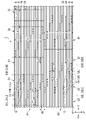
- FIG. 1 is a plan view showing an optical fiber tape core wire according to a first embodiment of the present invention
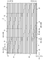
- FIG. FIG. 5 is a plan view showing an optical fiber tape core wire according to a second embodiment of the present invention
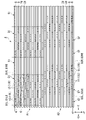
- FIG. 10 is a plan view showing an optical fiber tape core wire according to a third embodiment of the present invention
- FIG. 11 is a plan view showing an optical fiber tape core wire according to a fourth embodiment of the present invention
- FIG. 11 is a plan view showing an optical fiber tape core wire according to a fifth embodiment of the present invention
- FIG. 11 is a plan view showing an optical fiber tape core wire according to a sixth embodiment of the present invention
- the optical fiber ribbon 1 includes a plurality of optical fibers 20. As shown in FIG. A plurality of optical fibers 20 are arranged in a direction perpendicular to the longitudinal direction of each optical fiber 20 .
- the optical fiber ribbon 1 further includes a plurality of connecting portions 10 that connect two adjacent optical fibers 20 among the plurality of optical fibers 20 .
- the optical fiber ribbon 1 has twenty-five optical fibers 20 .
- the number of optical fibers 20 can be changed as appropriate, and the number of optical fibers 20 is not limited as long as it is five or more.
- the longitudinal direction of the optical fiber ribbon is simply referred to as the longitudinal direction X.
- the longitudinal direction X is referred to as the +X orientation or rightward.
- the orientation opposite to the +X orientation is referred to as the -X orientation or leftward.
- the direction in which the plurality of optical fibers 20 are arranged is called an arrangement direction Y.
- the arrangement direction Y is orthogonal to the longitudinal direction X.
- FIG. One orientation in the arrangement direction Y is referred to as the +Y orientation or upward.
- the orientation opposite to the +Y orientation is referred to as the -Y orientation or down.
- a direction orthogonal to the longitudinal direction X and the arrangement direction Y is called a perpendicular direction Z. As shown in FIG.
- Each optical fiber 20 has a waveguide and a coating (not shown).
- the waveguide is made of glass, for example.
- a waveguide has a core and a cladding.
- the covering portion is made of resin or the like and covers the glass portion.
- a specific material for the covering portion is, for example, a UV curable resin.
- Each optical fiber 20 extends along the longitudinal direction X.
- the plurality of optical fibers 20 are arranged in the arrangement direction Y. As shown in FIG. A gap may be provided between two optical fibers 20 adjacent in the arrangement direction Y, or the two optical fibers 20 may be in contact with each other.
- the plurality of optical fibers 20 are arranged in the arrangement direction Y at substantially constant intervals (arrangement pitch P5).
- a gap or a contact surface between two optical fibers 20 adjacent in the arrangement direction Y will be referred to as an inter-fiber region B hereinafter.
- 25 optical fibers 20 and 24 inter-fiber regions B are arranged alternately in the arrangement direction Y.
- FIG. 1 25 optical fibers 20 and 24 inter-fiber regions B are arranged alternately in the arrangement direction Y.
- a plurality of connecting portions 10 are formed in the inter-fiber region B, respectively.
- the plurality of connecting portions 10 are arranged intermittently in the longitudinal direction X and the arrangement direction Y.
- "intermittently arranged" of the plurality of connecting portions 10 includes both cases where the intervals between the connecting portions 10 are constant and cases where they are not constant.
- Each connecting portion 10 connects two optical fibers 20 adjacent to the inter-fiber region B in which the connecting portion 10 is arranged. More specifically, each connecting portion 10 connects the coated portions of two optical fibers 20 adjacent to the inter-fiber region B in which the connecting portion 10 is arranged.
- optical fiber ribbon 1 in the optical fiber ribbon 1 according to this embodiment, two optical fibers 20 adjacent in the arrangement direction Y are intermittently connected to each other in the longitudinal direction X by a plurality of connecting portions 10 .
- the optical fiber tape core wire 1 is also called an intermittently fixed tape core wire 1 .
- Any material capable of connecting the coated portions of the adjacent optical fibers 20 can be used as the connecting portion 10 .
- a UV curable resin may be used as the connecting portion 10 .
- the optical fiber ribbon 1 includes a plurality of first high-density regions D1, a plurality of first low-density regions S1, a plurality of second high-density regions D2, and a plurality of second low-density regions. and S2.
- the plurality of first high-density regions D1 and the plurality of first low-density regions S1 are alternately arranged in the longitudinal direction X.
- the plurality of second high-density regions D2 and the plurality of second low-density regions S2 are alternately arranged in the longitudinal direction X.
- the first high-density area D1 and the second high-density area D2 are arranged at different positions in the arrangement direction Y. As shown in FIG.
- the dimension L1 in the arrangement direction Y of each first high-density region D1 and the dimension L2 in the arrangement direction Y of each first low-density region S1 are substantially equal to each other.
- the dimension L3 in the arrangement direction Y of each second high-density region D2 and the dimension L4 in the arrangement direction Y of each second low-density region S2 are substantially equal to each other.
- the dimension L1 and the dimension L3 may be substantially equal to each other.
- the dimension in the longitudinal direction X of each first high-density region D1 is substantially constant at dimension L5.
- the dimension in the longitudinal direction X of each first low-density region S1 is substantially constant at dimension L6.
- each second high-density region D2 is substantially constant at dimension L7.
- the dimension in the longitudinal direction X of each second low-density region S2 is substantially constant at dimension L8.
- each of the dimensions L5 to L8 may not be substantially constant.
- the dimension L5 and the dimension L7 may be substantially equal to each other.
- Dimension L6 and dimension L8 may be substantially equal to each other.
- each region D1, D2, S1, S2 includes 13 optical fibers 20 and 12 inter-fiber regions B.
- a region obtained by combining the plurality of first high-density regions D1 and the plurality of first low-density regions S1 is called a first region A1.
- a region including the plurality of second high-density regions D2 and the plurality of second low-density regions S2 is referred to as a second region A2.
- the first area A1 and the second area A2 are adjacent to each other in the arrangement direction Y. As shown in FIG. Note that the first area A1 and the second area A2 may not be adjacent to each other in the arrangement direction Y.
- each of the plurality of first high-density regions D1, each of the plurality of first low-density regions S1, each of the plurality of second high-density regions D2, and the plurality of second low-density regions S2 Each is formed in a substantially rectangular shape.
- the right edge of each first high-density area D1 may be referred to as a first right edge D1RE
- the left edge of each first high-density area D1 may be referred to as a first left edge D1LE.
- each edge D1RE, D1LE, D2RE, and D2LE is a line segment parallel to the arrangement direction Y. As shown in FIG. At least one connecting portion 10 is arranged in contact with each of the edges D1RE, D1LE, D2RE, and D2LE.
- the first right edge D1RE of each first high density region D1 is also the left edge of the first low density region S1 adjacent to the right of the first high density region D1.
- the first left edge D1LE of each first high density area D1 is also the right edge of the first low density area S1 adjacent to the left of the first high density area D1. That is, each first high-density area D1 and each first low-density area S1 are partitioned by each first right edge D1RE and each first left edge D1LE.
- the second right edge D2RE of each second high density region D2 is also the left edge of the second low density region S2 adjacent to the right of the second high density region D2.
- each second left edge D2LE of each second high density area D2 is also the right edge of the second low density area S2 adjacent to the left of the second high density area D2. That is, each second high-density region D2 and each second low-density region S2 are partitioned by each second right edge D2RE and each second left edge D2LE.
- each first high-density region D1 and each first low-density region S1 will be described below.
- At least two connecting portions 10 whose positions in the longitudinal direction X and the arrangement direction Y are different from each other among the plurality of connecting portions 10 are arranged in each first high-density region D1.
- 12 connecting portions 10 are arranged in each first high-density region D1.
- the arrangement pattern of the 12 connecting portions 10 included in each first high-density region D1 is substantially the same among the first high-density regions D1.
- three connecting portion groups G are arranged in each first high-density region D1, and the three connecting portion groups G are arranged in the arrangement direction Y. As shown in FIG. In each connecting portion group G, four connecting portions 10 are arranged in a straight line.
- 12 connecting portions 10 are periodically arranged in the arrangement direction Y with four connecting portions 10 (connecting portion group G) as one unit in each first high-density region D1.
- the number of connecting portions 10 included in each connecting portion group G can be changed as appropriate, and the number of connecting portions 10 is not limited as long as the number is two or more.
- a plurality of connecting portions may be arranged in a curved line.
- the number of connecting portion groups G included in each first high-density region D1 can be changed as appropriate.
- the number of connecting portions 10 included in each first high-density region D1 can be changed as appropriate, and the number of connecting portions 10 is not limited as long as the number is two or more.
- each connecting portion group G the four connecting portions 10 are arranged in the longitudinal direction X at a substantially constant pitch P1.
- the four connecting portions 10 are arranged at substantially constant intervals P2 in the longitudinal direction X.
- the four connecting portions 10 may be arranged in the longitudinal direction X without leaving an interval P2. That is, each connection part 10 may mutually overlap in the arrangement direction Y.
- the inter-fiber region B in which a certain connecting portion 10 is arranged and the inter-fiber region B in which the connecting portion 10 closest to the connecting portion 10 is arranged are arranged in the arrangement direction They are adjacent in Y.
- each connecting portion group G the connecting portion 10 positioned highest among the four connecting portions 10 included in the connecting portion group G is referred to as an upper end connecting portion.
- the connecting portion 10 located at the lowest position among the four connecting portions 10 included in the connecting portion group G is referred to as a lower end connecting portion.
- the three connecting portion groups G are adjacent in the arrangement direction Y. As shown in FIG. For example, the inter-fiber region B in which the upper end connecting portion in the connecting portion group G located in the center of the three connecting portion groups G is arranged, and the connecting portion group G located in the upper side among the three connecting portion groups G It is adjacent to the inter-fiber region B where the lower end connecting portion is arranged.
- each connecting portion group G is adjacent to each other in the arrangement direction Y, one connecting portion 10 is arranged in each inter-fiber region B included in each first high-density region D1.
- each connection part group G does not need to be adjacent in the arrangement direction Y.
- the rightmost three connecting portions 10 of the four connecting portions 10 included in each connecting portion group G of each first high-density region D1 are mutually arranged in the longitudinal direction X. located at approximately the same position. These three connecting portions 10 are in contact with the first right edge D1RE.
- the leftmost three connecting portions 10 among the four connecting portions 10 included in each connecting portion group G are arranged at approximately the same positions in the longitudinal direction X. As shown in FIG. These three connecting portions 10 are in contact with the first left edge D1LE.
- each of the second high-density regions D2 also has a connecting portion group G similar to that of the first high-density region D1 (details will be described later).
- the connecting portion group G is included in one of the plurality of first high-density regions D1 and the plurality of second high-density regions D2.
- the first high-density region D1 and the second high-density region D2 may include connecting portions 10 that do not belong to the connecting portion group G.
- the number density of the connecting portions 10 in each first low-density region S1 is lower than the number density of the connecting portions 10 in each first high-density region D1.
- the number density of the connecting portions 10 in each second low-density region S2 is lower than the number density of the connecting portions 10 in each second high-density region D2.
- the “number density of the connecting portions 10 in the first low-density region S1” is a value obtained by dividing the number of connecting portions 10 included in the first low-density region S1 by the area of the first low-density region S1.
- the “number density of the connecting portions 10 in the first high-density region D1” is a value obtained by dividing the number of connecting portions 10 included in the first high-density region D1 by the area of the first high-density region D1.
- the number densities of the second low-density area S2 and the second high-density area D2 are similarly defined.
- each low-density region S1, S2 does not include the connecting portion 10.
- the number density of the connecting portions 10 in the low density regions S1 and S2 is zero.
- the connecting portion 10 may be included in the low density areas S1 and S2.
- each second high-density region D2 and each second low-density region S2 will be described below.
- the configuration of each second high-density area D2 is substantially the same as the configuration of each first high-density area D1.
- the configuration of each second low density region S2 is substantially the same as the configuration of each first low density region S1.
- At least two connecting portions 10 whose positions in the longitudinal direction X and the arrangement direction Y are different from each other among the plurality of connecting portions 10 are arranged in each second high-density region D2.
- 12 connecting portions 10 are arranged in each second high-density region D2.
- the arrangement pattern of the 12 connecting portions 10 included in each second high-density region D2 is substantially the same among the second high-density regions D2.
- three connection portion groups G are arranged in each second high-density region D2, and the three connection portion groups G are arranged in the arrangement direction Y.
- four connecting portions 10 are arranged in a straight line.
- 12 connecting portions 10 are periodically arranged in the arrangement direction Y with four connecting portions 10 (connecting portion group G) as one unit in each second high-density region D2.
- the number of connecting portions 10 included in each connecting portion group G can be changed as appropriate, and the number of connecting portions 10 is not limited as long as the number is two or more.
- a plurality of connecting portions may be arranged in a curved line.
- the number of connecting portion groups G included in each second high-density region D2 can be changed as appropriate.
- the number of connecting portions 10 included in each second high-density region D2 can be changed as appropriate, and the number of connecting portions 10 is not limited as long as the number is two or more.
- each connecting portion group G the four connecting portions 10 are arranged in the longitudinal direction X at a substantially constant pitch P3.
- the four connecting portions 10 are arranged at substantially constant intervals P4 in the longitudinal direction X.
- the four connecting portions 10 may be arranged in the longitudinal direction X without leaving an interval P4. That is, each connection part 10 may mutually overlap in the arrangement direction Y.
- the inter-fiber region B in which a certain connecting portion 10 is arranged and the inter-fiber region B in which the connecting portion 10 adjacent to the connecting portion 10 is arranged are arranged in the arrangement direction Y adjacent in The three connecting portion groups G are adjacent in the arrangement direction Y. As shown in FIG.
- each connecting portion group G is adjacent to each other in the arrangement direction Y, one connecting portion 10 is arranged in each inter-fiber region B included in each second high-density region D2. In addition, each connection part group G does not need to be adjacent in the arrangement direction Y.
- the rightmost three connecting portions 10 of the four connecting portions 10 included in each connecting portion group G of each second high-density region D2 are mutually arranged in the longitudinal direction X. located at approximately the same position. These three connecting portions 10 are in contact with the second right edge D2RE. Similarly, the leftmost three connecting portions 10 among the four connecting portions 10 included in each connecting portion group G are arranged at approximately the same positions in the longitudinal direction X. As shown in FIG. These three connecting portions 10 are in contact with the second left edge D2LE.
- each first high-density region D1, each first low-density region S1, each second high-density region D2, and each second low-density region S2 will be described below.
- At least one second low-density region S2 overlapping in the arrangement direction Y exists in each first low-density region S1 according to the present embodiment.
- each first low-density region S1 and each second low-density region S2 overlap each other in the arrangement direction Y.
- the dimension in the longitudinal direction X of each overlapping portion is substantially constant at dimension L9.
- the dimension L9 is smaller than the dimension L6 in the longitudinal direction X of each first low density region S1 and the dimension L8 in the longitudinal direction X of each second low density region S2. That is, L9 ⁇ L6 and L9 ⁇ L8 are satisfied. Also, the dimension L9 is smaller than the dimension L5 in the longitudinal direction X of each first high density region D1 and the dimension L7 in the longitudinal direction X of each second high density region D2. That is, L9 ⁇ L5 and L9 ⁇ L7 are satisfied.
- the dimension in the longitudinal direction X of the portion having the lowest rigidity in the longitudinal direction X of the optical fiber ribbon 1 (that is, the portion where the first low-density region S1 and the second low-density region S2 overlap in the arrangement direction Y) L9 is shorter than L5-L8.
- the area of the portion having the lowest rigidity in the longitudinal direction X of the optical fiber ribbon 1 (that is, the portion having the dimension L9) can be reduced, and the rigidity of the optical fiber ribbon 1 can be increased as a whole.
- each inter-fiber region B included in each first high-density region D1 the rightmost connecting portion 10 will be referred to as a first right end connecting portion 11R.
- the leftmost connecting portion 10 is referred to as a first left end connecting portion 11L.
- the rightmost connecting portion 10 is referred to as a second right end connecting portion 12R.
- the leftmost connecting portion 10 is referred to as a second left end connecting portion 12L.
- the connecting portions 10 arranged in the inter-fiber regions B are Only one. Therefore, all the connecting portions 10 included in each first high-density region D1 correspond to both the first right end connecting portion 11R and the first left end connecting portion 11L. Similarly, in the example of FIG. 1, all the connecting portions 10 included in each second high-density region D2 correspond to both the second right end connecting portion 12R and the second left end connecting portion 12L.
- a straight line connecting the right ends of the two rightmost first right end connecting portions 11R in each first high-density region D1 is referred to as a first right straight line D1R.
- a first right straight line D1R is defined. The same applies to the first left straight line D1L, the second right straight line D2R, and the second left straight line D2L defined below.
- each first high-density area D1 a straight line connecting the left ends of the leftmost two first left end connecting portions 11L is referred to as a first left straight line D1L.
- a straight line connecting the right ends of the two rightmost second right end connecting portions 12R is referred to as a second right straight line D2R.
- a straight line connecting the left ends of the two leftmost second left end connecting portions 12L is referred to as a second left straight line D2L.
- each first right straight line D1R overlaps each first right edge D1RE
- each first left straight line D1L overlaps each first left edge D1LE.
- each second right straight line D2R overlaps each second right edge D2RE.
- all the connecting portions 10 overlapping the first right straight line D1R among the plurality of connecting portions 10 included in each first high-density region D1 do not overlap each of the plurality of second right straight lines D2R.
- all of the connecting portions 10 overlapping the first left straight line D1L does not overlap each of the plurality of second left straight lines D2L.
- All of the connecting portions 10 overlapping the second right straight line D2R among the plurality of connecting portions 10 included in each second high-density region D2 does not overlap with each of the plurality of first right straight lines D1R.
- All of the connecting portions 10 overlapping the second left straight line D2L among the plurality of connecting portions 10 included in each second high-density region D2 does not overlap with each of the plurality of first left straight lines D1L.
- the optical fiber ribbon 1 includes a plurality of first high-density regions D1 and a plurality of second high-density regions D2 in which many connecting portions 10 are arranged, and few connecting portions 10 arranged (especially It has a plurality of first low-density regions S1 and a plurality of second low-density regions S2 (wherein the connecting portion 10 is not arranged in the example of FIG. 1).
- the plurality of optical fibers 20 are connected to each other and integrated.
- the connecting portion 10 also serves to fix the arrangement pitch P5 between the two adjacent optical fibers 20 . Therefore, the arrangement pitch P5 can be stabilized in each of the first high-density regions D1 and each of the second high-density regions D2.
- a fusion splicer is generally used.
- a plurality of grooves extending along the longitudinal direction X are formed in the fuser.
- each optical fiber 20 included in the optical fiber ribbon is inserted one by one through the plurality of grooves described above for alignment.
- the arrangement pitch P5 is fixed by the connecting portion 10 .
- the optical fiber ribbon 1 has a plurality of first low-density regions S1 and a plurality of second low-density regions S2.
- first low-density areas S1 and each of the second low-density areas S2 few or no connecting portions 10 for fixing the arrangement pitch P5 between two adjacent optical fibers 20 are arranged. Therefore, the user can change the arrangement pitch P5 by pulling or compressing the optical fiber ribbon 1 in the arrangement direction Y in the first low-density area S1 or the second low-density area S2.
- This makes it possible to use a fusion splicer having an arrangement pitch P5 different from that of the optical fiber tape core wires 1 when fusion splicing the optical fiber ribbon core wires 1 .
- the optical fiber tape core wires 1 can be fusion-spliced to the optical fiber tape core wires having an arrangement pitch P5 different from that of the optical fiber tape core wires 1 concerned.
- the optical fiber tape core wire 1 may be used as an optical fiber cable, for example, wrapped in a pressure wrap, a sheath, or the like.
- the optical fiber tape core wire 1 is moved along the longitudinal direction X, and the optical fiber tape core wire 1 and other constituent members (press winding, sheath, etc.) are joined together. are often adopted.
- the portion where the connecting portion 10 is formed between the optical fibers 20 has greater rigidity than the portion without the connecting portion 10 . Therefore, the rigidity of the optical fiber ribbon 1 in each of the low density regions S1 and S2 tends to be lower than the rigidity of the optical fiber ribbon 1 in each of the high density regions D1 and D2.
- optical fiber tape core wire having a chisel there are portions (each low-density region) with extremely low stiffness in the longitudinal direction of the optical fiber tape core wire.
- the optical fiber tape core wire having such an extremely low-rigidity portion when the optical fiber tape core wire is moved, the optical fiber tape core wire is wavy or twisted at the extremely low-rigidity portion. It was possible. Such undulations and undulations of the optical fiber tape cord impede the smooth production of optical fiber cables.
- the optical fiber ribbon 1 has both the first area A1 and the second area A2, and the first area A1 and the second area A2 are displaced from each other in the longitudinal direction X. ing. More specifically, each of the first high-density regions D1 and each of the second high-density regions D2 are arranged to be offset from each other in the longitudinal direction X, and each of the first low-density regions S1 and each of the second low-density regions S2 are arranged offset from each other in the longitudinal direction X.
- a portion having the lowest rigidity in the longitudinal direction X of the optical fiber tape core wire 1 (that is, a portion where the first low-density region S1 and the second low-density region S2 overlap in the arrangement direction Y)
- Dimension L9 is shortened. That is, the dimension L9 in the longitudinal direction X of the portion of the optical fiber ribbon 1 having particularly low rigidity can be shortened. Therefore, the rigidity of the optical fiber tape core wire 1 can be increased as a whole, and waviness and twisting of the optical fiber tape core wire 1 can be suppressed when the optical fiber tape core wire 1 is moved.
- the optical fiber ribbon 1 is provided between five or more optical fibers 20 arranged in the arrangement direction Y and two optical fibers 20 adjacent in the arrangement direction Y.
- the optical fiber tape core wire 1 is provided with a plurality of connecting portions 10 formed to connect the two optical fibers 20, and the plurality of connecting portions 10 are intermittently arranged in the longitudinal direction X and the arrangement direction Y.
- the optical fiber tape core wire 1 includes a plurality of first high-density regions D1 and a plurality of first low-density regions S1 alternately arranged in the longitudinal direction X, and a plurality of A second high-density region D2 and a plurality of second low-density regions S2 are provided, and each of the plurality of first high-density regions D1 has a position in the longitudinal direction X and the arrangement direction Y among the plurality of connecting portions 10 are arranged, and in each of the plurality of second high-density regions D2, at least two of the plurality of connecting portions 10 whose positions in the longitudinal direction X and the arrangement direction Y are different from each other are arranged.
- the connecting portions 10 are arranged, and the number density of the connecting portions 10 in each of the plurality of first low-density regions S1 is lower than the number density of the connecting portions 10 in each of the plurality of first high-density regions D1.
- the number density of the connecting portions 10 in each of the two low-density regions S2 is lower than the number density of the connecting portions 10 in each of the plurality of second high-density regions D2, and each of the plurality of first low-density regions S1 and the plurality of
- the dimension L9 in the longitudinal direction X of each portion overlapping with each of the second low-density regions S2 in the arrangement direction Y is equal to the dimension L6 in the longitudinal direction X of each of the plurality of first low-density regions S1 and the second low-density region S2. is smaller than the dimension L8 in the longitudinal direction X of each.
- the first low-density region S1 having a lower rigidity than the first high-density region D1 and the second low-density region S2 having a lower rigidity than the second high-density region D2 are displaced in the longitudinal direction X. are placed.
- the portion having the lowest rigidity in the longitudinal direction X of the optical fiber ribbon 1 that is, , the portion where the first low-density region S1 and the second low-density region S2 overlap in the arrangement direction Y
- the dimension L9 in the longitudinal direction X becomes shorter. Therefore, the rigidity of the optical fiber tape core wire 1 can be increased as a whole, and waviness and twisting of the optical fiber tape core wire 1 can be suppressed when the optical fiber tape core wire 1 is moved.
- the connecting portion 10 that overlaps with the first right straight line D1R does not overlap with each of the plurality of second right straight lines D2R.
- the connecting portions 10 that overlap the first left straight line D1L do not overlap the plurality of second left straight lines D2L, and the plurality of second high-density regions Of the plurality of connecting portions 10 included in each of the regions D2
- the connecting portions 10 overlapping the second right straight lines D2R do not overlap with each of the plurality of first right straight lines D1R
- each of the plurality of second high-density regions D2 Among the plurality of connecting portions 10 included in , the connecting portion 10 overlapping the second left straight line D2L does not overlap each of the plurality of first left straight lines D1L.
- the displacement in the longitudinal direction X between the first low-density region S1 and the second low-density region S2 becomes greater.
- the dimension L9 becomes shorter.
- the dimension L9 in the longitudinal direction X of each portion where each of the plurality of first low-density regions S1 and each of the second low-density regions S2 overlaps in the arrangement direction Y is the length of each of the plurality of first high-density regions D1. It is smaller than the dimension L5 in the longitudinal direction X and the dimension L7 in the longitudinal direction X of each of the plurality of second high-density regions D2.
- the dimension in the longitudinal direction X of the high-density regions D1 and D2 having high rigidity is larger than that of the portion having particularly low rigidity in the longitudinal direction X of the optical fiber ribbon 1 . Therefore, the rigidity of the optical fiber ribbon 1 as a whole is further improved.
- At least one connecting portion 10 is arranged in each of the plurality of inter-fiber regions B included in each of the plurality of first high-density regions D1, and each of the plurality of second high-density regions D2 At least one connecting portion 10 is arranged in each of the plurality of inter-fiber regions B included.
- At least one connecting portion 10 is arranged on each of the plurality of first right edges D1RE and each of the plurality of first left edges D1LE, and each of the plurality of second right edges D2RE and At least one connecting portion 10 is arranged on each of the plurality of second left edges D2LE.
- the rigidity of each first high-density region D1 can be improved compared to, for example, the case where the connecting portion 10 is not arranged at each first right edge D1RE and each first left edge D1LE.
- the rigidity of each second high-density region D2 can be improved compared to the case where the connecting portion 10 is not arranged on each of the second right edge D2RE and each of the second left edge D2LE. Therefore, the rigidity of the optical fiber tape cable core 1 can be improved as a whole.
- a first region A1 which is a region including a plurality of first high-density regions D1 and a plurality of first low-density regions S1, and a plurality of second high-density regions D2 and a plurality of second low-density regions S2 are combined.
- the arrangement direction Y it is adjacent to the second area A2, which is the area where the second area A2 is located.
- the dimension L1 of each of the plurality of first high-density regions D1 and the dimension L2 of each of the plurality of first low-density regions S1 are equal to each other, and the dimension of each of the plurality of second high-density regions D2
- Each dimension L3 and each dimension L4 of the plurality of second low-density regions S2 are equal to each other.
- the first high-density regions D1 and the second high-density regions D2 do not overlap each other in the arrangement direction Y.
- each first low-density region S1 and the two second low-density regions S2 closest to the first low-density region S1 are arranged such that their ends in the longitudinal direction X overlap in the arrangement direction Y.
- each second low-density region S2 and the two first low-density regions S1 closest to the second low-density region S2 are arranged so that their ends in the longitudinal direction X overlap in the arrangement direction Y. are distributed.
- the entirety of the first high-density region D1 in the longitudinal direction X is adjacent to the second low-density region S2 in the arrangement direction Y.
- the entirety of the second high-density region D2 in the longitudinal direction X is adjacent to the first low-density region S1 in the arrangement direction Y.
- the first low-density area S1 which is a portion having lower rigidity than the first high-density area D1
- the second low-density region S2 which is less rigid than the second high-density region D2 is reinforced by the first high-density region D1.
- each of the plurality of first high-density regions D1 and each of the plurality of second high-density regions D2 do not overlap each other in the arrangement direction Y.
- the low-rigidity low-density regions S1, S2 can be reinforced by the high-rigidity high-density regions D1, D2. Therefore, the rigidity of the optical fiber tape cable core 2 can be improved as a whole.
- the optical fiber ribbon 3 according to the present embodiment shown in FIG. 3 differs from that of the first embodiment in the positional relationship between the regions D1, D2, S1, and S2.
- each first low density region S1 and each second low density region S2 do not overlap each other.
- each first high-density region D1 and the two second high-density regions D2 closest to the first high-density region D1 are arranged such that their ends in the longitudinal direction X overlap in the arrangement direction Y.
- each second high-density region D2 and the two first high-density regions D1 closest to the second high-density region D2 are arranged such that their ends in the longitudinal direction X overlap in the arrangement direction Y. are distributed.
- the first high-density region D1 or the second high-density region D2 is arranged at any position in the longitudinal direction X of the optical fiber ribbon 3. Therefore, a region with high rigidity is arranged at any position in the longitudinal direction X of the optical fiber ribbon 3 .
- each of the plurality of first low density regions S1 and each of the plurality of second low density regions S2 do not overlap each other. With this configuration, the rigidity of the optical fiber tape cable core 3 can be improved more reliably.
- a plurality of inter-fiber regions B (12 locations in FIG. 4) included in the high-density regions D1 and D2 are provided with connecting portions 10, respectively. are arranged (two in FIG. 4).
- 24 connecting portions 10 are arranged in each of the high density regions D1 and D2.
- three or more connecting portions 10 may be arranged in each inter-fiber region B.
- FIG. A different number of connecting portions 10 may be arranged in each inter-fiber region B.
- each inter-fiber region B in the high-density regions D1 and D2 includes a plurality of connecting portions 10, in each inter-fiber region B, the connecting portion 10 corresponding to the first right end connecting portion 11R and the second 1 and the connecting portion 10 corresponding to the left end connecting portion 11L are different from each other.
- the same effect as the optical fiber ribbon 1 according to the first embodiment can be obtained. Also, by increasing the number of connecting portions 10 arranged in each inter-fiber region B, the rigidity of the optical fiber tape core wires 4 in each of the high-density regions D1 and D2 can be improved. Thereby, the rigidity of the optical fiber ribbon 4 as a whole can be further improved.
- one connecting portion group G is arranged in each of the high density regions D1 and D2.
- a plurality of (12 in FIG. 5) connecting portions 10 are arranged in a row.
- 12 connecting portions are connected in a curved line.
- the pitches P1 and P3 at which the connecting portions 10 are arranged in the connecting portion group G included in the high-density regions D1 and D2 are not constant.
- each first high-density region D1 the first right edge D1RE and the first right straight line D1R do not overlap, and the first left edge D1LE and the first left straight line D1L do not overlap.
- the second right edge D2RE and the second right straight line D2R do not overlap, and the second left edge D2LE and the second left straight line D2L do not overlap.
- the connecting portions 10 overlapping the first right straight line D1R It does not overlap each of the straight lines D2R.
- the connecting portion 10 overlapping the first left straight line D1L does not overlap each of the plurality of second left straight lines D2L.
- the connecting portion 10 overlapping the second right straight line D2R does not overlap each of the plurality of first right straight lines D1R.
- the connecting portions 10 overlapping the second left straight line D2L do not overlap each of the plurality of first left straight lines D1L.
- the same effect as the optical fiber ribbon 1 according to the first embodiment can be obtained. Further, since the plurality of connecting portions 10 included in each of the high-density regions D1 and D2 are connected as one connecting portion group G, the plurality of connecting portions 10 can be traversed in each of the high-density regions D1 and D2. figure, figure written in one stroke). As a result, for example, when the optical fiber ribbon 5 is manufactured, when the dispenser that discharges the resin to be the connecting portion 10 is moved, the movement distance of the dispenser is shortened, and the manufacturing efficiency is improved.
- connecting portions 10 are arranged in the low density regions S1 and S2. Also in the optical fiber ribbon 6 according to the present embodiment, the number density of the connecting portions 10 in each first low density region S1 is lower than the number density of the connecting portions 10 in each first high density region D1. Similarly, the number density of the connecting portions 10 in each second low-density region S2 is lower than the number density of the connecting portions 10 in each second high-density region D2.
- the same effect as the optical fiber ribbon 1 according to the first embodiment can be obtained.
- the connecting portions 10 are also arranged in the low density areas S1 and S2, the rigidity of the optical fiber ribbon 6 in the low density areas S1 and S2 can be improved. Thereby, the rigidity of the optical fiber tape cable core 6 can be improved as a whole.
- the pitch between the optical fibers 20 can be changed by peeling off the connecting portions 10 included in the low-density regions S1 and S2. Since the number of connecting portions 10 included in the low-density regions S1 and S2 is small, it is easy to separate them.
- L9 ⁇ L8 was satisfied.
- L9 ⁇ L6 and L9 ⁇ L8 for at least one first high-density region D1, first low-density region S1, second high-density region D2, and second low-density region S2 The effect of improving rigidity is obtained. The same applies to other dimensional relationships.
- the arrangement pattern of the plurality of connecting portions 10 included in each first high-density region D1 may not be the same among the first high-density regions D1.
- the arrangement pattern of the plurality of connecting portions 10 included in each second high-density region D2 may not be the same among the second high-density regions D2.
- each connecting portion 10 in the longitudinal direction X and the arrangement direction Y may not be the same among the connecting portions 10 .
- the plurality of connecting portions 10 included in each of the high-density regions D1 and D2 may not form the connecting portion group G.
- the plurality of connecting portions 10 may be randomly arranged in each of the high-density regions D1 and D2.
- a plurality of connecting portions 10 may be randomly arranged in each of the low-density regions S1 and S2.
- Optical fiber ribbon 10 ... Connecting part 11R... First right end connecting part 11L... First left end connecting part 12R... Second right end connecting part 12L... Second left end connecting part 20... Optical fiber D1... First height Density area D1R... First right straight line D1RE... First right edge (edge in longitudinal direction of first high density area) D1L... First left straight line D1LE... First left edge (longitudinal direction of first high density area) edge) D2... Second high-density area D2R... Second right straight line D2RE... Second right edge (edge in the longitudinal direction of the second high-density area) D2L... Second left straight line D2LE...
- Second left edge End edge in the longitudinal direction of the second high-density area
- S1 First low-density area
- S2 Second low-density area
- A1 First area
- A2 Second area
- X Longitudinal direction
- Y Arrangement direction
Landscapes
- Physics & Mathematics (AREA)
- General Physics & Mathematics (AREA)
- Optics & Photonics (AREA)
- Engineering & Computer Science (AREA)
- Plasma & Fusion (AREA)
- Mechanical Coupling Of Light Guides (AREA)
- Optical Fibers, Optical Fiber Cores, And Optical Fiber Bundles (AREA)
- Light Guides In General And Applications Therefor (AREA)
Priority Applications (7)
| Application Number | Priority Date | Filing Date | Title |
|---|---|---|---|
| AU2022310612A AU2022310612B2 (en) | 2021-07-13 | 2022-04-25 | Optical fiber ribbon |
| CA3224169A CA3224169C (en) | 2021-07-13 | 2022-04-25 | Optical fiber ribbon |
| CN202280045857.8A CN117581139A (zh) | 2021-07-13 | 2022-04-25 | 光纤带芯线 |
| KR1020247000961A KR20240017957A (ko) | 2021-07-13 | 2022-04-25 | 광섬유 테이프 심선 |
| US18/578,638 US20240319463A1 (en) | 2021-07-13 | 2022-04-25 | Optical fiber ribbon |
| JP2023535143A JP7634680B2 (ja) | 2021-07-13 | 2022-04-25 | 光ファイバテープ心線 |
| EP22841762.2A EP4372441A4 (en) | 2021-07-13 | 2022-04-25 | Optical fiber ribbon |
Applications Claiming Priority (2)
| Application Number | Priority Date | Filing Date | Title |
|---|---|---|---|
| JP2021115536 | 2021-07-13 | ||
| JP2021-115536 | 2021-07-13 |
Publications (1)
| Publication Number | Publication Date |
|---|---|
| WO2023286415A1 true WO2023286415A1 (ja) | 2023-01-19 |
Family
ID=84919273
Family Applications (1)
| Application Number | Title | Priority Date | Filing Date |
|---|---|---|---|
| PCT/JP2022/018749 Ceased WO2023286415A1 (ja) | 2021-07-13 | 2022-04-25 | 光ファイバテープ心線 |
Country Status (8)
| Country | Link |
|---|---|
| US (1) | US20240319463A1 (https=) |
| EP (1) | EP4372441A4 (https=) |
| JP (1) | JP7634680B2 (https=) |
| KR (1) | KR20240017957A (https=) |
| CN (1) | CN117581139A (https=) |
| AU (1) | AU2022310612B2 (https=) |
| TW (1) | TWI898136B (https=) |
| WO (1) | WO2023286415A1 (https=) |
Citations (6)
| Publication number | Priority date | Publication date | Assignee | Title |
|---|---|---|---|---|
| JP2014202795A (ja) * | 2013-04-01 | 2014-10-27 | 株式会社フジクラ | 光ユニット及び光ファイバケーブル |
| WO2018182670A1 (en) * | 2017-03-31 | 2018-10-04 | Afl Telecommunications Llc | Single jacket reduced diameter ruggedized fiber optic distribution cables |
| JP2020030407A (ja) * | 2018-08-24 | 2020-02-27 | プリズミアン ソチエタ ペル アツィオーニ | フレキシブルな光ファイバリボンおよびその製造方法 |
| JP2020181048A (ja) * | 2019-04-24 | 2020-11-05 | 古河電気工業株式会社 | 光ファイバテープ心線、光ファイバケーブル |
| JP2021043363A (ja) | 2019-09-12 | 2021-03-18 | 株式会社フジクラ | 光ファイバ整列方法、光ファイバ融着方法、コネクタ付き光ファイバテープの製造方法及び間欠連結型の光ファイバテープ |
| JP2021115536A (ja) | 2020-01-27 | 2021-08-10 | 住友精密工業株式会社 | オゾン水製造装置 |
Family Cites Families (10)
| Publication number | Priority date | Publication date | Assignee | Title |
|---|---|---|---|---|
| JP5309098B2 (ja) * | 2010-08-19 | 2013-10-09 | 株式会社フジクラ | 光ファイバテープの製造方法及びこの製造方法を実行する光ファイバテープの製造装置並びにこの製造方法により製造された光ファイバテープ |
| JP5654945B2 (ja) * | 2011-05-09 | 2015-01-14 | 株式会社フジクラ | 光ユニット |
| JP2016061871A (ja) * | 2014-09-17 | 2016-04-25 | 古河電気工業株式会社 | 光ファイバケーブル |
| US10514517B2 (en) * | 2015-07-31 | 2019-12-24 | Sumitomo Electric Industries, Ltd. | Optical fiber cable |
| EP3385765A4 (en) * | 2015-12-01 | 2019-08-21 | Furukawa Electric Co. Ltd. | CENTRAL FIBER OPTIC RIBBON WIRE AND OPTICAL FIBER CABLE |
| JP6117394B1 (ja) * | 2016-03-07 | 2017-04-19 | 株式会社フジクラ | 光ファイバテープ心線の製造方法及びその製造装置 |
| JP6453970B1 (ja) * | 2017-10-05 | 2019-01-16 | 株式会社フジクラ | 間欠連結型光ファイバテープ、及び、間欠連結型光ファイバテープの製造方法 |
| JP6855519B2 (ja) * | 2019-02-08 | 2021-04-07 | 株式会社フジクラ | 光ファイバユニット及び光ファイバユニットの加工方法 |
| US11300741B2 (en) * | 2020-02-27 | 2022-04-12 | Sterlite Technologies Limited | Leaf shaped intermittent bonded optical fibre ribbon |
| US11947174B2 (en) * | 2021-11-26 | 2024-04-02 | Sterlite Technololgies Limited | Rollable optical fibre ribbon with intermittent bonding |
-
2022
- 2022-04-25 KR KR1020247000961A patent/KR20240017957A/ko not_active Ceased
- 2022-04-25 JP JP2023535143A patent/JP7634680B2/ja active Active
- 2022-04-25 EP EP22841762.2A patent/EP4372441A4/en active Pending
- 2022-04-25 CN CN202280045857.8A patent/CN117581139A/zh active Pending
- 2022-04-25 AU AU2022310612A patent/AU2022310612B2/en active Active
- 2022-04-25 WO PCT/JP2022/018749 patent/WO2023286415A1/ja not_active Ceased
- 2022-04-25 US US18/578,638 patent/US20240319463A1/en active Pending
- 2022-05-10 TW TW111117486A patent/TWI898136B/zh active
Patent Citations (6)
| Publication number | Priority date | Publication date | Assignee | Title |
|---|---|---|---|---|
| JP2014202795A (ja) * | 2013-04-01 | 2014-10-27 | 株式会社フジクラ | 光ユニット及び光ファイバケーブル |
| WO2018182670A1 (en) * | 2017-03-31 | 2018-10-04 | Afl Telecommunications Llc | Single jacket reduced diameter ruggedized fiber optic distribution cables |
| JP2020030407A (ja) * | 2018-08-24 | 2020-02-27 | プリズミアン ソチエタ ペル アツィオーニ | フレキシブルな光ファイバリボンおよびその製造方法 |
| JP2020181048A (ja) * | 2019-04-24 | 2020-11-05 | 古河電気工業株式会社 | 光ファイバテープ心線、光ファイバケーブル |
| JP2021043363A (ja) | 2019-09-12 | 2021-03-18 | 株式会社フジクラ | 光ファイバ整列方法、光ファイバ融着方法、コネクタ付き光ファイバテープの製造方法及び間欠連結型の光ファイバテープ |
| JP2021115536A (ja) | 2020-01-27 | 2021-08-10 | 住友精密工業株式会社 | オゾン水製造装置 |
Non-Patent Citations (1)
| Title |
|---|
| See also references of EP4372441A4 |
Also Published As
| Publication number | Publication date |
|---|---|
| JPWO2023286415A1 (https=) | 2023-01-19 |
| AU2022310612B2 (en) | 2025-02-27 |
| EP4372441A4 (en) | 2025-06-18 |
| TW202318055A (zh) | 2023-05-01 |
| KR20240017957A (ko) | 2024-02-08 |
| CA3224169A1 (en) | 2023-01-19 |
| US20240319463A1 (en) | 2024-09-26 |
| JP7634680B2 (ja) | 2025-02-21 |
| EP4372441A1 (en) | 2024-05-22 |
| TWI898136B (zh) | 2025-09-21 |
| AU2022310612A1 (en) | 2024-01-18 |
| CN117581139A (zh) | 2024-02-20 |
Similar Documents
| Publication | Publication Date | Title |
|---|---|---|
| CN103890628B (zh) | 光纤带芯线及收纳该光纤带芯线的光纤线缆 | |
| WO2017122665A1 (ja) | 間欠連結型光ファイバテープ心線および光ケーブル | |
| KR20210145625A (ko) | 광섬유 리본 | |
| CN108603991A (zh) | 光纤线缆 | |
| US12117662B2 (en) | Intermittent connection-type optical fiber tape core, optical fiber cable and connector-equipped optical fiber cord | |
| WO2023058566A1 (ja) | 光ファイバテープ心線 | |
| WO2023286415A1 (ja) | 光ファイバテープ心線 | |
| CA3224169C (en) | Optical fiber ribbon | |
| JP2021157154A (ja) | 光ファイバユニットおよび光ファイバケーブル | |
| JP2022014544A (ja) | 光ファイバテープ心線、光ファイバケーブル | |
| JP7422957B2 (ja) | ファイバ集合体、及び、ファイバ集合体の製造方法 | |
| JP2004086069A (ja) | 多心光フェルール、多心光コネクタ、及び光モジュール | |
| CN117581138A (zh) | 光纤带 | |
| JP3393101B2 (ja) | 光ファイバ配線板 | |
| JP2019152870A (ja) | 光ファイバケーブル | |
| JP2009140767A (ja) | 多心型心線群の編み込み方法 | |
| CN118475863A (zh) | 光纤集合体以及光缆 | |
| JP2015094838A (ja) | 光信号接続部材 | |
| WO2022249868A1 (ja) | 光接続部品及び光配線 | |
| JP2005292261A (ja) | 光ファイバテープ心線 | |
| CN120085432A (zh) | 一种工字型引入光缆 | |
| JP2003322781A (ja) | 光ケーブル | |
| JP2019056833A (ja) | 光配線部材 | |
| JP2005141053A (ja) | 光ファイバアレイ |
Legal Events
| Date | Code | Title | Description |
|---|---|---|---|
| 121 | Ep: the epo has been informed by wipo that ep was designated in this application |
Ref document number: 22841762 Country of ref document: EP Kind code of ref document: A1 |
|
| WWE | Wipo information: entry into national phase |
Ref document number: 3224169 Country of ref document: CA |
|
| WWE | Wipo information: entry into national phase |
Ref document number: 202280045857.8 Country of ref document: CN Ref document number: 2022310612 Country of ref document: AU Ref document number: AU2022310612 Country of ref document: AU |
|
| WWE | Wipo information: entry into national phase |
Ref document number: 202317089996 Country of ref document: IN |
|
| WWE | Wipo information: entry into national phase |
Ref document number: 2023535143 Country of ref document: JP |
|
| ENP | Entry into the national phase |
Ref document number: 20247000961 Country of ref document: KR Kind code of ref document: A |
|
| WWE | Wipo information: entry into national phase |
Ref document number: 1020247000961 Country of ref document: KR |
|
| WWE | Wipo information: entry into national phase |
Ref document number: 18578638 Country of ref document: US Ref document number: P6000085/2024 Country of ref document: AE |
|
| ENP | Entry into the national phase |
Ref document number: 2022310612 Country of ref document: AU Date of ref document: 20220425 Kind code of ref document: A |
|
| WWE | Wipo information: entry into national phase |
Ref document number: 2022841762 Country of ref document: EP |
|
| NENP | Non-entry into the national phase |
Ref country code: DE |
|
| ENP | Entry into the national phase |
Ref document number: 2022841762 Country of ref document: EP Effective date: 20240213 |
|
| WWR | Wipo information: refused in national office |
Ref document number: 1020247000961 Country of ref document: KR |
|
| WWR | Wipo information: refused in national office |
Ref document number: 1020247000961 Country of ref document: KR |
|
| WWC | Wipo information: continuation of processing after refusal or withdrawal |
Ref document number: 1020247000961 Country of ref document: KR |