WO2022249868A1 - 光接続部品及び光配線 - Google Patents
光接続部品及び光配線 Download PDFInfo
- Publication number
- WO2022249868A1 WO2022249868A1 PCT/JP2022/019607 JP2022019607W WO2022249868A1 WO 2022249868 A1 WO2022249868 A1 WO 2022249868A1 JP 2022019607 W JP2022019607 W JP 2022019607W WO 2022249868 A1 WO2022249868 A1 WO 2022249868A1
- Authority
- WO
- WIPO (PCT)
- Prior art keywords
- cores
- group
- optical
- order
- bent
- Prior art date
Links
- 230000003287 optical effect Effects 0.000 title claims abstract description 154
- 239000013307 optical fiber Substances 0.000 claims description 76
- 230000008707 rearrangement Effects 0.000 claims description 71
- 238000003491 array Methods 0.000 claims description 14
- 238000005253 cladding Methods 0.000 abstract description 2
- 239000000835 fiber Substances 0.000 description 35
- 238000005452 bending Methods 0.000 description 22
- 238000010586 diagram Methods 0.000 description 3
- 230000004048 modification Effects 0.000 description 2
- 238000012986 modification Methods 0.000 description 2
- 238000006243 chemical reaction Methods 0.000 description 1
- 230000000694 effects Effects 0.000 description 1
- 230000001678 irradiating effect Effects 0.000 description 1
- 238000004519 manufacturing process Methods 0.000 description 1
Images


Classifications
-
- G—PHYSICS
- G02—OPTICS
- G02B—OPTICAL ELEMENTS, SYSTEMS OR APPARATUS
- G02B6/00—Light guides; Structural details of arrangements comprising light guides and other optical elements, e.g. couplings
- G02B6/10—Light guides; Structural details of arrangements comprising light guides and other optical elements, e.g. couplings of the optical waveguide type
- G02B6/12—Light guides; Structural details of arrangements comprising light guides and other optical elements, e.g. couplings of the optical waveguide type of the integrated circuit kind
- G02B6/122—Basic optical elements, e.g. light-guiding paths
- G02B6/125—Bends, branchings or intersections
-
- G—PHYSICS
- G02—OPTICS
- G02B—OPTICAL ELEMENTS, SYSTEMS OR APPARATUS
- G02B6/00—Light guides; Structural details of arrangements comprising light guides and other optical elements, e.g. couplings
- G02B6/24—Coupling light guides
- G02B6/26—Optical coupling means
Definitions
- TECHNICAL FIELD The present disclosure relates to optical connection components and optical wiring. This application claims priority based on Japanese Application No. 2021-087089 dated May 24, 2021, and incorporates all of the content described in the Japanese Application.
- Patent Document 1 describes an optical wiring member and an optical wiring structure.
- the optical wiring member includes a wiring portion and a plurality of optical fiber ribbons extending from the wiring portion.
- the wiring section includes a plurality of sheet-like members, and a plurality of optical fibers extending from the optical fiber tape core wires are inserted between the plurality of members.
- Each of the plurality of optical fibers has a first end and a second end opposite the first end.
- the plurality of optical fibers has a plurality of first input/output units aggregated at a first end and second input/output units aggregated at a second end. Between the first input/output section and the second input/output section are provided a plurality of intersections where a plurality of optical fibers cross each other.
- Patent Document 2 describes an opto-electric hybrid board in which a plurality of optical waveguides and a plurality of optical connectors are arranged.
- the optical waveguide includes a plurality of core portions that optically connect a plurality of optical connectors to each other.
- the plurality of core portions cross each other on the same plane.
- An optical connection component includes a plurality of cores that transmit optical signals along a first direction, and a clad that has a lower refractive index than the plurality of cores and integrally surrounds the plurality of cores. It is an optical connection part provided.
- the optical connection component has a first surface extending in a second direction intersecting with the first direction, a third direction intersecting both the first direction and the second direction, and extending in the second direction and the third direction. a second surface present and aligned with the first surface along the first direction.
- Each of the plurality of cores extends from the first surface along the first direction, bends in the third direction, and extends to the second surface.
- a plurality of cores are arranged along the second direction on each of the first surface and the second surface.
- the order in which the plurality of cores are arranged as a whole on the first surface differs from the order in which the plurality of cores are arranged as a whole on the second surface.
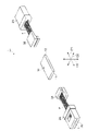
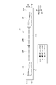
- FIG. 1 is a perspective view showing an optical wiring provided with an optical connection component according to the first embodiment.
- FIG. 2 is a view of the optical connection component according to the first embodiment as seen along the third direction.
- FIG. 3 is a view of the optical connection component according to the first embodiment as seen along the second direction.
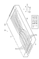
- FIG. 4 is a perspective view showing the optical connecting component according to the first embodiment.
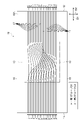
- FIG. 5 is a diagram for explaining the first order and the second order in the optical connection component according to the first embodiment.
- FIG. 6 is a diagram schematically showing the first order and the second order in the optical connection component according to the first embodiment.
- FIG. 7 is a view of the optical connection component according to the second embodiment as seen along the third direction.
- FIG. 8 is a view of the optical connection component according to the second embodiment as seen along the second direction.
- FIG. 9 is a perspective view showing an optical connection component according to the second embodiment.
- FIG. 10 is a view of the optical connection component according to the third embodiment as seen along the third direction.
- FIG. 11 is a view of the optical connection component according to the third embodiment as seen along the second direction.
- FIG. 12 is a perspective view showing an optical connecting component according to the third embodiment.
- FIG. 13 is a perspective view showing optical wiring provided with an optical connection component according to a fourth embodiment.
- FIG. 14 is a view of the optical wiring according to the fourth embodiment as seen along the second direction.
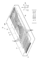
- FIG. 15 is a perspective view showing an MT ferrule and an optical fiber array for optical wiring according to the fourth embodiment.
- An object of the present disclosure is to provide an optical connection component that can be easily handled and that can suppress interference and loss of optical signals.
- An optical connection component includes: a plurality of cores for transmitting optical signals along a first direction; It is an optical connection component with a clad surrounding as .
- the optical connection component has a first surface extending in a second direction intersecting with the first direction, a third direction intersecting both the first direction and the second direction, and extending in the second direction and the third direction. a second surface present and aligned with the first surface along the first direction.
- Each of the plurality of cores extends from the first surface along the first direction, bends in the third direction, and extends to the second surface.
- a plurality of cores are arranged along the second direction on each of the first surface and the second surface.
- the order in which the plurality of cores are arranged as a whole on the first surface differs from the order in which the plurality of cores are arranged as a whole on the second surface.
- a plurality of cores are arranged on each of the first surface and the second surface.
- Each core extends from the first surface along the first direction, bends in the third direction, and extends to the second surface.
- the order in which the plurality of cores are arranged as a whole on the first surface differs from the order in which the plurality of cores are arranged as a whole on the second surface.
- the cores extending from the first surface are bent in the third direction, and the order of the cores is changed between the first surface and the second surface. Therefore, since the plurality of cores do not cross each other on the same plane, crosstalk and loss of optical signals passing through the cores can be suppressed.
- the parts for changing the order of the cores can be configured as a single part, the handling can be facilitated.
- the optical connection component described above may connect the first surface and the second surface to each other, and may have a third surface extending in the first direction and the second direction.
- a first distance from the third surface of the first surface to the plurality of cores and a second distance from the third surface of the second surface to the plurality of cores are different from each other, and the difference between the first distance and the second distance is It may be 10 ⁇ m or more.
- the bending length of the core in the third direction is 10 ⁇ m or more, so that crosstalk and loss of optical signals can be suppressed more reliably.
- the number of times each of the plurality of cores is bent in the third direction may be the same.
- the plurality of cores may constitute a first group including at least one core and a second group including cores not belonging to the first group. good.
- the order of arranging the cores of the first group on the first surface may be the same as the order of arranging the cores of the first group on the second surface, and the order of arranging the cores of the second group on the first surface may be the same as the order of arranging the cores of the second group on the first surface. It may be the same as the order in which the cores of the second group are arranged on the surface.
- each of the plurality of cores may be bent once in the third direction.
- a rearrangement section may be provided between the first surface and the second surface for changing the order of the plurality of cores in the second direction.
- the plurality of cores belonging to the first group are bent in the third direction between the first surface and the rearrangement portion, and the plurality of cores belonging to the second group are bent between the rearrangement portion and the second surface. may be bent in the third direction.
- the plurality of cores includes a first group including at least one core, a second group including cores not belonging to the first group, and the first group and a third group including cores that do not belong to the second group.
- the order in which the cores of the first group are arranged on the first surface may be the same as the order in which the cores of the first group are arranged on the second surface.
- the order in which the cores of the second group are arranged on the first surface may be the same as the order in which the cores of the second group are arranged on the second surface.
- the order in which the cores of the third group are arranged on the first surface may be the same as the order in which the cores of the third group are arranged on the second surface.
- a plurality of rearrangement portions for changing the order of the plurality of cores in the second direction may be provided between the first surface and the second surface.
- a rearrangement portion in which the cores belonging to the first group are bent in the second direction, a rearrangement portion in which the cores belonging to the second group are bent in the second direction, and a rearrangement portion belonging to the third group The rearranged portions in which the core is bent in the second direction may differ from each other in the first direction.
- a plurality of rearrangement portions for changing the order of the plurality of cores in the second direction may be provided between the first surface and the second surface.
- a rearrangement portion in which the cores belonging to the first group are bent in the second direction, a rearrangement portion in which the cores belonging to the second group are bent in the second direction, and a rearrangement portion belonging to the third group The rearranged portions in which the core is bent in the second direction may differ from each other in the third direction.
- An optical wiring according to one embodiment includes the optical connection component according to any one of (1) to (9) above, and at least one optical fiber holding a plurality of optical fibers optically connected to the cores of the optical connection component. and an optical fiber array.
- the optical wiring may include a plurality of optical fiber arrays.
- the optical wiring according to the above embodiment can facilitate handling and suppress interference and loss of optical signals.
- FIG. 1 is a perspective view showing an optical wiring 1 according to the first embodiment.
- the optical wiring 1 includes a first MT ferrule 2A, a second MT ferrule 2B, a first optical fiber array 3A, a second optical fiber array 3B, and an optical connection component 10.
- FIG. 1 the first MT ferrule 2A, the first optical fiber array 3A, the optical connection component 10, the second optical fiber array 3B and the second MT ferrule 2B are arranged in this order along the first direction D1.
- the optical connection component 10 transmits optical signals along the first direction D1.
- a first optical fiber array 3A and a second optical fiber array 3B are arranged between the first MT ferrule 2A and the second MT ferrule 2B.
- An optical connection component 10 is arranged between the first optical fiber array 3A and the second optical fiber array 3B.
- the first MT ferrule 2A holds a plurality of single core fibers F.
- the single-core fiber F has a tip face F1 exposed at the end face 2b of the first MT ferrule 2A directed in the first direction D1.
- the plurality of single-core fibers F belong to one of two groups (upper group, lower group). In each of the upper group and the lower group, the plurality of single-core fibers F are arranged along the second direction D2 intersecting the first direction D1.
- the upper set and the lower set are arranged along a third direction D3 intersecting the first direction D1 and the second direction D2.
- the second direction D2 is, for example, a direction orthogonal to the first direction D1
- the third direction D3 is orthogonal to both the first direction D1 and the second direction D2.
- the number of single-core fibers F arranged along the second direction D2 is, for example, twelve.
- the first MT ferrule 2A is a 24ch MT ferrule holding 24 single core fibers F.
- the first optical fiber array 3A holds multiple single-core fibers F extending from the first MT ferrule 2A.
- a plurality of single-core fibers F are arranged in a row along the second direction D2.
- a plurality of single-core fibers F extending from the first MT ferrule 2A are converted from being arranged in both the second direction D2 and the third direction D3 to being arranged in a line along the second direction D2.
- illustration of conversion of the state in which the single core fibers F are arranged is omitted.
- 24 single-core fibers F are arranged along the second direction D2.
- the configurations of the second MT ferrule 2B and the second optical fiber array 3B are the same as the configurations of the first MT ferrule 2A and the first optical fiber array 3A.
- the second MT ferrule 2B and the second optical fiber array 3B are arranged on the opposite side of the first MT ferrule 2A and the second optical fiber array 3B when viewed from the optical connection component 10 .
- the first MT ferrule 2A and the second MT ferrule 2B are arranged symmetrically with respect to the optical connecting component 10 .
- the first optical fiber array 3A and the second optical fiber array 3B are arranged symmetrically with respect to the optical connection component 10 .
- the optical connection component 10 has a first surface 11 facing the first optical fiber array 3A along the first direction D1 and a second surface 12 facing the second optical fiber array 3B along the first direction D1. have.
- the optical connection component 10 has, for example, a rectangular plate shape.
- Each of the first surface 11 and the second surface 12 extends in both the second direction D2 and the third direction D3.
- the second surface 12 is aligned with the first surface 11 along the first direction D1.
- FIG. 2 is a plan view of the optical connection component 10 when the optical connection component 10 is viewed along the third direction D3.
- FIG. 3 is a side view of the optical connection component 10 when the optical connection component 10 is viewed along the second direction D2.
- FIG. 4 is a perspective view of the optical connection component 10.
- the optical connection component 10 includes a first surface 11 and a second surface 12, a third surface 13 extending in the first direction D1 and the second direction D2, and a third surface 13 extending in the first direction D1 and the second direction D2.
- a fourth surface 14 facing the side opposite to the third surface 13, a fifth surface 15 extending in the first direction D1 and the third direction D3, and a sixth surface 16 facing the opposite side to the fifth surface 15 have.
- the optical connection component 10 includes a clad 10A and a plurality of cores 17 arranged inside the clad 10A and transmitting optical signals along the first direction D1.
- the core 17 is indicated by a solid line for easy understanding of the drawing.
- a plurality of cores 17 and clads 10A constitute a three-dimensional optical waveguide that transmits optical signals while bending them in the first direction D1, the second direction D2, and the third direction D3 in the cores 17 .
- the core 17 is produced, for example, by femtosecond laser irradiation.
- a plurality of cores 17 are arranged inside an integral clad 10A.
- Each of the plurality of cores 17 extends along the first direction D1 and is bent in the second direction D2 and the third direction D3.
- the number of times the cores 17 are bent in the third direction D3 is the same.
- the number of times that the plurality of cores 17 are bent in the third direction D3 is one. In this case, the number of times the core 17 bends can be minimized.
- the first distance K1 from the third surface 13 to the plurality of cores 17 on the first surface 11 is is different from the second distance K2 from the third surface 13 to the plurality of cores 17 in .
- the second distance K2 is longer than the first distance K1.
- a difference between the second distance K2 and the first distance K1 is, for example, 10 ⁇ m or more.
- a plurality of cores 17 are arranged along the second direction D2 on each of the first surface 11 and the second surface 12 .
- 24 cores 17 are arranged in a straight line along the second direction D2 on each of the first surface 11 and the second surface 12 .
- Each core 17 on the first surface 11 is optically connected to each single core fiber F of the first optical fiber array 3A.
- Each core 17 on the second surface 12 is optically connected to each single core fiber F of the second optical fiber array 3B.
- the order in which the plurality of cores 17 are arranged as a whole on the first surface 11 and the order in which the plurality of cores 17 are arranged as a whole on the second surface 12 are different from each other. That is, the order of the plurality of cores 17 is changed between the first surface 11 and the second surface 12 .
- the order in which the plurality of cores 17 are arranged as a whole on the first surface 11 may be referred to as a first order
- the order in which the plurality of cores 17 as a whole are arranged on the second surface 12 may be referred to as a second order.
- the optical connection component 10 is a three-dimensional optical waveguide for shuffling that changes the order of the cores 17 between the first surface 11 and the second surface 12 .
- "order" indicates the order in which cores or optical fibers are arranged in a given plane.
- the multiple cores 17 constitute a first group G1 and a second group G2 composed of multiple cores 17 that do not belong to the first group G1.
- the first order in each of the first group G1 and the second group G2 (the order of the cores 17 on the first surface 11), and the second order in each of the first group G1 and the second group G2 (the cores on the second surface 12 17) are identical to each other. That is, the order in which the cores 17 of the first group G1 are arranged on the first surface 11 is the same as the order in which the cores 17 of the first group G1 are arranged on the second surface 12 .
- the order in which the cores 17 of the second group G2 are arranged on the first surface 11 is the same as the order in which the cores 17 of the second group G2 are arranged on the second surface 12 .
- the first order from the fifth surface 15 side of the 24 cores 17 arranged on the first surface 11 is the first, second, third, .
- the even-numbered cores 17 are assumed to be the first group G1
- the odd-numbered cores 17 are assumed to be the second group G2.
- the first order of each of the 24 cores 17 is 1st, 2nd, 3rd... 23rd, 24th
- the second order is 2nd, 4th. . . . 24th, 1st, . . . 21st, 23rd. This will be described below with the first order being (1,2,3...23,24) and the second order being (2,4...24,1...21,23). It may be shown as
- the 2k ⁇ 1-th cores 17 from the fifth surface 15 of the first surface 11 are replaced with the ((n/2)+1)-th to n-th cores 17 on the second surface 12 . That is, the first order of the first faces 11 is (1, 2, 3 . . . n ⁇ 1, n), whereas the second order of the second faces 12 is (2, 4 . 1 . . . , n ⁇ 3, n ⁇ 1).
- the optical connection component 10 has a bending portion 18 that bends in the third direction D3, and a rearrangement portion 19 that bends the cores 17 in the second direction D2 to change the order of the plurality of cores 17 .
- the "bending portion” indicates the portion from the beginning of bending of the core 17 in the third direction D3 to the end of bending.
- a “rearranged portion” indicates a portion from the beginning of bending of the core 17 in the second direction D2 to the end of bending.
- the bending portion 18 and rearrangement portion 19 are provided between the first surface 11 and the second surface 12 .
- the rearrangement section 19 is provided in a region including the center of the optical connection component 10 in the first direction D1.
- the optical connection component 10 has a plurality of bends 18 . In this case, the positions of the bent portions 18 of the first group G1 and the positions of the bent portions 18 of the second group G2 are different from each other.
- the bending portion 18 of the first group G1 is located between the first surface 11 and the rearrangement portion 19.
- the bends 18 of the second group G2 are located between the rearrangement 19 and the second surface 12 . That is, the plurality of cores 17 belonging to the first group G1 are bent in the third direction D3 between the first surface 11 and the rearrangement portion 19, and the plurality of cores 17 belonging to the second group G2 are rearranged. It is bent in the third direction D3 between the portion 19 and the second surface 12 .
- the position of the bent portion 18 in the first direction D1 and the position of the rearrangement portion 19 in the first direction D1 are different from each other.
- the plurality of cores 17 inside the optical connection component 10 are configured so as not to come into contact with each other.
- 5 and 6 illustrate specific examples of the order of single-core fibers F in each of the first MT ferrule 2A, first optical fiber array 3A, optical connection component 10, second optical fiber array 3B, and second MT ferrule 2B.
- the first order of the first surfaces 11 of each of the plurality of cores 17 is (1, 2, 3 . . . 23, 24) and the second order of the second surfaces 12 is (2, 4 . 24, 1 . is.
- the order of the single core fibers F of the second optical fiber array 3B is (2, 4...24, 1...21, 23).
- the order (core number) of the single core fibers F is (1, 2 , 3...23, 24).
- the order (core numbers) of the single core fibers F is (2, 4 . . . ⁇ 24, 1 ... 21, 23).
- the order of the single-core fibers F in the first MT ferrule 2A and the order of the single-core fibers F in the second MT ferrule 2B are different from each other.
- the order of the single-core fibers F of the first optical fiber array 3A is (1, 2, 3 . . . 23, 24)
- the order is (2, 4, 6...22, 24) in the upper row and (1, 3, 5...21, 23) in the lower row.
- the single-core fibers F originally arranged in two stages in the first MT ferrule 2A are arranged in a row on the way to the first optical fiber array 3A.
- the single-core fibers F of the second optical fiber array 3B When the order of the single-core fibers F of the second optical fiber array 3B is (2, 4, 6...24, 1...21, 23), the single 18, 22, 1, . , 23). In this case, the single-core fibers F originally arranged in a line in the second optical fiber array 3B are divided into two stages on the way to the second MT ferrule 2B and reach the second MT ferrule 2B (virtual cross section (d)). do.
- the optical wiring 1 according to the present embodiment including the first MT ferrule 2A, the first optical fiber array 3A, the optical connection component 10, the second optical fiber array 3B and the second MT ferrule 2B all the single core fibers F can be shuffled.
- a plurality of cores 17 are arranged on each of the first surface 11 and the second surface 12 .
- Each core 17 extends from the first surface 11 along the first direction D1 and is bent in the third direction D3 to extend to the second surface 12 .
- the order in which the cores 17 are arranged on the first surface 11 as a whole (first order) is different from the order in which the cores 17 are arranged on the second surface 12 as a whole (second order). Since the plurality of cores 17 do not cross each other on the same plane, interference and loss of optical signals passing through the cores 17 can be suppressed. Further, since the component for changing the order of the cores 17 can be configured as a single component, the optical connection component 10, the handling can be facilitated.
- FIG. 7 is a plan view of the optical connecting component 20 as seen along the third direction D3.
- FIG. 8 is a side view of the optical connecting component 20 as seen along the second direction D2.
- FIG. 9 is a perspective view showing the optical connection component 20.
- the optical connection component 20 includes a clad 10A and a plurality of cores 27 arranged inside the clad 10A and transmitting optical signals along the first direction D1.
- the number of times that the multiple cores 27 are bent in the third direction D3 is two.
- twelve cores 27 are aligned along the second direction D2.
- the plurality of cores 27 includes a first group G1, a second group G2 composed of a plurality of cores 27 not belonging to the first group G1, and cores 27 not belonging to the first group G1 and the second group G2. constitute a third group G3.
- the first order (the order of the cores 27 on the first surface 11) in each of the first group G1, the second group G2 and the third group G3, and the first order in each of the first group G1, the second group G2 and the third group G3
- the second order (the order of the cores 27 on the second surface 12) is the same as each other.
- the order in which the cores 17 of the first group G1 are arranged on the first surface 11 is the same as the order in which the cores 17 of the first group G1 are arranged on the second surface 12 .
- the order in which the cores 17 of the second group G2 are arranged on the first surface 11 is the same as the order in which the cores 17 of the second group G2 are arranged on the second surface 12 .
- the order in which the cores 17 of the third group G3 are arranged on the first surface 11 is the same as the order in which the cores 17 of the third group G3 are arranged on the second surface 12 .
- the 3m ⁇ 2 (m is a natural number) core 27 from the fifth surface 15 side is the first group G1
- the 3m ⁇ 1th core 27 from the fifth surface 15 is the second group G2.
- the 3m-th core 27 from the fifth surface 15 are taken as a third group G3.
- the second order of the second faces 12 is switched to (3, 6, 9, 12, 2, 5, 8, 11, 1, 4, 7, 10).
- the 3q (q is a natural number of p/3 or less)-th core 27 from the fifth surface 15 of the first surface 11 is on the second surface 12
- the 1st to p/3th cores 27 are replaced on the 5th surface 15 of the first surface 11 to the 3q-1th cores 27 on the second surface 12 by (p/3)+1st to 2p/3th.
- the 3q-2th cores 27 from the fifth surface 15 of the first surface 11 are replaced with (2p/3)+1st to pth cores 27 on the second surface 12 .
- the optical connection component 20 includes a plurality of bent portions 28 that bend in the third direction D3, and rearrangement portions 29A, 29B, and 29C that bend the cores 27 in the second direction D2 to change the order of the plurality of cores 27.
- a rearrangement section 29A indicates a rearrangement section for the first group G1
- a rearrangement section 29B indicates a rearrangement section for the second group G2
- a rearrangement section 29C indicates a rearrangement section for the third group G3.
- the position of the rearrangement section 29A of the first group G1, the position of the rearrangement section 29B of the second group G2, and the position of the rearrangement section 29B of the third group G3 are different from each other.
- the positions of the plurality of bent portions 28 are different from each other.
- the bent portion 28 is between the first surface 11 and the rearrangement portion 29C, between the rearrangement portion 29C and the rearrangement portion 29B, between the rearrangement portion 29B and the rearrangement portion 29A, and between the rearrangement portion 29B and the rearrangement portion 29A. It is provided between 29A and the second surface 12, respectively.
- the distance from the third surface 13 of each core 27 is constant in each of the sorting section 29A, the sorting section 29B, and the sorting section 29C.
- the distance from the third surface 13 to each core 27 in each of the rearrangement portion 29A, the rearrangement portion 29B, and the rearrangement portion 29C is greater than the first distance K1 from the third surface 13 to the cores 27 on the first surface 11.
- the rearrangement section 29C is arranged closer to the first surface 11 than the rearrangement section 29B, and the rearrangement section 29A is arranged closer to the second surface 12 than the rearrangement section 29B.
- the cores 27 of the third group G3 extending from the first surface 11 are bent in the third direction D3 at the bending portion 28 and reach the sorting portion 29C.
- the cores 27 of the third group G3 that have reached the sorting section 29C are bent in the second direction D2, and the order of the cores 27 of the first group G1 and the cores 27 of the second group G2 is changed.
- the cores 27 of the third group G3 extending from the sorting portion 29C toward the second surface 12 extend toward the second surface 12 after reaching the bending portion 28 and being further bent in the third direction D3.
- the cores 27 of the second group G2 extending from the first surface 11 extend from the first surface 11 along the first direction D1, pass through the position of the sorting portion 29C near the third surface 13 as they are, and extend in the first direction D1.
- extending along The cores 27 of the second group G2 passing through the rearrangement portion 29C near the third surface 13 are bent in the third direction D3 at the bending portion 28 and reach the rearrangement portion 29B.
- the cores 27 of the second group G2 that have reached the sorting section 29B are bent in the second direction D2, and the order of the cores 27 of the first group G1 and the cores 27 of the third group G3 is changed.
- the cores 27 of the second group G2 extending from the sorting portion 29B toward the second surface 12 extend toward the second surface 12 after reaching the bending portion 28 and being bent in the third direction D3.
- the cores 27 of the first group G1 extending from the first surface 11 extend from the first surface 11 along the first direction D1, and are positioned near the third surface 13 of the rearrangement portion 29C and the third cores of the rearrangement portion 29B. It passes through the position near the surface 13 and extends along the first direction D1.
- the cores 27 of the first group G1 passing through the rearrangement portion 29B near the third surface 13 are bent in the third direction D3 at the bending portion 28 and reach the rearrangement portion 29A.
- the cores 27 of the first group G1 that have reached the rearrangement portion 29A are bent in the second direction D2, and the order of the cores 27 of the second group G2 and the cores 27 of the third group G3 is changed.
- the cores 27 of the first group G1 extending from the sorting portion 29A toward the second surface 12 reach the second surface 12 after reaching the bending portion 28 and being bent in the third direction D3.
- the positions at which the cores 27 are bent in the second direction D2 are different among the first group G1, the second group G2, and the third group G3.
- the cores 27 in the third group G3 are bent in the third direction D3 before the cores 27 in the second group G2, and the cores in the second group G2 27 are bent in the third direction D3 before the cores 27 of the first group G1. Therefore, a configuration is realized in which the plurality of cores 27 do not contact each other inside the optical connection component 20 .
- FIG. 10 is a plan view of the optical connecting component 30 as seen along the third direction D3.
- FIG. 11 is a side view of the optical connection component 30 as seen along the second direction D2.
- FIG. 12 is a perspective view showing the optical connection component 30.
- the same reference numerals will be used to denote the same descriptions as in the above-described embodiments, and the descriptions will be omitted as appropriate.
- the optical connection component 30 has a plurality of cores 37 arranged inside the clad 10A and transmitting optical signals along the first direction D1.
- the number of times the plurality of cores 37 are bent in the third direction D3 is one for the first group G1 and the third group G3, and two times for the second group G2.
- the number of times the cores 37 are bent in the third direction D3 is different from each other.
- the number of times is different for each group.
- the optical connection component 30 includes a plurality of bending portions 38 in which the cores 37 are bent in the third direction D3, rearrangement portions 39A, 39B in which the cores 37 are bent in the second direction D2 and the order of the plurality of cores 37 is changed. 39C.
- the bent portions 38 are provided between the first surface 11 and the rearranging portions 39A, 39B, 39C and between the rearranging portions 39A, 39B, 39C and the second surface 12, respectively.
- the rearrangement units 39A, 39B, and 39C are arranged on a plurality of planes different from each other.
- the rearranging portions 39A, 39B, and 39C have different distances from the third surface 13 . For example, the distance from the third surface 13 to the sorting section 39A of the first group G1 is shorter than the distance from the third surface 13 to the sorting section 39B of the second group G2.
- the distance from the third surface 13 to the rearrangement portion 39B of the second group G2 is shorter than the distance from the third surface 13 to the rearrangement portion 39C of the third group G3. Since the distance from the third surface 13 to the cores 37 differs for each group, for example, when the cores 37 are manufactured by irradiating the femtosecond laser along the third direction D3, the manufactured cores 37 become new cores 37. can be made out of the way during the fabrication of the
- the sorting section 39A is arranged at a position closer to the third surface 13 than the sorting section 39B.
- the sorting section 39B is arranged at a position closer to the third surface 13 than the sorting section 39C.
- the distance from the third surface 13 to the rearrangement portion 39A is the same as the first distance K1 from the third surface 13 to the core 37 of the first surface 11 .
- the distance from the third surface 13 to the rearrangement portion 39C is the same as the distance from the third surface 13 to the core 37 of the second surface 12 .
- the cores 37 of the third group G3 extending from the first surface 11 are bent in the third direction D3 at the bending portion 38 and reach the sorting portion 39C.
- the cores 37 of the third group G3 that have reached the rearrangement portion 39C are bent in the second direction D2, and the order of the cores 37 of the second group G2 and the cores 37 of the first group G1 is changed.
- the cores 37 of the third group G3 extend from the sorting portion 39C toward the second surface 12 along the first direction D1.
- the cores 37 of the second group G2 extending from the first surface 11 are bent in the third direction D3 at the bending portion 38 and reach the sorting portion 39B.
- the cores 37 of the second group G2 that have reached the sorting section 39B are bent in the second direction D2, and the order of the cores 37 of the first group G1 and the cores 37 of the third group G3 is changed.
- the cores 37 of the second group G2 are bent again in the third direction D3 at the bending portion 38 on the way from the sorting portion 39B to the second surface 12, and reach the second surface 12 after being bent in the third direction D3. do.
- the cores 37 of the first group G1 extending from the first surface 11 reach the rearranging portion 39A without being bent in the third direction D3 at the bending portion 38.
- the cores 37 of the first group G1 that have reached the sorting section 39A are bent in the second direction D2, and the order of the cores 37 of the second group G2 and the cores 37 of the third group G3 is changed.
- the cores 37 of the first group G1 are bent in the third direction D3 at the bending portion 38 on the way from the sorting portion 39A to the second surface 12, and reach the second surface 12 after being bent in the third direction D3. .
- the positions of the rearrangement portions 39A, 39B, and 39C in the third direction D3 are different for each of the first group G1, the second group G2, and the third group G3.
- the cores 37 of the third group G3 are bent in the third direction D3 with a larger curvature than the cores 37 of the second group G2, and the cores 37 of the first group G1 reaches the sorting section 39A without being bent in the third direction D3.
- the cores 37 of the first group G1 are bent in the third direction D3 with a larger curvature than the cores 37 of the second group G2 while heading toward the second surface 12 from each of the rearranging portions 39A, 39B, and 39C, Also, the cores 37 of the third group G3 reach the second surface 12 without being bent in the third direction D3. Therefore, a configuration is realized in which the plurality of cores 37 do not contact each other inside the optical connection component 30 .
- FIG. 13 is a perspective view showing an optical wiring 41 having an optical connection component 50.
- FIG. FIG. 14 is a side view of the optical wiring 41 viewed along the second direction D2.
- FIG. 15 is an enlarged perspective view of a portion of the optical wiring 41. As shown in FIG.
- the optical wiring 41 includes a plurality of first MT ferrules 2A, a plurality of second MT ferrules 2B, a plurality of first optical fiber arrays 3A, a plurality of second optical fiber arrays 3B, and an optical connection component 50.
- the plurality of first MT ferrules 2A, the plurality of first optical fiber arrays 3A, the optical connection component 50, the plurality of second optical fiber arrays 3B, and the plurality of second MT ferrules 2B are arranged in this order along the first direction D1. It is
- the optical connection component 50 like the optical connection components 10, 20, and 30, transmits optical signals along the first direction D1.
- the optical connecting component 50 has a first surface 11 and a second surface 12 .
- a plurality of first optical fiber arrays 3A are connected to the first surface 11, and a plurality of second optical fiber arrays 3B are connected to the second surface 12. As shown in FIG.
- Each of the plurality of first optical fiber arrays 3A and the plurality of second optical fiber arrays 3B are arranged along the second direction D2.
- tape fibers T each formed by bundling a plurality of single core fibers F are provided. be provided. That is, the first MT ferrule 2A and the first optical fiber array 3A and the second optical fiber array 3B and the second MT ferrule 2B are connected to each other via the tape fiber T, respectively.
- a plurality of tape fibers T extends from the first optical fiber array 3A.
- a first MT ferrule 2A is connected to each of a plurality of tape fibers T extending from the first optical fiber array 3A. That is, a plurality of first MT ferrules 2A are connected to one first optical fiber array 3A.
- the number of single core fibers F held by one tape fiber T is 24.
- first optical fiber array 3A is a 72ch optical fiber array
- three tape fibers T 72 single core fibers F
- four first optical fiber arrays 3A are connected to the first surface 11 and four second optical fiber arrays 3B are connected to the second surface 12 .
- the relationship between the second optical fiber array 3B and the second MT ferrule 2B is, for example, the same as the relationship between the first optical fiber array 3A and the first MT ferrule 2A.
- the optical wiring 41 including the plurality of first MT ferrules 2A, the plurality of first optical fiber arrays 3A, the optical connection component 50, the plurality of second optical fiber arrays 3B, and the plurality of second MT ferrules 2B explained. From the optical wiring 41 according to the fourth embodiment, the same effect as the optical wiring according to each of the above-described embodiments can be obtained.
- optical connection component with two or three groups containing multiple cores have been described. However, it may be an optical connection component with four or more groups. Moreover, it may be an optical connection component that does not have a group.
- Reference Signs List 1 41 Optical wiring 2A First MT ferrule 2B Second MT ferrule 2b End surface 3A First optical fiber array 3B Second optical fiber array 10, 20, 30, 50 Optical connection component 10A Cladding 11 Second First surface 12 Second surface 13 Third surface 14 Fourth surface 15 Fifth surface 16 Sixth surface 17, 27, 37 Cores 18, 28, 38 Bent portions 19, 29A, 29B, 29C, 39A, 39B, 39C Rearranging portion D1 First direction D2 Second direction D3 Third direction F Single core fiber F1 Tip surface G1 First group G2 Second group G3 Third group K1 First distance K2... Second distance T... Tape fiber
Landscapes
- Physics & Mathematics (AREA)
- General Physics & Mathematics (AREA)
- Optics & Photonics (AREA)
- Engineering & Computer Science (AREA)
- Microelectronics & Electronic Packaging (AREA)
- Mechanical Coupling Of Light Guides (AREA)
Abstract
Description
本出願は、2021年5月24日の日本出願第2021-087089号に基づく優先権を主張し、前記日本出願に記載された全ての記載内容を援用するものである。
最初に本開示の実施態様を列記して説明する。(1)一実施形態に係る光接続部品は、第1方向に沿って光信号を伝送する複数のコアと、前記複数のコアの屈折率よりも小さな屈折率を有し前記複数のコアを一体として囲むクラッドを備えた光接続部品である。光接続部品は、第1方向に交差する第2方向、及び、第1方向及び第2方向の双方に交差する第3方向に延在する第1面と、第2方向及び第3方向に延在すると共に、第1方向に沿って第1面に並ぶ第2面と、を有する。複数のコアのそれぞれは、第1面から、第1方向に沿って延び第3方向に曲げられて第2面まで延在している。第1面及び第2面のそれぞれにおいて、複数のコアが第2方向に沿って並んでいる。第1面における複数のコアが全体として並ぶ順序と、第2面における複数のコアが全体として並ぶ順序とが互いに異なる。
本開示に係る光接続部品及び光配線の具体例を、以下で図面を参照しながら説明する。なお、本発明は、以下の例示に限定されるものではなく、請求の範囲に示され、請求の範囲と均等の範囲における全ての変更が含まれることが意図される。図面の説明において同一または相当する要素には同一の符号を付し、重複する説明を適宜省略する。図面は、理解の容易化のため、一部を簡略化または誇張して描いている場合があり、寸法比率等は図面に記載のものに限定されない。
図1は、第1実施形態に係る光配線1を示す斜視図である。図1に示されるように、光配線1は、第1MTフェルール2Aと、第2MTフェルール2Bと、第1光ファイバアレイ3Aと、第2光ファイバアレイ3Bと、光接続部品10とを備える。例えば、第1MTフェルール2A、第1光ファイバアレイ3A、光接続部品10、第2光ファイバアレイ3B及び第2MTフェルール2Bは、この順で第1方向D1に沿って並んでいる。
次に、第2実施形態に係る光接続部品20について図7~図9を参照しながら説明する。図7は、光接続部品20を第3方向D3に沿って見た平面図である。図8は、光接続部品20を第2方向D2に沿って見た側面図である。図9は、光接続部品20を示す斜視図である。光接続部品20の一部の構成は、光接続部品10の一部の構成と重複するため、光接続部品10の構成と重複する部分については同一の符号を付して説明を適宜省略する。
続いて、第3実施形態に係る光接続部品30について図10~図12を参照しながら説明する。図10は、光接続部品30を第3方向D3に沿って見た平面図である。図11は、光接続部品30を第2方向D2に沿って見た側面図である。図12は、光接続部品30を示す斜視図である。以下では、前述した各実施形態と重複する説明を、同一の符号を付して適宜省略する。
次に、第4実施形態に係る光配線41及び光接続部品50について図13~図15を参照しながら説明する。図13は、光接続部品50を備えた光配線41を示す斜視図である。図14は、光配線41を第2方向D2に沿って見た側面図である。図15は、光配線41の一部を拡大した斜視図である。
2A…第1MTフェルール
2B…第2MTフェルール
2b…端面
3A…第1光ファイバアレイ
3B…第2光ファイバアレイ
10,20,30,50…光接続部品
10A…クラッド
11…第1面
12…第2面
13…第3面
14…第4面
15…第5面
16…第6面
17,27,37…コア
18, 28,38…曲げ部
19,29A,29B,29C,39A,39B,39C…並べ替え部
D1…第1方向
D2…第2方向
D3…第3方向
F…シングルコアファイバ
F1…先端面
G1…第1グループ
G2…第2グループ
G3…第3グループ
K1…第1距離
K2…第2距離
T…テープファイバ
Claims (11)
- 第1方向に沿って光信号を伝送する複数のコアと、前記複数のコアの屈折率よりも小さな屈折率を有し前記複数のコアを一体として囲むクラッドを備えた光接続部品であって、
前記第1方向に交差する第2方向、及び、前記第1方向及び前記第2方向の双方に交差する第3方向に延在する第1面と、
前記第2方向及び前記第3方向に延在すると共に、前記第1方向に沿って前記第1面に並ぶ第2面と、
を有し、
前記複数のコアのそれぞれは、前記第1面から、前記第1方向に沿って延び前記第3方向に曲げられて前記第2面まで延在しており、
前記第1面及び前記第2面のそれぞれにおいて、前記複数のコアが前記第2方向に沿って並んでおり、
前記第1面における前記複数のコアが全体として並ぶ順序と、
前記第2面における前記複数のコアが全体として並ぶ順序とが互いに異なる、
光接続部品。 - 前記第1面及び前記第2面を互いに接続すると共に、前記第1方向及び前記第2方向に延在する第3面を有し、
前記第1面における前記第3面から前記複数のコアまでの第1距離と、前記第2面における前記第3面から前記複数のコアまでの第2距離とが互いに異なり、
前記第1距離と前記第2距離との差が10μm以上である、
請求項1に記載の光接続部品。 - 前記複数のコアのそれぞれにおける前記第3方向に曲げられる回数が互いに同一である、
請求項1または請求項2に記載の光接続部品。 - 前記複数のコアは、前記複数のコアのうち少なくとも1つのコアを含む第1グループ、及び前記複数のコアのうち前記第1グループには属さないコアを含む第2グループを構成し、
前記第1面における前記第1グループのコアが並ぶ順序が、前記第2面における前記第1グループのコアが並ぶ順序と同一であり、
前記第1面における前記第2グループのコアが並ぶ順序が、前記第2面における前記第2グループのコアが並ぶ順序と同一である、
請求項1から請求項3のいずれか一項に記載の光接続部品。 - 前記複数のコアのそれぞれにおける前記第3方向に曲げられる回数が1回である、
請求項4に記載の光接続部品。 - 前記第1面と前記第2面との間に、前記複数のコアの前記第2方向の順序が変えられる並べ替え部が設けられており、
前記第1グループに属する前記複数のコアは、前記第1面と前記並べ替え部との間において前記第3方向に曲げられており、
前記第2グループに属する前記複数のコアは、前記並べ替え部と前記第2面との間において前記第3方向に曲げられている、
請求項4または請求項5に記載の光接続部品。 - 前記複数のコアは、前記複数のコアのうち少なくとも1つのコアを含む第1グループ、前記複数のコアのうち前記第1グループには属さないコアを含む第2グループ、並びに、前記複数のコアのうち前記第1グループ及び前記第2グループには属さないコアを含む第3グループを構成し、
前記第1面における前記第1グループのコアが並ぶ順序が、前記第2面における前記第1グループのコアが並ぶ順序と同一であり、
前記第1面における前記第2グループのコアが並ぶ順序が、前記第2面における前記第2グループのコアが並ぶ順序と同一であり、
前記第1面における前記第3グループのコアが並ぶ順序が、前記第2面における前記第3グループのコアが並ぶ順序と同一である、
請求項1から請求項3のいずれか一項に記載の光接続部品。 - 前記第1面と前記第2面との間に、前記複数のコアの前記第2方向の順序が変えられる複数の並べ替え部が設けられており、
前記複数の並べ替え部のうち、前記第1グループに属するコアが前記第2方向に曲げられた並べ替え部、前記第2グループに属するコアが前記第2方向に曲げられた並べ替え部、及び前記第3グループに属するコアが前記第2方向に曲げられた並べ替え部の位置が前記第1方向において互いに異なる、
請求項7に記載の光接続部品。 - 前記第1面と前記第2面との間に、前記複数のコアの前記第2方向の順序が変えられる複数の並べ替え部が設けられており、
前記複数の並べ替え部のうち、前記第1グループに属するコアが前記第2方向に曲げられた並べ替え部、前記第2グループに属するコアが前記第2方向に曲げられた並べ替え部、及び前記第3グループに属するコアが前記第2方向に曲げられた並べ替え部が前記第3方向において互いに異なる、
請求項7に記載の光接続部品。 - 請求項1から請求項9のいずれか一項に記載の光接続部品と、
前記光接続部品の前記複数のコアに光接続する複数の光ファイバを保持する少なくとも一つの光ファイバアレイと、
を備える光配線。 - 前記少なくとも一つの光ファイバアレイは、複数の光ファイバアレイである、
請求項10に記載の光配線。
Priority Applications (2)
| Application Number | Priority Date | Filing Date | Title |
|---|---|---|---|
| CN202280032390.3A CN117242382A (zh) | 2021-05-24 | 2022-05-06 | 光连接部件以及光布线 |
| JP2023523391A JPWO2022249868A1 (ja) | 2021-05-24 | 2022-05-06 |
Applications Claiming Priority (2)
| Application Number | Priority Date | Filing Date | Title |
|---|---|---|---|
| JP2021-087089 | 2021-05-24 | ||
| JP2021087089 | 2021-05-24 |
Publications (1)
| Publication Number | Publication Date |
|---|---|
| WO2022249868A1 true WO2022249868A1 (ja) | 2022-12-01 |
Family
ID=84229920
Family Applications (1)
| Application Number | Title | Priority Date | Filing Date |
|---|---|---|---|
| PCT/JP2022/019607 WO2022249868A1 (ja) | 2021-05-24 | 2022-05-06 | 光接続部品及び光配線 |
Country Status (3)
| Country | Link |
|---|---|
| JP (1) | JPWO2022249868A1 (ja) |
| CN (1) | CN117242382A (ja) |
| WO (1) | WO2022249868A1 (ja) |
Citations (8)
| Publication number | Priority date | Publication date | Assignee | Title |
|---|---|---|---|---|
| JP2005031185A (ja) * | 2003-07-08 | 2005-02-03 | Fuji Xerox Co Ltd | 積層型高分子導波路及びその製造方法 |
| JP2005043650A (ja) * | 2003-07-22 | 2005-02-17 | Fuji Xerox Co Ltd | クロスコネクト光配線シート及びその製造方法 |
| CN102902024A (zh) * | 2012-09-29 | 2013-01-30 | 华中科技大学 | 实现多芯光纤和光电子芯片阵列光耦合的方法 |
| CN103076659A (zh) * | 2013-01-11 | 2013-05-01 | 武汉邮电科学研究院 | 多芯光纤光互联结构 |
| JP2015106099A (ja) * | 2013-12-02 | 2015-06-08 | 住友ベークライト株式会社 | 光配線部品、光モジュール、光電気混載基板および電子機器 |
| JP2016133656A (ja) * | 2015-01-20 | 2016-07-25 | 株式会社日立製作所 | 光配線構造およびそれを備える情報処理装置 |
| JP2017534926A (ja) * | 2014-11-11 | 2017-11-24 | フィニサー コーポレイション | 2段の断熱結合されたフォトニック・システム |
| JP2020166233A (ja) * | 2019-03-26 | 2020-10-08 | 株式会社フジクラ | 導波路基板、光コネクタ、及び導波路基板の製造方法 |
-
2022
- 2022-05-06 WO PCT/JP2022/019607 patent/WO2022249868A1/ja active Application Filing
- 2022-05-06 JP JP2023523391A patent/JPWO2022249868A1/ja active Pending
- 2022-05-06 CN CN202280032390.3A patent/CN117242382A/zh active Pending
Patent Citations (8)
| Publication number | Priority date | Publication date | Assignee | Title |
|---|---|---|---|---|
| JP2005031185A (ja) * | 2003-07-08 | 2005-02-03 | Fuji Xerox Co Ltd | 積層型高分子導波路及びその製造方法 |
| JP2005043650A (ja) * | 2003-07-22 | 2005-02-17 | Fuji Xerox Co Ltd | クロスコネクト光配線シート及びその製造方法 |
| CN102902024A (zh) * | 2012-09-29 | 2013-01-30 | 华中科技大学 | 实现多芯光纤和光电子芯片阵列光耦合的方法 |
| CN103076659A (zh) * | 2013-01-11 | 2013-05-01 | 武汉邮电科学研究院 | 多芯光纤光互联结构 |
| JP2015106099A (ja) * | 2013-12-02 | 2015-06-08 | 住友ベークライト株式会社 | 光配線部品、光モジュール、光電気混載基板および電子機器 |
| JP2017534926A (ja) * | 2014-11-11 | 2017-11-24 | フィニサー コーポレイション | 2段の断熱結合されたフォトニック・システム |
| JP2016133656A (ja) * | 2015-01-20 | 2016-07-25 | 株式会社日立製作所 | 光配線構造およびそれを備える情報処理装置 |
| JP2020166233A (ja) * | 2019-03-26 | 2020-10-08 | 株式会社フジクラ | 導波路基板、光コネクタ、及び導波路基板の製造方法 |
Also Published As
| Publication number | Publication date |
|---|---|
| CN117242382A (zh) | 2023-12-15 |
| JPWO2022249868A1 (ja) | 2022-12-01 |
Similar Documents
| Publication | Publication Date | Title |
|---|---|---|
| US6045269A (en) | Multicore optical connector and method of producing the connector | |
| EP2793412B1 (en) | Bi-directional optical communication method and multi-core optical fiber | |
| CN102681119B (zh) | 光纤缆线以及光纤带 | |
| JP4618446B2 (ja) | 光学素子、光学系及び導波路 | |
| JP5235125B2 (ja) | 光ファイバテープ及び光ファイバケーブル | |
| KR20060085557A (ko) | 광섬유 전력 분할기 모듈 장치 | |
| JP2017187644A (ja) | 光配線接続部材 | |
| US5020871A (en) | Optical fiber wiring apparatus | |
| WO2018135411A1 (ja) | 光導波路部材及び光結合構造 | |
| WO2022176978A1 (ja) | 光入出力装置 | |
| WO2019210763A1 (zh) | 一种光纤插芯、光纤连接器 | |
| JP2013160800A (ja) | マルチコア光ファイバテープ | |
| JP2018041034A (ja) | 光コネクタ及び光接続構造 | |
| EP2601549B1 (en) | Optical coupling system | |
| WO2022249868A1 (ja) | 光接続部品及び光配線 | |
| WO2023062923A1 (ja) | ファイバ集合体、及び、ファイバ集合体の製造方法 | |
| JP3853600B2 (ja) | 光ファイバシートの配線方法および光ファイバシート | |
| JP2011203527A (ja) | 光学素子モジュール | |
| JP2021018380A (ja) | マルチコアファイバの光接続構造 | |
| JP2004086069A (ja) | 多心光フェルール、多心光コネクタ、及び光モジュール | |
| JP2003131046A (ja) | 光配線接続構造 | |
| WO2021210529A1 (ja) | 光路変換部品付き回路基板及び回路基板搭載用配線モジュール | |
| JP2015094838A (ja) | 光信号接続部材 | |
| WO2022249903A1 (ja) | 光接続部品及び光接続構造 | |
| JP2935442B2 (ja) | 多心マトリクス光ファイバスイッチ |
Legal Events
| Date | Code | Title | Description |
|---|---|---|---|
| 121 | Ep: the epo has been informed by wipo that ep was designated in this application |
Ref document number: 22811141 Country of ref document: EP Kind code of ref document: A1 |
|
| WWE | Wipo information: entry into national phase |
Ref document number: 2023523391 Country of ref document: JP |
|
| WWE | Wipo information: entry into national phase |
Ref document number: 18287499 Country of ref document: US |
|
| WWE | Wipo information: entry into national phase |
Ref document number: 202280032390.3 Country of ref document: CN |
|
| NENP | Non-entry into the national phase |
Ref country code: DE |
|
| 122 | Ep: pct application non-entry in european phase |
Ref document number: 22811141 Country of ref document: EP Kind code of ref document: A1 |