WO2023281768A1 - フィルタユニット - Google Patents
フィルタユニット Download PDFInfo
- Publication number
- WO2023281768A1 WO2023281768A1 PCT/JP2021/045982 JP2021045982W WO2023281768A1 WO 2023281768 A1 WO2023281768 A1 WO 2023281768A1 JP 2021045982 W JP2021045982 W JP 2021045982W WO 2023281768 A1 WO2023281768 A1 WO 2023281768A1
- Authority
- WO
- WIPO (PCT)
- Prior art keywords
- shape
- filter
- filter unit
- tip
- retaining
- Prior art date
- Legal status (The legal status is an assumption and is not a legal conclusion. Google has not performed a legal analysis and makes no representation as to the accuracy of the status listed.)
- Ceased
Links
Images




Classifications
-
- B—PERFORMING OPERATIONS; TRANSPORTING
- B01—PHYSICAL OR CHEMICAL PROCESSES OR APPARATUS IN GENERAL
- B01D—SEPARATION
- B01D46/00—Filters or filtering processes specially modified for separating dispersed particles from gases or vapours
- B01D46/52—Particle separators, e.g. dust precipitators, using filters embodying folded corrugated or wound sheet material
- B01D46/521—Particle separators, e.g. dust precipitators, using filters embodying folded corrugated or wound sheet material using folded, pleated material
-
- B—PERFORMING OPERATIONS; TRANSPORTING
- B01—PHYSICAL OR CHEMICAL PROCESSES OR APPARATUS IN GENERAL
- B01D—SEPARATION
- B01D46/00—Filters or filtering processes specially modified for separating dispersed particles from gases or vapours
- B01D46/42—Auxiliary equipment or operation thereof
-
- B—PERFORMING OPERATIONS; TRANSPORTING
- B01—PHYSICAL OR CHEMICAL PROCESSES OR APPARATUS IN GENERAL
- B01D—SEPARATION
- B01D46/00—Filters or filtering processes specially modified for separating dispersed particles from gases or vapours
- B01D46/52—Particle separators, e.g. dust precipitators, using filters embodying folded corrugated or wound sheet material
-
- B—PERFORMING OPERATIONS; TRANSPORTING
- B01—PHYSICAL OR CHEMICAL PROCESSES OR APPARATUS IN GENERAL
- B01D—SEPARATION
- B01D46/00—Filters or filtering processes specially modified for separating dispersed particles from gases or vapours
- B01D46/88—Replacing filter elements
-
- F—MECHANICAL ENGINEERING; LIGHTING; HEATING; WEAPONS; BLASTING
- F24—HEATING; RANGES; VENTILATING
- F24F—AIR-CONDITIONING; AIR-HUMIDIFICATION; VENTILATION; USE OF AIR CURRENTS FOR SCREENING
- F24F13/00—Details common to, or for air-conditioning, air-humidification, ventilation or use of air currents for screening
- F24F13/28—Arrangement or mounting of filters
-
- F—MECHANICAL ENGINEERING; LIGHTING; HEATING; WEAPONS; BLASTING
- F24—HEATING; RANGES; VENTILATING
- F24F—AIR-CONDITIONING; AIR-HUMIDIFICATION; VENTILATION; USE OF AIR CURRENTS FOR SCREENING
- F24F8/00—Treatment, e.g. purification, of air supplied to human living or working spaces otherwise than by heating, cooling, humidifying or drying
- F24F8/10—Treatment, e.g. purification, of air supplied to human living or working spaces otherwise than by heating, cooling, humidifying or drying by separation, e.g. by filtering
- F24F8/108—Treatment, e.g. purification, of air supplied to human living or working spaces otherwise than by heating, cooling, humidifying or drying by separation, e.g. by filtering using dry filter elements
-
- F—MECHANICAL ENGINEERING; LIGHTING; HEATING; WEAPONS; BLASTING
- F24—HEATING; RANGES; VENTILATING
- F24F—AIR-CONDITIONING; AIR-HUMIDIFICATION; VENTILATION; USE OF AIR CURRENTS FOR SCREENING
- F24F8/00—Treatment, e.g. purification, of air supplied to human living or working spaces otherwise than by heating, cooling, humidifying or drying
- F24F8/80—Self-contained air purifiers
-
- B—PERFORMING OPERATIONS; TRANSPORTING
- B01—PHYSICAL OR CHEMICAL PROCESSES OR APPARATUS IN GENERAL
- B01D—SEPARATION
- B01D2271/00—Sealings for filters specially adapted for separating dispersed particles from gases or vapours
- B01D2271/02—Gaskets, sealings
Definitions
- the present invention relates to filter units used in air cleaners.
- Patent Document 1 discloses an air purifier and a filter.
- An air purifier sucks air with a fan. The sucked air is cleaned by passing through a filter inside the air purifier and then discharged.
- the filter is arranged inside the air purifier in a state in which a bellows-folded HEPA filter is bent at two points to form a U-shape.
- the filter is provided with retaining frames at both ends of the filter in the direction in which the fold extends (hereinafter referred to as the fold direction) for suppressing the widening of the fold of the bellows fold.
- both ends in the direction perpendicular to the crease direction may roll up during use.
- An object of the present invention is to provide a filter unit that can reduce deformation and suppress deterioration of the air cleaning function.
- a filter unit is a filter having a bellows-folded shape, and includes a first portion and a second direction crossing the first direction from one end of the first portion in the first direction. and a third part extending from the end of the first part on the other side in the first direction to one side in a third direction intersecting the first direction , the second part and the third part are on one side of the first part in an orthogonal direction perpendicular to the first part and face the first direction, and the first part and the second part , and the fold direction, which is the direction in which the folds of the bellows folds of the third portion extend, are perpendicular to the first direction, the second direction, and the third direction, and the fold direction of the filter and the filter.
- a first shape-retaining member that retains the shape of the filter, a second tip that is one end of the second part in the second direction, and the third part a second shape-retaining member provided at least on a portion of each of the third distal ends, which are ends on one side in the third direction, excluding both ends in the crease direction, and retaining the shape of the filter; characterized by comprising
- the filter unit has a second shape-retaining member that retains the shape of the filter at the second tip and the third tip corresponding to the ends of the filter in the direction orthogonal to the fold direction of the bellows fold. Therefore, the filter unit can reduce the possibility that both ends of the filter in the direction perpendicular to the fold direction will be rolled up during use, thereby preventing deformation of the filter and suppressing deterioration of the air cleaning function.
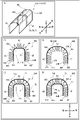
- FIG. 10 is a diagram showing second shape-retaining members 7A to 7D;
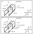
- FIG. 10 is a diagram showing second shape-retaining members 7E to 7H;
- FIG. 10 is a diagram showing second shape-retaining members 7E to 7H;
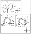
- FIG. 10 is a diagram showing second shape-retaining members 7I and 7J;
- FIG. 10 is a diagram showing second shape-retaining members 7K and 7L;
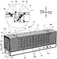
- FIG. 10 is a diagram showing second shape-retaining members 7M and 7N; It is a perspective view of the air cleaner 1B.
- FIG. 1 An air purifier 1A and a filter unit 6, which are one embodiment of the present invention, will be described.
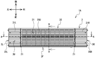
- Upper, lower, right, left, lower left, and upper right in FIG. 1 are respectively upper, lower, front, rear, left, and right of the air cleaner 1A.
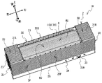
- Upper, lower, lower right, upper left, lower left, and upper right in FIG. 3 are respectively upper, lower, front, rear, left, and right of the filter unit 6 .
- the air purifier 1A sucks in the surrounding air.
- the air sucked inside is purified by passing through the filter unit 6 attached to the air cleaner 1A.
- the cleaned air is blown out from the air cleaner 1A.
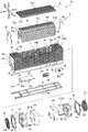
- the air purifier 1A includes a housing 2 (see FIGS. 1 to 3), a lid 31 (see FIGS. 1 and 2), and fans 5L and 5R (generally referred to as “fans 5”; see FIGS. 4 and 6). , and a control board 9 (see FIG. 6).
- the housing 2 has a substantially hexahedral shape, more specifically, a substantially rectangular parallelepiped elongated in the left-right direction.
- the housing 2 has a pedestal 3B (see FIGS. 1 and 3), a front wall 3F, a rear wall 3S, a left wall 3L, a right wall 3R (see FIGS. 2 and 3), and an upper wall 3U.
- the pedestal 3B has a substantially box-like shape, and a space for accommodating the control board 9 (see FIG. 6) and the like is formed inside.
- the front wall 3F, the rear wall 3S, the left wall 3L, and the right wall 3R each have a plate shape and are connected to the upper wall 30 (see FIG. 6) of the pedestal 3B.
- the front wall 3F, rear wall 3S, left wall 3L, and right wall 3R extend upward from the front end, rear end, left end, and right end of the upper wall 30 of the pedestal 3B, respectively.
- the upper wall 3U has a plate shape and is connected to upper ends of the front wall 3F, the rear wall 3S, the left wall 3L, and the right wall 3R.
- An internal space surrounded by the front wall 3F, the rear wall 3S, the left wall 3L, the right wall 3R, the upper wall 3U, and the upper wall 30 of the pedestal 3B is called a cavity 10 (see FIG. 3).
- the upper wall 3U includes an upper left wall 31L and an upper right wall 31R.
- the upper left wall 31L is provided near the left end of the upper ends of the front wall 3F and the rear wall 3S and between the upper ends of the left wall 3L.
- the upper right wall 31R is provided near the right end of the upper ends of the front wall 3F and the rear wall 3S and between the upper ends of the right wall 3R.
- the right end of the upper left wall 31L, the left end of the upper right wall 31R, and the upper ends of the front wall 3F and the rear wall 3S form rectangular openings 21.
- Opening 21 opens cavity 10 .
- the lid 31 has a plate shape. The lid 31 closes the opening 21 while attached to the opening 21 . On the other hand, when the lid 31 is removed from the opening 21, the opening 21 opens the cavity 10 as shown in FIG.
- partition walls 36L and 36R are provided on the upper wall 30 of the base 3B.
- the partition wall 36L is provided below the left end of the opening 21 (see FIG. 3).
- the partition wall 36R is provided below the right end of the opening 21 (see FIG. 3).
- the partition walls 36L and 36R are perpendicular to the left-right direction.
- a plurality of slit-shaped through holes are formed in the partition walls 36L and 36R.
- the partition walls 36L, 36R partition the cavity 10 into three parts (cavities 10U, 10L, 10R).
- the hollow portion 10L is a portion of the hollow portion 10 to the left of the partition wall 36L.
- the hollow portion 10R is a portion of the hollow portion 10 to the right of the partition wall 36R.
- the hollow portion 10U is a portion of the hollow portion 10 that is sandwiched between the partition walls 36L and 36R from the left and right directions, and is positioned below the lid 31 in the attached state.
- a filter unit 6 and blowers 5L and 5R, which will be described later, are housed in the hollow portions 10U, 10L and 10R, respectively.
- the lid 31 is formed with a suction port 20U.
- a suction port 20F is formed in a portion of the front wall 3F that overlaps the opening 21 in the left-right direction.
- a suction port 20S (see FIG. 3) is formed in a portion of the rear wall 3S that overlaps the opening 21 in the left-right direction.
- Each of the suction ports 20U, 20F, and 20S consists of a plurality of slit-shaped through holes.
- openings 20L and 20R are formed in the left and right ends of the housing 2, respectively.
- the opening 20L is surrounded by left end portions of the upper wall 3U, the front wall 3F, the rear wall 3S, and the upper wall 30 of the pedestal 3B.
- the opening 20L communicates with the cavity 10L (see FIG. 4).
- the opening 20R is surrounded by right end portions of the upper wall 3U, the front wall 3F, the rear wall 3S, and the upper wall 30 of the pedestal 3B.
- the opening 20R communicates with the cavity 10R (see FIG. 4).
- the openings 20L and 20R face each other in the left-right direction.
- the left wall 3L fits into the opening 20L
- the right wall 3R fits into the opening 20R.
- 22 L of circular outlets are provided in 3 L of left walls.
- a circular outlet 22R is provided on the right wall 3R.
- a louver 23 is fitted to each of the outlets 22L and 22R.
- the louver 23 has a plurality of blades 23A arranged in parallel.
- the louver 23 changes the direction of the air flowing through the gaps between the plurality of blades 23A to a direction inclined with respect to the left-right direction.
- the louver 23 can rotate with respect to the left wall 3L or the right wall 3R by sliding with respect to the outlets 22L and 22R.
- the filter unit 6 cleans the air by removing dirt, dust, and the like.
- the filter unit 6 has a filter 60.
- FIG. Filter 60 is a HEPA filter.
- the filter 60 has a bellows-like shape, in which mountain folds and valley folds are repeatedly formed on a thick plate-like filter base material.
- the filter 60 has a first portion 6U, a second portion 6F, a third portion 6S, a second bent portion 60F, and a third bent portion 60S.
- the first portion 6U, the second portion 6F, and the third portion 6S extend in the left-right direction.
- the first portion 6U is perpendicular to the vertical direction.
- a second bent portion 60F is connected to the front end portion of the first portion 6U.
- the second bent portion 60F extends forward from a connection portion with the first portion 6U while curving downward.
- a third bent portion 60S is connected to the rear end portion of the first portion 6U.
- the third bent portion 60S extends backward from a connection portion with the first portion 6U while curving downward.
- the second part 6F extends downward from the lower end of the second bent part 60F. That is, the second portion 6F is connected to the first portion 6U via the second bent portion 60F and extends downward from the vicinity of the front end portion of the first portion 6U.
- the third portion 6S extends downward from the lower end portion of the third bent portion 60S. That is, the third portion 6S is connected to the first portion 6U via the third bent portion 60S and extends downward from the vicinity of the rear end portion of the first portion 6U.
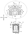
- the second portion 6F and the third portion 6S face each other in the front-rear direction below the first portion 6U. As shown in FIG. 5, the cross-sectional shape of the filter 60 taken along a plane perpendicular to the left-right direction is substantially U-shaped.
- the plurality of bellows folds formed in each of the first portion 6U, the second portion 6F, the third portion 6S, the second bent portion 60F, and the third bent portion 60S extend in the left-right direction, and It is perpendicular to the front-rear direction and the up-down direction.
- Regions below the first portion 6U, rearward of the second portion 6F, and frontward of the third portion 6S, that is, the first portion 6U, the second portion 6F, the third portion 6S, the second bend A region surrounded by the portion 60F and the third bent portion 60S is called an internal region 600.
- the edge portion adjacent to the inner region 600 is called an inner edge Ei, and is opposite to the inner edge Ei.
- the side is called the outer edge Eo.
- the inner edge Ei is a plurality of creases of the first part 6U, the second part 6F, the third part 6S, the second bent part 60F, and the third bent part 60S that are close to the inner region 600 among the plurality of folds of the bellows folds.
- extending along an imaginary line connecting the folds of Outer edge Eo is a plurality of creases separated from inner region 600 among a plurality of creases of bellows fold of each of first portion 6U, second portion 6F, third portion 6S, second bent portion 60F, and third bent portion 60S. extending along an imaginary line connecting the folds of
- each of the second bent portion 60F and the third bent portion 60S is arranged in the inner region 600. Therefore, the inner edge Ei of each of the second bent portion 60F and the third bent portion 60S corresponds to the edge near the center of curvature of each of the second bent portion 60F and the third bent portion 60S.
- An outer edge Eo of each of the second bent portion 60F and the third bent portion 60S corresponds to an edge separated from the center of curvature of each of the second bent portion 60F and the third bent portion 60S.
- the first part 6U, the second part 6F, and the third part 6S have the same bellows-fold fold intervals.
- this interval will be referred to as d1.
- the interval d1 corresponds to the interval between a plurality of folds of the bellows folds of the first portion 6U, the second portion 6F, and the third portion 6S arranged along the inner edge Ei and the outer edge Eo.
- the interval between the plurality of folds arranged along the outer edge Eo among the plurality of folds of the bellows fold of each of the second bent portion 60F and the third bent portion 60S is denoted as d2.
- the distance d2 is greater than the distance d1 (d1 ⁇ d2).
- the interval between the plurality of folds arranged along the inner edge Ei among the plurality of folds of the bellows fold of each of the second bent portion 60F and the third bent portion 60S is denoted as d3.
- the second portion 6F of the filter 60 is located on the rear side of the portion of the front wall 3F where the suction port 20F (see FIG. 1) is formed. placed in The third portion 6S of the filter 60 is arranged on the front side of the portion of the rear wall 3S where the suction port 20S (see FIG. 6) is formed.
- the first portion 6U of the filter 60 faces the opening 21 downward and is arranged below the lid 31 (see FIG. 1) attached to the opening 21. As shown in FIG.
- the filter unit 6 is exposed from the opening 21 with the lid 31 detached. A user can take out the filter unit 6 from the cavity 10U through the opening 21 .
- first shape-retaining members 61 are provided at both ends of the filter 60 in the left-right direction.
- the first shape-retaining member 61 is a thin plate-like member made of nonwoven fabric.
- the first shape-retaining member 61 has a shape-retaining portion 61A and a grip portion 61B.
- the shape-retaining portion 61A has the same cross-sectional shape as the filter 60 .
- the shape-retaining portions 61A are adhered to both ends of the filter 60 in the left-right direction, and retain the shape of the filter 60 so that the cross-sectional shape of the filter 60 is maintained in a U-shape.
- the gripping portions 61B are provided at portions of the shape retaining portion 61A located at both left and right end portions of the first portion 6U of the filter 60, that is, at upper end portions of the shape retaining portion 61A, and extend upward.
- the grip portion 61B protrudes upward from the upper end portion of the first portion 6U of the filter 60 .
- the grip portion 61B is gripped when the user takes out the filter 60 from the hollow portion 10U.
- the grip portion 61B is bent in the left-right direction to the side opposite to the filter 60 and accommodated in the hollow portion 10U.
- the gripping portion 61B is positioned at the same position as the upper end portion of the first portion 6U of the filter 60 in the vertical direction or below the upper end portion of the first portion 6U of the filter 60, and does not protrude upward.
- the grip portion 61B may be bent so as to contact the inner side in the left-right direction, more specifically, the upper end portion of the first portion 6U of the filter 60 .
- Sealing members 62 are provided at both ends of the filter 60 in the left-right direction. More specifically, sealing members 62 are provided on the side opposite to the side on which the filter 60 is provided among the first shape-retaining members 61 provided on the left and right ends of the filter 60 .
- the sealing member 62 is provided between the shape-retaining portion 61A provided at the left end of the filter 60 and the partition wall 36L (see FIG. 4), and the first shape-retaining member 61 provided at the right end of the filter 60. It is positioned between the shape portion 61A and the partition wall 36R.
- the sealing member 62 has the same cross-sectional shape as the filter 60 .
- the sealing member 62 is composed of an elastic member.
- flexible urethane foam is used as the material of the seal member 62 . More specifically, it is a closed cell type flexible urethane foam.
- the seal member 62 fills the gap between the filter 60 (first shape-retaining member 61) and the partition wall 36L and the gap between the filter 60 (first shape-retaining member 61) and the partition wall 36R in the left-right direction.
- the second shape retaining member 7 will be described with reference to FIGS. 7 to 9.
- FIG. 1 to 6 the second shape retaining member 7 is omitted.
- the second shape retaining member 7 one of the second shape retaining members 7A to 7D (see FIG. 7), 7E to 7H (see FIG. 8), 7I and 7J (see FIG. 9) is selected. It is possible to apply the second shape-retaining members 7A to 7J in combination, or to apply at least two of the second shape-retaining members 7A to 7J in combination.
- the second shape-retaining member 7 connects a plurality of adjacent bellows-fold mountain folds or adjacent bellows-folded valley folds of the filter 60 . Thereby, the second shape-retaining member 7 maintains the plurality of folds of the bellows fold and suppresses the opening of the plurality of folds due to temperature rise.
- a hot-melt adhesive or an adhesive tape is used as the material for the second shape-retaining member 7 .
- the hot-melt adhesive liquefied by heating is applied to the filter 60 and then the hot-melt adhesive is cooled to form the second shape retaining member 7 .
- an adhesive tape is used, the second shape-retaining member 7 is formed by attaching a single-sided adhesive tape having an adhesive applied to one surface of the substrate to the filter 60 .
- the lower end portion of the second portion 6F of the filter 60 is referred to as a second tip portion 65F
- the lower end portion of the third portion 6S of the filter 60 is referred to as a third tip portion 65S.
- the bellows fold line adjacent to the second tip portion 65F in the direction along the filter 60 is referred to as a second adjacent fold line 65M.
- a downward facing surface of the portion between the second tip portion 65F of the filter 60 and the second adjacent crease 65M is referred to as a second end surface 66F.
- the bellows fold line adjacent to the third tip portion 65S in the direction along the filter 60 is referred to as a third adjacent fold line 65N.
- a downward facing surface of the portion between the third tip portion 65S of the filter 60 and the third adjacent fold line 65N is referred to as a third end surface 66S.
- a filter 60A (see FIGS. 7B, 7D, 8B, 8D), 60B ( 7 (C) (E) and FIGS. 8 (C) (E)) are used.
- the second tip 65F and the third tip 65S are positioned at the inner edge Ei of the filter 60.
- the second tip 65F and the third tip 65S are positioned at the outer edge Eo of the filter 60B.
- the second shape retaining members 7A to 7H are provided in the center of the filter 60 in the left-right direction.
- the length of the second shape retaining members 7A to 7H in the left-right direction is shorter than the length of the filter 60 in the left-right direction.
- the second shape-retaining members 7A to 7H extend across the first portion 6U, the second portion 6F, and the third portion 6S of the filter 60 in a direction perpendicular to the direction of the plurality of folds of the bellows fold.
- the second shape-retaining member 7A has a shape-retaining portion 71A.
- the shape-retaining portion 71A extends from the second distal end portion 65F located at the inner edge Ei of the filter 60A to the second portion 6F, the second bent portion 60F, the first portion 6U, the third bent portion 60S, and the third portion 6S. , and extends in a strip shape over the third tip portion 65S located at the inner edge Ei.
- the second shape-retaining member 7B has a shape-retaining portion 71B.
- the shape-retaining portion 71B extends from the second distal end portion 65F positioned at the outer edge Eo of the filter 60B to the second portion 6F, the second curved portion 60F, the first portion 6U, the third curved portion 60S, and the third portion 6S. , and extends in a strip shape over the third tip portion 65S located at the outer edge Eo. That is, the second shape-retaining member 7A is provided on the inner edge Ei of the filter 60A, and the second shape-retaining member 7B is provided on the outer edge Eo of the filter 60B.
- the second shape-retaining member 7C has shape-retaining portions 71A and 72A.
- the shape-retaining portion 71A is the same as the shape-retaining portion 71A of the second shape-retaining member 7A (see FIG. 7B).
- the shape-retaining portion 72A extends from the second adjacent crease 65M located at the outer edge Eo of the filter 60A to the second portion 6F, the second bent portion 60F, the first portion 6U, the third bent portion 60S, and the third portion 6S. through the outer edge Eo of the filter 60A and extends in a strip shape across the third adjacent fold line 65N located at the outer edge Eo of the filter 60A.
- the second shape-retaining member 7D has shape-retaining portions 71B and 72B.
- the shape-retaining portion 71B is the same as the shape-retaining portion 71B of the second shape-retaining member 7B (see FIG. 7(C)).
- the shape-retaining portion 72B extends from the second adjacent crease 65M located at the inner edge Ei of the filter 60B to the second portion 6F, the second curved portion 60F, the first portion 6U, the third curved portion 60S, and the third portion 6S. through the inner edge Ei of the filter 60B and extends in a strip shape across the third adjacent fold line 65N located at the inner edge Ei of the filter 60B. That is, the second shape retaining members 7C and 7D are both provided on the inner edge Ei and the outer edge Eo of the filter 60. As shown in FIG.
- the second shape-retaining member 7E has shape-retaining portions 73A and 74A in addition to the shape-retaining portion 71A of the second shape-retaining member 7A (see FIG. 7(B)). , and the second shape-retaining member 7A.
- the shape-retaining portion 73A is provided on a portion of the second end face 66F of the filter 60A.
- the shape-retaining portion 73A is connected to the shape-retaining portion 71A at the second tip portion 65F.
- the shape-retaining portion 74A is provided on a portion of the third end face 66S of the filter 60A.
- the shape-retaining portion 74A is connected to the shape-retaining portion 71A at the third tip portion 65S.
- the lengths of the shape-retaining portions 73A and 74A in the left-right direction are the same as the length of the shape-retaining portion 71A in the left-right direction.
- the second shape-retaining member 7F has shape-retaining portions 73B and 74B in addition to the shape-retaining portion 71B of the second shape-retaining member 7B (see FIG. 7(C)). , and the second shape-retaining member 7B.
- the shape-retaining portion 73B is provided on a portion of the second end face 66F of the filter 60B.
- the shape-retaining portion 73B is connected to the shape-retaining portion 71B at the second tip portion 65F.
- the shape-retaining portion 74B is provided on a portion of the third end face 66S of the filter 60B.
- the shape-retaining portion 74B is connected to the shape-retaining portion 71B at the third tip portion 65S.
- the lengths of the shape-retaining portions 73B and 74B in the left-right direction are the same as the length of the shape-retaining portion 71B in the left-right direction.
- the second shape-retaining member 7G has shape-retaining portions 71A, 72A, 73A, and 74A.
- the shape-retaining portions 71A, 72A are the same as the shape-retaining portions 71A, 72A of the second shape-retaining member 7C (see FIG. 7(D)).
- the shape-retaining portions 73A, 74A are the same as the shape-retaining portions 73A, 74A of the second shape-retaining member 7E (see FIG. 8B).
- the shape-retaining portion 73A connects with the shape-retaining portion 72A at the second adjacent crease 65M.
- the shape-retaining portion 74A connects with the shape-retaining portion 72A at the third adjacent fold line 65N.
- the second shape-retaining member 7H has shape-retaining portions 71B, 72B, 73B, and 74B.
- the shape-retaining portions 71B and 72B are the same as the shape-retaining portions 71B and 72B of the second shape-retaining member 7D (see FIG. 7(E)).
- the shape-retaining portions 73B, 74B are the same as the shape-retaining portions 73B, 74B of the second shape-retaining member 7F (see FIG. 8(C)).
- the shape-retaining portion 73B connects with the shape-retaining portion 72B at the second adjacent fold line 65M.
- the shape-retaining portion 74B connects with the shape-retaining portion 72B at the third adjacent fold line 65N. That is, the second shape retaining members 7G and 7H are both provided over the inner edge Ei, the outer edge Eo, the second end surface 66F, and the third end surface 66S of the filter 60. As shown in FIG.
- the shape retaining portions 73A and 73B shown in FIGS. 8B to 8E may extend from the second tip portion 65F of the second end face 66F to the second adjacent crease 65M, or may extend from the second end face 66F to the second adjacent fold 65M. It may extend from the second tip portion 65F to a portion closer to the second tip portion 65F than the second adjacent crease 65M. That is, the ends of the shape-retaining portions 73A and 73B that are close to the second adjacent fold line 65M may be separated from the second adjacent fold line 65M toward the second tip portion 65F.
- the shape-retaining portions 74A and 74B may extend from the third tip portion 65S of the third end surface 66S to the third adjacent fold line 65N, or may extend from the third tip portion 65S of the third end surface 66S to the third adjacent fold line. It may extend to a portion closer to the third tip portion 65S than 65N. That is, the ends of the shape-retaining portions 74A and 74B that are close to the third adjacent fold line 65N may be separated from the third adjacent fold line 65N toward the third tip portion 65S.
- the shape-retaining portions 73A and 73B shown in FIGS. 8(D) and (E) extend from the second adjacent fold line 65M of the second end surface 66F to the portion closer to the second adjacent fold line 65M than the second tip portion 65F. may be That is, the ends of the shape-retaining portions 73A and 73B that are close to the second tip portion 65F may be separated from the second tip portion 65F toward the second adjacent crease 65M.
- the shape-retaining portions 74A and 74B may extend from the third adjacent fold line 65N of the third end surface 66S to a portion closer to the third adjacent fold line 65N than the third tip portion 65S. That is, the ends of the shape-retaining portions 74A and 74B that are close to the third tip portion 65S may be separated from the third tip portion 65S toward the third adjacent crease 65N.
- Shape-retaining portions 74A and 74B provided in 66F are different in shape from the second shape-retaining members 7E to 7H shown in FIG.
- the shape-retaining portions 73A and 73B are provided over the entire second end face 66F.
- the shape-retaining portions 74A, 74B are provided over the entire third end surface 66S.
- the length of the shape-retaining portions 73A, 73B, 74A, and 74B in the left-right direction is the same as the length of the filter 60 in the left-right direction. It is longer than the length in the front-rear direction of the portion provided at the tip portion 65S.
- the shape retaining portions 73A, 73B, 74A, 74B of the second shape retaining member 7I are longer in the horizontal direction than the shape retaining portions 73A, 73B, 74A, 74B of the second shape retaining members 7E to 7H.
- the shape-retaining portions 73A, 73B, 74A, and 74B of the second shape-retaining member 7J shown in FIG. 9B correspond to the shape-retaining portions 73A, 73B, 74A, and 74B of the second shape-retaining member 7I shown in FIG. 9A.
- the length in the left-right direction of each of the three divided shape-retaining portions 73A, 73B, 74A, and 74B is the same as that of the second tip portion 65F and the third tip portion 65S of the shape-retaining portions 71A, 71B, 72A, and 72B. longer than the longitudinal length of the
- the filter base material on which a plurality of bellows folds are formed is folded at two locations to create a filter 60 having a first portion 6U, a second portion 6F, and a third portion 6S.
- the first shape-retaining member 61 , the sealing member 62 and the second shape-retaining member 7 are attached to the filter 60 .
- the filter unit 6 is completed by the above.
- the filter 60 produced as described above is deformed when the temperature rises, and the plurality of bellows folds tend to return to their original state. However, since the first shape-retaining member 61 and the second shape-retaining member 7 are attached, the plurality of accordion-folded folds of the filter 60 are maintained even if the temperature rises.
- the blower 5 is an axial flow blower.
- the fans 5L and 5R are provided at both ends of the housing 2 in the left-right direction. More specifically, the blower 5L is fixed to the cavity 10L via a sealing member 55L (see FIG. 6).
- the blower 5L is adjacent to the right side of the left wall 3L.
- the sealing member 55L is made of an elastic member (for example, soft urethane foam) and fills the gap between the upper left wall 31L, the front wall 3F, the rear wall 3S, and the upper wall 30 of the pedestal 3B and the casing 51 of the blower 5L, which will be described later.
- the blower 5R is fixed to the cavity 10R via a sealing member 55R (see FIG.
- the blower 5R is adjacent to the left of the right wall 3R.
- the sealing member 55R is made of an elastic member (for example, soft urethane foam) and fills the gaps between the upper right wall 31R, the front wall 3F, the rear wall 3S, and the upper wall 30 of the pedestal 3B and the casing 51 of the blower 5R, which will be described later.
- the sealing members 55L and 55R By providing the sealing members 55L and 55R, the efficiency of sucking air through the filter 60 by the fans 5L and 5R is improved.
- the filter unit 6 accommodated in the cavity 10U is arranged between the fans 5L and 5R in the left-right direction.
- the blowers 5L and 5R each include a casing 51, a fan 52, and a motor 53.
- the casing 51 has a rectangular tubular shape.
- the through hole of casing 51 extends in the left-right direction.
- the motor 53 is fixed by the casing 51 near the center of the through hole of the casing 51 .
- a rotating shaft of the motor 53 extends in the left-right direction.
- the fan 52 is arranged inside the through hole of the casing 51 and rotated by the motor 53 .
- the fan 52 generates an airflow by rotating.
- the airflow generated by the fan 52 of the blower 5L passes through the through hole of the casing 51 of the blower 5L from right to left.
- the airflow generated by the fan 52 of the blower 5R passes through the through hole of the casing 51 of the blower 5L from left to right.
- Control board 9> As shown in FIG. 6, the lower wall 32 of the base 3B is removable.
- the control board 9 (the main board 9A and the LED board 9B) and the switch 9C are accommodated in the inner space of the pedestal 3B.
- a control circuit, a USB connector 90A, a cable connector 90B, and the like are mounted on the main board 9A.
- a USB cable for supplying power to the air cleaner 1A is connected to the USB connector 90A.
- the USB connector 90A is exposed from the recess 33 provided on the left side surface of the base 3B.
- a cable 59 extending from the fans 5L and 5R is connected to the cable connector 90B.
- LEDs are mounted on the LED substrate 9B. The LED is exposed through a through hole 34 provided on the front side surface of the base 3B.
- Switch 9C is a slide switch. A knob 35A of the switch 9C protrudes forward through a through hole 35 provided in the front side surface of the base 3B.
- the air purifier 1A By connecting the USB cable to the USB connector 90A, the air purifier 1A is powered. In this state, the user operates the knob 35A to start air purification by the air cleaner 1A.
- the control circuit of the main substrate 9A drives the blowers 5L and 5R, more specifically, the motors 53 of the blowers 5L and 5R to rotate the respective fans 52 thereof. Blowers 5L and 5R generate air currents. With this airflow, the air purifier 1A sucks air from the outside into the hollow portion 10U through the upper suction port 20U, the front suction port 20F, and the rear suction port 20S of the housing 2.
- the sucked air passes through the filter 60 arranged inside the suction ports 20U, 20F, 20S and is cleaned.
- the blowers 5L and 5R blow the cleaned air in the cavity 10U leftward or rightward. As a result, the cleaned air is blown out in the left and right directions through the left outlet 22L and the right outlet 22R of the housing
- the air purifier 1A can clean the air with the filter 60 by attaching the filter unit 6 to the air purifier 1A.
- the air cleaner 1A can maintain the air cleaning function by replacing the filter unit 6 whose filter 60 has become dirty due to use with another filter unit 6 .
- the filter unit 6 has a second shape retaining member 7 that retains the shape of the filter 60 .
- the second shape-retaining member 7 is provided at least on part of the second tip portion 65F and the third tip portion 65S of the filter 60 .
- the second tip portion 65F and the third tip portion 65S correspond to the ends of the filter 60 in a direction perpendicular to the directions of the multiple folds of the bellows fold.
- the temperature change of the filter 60 may deform the second tip portion 65F and the third tip portion 65S.
- the filter unit 6 can move the second tip portion 65F and the third tip portion 65F of the filter 60.
- the possibility of 65S rolling up during use can be reduced. Therefore, the filter unit 6 can reduce deformation of the filter 60 and suppress deterioration of the air cleaning function of the air cleaner 1A.
- the second shape-retaining member 7 is provided from the second tip portion 65F to the third tip portion 65S via the second portion 6F, the first portion 6U, and the third portion 6S. Therefore, in the filter unit 6, the portions of the second shape-retaining member 7 located at the second tip portion 65F and the third tip portion 65S of the filter 60 are divided into the first portion 6U, the second portion 6F, and the third portion 6S. Since the deformation is restricted over the entire length, the possibility of these portions rolling up during use can be reduced.
- the filter unit 6 is configured such that the portion of the second shape-retaining member 7 extending over the first portion 6U, the second portion 6F, and the third portion 6S of the filter 60 provides And the interval between folds can be maintained over the entire area of the third portion 6S. Further, by maintaining the intervals between the folds, the air cleaning function of the filter 60 can be maintained as compared with the case where the filter 60 is deformed and the intervals between the folds are narrowed.
- the second shape-retaining member 7A (see FIG. 7(B)) has a shape-retaining portion 71A (see FIG. 7(B)) extending via the inner edge Ei of the filter 60A. Therefore, the second shape-retaining member 7A can maintain the interval between the creases of the first portion 6U, the second portion 6F, and the third portion 6S of the filter 60A at the inner edge Ei of the filter 60A.
- the inner edge Ei of the filter 60A is easier to provide than the outer edge Eo of the filter 60A with the second shape retaining member 7A.
- the second shape-retaining member 7B (see FIG. 7(C)) has a shape-retaining portion 71B (see FIG. 7(C)) extending via the outer edge Eo of the filter 60B. Therefore, the second shape-retaining member 7B can maintain the intervals between the folds of the first portion 6U, the second portion 6F, and the third portion 6S of the filter 60B at the outer edge Eo of the filter 60.
- FIG. 7 Since the filter base material on which a plurality of bellows folds are formed is heated and formed into a U-shape, when the U-shaped filter 60B is heated (heated), stress is applied to the filter 60B. As if releasing, a force is generated to return from the U shape to the flat plate shape. In such a case, if the second shape-retaining member 7B is provided on the outer edge Eo, it is easy to restrict the deformation due to the returning force.
- Shape-retaining portions 71A and 72A (see FIG. 7(D)) of the second shape-retaining member 7C and shape-retaining portions 71B and 72B (see FIG. 7(E)) of the second shape-retaining member 7D are It extends via the inner edge Ei and the outer edge Eo. Therefore, the second shape-retaining members 7C and 7D maintain the intervals between the creases of the first portion 6U, the second portion 6F, and the third portion 6S of the filter 60B on both sides of the inner edge Ei and the outer edge Eo of the filter 60. can.
- the second shape-retaining members 7E and 7G have a shape-retaining portion 73A provided on the second end surface 66F and a shape-retaining portion 74A provided on the third end surface 66S (see FIGS. 8B and 8D).
- the second shape-retaining members 7F and 7H have a shape-retaining portion 73B provided on the second end face 66F and a shape-retaining portion 74B provided on the third end face 66S (see FIGS. 8(C) and 8(E)).
- the second shape-retaining members 7E to 7H can increase the shape-retaining force of the second end surface 66F and the third end surface 66S by the shape-retaining portions 73A, 74A, 73B, and 74B. Therefore, the filter unit 6 can more reliably suppress the filter 60 from curling up at the second tip portion 65F and the third tip portion 65S.
- the shape-retaining portions 73A, 74A, 73B, and 74B provided on the second end surface 66F and the third end surface 66S are laterally wider than the shape-retaining portions 71A, 71B, 72A, and 72B. long (see FIGS. 9A and 9B). That is, the second end surface 66F and the second end surface 66F of the second shape-retaining members 7I and 7J are longer than the lateral lengths of the portions of the second shape-retaining members 7I and 7J located at the second tip 65F and the third tip 65S. The length in the left-right direction of the portion provided on the third end face 66S is longer. Therefore, in the filter unit 6, the second end surface 66F and the third end surface 66S of the filter 60 can be prevented from being rolled up over a wider range in the left-right direction.
- the second shape-retaining member 7 can be formed from a hot-melt adhesive or an adhesive tape, the shape retention of the filter 60 by the second shape-retaining member 7 can be easily achieved.
- the first shape retaining member 61 has a grip portion 61B that can be gripped by the user. Therefore, the user can easily attach/detach the filter unit 6 to/from the air cleaner 1A by gripping the grip portion 61B.
- the gripping portion 61B is bendable and deformable between a state in which it protrudes upward from the first portion 6U of the filter 60 and a state in which it does not protrude. Therefore, when the filter unit 6 is attached to the air cleaner 1A and used, the grip portion 61B can be prevented from becoming an obstacle.
- a seal member 62 is provided on the side of the first shape-retaining member 61 opposite to the side on which the filter 60 is provided in the left-right direction.
- the seal member 62 can fill and seal the gap between the filter 60 and the partition walls 36L and 36R when the filter unit 6 is attached to the air cleaner 1A and used. As a result, the efficiency of sucking air through the filter 60 by the blowers 5L and 5R can be improved.
- the filter 60 has a second bent portion 60F that connects the first portion 6U and the second portion 6F, and a third bent portion 60S that connects the first portion 6U and the third portion 6S.
- the filter 60 can efficiently clean not only the air passing through the first portion 6U, the second portion 6F, and the third portion 6S, but also the air passing through the second curved portion 60F and the third curved portion 60S. Therefore, the filter unit 6 cleans the air with the filter 60 more efficiently than when the first portion 6U and the second portion 6F and the first portion 6U and the third portion 6S are directly connected. be able to.
- the filter unit 6 can make the air cleaning effect of the second bent portion 60F and the third bent portion 60S of the filter 60 equal to those of the first portion 6U, the second portion 6F, and the third portion 6S.
- the bellows folds located at the outer edges Eo of each of the second bent portion 60F and the third bent portion 60S are positioned closer to the respective outer edges Eo of the second bent portion 60F and the third bent portion 60S than the interval d1 between the plurality of folds of the bellows folds of the first portion 6U, the second portion 6F, and the third portion 6S.
- the interval d2 between the multiple folds is larger (d1 ⁇ d2).
- the distance d3 between the folds of the bellows fold located at the inner edge Ei of each of the second bent portion 60F and the third bent portion 60S is closer to the outer edge Eo of each of the second bent portion 60F and the third bent portion 60S.
- the interval d2 of the plurality of folds of the located bellows fold is larger (d2>d3).
- the filter unit 6 can improve the air permeability in the second bent portion 60F and the third bent portion 60S of the filter 60, so the air cleaning effect in the second bent portion 60F and the third bent portion 60S can be maintained well.
- the blower 5 of the air cleaner 1A may be provided on at least one of the front wall 3F, the rear wall 3S, and the upper wall 3U of the housing 2 .
- at least one of the first portion 6U, the second portion 6F, and the third portion 6S of the filter 60 is arranged to face the blower 5, and the filter unit 6 is not arranged between the blowers 5L and 5R.
- the filter unit 6 may be fixed to the air cleaner 1A and may be non-detachable.
- the extending directions of the second portion 6F and the third portion 6S of the filter 60 may be inclined with respect to the vertical direction.
- the second portion 6F may extend obliquely downward and forward from the lower end of the second bent portion 60F
- the third portion 6S may extend obliquely and downward rearward from the lower end of the third bent portion 60S.
- the space in the front-rear direction between the second portion 6F and the third portion 6S may gradually increase downward.
- the second part 6F may extend obliquely downward and rearward from the lower end of the second bent part 60F
- the third part 6S may extend obliquely downward and forward from the lower end of the third bent part 60S. .
- the space in the front-rear direction between the second portion 6F and the third portion 6S may gradually decrease downward.
- the second shape-retaining member 7K shown in FIGS. 10A and 10B has shape-retaining portions 76A and 76B instead of the shape-retaining portion 71A shown in FIG. 8B. differ from The shape-retaining portion 76A is provided only near the second tip portion 65F on the inner edge Ei. The shape-retaining portion 76B is provided only near the third tip portion 65S on the inner edge Ei. Further, the second shape-retaining member 7L shown in FIGS. 10A and 10C has shape-retaining portions 77A and 77B instead of the shape-retaining portion 71B shown in FIG. 8C. It is different from member 7F. The shape retaining portion 77A is provided only in the vicinity of the second tip portion 65F on the outer edge Eo. The shape retaining portion 77B is provided only in the vicinity of the third tip portion 65S on the outer edge Eo.
- the second shape-retaining member 7 may be provided only in the vicinity of the second tip portion 65F and the third tip portion 65S of the inner edge Ei and the outer edge Eo. It does not have to be provided over the entire area.
- the second shape-retaining member 7 is provided only on at least one of the inner edge Ei and the outer edge Eo of the second portion 6F and the third portion 6S of the filter 60, and is not provided on the inner edge Ei and the outer edge Eo of the first portion 6U. good too.
- the second shape-retaining member 7M shown in FIG. 11(A) has shape-retaining portions 78A and 78B.
- the shape-retaining portion 78A is provided between the second tip portion 65F of the filter 60A and a bellows fold line (hereinafter referred to as "second adjacent fold line 65P") that is upwardly adjacent to the second tip portion 65F. are connected to each other.
- the shape-retaining portion 78B is provided between the third tip portion 65S of the filter 60A and a bellows fold line (hereinafter referred to as "third adjacent fold line 65Q") close to the third tip portion 65S. are connected to each other.
- the shape retaining portions 78A, 78B are arranged along the inner edge Ei of the filter 60A.
- a second shape-retaining member 7N shown in FIG. 11(B) has shape-retaining portions 79A and 79B.
- the shape retaining portion 79A is provided between the second tip portion 65F of the filter 60B and the second proximal fold 65P to connect them.
- the shape retaining portion 78B is provided between the third tip portion 65S of the filter 60B and the third proximal crease 65Q to connect them.
- the shape retaining portions 79A, 79B are arranged along the outer edge Eo of the filter 60B. In both cases of FIGS. 11A and 11B, the distance between the second tip 65F and the second close fold 65P and the distance between the third tip 65S and the third close fold 65Q are It is smaller than the interval d1 (see FIG. 5).
- the positions of the second tip 65F and the second proximal crease 65P may be the same. That is, the shape-retaining portions 78A and 78B of the second shape-retaining member 7M may adhere the second tip portion 65F and the second proximal fold 65P. Similarly, the shape-retaining portions 79A, 79B of the second shape-retaining member 7N may adhere the second tip portion 65F and the second proximal crease 65P.
- the material of the second shape-retaining member 7 is not limited to hot-melt adhesives and adhesive tapes, and other materials may be used.
- the second shape-retaining member 7 is not limited to connecting a plurality of adjacent bellows-fold mountain folds or adjacent bellows-folded valley folds of the filter 60 .
- the second shape-retaining member 7 may be formed by bonding, with an adhesive, opposing ridgeline portions of the portions (ridgeline portions) extending over the folds of the filter 60 having a bellows-like shape.
- the gripping portion 61B may be provided on a member different from the first shape retaining member 61.
- the gripping portion 61B may be directly provided on the filter 60 or may be provided on the sealing member 62 .
- the grip portion 61B may be vertically slidable with respect to the filter 60 .
- the first shape-retaining member 61 may be elastically deformable, and may have the function of filling and sealing the gaps between the filter 60 and the partition walls 36L and 36R. In this case, the sealing member 62 may not be provided.
- the filter 60 may not have the second bent portion 60F and the third bent portion 60S.
- the second part 6F may be directly connected to the front end of the first part 6U
- the third part 6S may be directly connected to the rear end of the first part 6U.
- the angle formed between the first portion 6U and the second portion 6F and the angle formed between the first portion 6U and the third portion 6S may be right angles.
- the first portion 6U may be convexly curved upward.
- the bellows folds located at the inner edge Ei of each of the second bent portion 60F and the third bent portion 60S are positioned closer to the inner edges Ei of the second bent portion 60F and the third bent portion 60S than the interval d1 between the plurality of folds of the bellows folds of the first portion 6U, the second portion 6F, and the third portion 6S.
- the interval d3 between the multiple folds may be smaller (d1>d2).
- the second bent portion 60F and the third bent portion 60S may not have the bellows-fold shape.
- the second bent portion 60F and the third bent portion 60S may be bent and planar.
- the second shape-retaining member 7 may be provided at a plurality of different positions on the filter 60 in the left-right direction.
- the second shape retaining members 7E to 7H shown in FIG. 8 may be provided at respective positions of three quadrant lines that divide the filter 60 into four equal parts in the horizontal direction.
- the air cleaner 1B differs from the air cleaner 1A in that a grip portion 41 is provided at the left end 40 of the lid 31 .
- a cross-sectional shape of the grip portion 41 taken along a plane orthogonal to the front-rear direction (a shape indicated by an enlarged region W) has a U shape that opens upward and extends from one end 411 to the other end 412 .
- the one end 411 is connected to the front-rear central portion of the left end 40 of the lid 31 .
- the other end 412 extends above the one end 411 and extends above the upper left wall 31L.
- a locking piece 413 is provided at a position below the other end 412 of the grip portion 41 .
- the locking piece 413 protrudes leftward from a position below the other end 412 in the grip portion 41 .
- the grip portion 41 can elastically deform in the left-right direction so that the other end 412 approaches or separates from the one end 411 .
- the grip portion 41 is a snap fit, and the locking piece 413 is engaged with the lower side of the upper left wall 31L so that the lid 31 is kept attached to the housing 2 .
- the engagement between the locking piece 413 and the upper left wall 31L is released. In this state, the user can remove the lid 31 from the housing 2 by lifting the grip portion 41 upward.
- the air cleaner 1B in the modified example differs from the air cleaner 1A in that a louver 8 is provided instead of the louver 23 .
- the louver 8 fits into the outlets 22L and 22R (see FIG. 4).
- the louver 8 includes a frame 81 , a plurality of frames 82 , a plurality of blades 83 and a plurality of closing plates 84 .
- the frame 81 has the same shape as the outlets 22L and 22R in a left side view, and has a rectangular shape in this modified example.
- the plurality of frames 82 extend vertically within the frame 81 and are arranged horizontally.
- the plurality of blades 83 extend in the horizontal direction within the frame 81 and are arranged in the vertical direction.
- the wing plate 83 extends from the inner side to the outer side in the left-right direction as it goes from the top to the bottom.
- a plurality of openings 85 are formed in the louver 8 by a plurality of frames 82 and a plurality of blades 83 within the frame 81 .
- the closing plates 84 are provided in the four corner openings 85 and the central opening 85 among the plurality of openings 85 . Therefore, the user cannot visually recognize the inside of the housing 2 from both the left and right sides of the housing 2 .
- the louver 8 guides the direction of the air flowing from the inside of the housing 2 to the outside in a direction inclined downward with respect to the left-right direction by means of the plurality of blades 83 .
- the front-rear direction is an example of the "first direction” in the present invention.
- the front side is an example of “one side in the first direction” in the present invention.
- the rear side is an example of “the other side in the first direction” in the present invention.
- the vertical direction is an example of the "second direction", “third direction” and “perpendicular direction” in the present invention.
- the lower side is an example of "one side in the second direction", “one side in the third direction”, and “one side in the orthogonal direction” in the present invention.
- the upper side is an example of "the other side in the second direction", “the other side in the third direction", and “the other side in the orthogonal direction” in the present invention.
- the horizontal direction is an example of the "folding direction” of the present invention.
- the seal member 62 is an example of the “elastic member” of the present invention.
- the first shape-retaining member may have gripping portions that can be gripped by a user at portions located at both end portions of the first portion in the folding line direction.
- the holding portion may be bendable, and may be deformable between a state in which the holding portion protrudes to the other side in the orthogonal direction from the first portion and a state in which the holding portion does not protrude.
- Air cleaner 2 Housings 5, 5L, 5R: Fan 6: Filter unit 6F: Second part 6S: Third part 6U: First part 7, 7A, 7B, 7C, 7D, 7E, 7F, 7G , 7H, 7I, 7J, 7K, 7L, 7M, 7N: second shape-retaining member 10: cavity 31: lids 60, 60A, 60B: filter 60F: second bent portion 60S: third bent portion 61: first Shape-retaining member 62 : Sealing member 65F : Second tip 65M : Second adjacent fold 65P : Second adjacent fold 66F : Second end surface 65S : Third tip 65N : Third adjacent fold 65Q : Third adjacent fold 66S : Third end face
Landscapes
- Chemical & Material Sciences (AREA)
- Engineering & Computer Science (AREA)
- Chemical Kinetics & Catalysis (AREA)
- Combustion & Propulsion (AREA)
- Mechanical Engineering (AREA)
- General Engineering & Computer Science (AREA)
- Filtering Of Dispersed Particles In Gases (AREA)
Applications Claiming Priority (2)
| Application Number | Priority Date | Filing Date | Title |
|---|---|---|---|
| JP2021-114012 | 2021-07-09 | ||
| JP2021114012A JP7081713B1 (ja) | 2021-07-09 | 2021-07-09 | フィルタユニット |
Publications (1)
| Publication Number | Publication Date |
|---|---|
| WO2023281768A1 true WO2023281768A1 (ja) | 2023-01-12 |
Family
ID=81926024
Family Applications (1)
| Application Number | Title | Priority Date | Filing Date |
|---|---|---|---|
| PCT/JP2021/045982 Ceased WO2023281768A1 (ja) | 2021-07-09 | 2021-12-14 | フィルタユニット |
Country Status (3)
| Country | Link |
|---|---|
| JP (2) | JP7081713B1 (cg-RX-API-DMAC7.html) |
| CN (2) | CN217410140U (cg-RX-API-DMAC7.html) |
| WO (1) | WO2023281768A1 (cg-RX-API-DMAC7.html) |
Families Citing this family (1)
| Publication number | Priority date | Publication date | Assignee | Title |
|---|---|---|---|---|
| WO2025173556A1 (ja) * | 2024-02-15 | 2025-08-21 | ブラザー工業株式会社 | 空気清浄機 |
Citations (10)
| Publication number | Priority date | Publication date | Assignee | Title |
|---|---|---|---|---|
| JPS62225222A (ja) * | 1986-03-26 | 1987-10-03 | Nishikawa Filter Kogyo Kk | フイルタ−用濾材 |
| JPS6343621U (cg-RX-API-DMAC7.html) * | 1986-09-08 | 1988-03-23 | ||
| JPH0379825U (cg-RX-API-DMAC7.html) * | 1989-12-04 | 1991-08-15 | ||
| JPH06339611A (ja) * | 1993-04-05 | 1994-12-13 | Nippondenso Co Ltd | フィルタ |
| JPH0889737A (ja) * | 1994-09-28 | 1996-04-09 | Japan Vilene Co Ltd | フィルタ |
| JPH11172797A (ja) * | 1997-12-12 | 1999-06-29 | Ig Tech Res Inc | 建物用換気口 |
| JPH11267435A (ja) * | 1998-03-25 | 1999-10-05 | Matsushita Seiko Co Ltd | 空気清浄ユニットと空気清浄装置 |
| JP3829105B2 (ja) * | 2002-05-23 | 2006-10-04 | 象印マホービン株式会社 | 空気清浄機 |
| US20190321768A1 (en) * | 2016-06-29 | 2019-10-24 | Camfil Ab | Pocket filter assembly |
| JP6930645B1 (ja) * | 2020-10-02 | 2021-09-01 | ブラザー工業株式会社 | 空気清浄機 |
Family Cites Families (6)
| Publication number | Priority date | Publication date | Assignee | Title |
|---|---|---|---|---|
| JPH01168316A (ja) * | 1987-12-23 | 1989-07-03 | Matsushita Electric Works Ltd | 空気清浄装置 |
| JPH0538821Y2 (cg-RX-API-DMAC7.html) * | 1988-07-27 | 1993-09-30 | ||
| JP2911442B1 (ja) * | 1998-03-25 | 1999-06-23 | 三喜男 ▲餅▼田 | 自動車用エアフィルタ |
| JP5228319B2 (ja) * | 2006-12-12 | 2013-07-03 | ダイキン工業株式会社 | 空気清浄機 |
| JP5742809B2 (ja) * | 2012-09-28 | 2015-07-01 | ダイキン工業株式会社 | 空調室内機 |
| CN206934940U (zh) * | 2017-07-21 | 2018-01-30 | 北京三五二环保科技有限公司 | 空气净化器 |
-
2021
- 2021-07-09 JP JP2021114012A patent/JP7081713B1/ja active Active
- 2021-12-14 WO PCT/JP2021/045982 patent/WO2023281768A1/ja not_active Ceased
-
2022
- 2022-02-10 JP JP2022019333A patent/JP7804907B2/ja active Active
- 2022-02-28 CN CN202220417498.1U patent/CN217410140U/zh active Active
- 2022-02-28 CN CN202210189041.4A patent/CN115591343A/zh active Pending
Patent Citations (10)
| Publication number | Priority date | Publication date | Assignee | Title |
|---|---|---|---|---|
| JPS62225222A (ja) * | 1986-03-26 | 1987-10-03 | Nishikawa Filter Kogyo Kk | フイルタ−用濾材 |
| JPS6343621U (cg-RX-API-DMAC7.html) * | 1986-09-08 | 1988-03-23 | ||
| JPH0379825U (cg-RX-API-DMAC7.html) * | 1989-12-04 | 1991-08-15 | ||
| JPH06339611A (ja) * | 1993-04-05 | 1994-12-13 | Nippondenso Co Ltd | フィルタ |
| JPH0889737A (ja) * | 1994-09-28 | 1996-04-09 | Japan Vilene Co Ltd | フィルタ |
| JPH11172797A (ja) * | 1997-12-12 | 1999-06-29 | Ig Tech Res Inc | 建物用換気口 |
| JPH11267435A (ja) * | 1998-03-25 | 1999-10-05 | Matsushita Seiko Co Ltd | 空気清浄ユニットと空気清浄装置 |
| JP3829105B2 (ja) * | 2002-05-23 | 2006-10-04 | 象印マホービン株式会社 | 空気清浄機 |
| US20190321768A1 (en) * | 2016-06-29 | 2019-10-24 | Camfil Ab | Pocket filter assembly |
| JP6930645B1 (ja) * | 2020-10-02 | 2021-09-01 | ブラザー工業株式会社 | 空気清浄機 |
Also Published As
| Publication number | Publication date |
|---|---|
| JP7804907B2 (ja) | 2026-01-23 |
| JP2023010546A (ja) | 2023-01-20 |
| CN115591343A (zh) | 2023-01-13 |
| JP7081713B1 (ja) | 2022-06-07 |
| CN217410140U (zh) | 2022-09-13 |
| JP2023010123A (ja) | 2023-01-20 |
Similar Documents
| Publication | Publication Date | Title |
|---|---|---|
| CN215062671U (zh) | 空气净化机、空气净化机的过滤器及过滤器 | |
| JP2023010546A (ja) | フィルタユニット | |
| JPH0798129A (ja) | 分離型空気調和機 | |
| JP7057907B1 (ja) | 清掃装置 | |
| TWI630897B (zh) | 抽吸單元 | |
| JP2007093147A (ja) | フィルター清掃装置 | |
| JP5589441B2 (ja) | フィルタ装置及びプロジェクタ装置 | |
| JP7144980B2 (ja) | クリーナ | |
| US20240053053A1 (en) | Air Purifier | |
| JP4711607B2 (ja) | 空気調和機 | |
| JP4119453B2 (ja) | フィルタ清掃装置 | |
| JP7226483B2 (ja) | 空気清浄機 | |
| JP3367814B2 (ja) | 空気調和機 | |
| JP2017202050A (ja) | 吸引ノズル及びそれを備えた電気掃除機 | |
| KR20060054075A (ko) | 공기 조화기 | |
| JP2023103054A (ja) | 送風装置 | |
| KR200181859Y1 (ko) | 가변형 흡입구를 가진 진공청소기 | |
| KR100516094B1 (ko) | 공기 조화 장치 | |
| JP2007152307A (ja) | フィルター及びフィルター送り装置 | |
| JP2003329297A (ja) | 空気調和機 | |
| JP2006292246A (ja) | 空質ユニット | |
| JP2006201345A (ja) | 画像形成装置 | |
| JP2024147287A (ja) | 梱包材 | |
| JP3983780B2 (ja) | 空気調和機 | |
| JP2008256294A (ja) | 空気調和機 |
Legal Events
| Date | Code | Title | Description |
|---|---|---|---|
| 121 | Ep: the epo has been informed by wipo that ep was designated in this application |
Ref document number: 21949400 Country of ref document: EP Kind code of ref document: A1 |
|
| NENP | Non-entry into the national phase |
Ref country code: DE |
|
| 122 | Ep: pct application non-entry in european phase |
Ref document number: 21949400 Country of ref document: EP Kind code of ref document: A1 |