WO2023277039A1 - 透過x線検査装置、及び透過x線検査方法 - Google Patents
透過x線検査装置、及び透過x線検査方法 Download PDFInfo
- Publication number
- WO2023277039A1 WO2023277039A1 PCT/JP2022/025838 JP2022025838W WO2023277039A1 WO 2023277039 A1 WO2023277039 A1 WO 2023277039A1 JP 2022025838 W JP2022025838 W JP 2022025838W WO 2023277039 A1 WO2023277039 A1 WO 2023277039A1
- Authority
- WO
- WIPO (PCT)
- Prior art keywords
- ray
- rays
- transmission
- sample
- foreign matter
- Prior art date
- Legal status (The legal status is an assumption and is not a legal conclusion. Google has not performed a legal analysis and makes no representation as to the accuracy of the status listed.)
- Ceased
Links
Images



Classifications
-
- G—PHYSICS
- G01—MEASURING; TESTING
- G01N—INVESTIGATING OR ANALYSING MATERIALS BY DETERMINING THEIR CHEMICAL OR PHYSICAL PROPERTIES
- G01N23/00—Investigating or analysing materials by the use of wave or particle radiation, e.g. X-rays or neutrons, not covered by groups G01N3/00 – G01N17/00, G01N21/00 or G01N22/00
- G01N23/02—Investigating or analysing materials by the use of wave or particle radiation, e.g. X-rays or neutrons, not covered by groups G01N3/00 – G01N17/00, G01N21/00 or G01N22/00 by transmitting the radiation through the material
- G01N23/06—Investigating or analysing materials by the use of wave or particle radiation, e.g. X-rays or neutrons, not covered by groups G01N3/00 – G01N17/00, G01N21/00 or G01N22/00 by transmitting the radiation through the material and measuring the absorption
- G01N23/083—Investigating or analysing materials by the use of wave or particle radiation, e.g. X-rays or neutrons, not covered by groups G01N3/00 – G01N17/00, G01N21/00 or G01N22/00 by transmitting the radiation through the material and measuring the absorption the radiation being X-rays
- G01N23/087—Investigating or analysing materials by the use of wave or particle radiation, e.g. X-rays or neutrons, not covered by groups G01N3/00 – G01N17/00, G01N21/00 or G01N22/00 by transmitting the radiation through the material and measuring the absorption the radiation being X-rays using polyenergetic X-rays
-
- G—PHYSICS
- G01—MEASURING; TESTING
- G01N—INVESTIGATING OR ANALYSING MATERIALS BY DETERMINING THEIR CHEMICAL OR PHYSICAL PROPERTIES
- G01N23/00—Investigating or analysing materials by the use of wave or particle radiation, e.g. X-rays or neutrons, not covered by groups G01N3/00 – G01N17/00, G01N21/00 or G01N22/00
- G01N23/02—Investigating or analysing materials by the use of wave or particle radiation, e.g. X-rays or neutrons, not covered by groups G01N3/00 – G01N17/00, G01N21/00 or G01N22/00 by transmitting the radiation through the material
- G01N23/04—Investigating or analysing materials by the use of wave or particle radiation, e.g. X-rays or neutrons, not covered by groups G01N3/00 – G01N17/00, G01N21/00 or G01N22/00 by transmitting the radiation through the material and forming images of the material
-
- G—PHYSICS
- G01—MEASURING; TESTING
- G01N—INVESTIGATING OR ANALYSING MATERIALS BY DETERMINING THEIR CHEMICAL OR PHYSICAL PROPERTIES
- G01N23/00—Investigating or analysing materials by the use of wave or particle radiation, e.g. X-rays or neutrons, not covered by groups G01N3/00 – G01N17/00, G01N21/00 or G01N22/00
- G01N23/02—Investigating or analysing materials by the use of wave or particle radiation, e.g. X-rays or neutrons, not covered by groups G01N3/00 – G01N17/00, G01N21/00 or G01N22/00 by transmitting the radiation through the material
- G01N23/06—Investigating or analysing materials by the use of wave or particle radiation, e.g. X-rays or neutrons, not covered by groups G01N3/00 – G01N17/00, G01N21/00 or G01N22/00 by transmitting the radiation through the material and measuring the absorption
- G01N23/18—Investigating the presence of flaws defects or foreign matter
-
- G—PHYSICS
- G01—MEASURING; TESTING
- G01N—INVESTIGATING OR ANALYSING MATERIALS BY DETERMINING THEIR CHEMICAL OR PHYSICAL PROPERTIES
- G01N2223/00—Investigating materials by wave or particle radiation
- G01N2223/40—Imaging
- G01N2223/426—Imaging image comparing, unknown with known substance
-
- G—PHYSICS
- G01—MEASURING; TESTING
- G01N—INVESTIGATING OR ANALYSING MATERIALS BY DETERMINING THEIR CHEMICAL OR PHYSICAL PROPERTIES
- G01N2223/00—Investigating materials by wave or particle radiation
- G01N2223/60—Specific applications or type of materials
- G01N2223/652—Specific applications or type of materials impurities, foreign matter, trace amounts
Definitions
- the present invention relates to a transmission X-ray inspection apparatus and a transmission X-ray inspection method.
- Patent Document 1 Conventionally, as a system for inspecting foreign matter in a sample, there is a system using a transmission X-ray inspection device, as shown in Patent Document 1.
- This transmission X-ray inspection apparatus irradiates a sample with X-rays from an X-ray generator, detects the transmitted X-rays that have passed through the sample, and inspects foreign matter.
- the intensity of the X-rays irradiated onto the sample is weak, and as a result, the intensity of the transmitted X-rays that pass through the sample is also weak. Therefore, the detection sensitivity of the transmission X-ray detector is lowered.
- the present invention has been made in view of the problems described above, and its main object is to improve the detection sensitivity of foreign matter in a sample in a transmission X-ray inspection apparatus.
- a transmission X-ray inspection apparatus includes an X-ray source that emits X-rays containing a plurality of energy ranges different from each other, and an X-ray source that splits the X-rays into X-rays of one energy range and collects them toward a sample. It is characterized by comprising an optical element that emits light, and a transmitted X-ray detector that detects transmitted X-rays that have passed through the sample.
- X-rays containing a plurality of mutually different energy ranges are dispersed into X-rays in one energy range and focused toward the sample.
- the intensity of lines can be improved, and the contrast of transmitted X-rays can be increased.
- the foreign matter inspection time for each sample can be shortened.
- foreign matter in the sample includes foreign matter adhering to the surface of the sample and foreign matter contained inside the sample.
- the optical element is desirably a curved spectroscopic element that linearly collects the X-rays of the one energy range.
- the transmitted X-ray detector is a line sensor provided corresponding to the linearly focused X-rays.
- the pixel width of the line sensor is substantially the same as the width of the X-rays condensed into the line. is desirable.
- the transmission X-ray inspection apparatus of the present invention is used together with a transport mechanism for transporting the sample, and the optical element and the transmission X-ray detection unit sandwich the sample transported by the transport mechanism. should be placed.
- the longitudinal direction of the line-condensed X-rays and the longitudinal direction of the line sensor be perpendicular to the transport direction of the transport mechanism.
- the integrated dose of the transmitted X-ray detector can be increased without lengthening the counting time, and the contrast of the transmitted X-rays can be increased even if the wafer is transported at a higher speed than before. As a result, it is possible to speed up the foreign matter inspection of the sample.
- the optical element should disperse X-rays in an energy range higher than the X-ray absorption edge of the foreign matter to be detected in the sample.
- the X-ray absorption edge of the foreign matter is a concept including, for example, the K absorption edge, the L1 absorption edge, the L2 absorption edge, or the L3 absorption edge. is selected.
- the K absorption edge can be selected.
- the integrated dose of the transmitted X-ray detector can be increased without lengthening the counting time, and the contrast of the transmitted X-rays can be increased even when transported at a higher speed than before. can be done. As a result, it is possible to improve the precision and speed of foreign matter inspection of a sample.
- the transmission X-ray inspection apparatus of the present invention has a plurality of types of optical elements, and the plurality of types of It is desirable that the optical elements disperse X-rays in different energy ranges.
- two types of the optical element are provided, and one of the two types of the optical element serves as a detection target in the sample. It disperses X-rays in an energy range higher than the X-ray absorption edge of the foreign matter, and the other optical element of the two types disperses X-rays in an energy range lower than the X-ray absorption edge. is desirable.
- the plurality of types of optical elements disperse X-rays from one X-ray source into X-rays of different energy ranges.
- the transmission X-ray detection section may It is desirable to have multiple transmission x-ray detectors for generating multiple transmission x-ray images corresponding to respective x-rays.
- the transmission X-ray inspection apparatus of the present invention further includes an image processing unit for processing transmission X-ray images generated using each of the plurality of transmission X-ray detectors, It is preferable that the image processing section performs differential processing using a plurality of transmitted X-ray images corresponding to the X-rays in the energy ranges different from each other, and detects foreign matter in the sample.
- the transmission X-ray inspection apparatus of the present invention further includes a display control unit that displays the transmission X-ray image on a display, and the display control unit performs the image processing. It is desirable that the foreign matter detected by the unit is displayed in a different color.
- the optical element disperses the first X-rays in an energy region lower than the X-ray absorption edge of the first foreign substance.
- a first optical element and a second optical element that disperses into second X-rays in an energy range higher than the X-ray absorption edge of the first foreign matter and lower in energy than the X-ray absorption edge of the second foreign matter.
- a third optical element that disperses into third X-rays in an energy range higher than the X-ray absorption edge of the second foreign matter
- the image processing unit comprises a first X-ray obtained by irradiating the first X-rays.
- Differential processing is performed using the transmission X-ray image, the second transmission X-ray image obtained by irradiating the second X-ray, and the third transmission X-ray image obtained by irradiating the third X-ray.
- the first foreign object and the second foreign object are preferably detected.
- the transmission X-ray inspection apparatus of the present invention further include a correction unit that corrects differences in X-ray intensities with which the sample is irradiated from each of the plurality of types of optical elements.
- X-rays containing a plurality of mutually different energy ranges emitted from an X-ray source are dispersed into X-rays of one energy range by an optical element and directed toward a sample. It is characterized in that the transmitted X-rays that are condensed and transmitted through the sample are detected by a transmitted X-ray detector.
- FIG. 1 is a perspective view schematically showing the overall configuration of a transmission X-ray inspection apparatus according to one embodiment of the present invention
- FIG. It is a side view which shows typically the whole structure of the transmission X-ray inspection apparatus in the same embodiment.
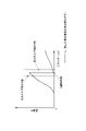
- 4 is a graph showing the X-ray absorption edge of a foreign object to be detected and the energy of spectrally separated X-rays in the same embodiment.
- It is a functional block diagram of the signal processing device in the same embodiment.
- 7 is a graph showing the X-ray absorption edges of the first foreign matter and the second foreign matter and the energy of the dispersed X-rays in the modified embodiment.
- the transmission X-ray inspection apparatus 100 of the present embodiment includes an X-ray source 2 that emits primary X-rays, and an optical element that disperses and focuses the primary X-rays toward a sample W. 3 , a transmitted X-ray detector 4 that detects transmitted X-rays that have passed through the sample W, and a signal processing device 5 that processes detection signals from the transmitted X-ray detector 4 .
- the transmission X-ray inspection apparatus 100 of this embodiment has a transport mechanism 6 that transports the sample W to be inspected in a predetermined direction (in FIG. 2, the horizontal direction of the paper surface, here the X direction).
- the optical element 3 and the transmission X-ray detector 4 are arranged to sandwich the sample W transported by the transport mechanism 6 from above and below.
- the transmission X-ray inspection apparatus 100 of the present embodiment can inspect the sample W for foreign substances while the sample W is transported by the transport mechanism 6 .
- the transmission X-ray inspection apparatus 100 can be an in-line system incorporated in, for example, a film coating device 7 that coats a base material with a film material.
- the sample W of this embodiment is, for example, a positive electrode material for a lithium ion battery, and the foreign matter S to be detected is copper (energy of K absorption edge is 8.98 keV).
- the X-ray source 2 emits primary X-rays (polychromatic X-rays) containing a plurality of mutually different energy ranges (wavelength ranges).
- the X-ray source 2 is an X-ray tube that generates continuous X-rays and characteristic X-rays by colliding electrons generated by heating a filament against a target metal such as tungsten or molybdenum.
- a target metal such as tungsten or molybdenum.
- the target metal in this embodiment is tungsten.
- the optical element 3 focuses the primary X-rays toward the sample W while dispersing the primary X-rays into X-rays in one energy range (one wavelength range).
- one energy region (one wavelength region) is set based on the transmittance of the foreign matter S to be detected, particularly the X-ray absorption edge (here, the K absorption edge of copper).
- the optical element 3 is a curved spectroscopic element that disperses (monochromatic) X-rays of one energy range and converges them into a line.
- the longitudinal direction of the X-rays linearly condensed by the optical element 3 a is the direction (Y direction) perpendicular to the transport direction of the transport mechanism 6 .
- the primary X-rays incident with a spread are Bragg-reflected by the curved crystal surface, condensed at a predetermined position (here, the upper surface of the sample W), and are focused in a predetermined energy range. Only X-rays can be extracted.
- the curved spectroscopic element examples include those used as spectroscopic crystals such as silicon, graphite, and lithium fluoride.
- the X-ray wavelength to be focused is changed by changing the degree of curvature (size of Rowland circle) of the spectroscopy crystal.
- the wavelength to be dispersed can be changed by changing the curvature of the analyzing crystal (the size of the Rowland circle) and/or the material of the analyzing crystal to change the X-ray wavelength to be focused.
- the optical element 3 of this embodiment disperses and converges L ⁇ (high energy; 9.67 to 9.96 keV) and L ⁇ (low energy; 8.40 keV) of fluorescent X-rays of tungsten.
- this embodiment has a plurality of types (here, two types) of optical elements 3a and 3b that disperse X-rays in different energy ranges.
- One of the two types of optical element 3a focuses light on the sample W while dispersing the X-rays into high-energy X-rays.
- the optical element 3b which is the other of the two types, focuses the X-rays on the sample W while dispersing the X-rays into low-energy region X-rays.
- the X-rays dispersed by one optical element 3a are X-rays in an energy range higher than the X-ray absorption edge of the foreign matter S to be detected in the sample W.
- the X-rays dispersed by the other optical element 3b are X-rays in an energy range lower than the X-ray absorption edge of the foreign matter S to be detected in the sample W.
- the transmitted X-ray detector 4 detects transmitted X-rays that have passed through the sample W, and as shown in FIGS. It is configured using devices 4a and 4b.
- the transmission X-ray detectors 4a and 4b are provided corresponding to the X-rays that are linearly condensed. That is, the longitudinal direction of the transmission X-ray detectors 4 a and 4 b is the direction (Y direction) perpendicular to the transport direction of the transport mechanism 6 . Furthermore, the pixel width of the transmission X-ray detectors 4a and 4b is substantially the same as the width of the linearly focused X-rays.
- the transmission X-ray detector 4 of this embodiment includes a plurality of (here, two) transmission X-ray detectors 4a and 4b for generating a plurality of transmission X-ray images corresponding to X-rays in mutually different energy ranges.
- One transmitted X-ray detector 4a is a line sensor provided corresponding to one optical element 3a, and detects transmitted X-rays from a sample W irradiated with X-rays in a high energy range.
- the other transmitted X-ray detector 4b is a line sensor provided corresponding to the other optical element 3b, and detects transmitted X-rays from the sample W irradiated with X-rays in the low energy range.
- Each line sensor has a linear scintillator and an X-ray filter provided in front of the scintillator on the X-ray incident side.
- the X-ray filter transmits X-rays to be detected and blocks other X-rays that may cause disturbance.
- the line sensor may be configured using a semiconductor radiation detector (SDD), a photomultiplier tube, or the like.
- the signal processing device 5 processes the detection signal from the transmission X-ray detector 4 to generate a transmission X-ray image, and also detects foreign matter from the transmission X-ray image.
- the signal processing device is a computer having a CPU, a memory, an input/output interface, a display 50, input means, etc. As shown in FIG. It has functions such as the display control unit 5d.
- the image generator 5a acquires detection signals from the plurality of transmission X-ray detectors 4a and 4b and generates a plurality of transmission X-ray images.
- a detection signal from one transmission X-ray detector 4a is used to generate a transmission X-ray image in a high energy region
- a detection signal from the other transmission X-ray detector 4b is used to generate a low energy region transmission X-ray image.
- a transmission X-ray image of the energy range is generated.
- the transmitted X-ray image generated by the image generation unit 5a is transmitted to the image processing unit 5b and also to the display control unit 5d.
- the image processing unit 5b detects foreign matter in the sample W by performing differential processing using the transmission X-ray image in the high energy region and the transmission X-ray image in the low energy region generated by the image generation unit 5a.
- the image processing unit 5b generates a difference image between the transmission X-ray image in the high energy region and the transmission X-ray image in the low energy region, increases the contrast of the transmission X-ray image, and removes the foreign matter S. Make it easier to extract.
- the difference image generated by the image processing unit 5b is transmitted to the foreign object detection unit 5c and also to the display control unit 5d.
- the foreign matter detection unit 5c detects the foreign matter S from the difference image generated by the difference processing of the image processing unit 5b. For example, the foreign matter detection unit 5c obtains the size of the foreign matter from the difference image, and detects the foreign matter if the size of the foreign matter is 20 ⁇ m or more in terms of area-equivalent diameter.
- Foreign matter information indicating the foreign matter detected by the foreign matter detection unit 5c is sent to the display control unit 5d.
- the foreign object information is image data in which a foreign object is detected, and the image data is also stored in the memory of the signal processing device 5 . Further, the foreign object detection unit 5c can also transmit image data together with error information indicating that a foreign object has been detected to a server (upper control device) or the like in the control room.
- the display control unit 5d causes the display 50 to display the foreign matter S detected by the foreign matter detection unit 5c. Specifically, the display control unit 5d causes the display 50 to display the difference image generated by the image processing unit 5b and the detected foreign matter in an overlapping manner. Here, the display control unit 5d can display the detected foreign matter in a manner that is easy for the user to visually recognize, such as displaying the detected foreign matter in a different color.
- the display control unit 5d can also display on the display 50 the X-ray transmission image of each energy region generated by the image generation unit 5a or the differential image generated by the image processing unit 5b. Further, the display control unit 5d can cause the display 50 to display the X-ray transmission image of each energy region generated by the image generation unit 5a and the detected foreign matter in a superimposed manner.
- X-rays including a plurality of energy ranges different from each other are separated into X-rays of one energy range and focused toward the sample W.
- the intensity of X-rays in one energy region irradiated to the sample W can be improved, and the contrast of transmitted X-rays can be increased.
- the detection sensitivity of the foreign matter S in the sample W can be improved in the transmission X-ray inspection apparatus 100 .
- the time required to inspect each sample W for foreign matter can be shortened.
- the intensity of X-rays in one energy range with which the transported sample W is irradiated can be improved.
- the integrated dose of the transmitted X-ray detector 4 can be increased without lengthening the counting time, and the contrast of the transmitted X-rays can be increased even when transported at a higher speed than before. .
- one type of foreign matter is detected, but two or more types of foreign matter may be detected.
- the optical element 3 is exposed to the first X-ray (see FIG. 5) in a lower energy range than the X-ray absorption edge of the first foreign substance.
- a first optical element to disperse the spectrum into a second X-ray in an energy range higher than the X-ray absorption edge of the first foreign matter and lower in energy than the X-ray absorption edge of the second foreign matter and a third optical element that disperses into third X-rays (see FIG.
- the first to third optical elements are curved spectroscopic elements as in the above embodiment.
- the transmission X-ray detector 4 has three transmission X-ray detectors corresponding to these three optical elements.
- the image processing unit 5b irradiates a first transmission X-ray image obtained by irradiating the first X-ray, a second transmission X-ray image obtained by irradiating the second X-ray, and a third X-ray. Difference processing is performed using the third transmission X-ray image obtained by the first foreign matter and the second foreign matter is detected. Specifically, the first foreign matter is detected by difference processing between the second X-ray image and the first X-ray image, and the second foreign matter is detected by difference processing between the third X-ray image and the second X-ray image.
- the display control unit 5d may separately display the detected first foreign matter and the second foreign matter, or may color-code the first foreign matter and the second foreign matter in one image with different colors. may Note that the first foreign matter may be detected by difference processing between the third X-ray image and the first X-ray image.
- the signal processing device 5 may further include a correction unit that corrects differences in X-ray intensity with which the sample W is irradiated from each of the plurality of optical elements 3 .
- This correction unit corrects the parameters used when generating the transmission X image in the image generation unit 5a based on the optical arrangement of the X-ray source 2, the transmission X-ray detection unit 4, and the plurality of optical elements 3. It can be.
- the correcting section may correct a plurality of transmitted X-ray images based on the optical arrangement of the X-ray source 2 and the transmitted X-ray detection section 4 and the plurality of optical elements 3 .
- the X-rays from one X-ray source 2 are separated into X-rays of different energy ranges by a plurality of optical elements 3. Also good.
- an X-ray source 2 may be provided for each of the plurality of optical elements 3 .
- the configuration has a plurality of optical elements and a plurality of transmission X-ray detectors, but the configuration may have one optical element and one transmission X-ray detector.
- the optical element disperses and converges X-rays with energy higher than the K absorption edge of the foreign matter.
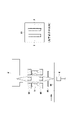
- the configuration shown in FIG. 6 may be used as a configuration for dispersing the X-rays from the X-ray source 2 into X-rays of one energy range and irradiating the sample W with the X-rays.
- the configuration shown in FIG. 6 places two identical optical elements 3 opposite each other.
- the two optical elements 3 are curved spectroscopic elements that disperse (monochromatic) X-rays in the same energy range and converge them linearly.
- the two optical elements 3 are arranged so that the X-rays condensed in a line by each optical element 3 coincide with each other on the sample W. As shown in FIG.
- a first collimator 81 is provided between the X-ray source and the optical element 3 to remove X-rays that do not enter the optical element 3. Between the optical element 3 and the sample W, A second collimator 82 is provided to filter out X-rays other than those in the desired energy range. A third collimator 83 for removing unnecessary X-rays may be provided between the second collimator and the sample W, if necessary. With the configuration of the optical system as shown in FIG. 6, the intensity of X-rays with which the sample W is irradiated can be improved.
- the integrated dose of the transmitted X-ray detector can be increased without lengthening the counting time, and the contrast of the transmitted X-rays can be increased even if the wafer is transported at a higher speed than before. As a result, it is possible to improve the precision and speed of foreign matter inspection of a sample.
- a configuration that includes a notification unit that notifies the user by, for example, issuing an error when the foreign object detection unit detects a foreign object.
- the specimen W conveyed by the conveying mechanism 6 is inspected for foreign matter, but this is a stand-alone type in which the specimen is placed on a fixed inspection table and inspected for foreign matter. can be
- Reference numeral 100 Transmission X-ray inspection apparatus W...Sample 2...X-ray source 3 (3a, 3b).
- Optical element 4 ...Transmission X-ray detectors 4a, 4b...Transmission X-ray Detector 5 Signal processing device 51 Image processing unit 52 Display control unit
Landscapes
- Health & Medical Sciences (AREA)
- Physics & Mathematics (AREA)
- Life Sciences & Earth Sciences (AREA)
- Chemical & Material Sciences (AREA)
- Analytical Chemistry (AREA)
- Biochemistry (AREA)
- General Health & Medical Sciences (AREA)
- General Physics & Mathematics (AREA)
- Immunology (AREA)
- Pathology (AREA)
- Toxicology (AREA)
- Analysing Materials By The Use Of Radiation (AREA)
Priority Applications (3)
| Application Number | Priority Date | Filing Date | Title |
|---|---|---|---|
| JP2023531997A JP7846111B2 (ja) | 2021-06-30 | 2022-06-28 | 透過x線検査装置、及び透過x線検査方法 |
| DE112022003317.7T DE112022003317T5 (de) | 2021-06-30 | 2022-06-28 | Transmissions-röntgenprüfvorrichtung und transmissions-röntgenprüfverfahren |
| CN202280044285.1A CN117546011A (zh) | 2021-06-30 | 2022-06-28 | 透射x射线检查装置和透射x射线检查方法 |
Applications Claiming Priority (2)
| Application Number | Priority Date | Filing Date | Title |
|---|---|---|---|
| JP2021108333 | 2021-06-30 | ||
| JP2021-108333 | 2021-06-30 |
Publications (1)
| Publication Number | Publication Date |
|---|---|
| WO2023277039A1 true WO2023277039A1 (ja) | 2023-01-05 |
Family
ID=84691447
Family Applications (1)
| Application Number | Title | Priority Date | Filing Date |
|---|---|---|---|
| PCT/JP2022/025838 Ceased WO2023277039A1 (ja) | 2021-06-30 | 2022-06-28 | 透過x線検査装置、及び透過x線検査方法 |
Country Status (4)
| Country | Link |
|---|---|
| JP (1) | JP7846111B2 (https=) |
| CN (1) | CN117546011A (https=) |
| DE (1) | DE112022003317T5 (https=) |
| WO (1) | WO2023277039A1 (https=) |
Cited By (1)
| Publication number | Priority date | Publication date | Assignee | Title |
|---|---|---|---|---|
| JP2025006215A (ja) * | 2023-06-29 | 2025-01-17 | アンリツ株式会社 | X線検査装置および物品検査システムならびにx線画像形成装置 |
Citations (6)
| Publication number | Priority date | Publication date | Assignee | Title |
|---|---|---|---|---|
| US5596620A (en) * | 1993-04-30 | 1997-01-21 | The University Of Connecticut | X-ray based extensometry device for radiography |
| JPH10318943A (ja) * | 1997-05-20 | 1998-12-04 | Shimadzu Corp | 異物検査装置 |
| JP2009178517A (ja) * | 2008-02-01 | 2009-08-13 | Ge Medical Systems Global Technology Co Llc | 画像処理装置及びx線ct装置 |
| KR20120013724A (ko) * | 2010-08-06 | 2012-02-15 | 라드텍주식회사 | 이중 에너지 x-선 흡광분석을 이용한 x-선 영상장치 |
| JP2018031643A (ja) * | 2016-08-24 | 2018-03-01 | 株式会社日立ハイテクサイエンス | X線透過検査装置 |
| JP2018130336A (ja) * | 2017-02-15 | 2018-08-23 | キヤノン株式会社 | 放射線撮影装置、放射線撮影システム、放射線撮影方法、及びプログラム |
Family Cites Families (2)
| Publication number | Priority date | Publication date | Assignee | Title |
|---|---|---|---|---|
| US8311184B2 (en) | 2010-08-30 | 2012-11-13 | General Electric Company | Fan-shaped X-ray beam imaging systems employing graded multilayer optic devices |
| JP6663374B2 (ja) | 2017-02-28 | 2020-03-11 | アンリツインフィビス株式会社 | X線検査装置 |
-
2022
- 2022-06-28 WO PCT/JP2022/025838 patent/WO2023277039A1/ja not_active Ceased
- 2022-06-28 DE DE112022003317.7T patent/DE112022003317T5/de active Pending
- 2022-06-28 JP JP2023531997A patent/JP7846111B2/ja active Active
- 2022-06-28 CN CN202280044285.1A patent/CN117546011A/zh active Pending
Patent Citations (6)
| Publication number | Priority date | Publication date | Assignee | Title |
|---|---|---|---|---|
| US5596620A (en) * | 1993-04-30 | 1997-01-21 | The University Of Connecticut | X-ray based extensometry device for radiography |
| JPH10318943A (ja) * | 1997-05-20 | 1998-12-04 | Shimadzu Corp | 異物検査装置 |
| JP2009178517A (ja) * | 2008-02-01 | 2009-08-13 | Ge Medical Systems Global Technology Co Llc | 画像処理装置及びx線ct装置 |
| KR20120013724A (ko) * | 2010-08-06 | 2012-02-15 | 라드텍주식회사 | 이중 에너지 x-선 흡광분석을 이용한 x-선 영상장치 |
| JP2018031643A (ja) * | 2016-08-24 | 2018-03-01 | 株式会社日立ハイテクサイエンス | X線透過検査装置 |
| JP2018130336A (ja) * | 2017-02-15 | 2018-08-23 | キヤノン株式会社 | 放射線撮影装置、放射線撮影システム、放射線撮影方法、及びプログラム |
Cited By (1)
| Publication number | Priority date | Publication date | Assignee | Title |
|---|---|---|---|---|
| JP2025006215A (ja) * | 2023-06-29 | 2025-01-17 | アンリツ株式会社 | X線検査装置および物品検査システムならびにx線画像形成装置 |
Also Published As
| Publication number | Publication date |
|---|---|
| JP7846111B2 (ja) | 2026-04-14 |
| DE112022003317T5 (de) | 2024-04-11 |
| JPWO2023277039A1 (https=) | 2023-01-05 |
| CN117546011A (zh) | 2024-02-09 |
Similar Documents
| Publication | Publication Date | Title |
|---|---|---|
| US20130195244A1 (en) | X-Ray Inspector | |
| US8068583B2 (en) | X-ray analysis apparatus and X-ray analysis method | |
| JP6397690B2 (ja) | X線透過検査装置及び異物検出方法 | |
| US9164045B2 (en) | Phase imaging | |
| JP5555048B2 (ja) | X線検査装置 | |
| JP2012513023A5 (https=) | ||
| CN104487868B (zh) | 放射线图像取得装置 | |
| JP2002365368A (ja) | X線検出器及び該検出器を用いたx線異物検出装置 | |
| CN109791116B (zh) | 波长色散型荧光x射线分析装置 | |
| WO2017110508A1 (ja) | 放射線検出装置、放射線検査システム、及び、放射線検出装置の調整方法 | |
| TWI765866B (zh) | 用於x射線檢測之裝置和系統、貨物掃描或非侵入式檢查系統、全身掃描器系統、x射線電腦斷層攝影系統、電子顯微鏡及適合於相襯x射線成像的系統 | |
| WO2023277039A1 (ja) | 透過x線検査装置、及び透過x線検査方法 | |
| JP2011043474A (ja) | X線検出器およびx線検査装置 | |
| JP7060446B2 (ja) | X線ラインセンサ及びそれを用いたx線異物検出装置 | |
| JP2014222191A (ja) | 蛍光x線分析装置 | |
| US11119059B2 (en) | Semiconductor defect inspection apparatus and semiconductor defect inspection method | |
| JP4853964B2 (ja) | X線検査装置用のx線センサ | |
| JP6506629B2 (ja) | X線受光装置およびこれを備えたx線検査装置 | |
| Eckel et al. | Radiographic film system classification and noise characterisation by a camera-based digitisation procedure | |
| JPWO2023277039A5 (https=) | ||
| JP2011099725A (ja) | 物品検査装置 | |
| Schumacher et al. | Influencing parameters on image quality using photon counting detectors for laminography | |
| US10866331B2 (en) | X-ray inspection apparatus | |
| Dutra et al. | Characterization of Agfa Structurix series D4 and D3sc x-ray films in the 0.7–4.6 keV energy range | |
| JP2000055842A (ja) | X線撮像分析方法および装置 |
Legal Events
| Date | Code | Title | Description |
|---|---|---|---|
| 121 | Ep: the epo has been informed by wipo that ep was designated in this application |
Ref document number: 22833185 Country of ref document: EP Kind code of ref document: A1 |
|
| WWE | Wipo information: entry into national phase |
Ref document number: 2023531997 Country of ref document: JP |
|
| WWE | Wipo information: entry into national phase |
Ref document number: 202280044285.1 Country of ref document: CN |
|
| WWE | Wipo information: entry into national phase |
Ref document number: 112022003317 Country of ref document: DE |
|
| 122 | Ep: pct application non-entry in european phase |
Ref document number: 22833185 Country of ref document: EP Kind code of ref document: A1 |