WO2023277039A1 - 透過x線検査装置、及び透過x線検査方法 - Google Patents
透過x線検査装置、及び透過x線検査方法 Download PDFInfo
- Publication number
- WO2023277039A1 WO2023277039A1 PCT/JP2022/025838 JP2022025838W WO2023277039A1 WO 2023277039 A1 WO2023277039 A1 WO 2023277039A1 JP 2022025838 W JP2022025838 W JP 2022025838W WO 2023277039 A1 WO2023277039 A1 WO 2023277039A1
- Authority
- WO
- WIPO (PCT)
- Prior art keywords
- ray
- rays
- transmission
- sample
- foreign matter
- Prior art date
Links
- 230000005540 biological transmission Effects 0.000 title claims abstract description 106
- 238000000034 method Methods 0.000 title claims description 7
- 230000003287 optical effect Effects 0.000 claims abstract description 77
- 238000001514 detection method Methods 0.000 claims abstract description 39
- 238000007689 inspection Methods 0.000 claims description 46
- 238000010521 absorption reaction Methods 0.000 claims description 32
- 230000007723 transport mechanism Effects 0.000 claims description 13
- 239000000126 substance Substances 0.000 claims description 10
- 230000001678 irradiating effect Effects 0.000 claims description 8
- 230000032258 transport Effects 0.000 claims description 5
- 230000008569 process Effects 0.000 claims description 3
- 230000035945 sensitivity Effects 0.000 abstract description 13
- 239000013078 crystal Substances 0.000 description 6
- 239000000463 material Substances 0.000 description 4
- 229910052721 tungsten Inorganic materials 0.000 description 4
- RYGMFSIKBFXOCR-UHFFFAOYSA-N Copper Chemical group [Cu] RYGMFSIKBFXOCR-UHFFFAOYSA-N 0.000 description 3
- 229910052802 copper Inorganic materials 0.000 description 3
- 239000010949 copper Substances 0.000 description 3
- WFKWXMTUELFFGS-UHFFFAOYSA-N tungsten Chemical compound [W] WFKWXMTUELFFGS-UHFFFAOYSA-N 0.000 description 3
- 239000010937 tungsten Substances 0.000 description 3
- PQXKHYXIUOZZFA-UHFFFAOYSA-M lithium fluoride Chemical compound [Li+].[F-] PQXKHYXIUOZZFA-UHFFFAOYSA-M 0.000 description 2
- 229910052751 metal Inorganic materials 0.000 description 2
- 239000002184 metal Substances 0.000 description 2
- 238000004611 spectroscopical analysis Methods 0.000 description 2
- OKTJSMMVPCPJKN-UHFFFAOYSA-N Carbon Chemical compound [C] OKTJSMMVPCPJKN-UHFFFAOYSA-N 0.000 description 1
- HBBGRARXTFLTSG-UHFFFAOYSA-N Lithium ion Chemical compound [Li+] HBBGRARXTFLTSG-UHFFFAOYSA-N 0.000 description 1
- ZOKXTWBITQBERF-UHFFFAOYSA-N Molybdenum Chemical compound [Mo] ZOKXTWBITQBERF-UHFFFAOYSA-N 0.000 description 1
- XUIMIQQOPSSXEZ-UHFFFAOYSA-N Silicon Chemical compound [Si] XUIMIQQOPSSXEZ-UHFFFAOYSA-N 0.000 description 1
- 230000008859 change Effects 0.000 description 1
- 239000003086 colorant Substances 0.000 description 1
- 238000010586 diagram Methods 0.000 description 1
- 230000000694 effects Effects 0.000 description 1
- 239000007888 film coating Substances 0.000 description 1
- 238000009501 film coating Methods 0.000 description 1
- 230000006870 function Effects 0.000 description 1
- 229910002804 graphite Inorganic materials 0.000 description 1
- 239000010439 graphite Substances 0.000 description 1
- 238000010438 heat treatment Methods 0.000 description 1
- 229910001416 lithium ion Inorganic materials 0.000 description 1
- 230000007246 mechanism Effects 0.000 description 1
- 238000012986 modification Methods 0.000 description 1
- 230000004048 modification Effects 0.000 description 1
- 229910052750 molybdenum Inorganic materials 0.000 description 1
- 239000011733 molybdenum Substances 0.000 description 1
- 239000007774 positive electrode material Substances 0.000 description 1
- 230000005855 radiation Effects 0.000 description 1
- 239000004065 semiconductor Substances 0.000 description 1
- 229910052710 silicon Inorganic materials 0.000 description 1
- 239000010703 silicon Substances 0.000 description 1
- 238000001228 spectrum Methods 0.000 description 1
- 230000007480 spreading Effects 0.000 description 1
- 238000002834 transmittance Methods 0.000 description 1
Images


Classifications
-
- G—PHYSICS
- G01—MEASURING; TESTING
- G01N—INVESTIGATING OR ANALYSING MATERIALS BY DETERMINING THEIR CHEMICAL OR PHYSICAL PROPERTIES
- G01N23/00—Investigating or analysing materials by the use of wave or particle radiation, e.g. X-rays or neutrons, not covered by groups G01N3/00 – G01N17/00, G01N21/00 or G01N22/00
- G01N23/02—Investigating or analysing materials by the use of wave or particle radiation, e.g. X-rays or neutrons, not covered by groups G01N3/00 – G01N17/00, G01N21/00 or G01N22/00 by transmitting the radiation through the material
- G01N23/06—Investigating or analysing materials by the use of wave or particle radiation, e.g. X-rays or neutrons, not covered by groups G01N3/00 – G01N17/00, G01N21/00 or G01N22/00 by transmitting the radiation through the material and measuring the absorption
- G01N23/083—Investigating or analysing materials by the use of wave or particle radiation, e.g. X-rays or neutrons, not covered by groups G01N3/00 – G01N17/00, G01N21/00 or G01N22/00 by transmitting the radiation through the material and measuring the absorption the radiation being X-rays
- G01N23/087—Investigating or analysing materials by the use of wave or particle radiation, e.g. X-rays or neutrons, not covered by groups G01N3/00 – G01N17/00, G01N21/00 or G01N22/00 by transmitting the radiation through the material and measuring the absorption the radiation being X-rays using polyenergetic X-rays
-
- G—PHYSICS
- G01—MEASURING; TESTING
- G01N—INVESTIGATING OR ANALYSING MATERIALS BY DETERMINING THEIR CHEMICAL OR PHYSICAL PROPERTIES
- G01N23/00—Investigating or analysing materials by the use of wave or particle radiation, e.g. X-rays or neutrons, not covered by groups G01N3/00 – G01N17/00, G01N21/00 or G01N22/00
- G01N23/02—Investigating or analysing materials by the use of wave or particle radiation, e.g. X-rays or neutrons, not covered by groups G01N3/00 – G01N17/00, G01N21/00 or G01N22/00 by transmitting the radiation through the material
- G01N23/04—Investigating or analysing materials by the use of wave or particle radiation, e.g. X-rays or neutrons, not covered by groups G01N3/00 – G01N17/00, G01N21/00 or G01N22/00 by transmitting the radiation through the material and forming images of the material
-
- G—PHYSICS
- G01—MEASURING; TESTING
- G01N—INVESTIGATING OR ANALYSING MATERIALS BY DETERMINING THEIR CHEMICAL OR PHYSICAL PROPERTIES
- G01N23/00—Investigating or analysing materials by the use of wave or particle radiation, e.g. X-rays or neutrons, not covered by groups G01N3/00 – G01N17/00, G01N21/00 or G01N22/00
- G01N23/02—Investigating or analysing materials by the use of wave or particle radiation, e.g. X-rays or neutrons, not covered by groups G01N3/00 – G01N17/00, G01N21/00 or G01N22/00 by transmitting the radiation through the material
- G01N23/06—Investigating or analysing materials by the use of wave or particle radiation, e.g. X-rays or neutrons, not covered by groups G01N3/00 – G01N17/00, G01N21/00 or G01N22/00 by transmitting the radiation through the material and measuring the absorption
- G01N23/18—Investigating the presence of flaws defects or foreign matter
-
- G—PHYSICS
- G01—MEASURING; TESTING
- G01N—INVESTIGATING OR ANALYSING MATERIALS BY DETERMINING THEIR CHEMICAL OR PHYSICAL PROPERTIES
- G01N2223/00—Investigating materials by wave or particle radiation
- G01N2223/40—Imaging
- G01N2223/426—Imaging image comparing, unknown with known substance
-
- G—PHYSICS
- G01—MEASURING; TESTING
- G01N—INVESTIGATING OR ANALYSING MATERIALS BY DETERMINING THEIR CHEMICAL OR PHYSICAL PROPERTIES
- G01N2223/00—Investigating materials by wave or particle radiation
- G01N2223/60—Specific applications or type of materials
- G01N2223/652—Specific applications or type of materials impurities, foreign matter, trace amounts
Definitions
- the present invention relates to a transmission X-ray inspection apparatus and a transmission X-ray inspection method.
- Patent Document 1 Conventionally, as a system for inspecting foreign matter in a sample, there is a system using a transmission X-ray inspection device, as shown in Patent Document 1.
- This transmission X-ray inspection apparatus irradiates a sample with X-rays from an X-ray generator, detects the transmitted X-rays that have passed through the sample, and inspects foreign matter.
- the intensity of the X-rays irradiated onto the sample is weak, and as a result, the intensity of the transmitted X-rays that pass through the sample is also weak. Therefore, the detection sensitivity of the transmission X-ray detector is lowered.
- the present invention has been made in view of the problems described above, and its main object is to improve the detection sensitivity of foreign matter in a sample in a transmission X-ray inspection apparatus.
- a transmission X-ray inspection apparatus includes an X-ray source that emits X-rays containing a plurality of energy ranges different from each other, and an X-ray source that splits the X-rays into X-rays of one energy range and collects them toward a sample. It is characterized by comprising an optical element that emits light, and a transmitted X-ray detector that detects transmitted X-rays that have passed through the sample.
- X-rays containing a plurality of mutually different energy ranges are dispersed into X-rays in one energy range and focused toward the sample.
- the intensity of lines can be improved, and the contrast of transmitted X-rays can be increased.
- the foreign matter inspection time for each sample can be shortened.
- foreign matter in the sample includes foreign matter adhering to the surface of the sample and foreign matter contained inside the sample.
- the optical element is desirably a curved spectroscopic element that linearly collects the X-rays of the one energy range.
- the transmitted X-ray detector is a line sensor provided corresponding to the linearly focused X-rays.
- the pixel width of the line sensor is substantially the same as the width of the X-rays condensed into the line. is desirable.
- the transmission X-ray inspection apparatus of the present invention is used together with a transport mechanism for transporting the sample, and the optical element and the transmission X-ray detection unit sandwich the sample transported by the transport mechanism. should be placed.
- the longitudinal direction of the line-condensed X-rays and the longitudinal direction of the line sensor be perpendicular to the transport direction of the transport mechanism.
- the integrated dose of the transmitted X-ray detector can be increased without lengthening the counting time, and the contrast of the transmitted X-rays can be increased even if the wafer is transported at a higher speed than before. As a result, it is possible to speed up the foreign matter inspection of the sample.
- the optical element should disperse X-rays in an energy range higher than the X-ray absorption edge of the foreign matter to be detected in the sample.
- the X-ray absorption edge of the foreign matter is a concept including, for example, the K absorption edge, the L1 absorption edge, the L2 absorption edge, or the L3 absorption edge. is selected.
- the K absorption edge can be selected.
- the integrated dose of the transmitted X-ray detector can be increased without lengthening the counting time, and the contrast of the transmitted X-rays can be increased even when transported at a higher speed than before. can be done. As a result, it is possible to improve the precision and speed of foreign matter inspection of a sample.
- the transmission X-ray inspection apparatus of the present invention has a plurality of types of optical elements, and the plurality of types of It is desirable that the optical elements disperse X-rays in different energy ranges.
- two types of the optical element are provided, and one of the two types of the optical element serves as a detection target in the sample. It disperses X-rays in an energy range higher than the X-ray absorption edge of the foreign matter, and the other optical element of the two types disperses X-rays in an energy range lower than the X-ray absorption edge. is desirable.
- the plurality of types of optical elements disperse X-rays from one X-ray source into X-rays of different energy ranges.
- the transmission X-ray detection section may It is desirable to have multiple transmission x-ray detectors for generating multiple transmission x-ray images corresponding to respective x-rays.
- the transmission X-ray inspection apparatus of the present invention further includes an image processing unit for processing transmission X-ray images generated using each of the plurality of transmission X-ray detectors, It is preferable that the image processing section performs differential processing using a plurality of transmitted X-ray images corresponding to the X-rays in the energy ranges different from each other, and detects foreign matter in the sample.
- the transmission X-ray inspection apparatus of the present invention further includes a display control unit that displays the transmission X-ray image on a display, and the display control unit performs the image processing. It is desirable that the foreign matter detected by the unit is displayed in a different color.
- the optical element disperses the first X-rays in an energy region lower than the X-ray absorption edge of the first foreign substance.
- a first optical element and a second optical element that disperses into second X-rays in an energy range higher than the X-ray absorption edge of the first foreign matter and lower in energy than the X-ray absorption edge of the second foreign matter.
- a third optical element that disperses into third X-rays in an energy range higher than the X-ray absorption edge of the second foreign matter
- the image processing unit comprises a first X-ray obtained by irradiating the first X-rays.
- Differential processing is performed using the transmission X-ray image, the second transmission X-ray image obtained by irradiating the second X-ray, and the third transmission X-ray image obtained by irradiating the third X-ray.
- the first foreign object and the second foreign object are preferably detected.
- the transmission X-ray inspection apparatus of the present invention further include a correction unit that corrects differences in X-ray intensities with which the sample is irradiated from each of the plurality of types of optical elements.
- X-rays containing a plurality of mutually different energy ranges emitted from an X-ray source are dispersed into X-rays of one energy range by an optical element and directed toward a sample. It is characterized in that the transmitted X-rays that are condensed and transmitted through the sample are detected by a transmitted X-ray detector.
- FIG. 1 is a perspective view schematically showing the overall configuration of a transmission X-ray inspection apparatus according to one embodiment of the present invention
- FIG. It is a side view which shows typically the whole structure of the transmission X-ray inspection apparatus in the same embodiment.
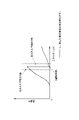
- 4 is a graph showing the X-ray absorption edge of a foreign object to be detected and the energy of spectrally separated X-rays in the same embodiment.
- It is a functional block diagram of the signal processing device in the same embodiment.
- 7 is a graph showing the X-ray absorption edges of the first foreign matter and the second foreign matter and the energy of the dispersed X-rays in the modified embodiment.
- the transmission X-ray inspection apparatus 100 of the present embodiment includes an X-ray source 2 that emits primary X-rays, and an optical element that disperses and focuses the primary X-rays toward a sample W. 3 , a transmitted X-ray detector 4 that detects transmitted X-rays that have passed through the sample W, and a signal processing device 5 that processes detection signals from the transmitted X-ray detector 4 .
- the transmission X-ray inspection apparatus 100 of this embodiment has a transport mechanism 6 that transports the sample W to be inspected in a predetermined direction (in FIG. 2, the horizontal direction of the paper surface, here the X direction).
- the optical element 3 and the transmission X-ray detector 4 are arranged to sandwich the sample W transported by the transport mechanism 6 from above and below.
- the transmission X-ray inspection apparatus 100 of the present embodiment can inspect the sample W for foreign substances while the sample W is transported by the transport mechanism 6 .
- the transmission X-ray inspection apparatus 100 can be an in-line system incorporated in, for example, a film coating device 7 that coats a base material with a film material.
- the sample W of this embodiment is, for example, a positive electrode material for a lithium ion battery, and the foreign matter S to be detected is copper (energy of K absorption edge is 8.98 keV).
- the X-ray source 2 emits primary X-rays (polychromatic X-rays) containing a plurality of mutually different energy ranges (wavelength ranges).
- the X-ray source 2 is an X-ray tube that generates continuous X-rays and characteristic X-rays by colliding electrons generated by heating a filament against a target metal such as tungsten or molybdenum.
- a target metal such as tungsten or molybdenum.
- the target metal in this embodiment is tungsten.
- the optical element 3 focuses the primary X-rays toward the sample W while dispersing the primary X-rays into X-rays in one energy range (one wavelength range).
- one energy region (one wavelength region) is set based on the transmittance of the foreign matter S to be detected, particularly the X-ray absorption edge (here, the K absorption edge of copper).
- the optical element 3 is a curved spectroscopic element that disperses (monochromatic) X-rays of one energy range and converges them into a line.
- the longitudinal direction of the X-rays linearly condensed by the optical element 3 a is the direction (Y direction) perpendicular to the transport direction of the transport mechanism 6 .
- the primary X-rays incident with a spread are Bragg-reflected by the curved crystal surface, condensed at a predetermined position (here, the upper surface of the sample W), and are focused in a predetermined energy range. Only X-rays can be extracted.
- the curved spectroscopic element examples include those used as spectroscopic crystals such as silicon, graphite, and lithium fluoride.
- the X-ray wavelength to be focused is changed by changing the degree of curvature (size of Rowland circle) of the spectroscopy crystal.
- the wavelength to be dispersed can be changed by changing the curvature of the analyzing crystal (the size of the Rowland circle) and/or the material of the analyzing crystal to change the X-ray wavelength to be focused.
- the optical element 3 of this embodiment disperses and converges L ⁇ (high energy; 9.67 to 9.96 keV) and L ⁇ (low energy; 8.40 keV) of fluorescent X-rays of tungsten.
- this embodiment has a plurality of types (here, two types) of optical elements 3a and 3b that disperse X-rays in different energy ranges.
- One of the two types of optical element 3a focuses light on the sample W while dispersing the X-rays into high-energy X-rays.
- the optical element 3b which is the other of the two types, focuses the X-rays on the sample W while dispersing the X-rays into low-energy region X-rays.
- the X-rays dispersed by one optical element 3a are X-rays in an energy range higher than the X-ray absorption edge of the foreign matter S to be detected in the sample W.
- the X-rays dispersed by the other optical element 3b are X-rays in an energy range lower than the X-ray absorption edge of the foreign matter S to be detected in the sample W.
- the transmitted X-ray detector 4 detects transmitted X-rays that have passed through the sample W, and as shown in FIGS. It is configured using devices 4a and 4b.
- the transmission X-ray detectors 4a and 4b are provided corresponding to the X-rays that are linearly condensed. That is, the longitudinal direction of the transmission X-ray detectors 4 a and 4 b is the direction (Y direction) perpendicular to the transport direction of the transport mechanism 6 . Furthermore, the pixel width of the transmission X-ray detectors 4a and 4b is substantially the same as the width of the linearly focused X-rays.
- the transmission X-ray detector 4 of this embodiment includes a plurality of (here, two) transmission X-ray detectors 4a and 4b for generating a plurality of transmission X-ray images corresponding to X-rays in mutually different energy ranges.
- One transmitted X-ray detector 4a is a line sensor provided corresponding to one optical element 3a, and detects transmitted X-rays from a sample W irradiated with X-rays in a high energy range.
- the other transmitted X-ray detector 4b is a line sensor provided corresponding to the other optical element 3b, and detects transmitted X-rays from the sample W irradiated with X-rays in the low energy range.
- Each line sensor has a linear scintillator and an X-ray filter provided in front of the scintillator on the X-ray incident side.
- the X-ray filter transmits X-rays to be detected and blocks other X-rays that may cause disturbance.
- the line sensor may be configured using a semiconductor radiation detector (SDD), a photomultiplier tube, or the like.
- the signal processing device 5 processes the detection signal from the transmission X-ray detector 4 to generate a transmission X-ray image, and also detects foreign matter from the transmission X-ray image.
- the signal processing device is a computer having a CPU, a memory, an input/output interface, a display 50, input means, etc. As shown in FIG. It has functions such as the display control unit 5d.
- the image generator 5a acquires detection signals from the plurality of transmission X-ray detectors 4a and 4b and generates a plurality of transmission X-ray images.
- a detection signal from one transmission X-ray detector 4a is used to generate a transmission X-ray image in a high energy region
- a detection signal from the other transmission X-ray detector 4b is used to generate a low energy region transmission X-ray image.
- a transmission X-ray image of the energy range is generated.
- the transmitted X-ray image generated by the image generation unit 5a is transmitted to the image processing unit 5b and also to the display control unit 5d.
- the image processing unit 5b detects foreign matter in the sample W by performing differential processing using the transmission X-ray image in the high energy region and the transmission X-ray image in the low energy region generated by the image generation unit 5a.
- the image processing unit 5b generates a difference image between the transmission X-ray image in the high energy region and the transmission X-ray image in the low energy region, increases the contrast of the transmission X-ray image, and removes the foreign matter S. Make it easier to extract.
- the difference image generated by the image processing unit 5b is transmitted to the foreign object detection unit 5c and also to the display control unit 5d.
- the foreign matter detection unit 5c detects the foreign matter S from the difference image generated by the difference processing of the image processing unit 5b. For example, the foreign matter detection unit 5c obtains the size of the foreign matter from the difference image, and detects the foreign matter if the size of the foreign matter is 20 ⁇ m or more in terms of area-equivalent diameter.
- Foreign matter information indicating the foreign matter detected by the foreign matter detection unit 5c is sent to the display control unit 5d.
- the foreign object information is image data in which a foreign object is detected, and the image data is also stored in the memory of the signal processing device 5 . Further, the foreign object detection unit 5c can also transmit image data together with error information indicating that a foreign object has been detected to a server (upper control device) or the like in the control room.
- the display control unit 5d causes the display 50 to display the foreign matter S detected by the foreign matter detection unit 5c. Specifically, the display control unit 5d causes the display 50 to display the difference image generated by the image processing unit 5b and the detected foreign matter in an overlapping manner. Here, the display control unit 5d can display the detected foreign matter in a manner that is easy for the user to visually recognize, such as displaying the detected foreign matter in a different color.
- the display control unit 5d can also display on the display 50 the X-ray transmission image of each energy region generated by the image generation unit 5a or the differential image generated by the image processing unit 5b. Further, the display control unit 5d can cause the display 50 to display the X-ray transmission image of each energy region generated by the image generation unit 5a and the detected foreign matter in a superimposed manner.
- X-rays including a plurality of energy ranges different from each other are separated into X-rays of one energy range and focused toward the sample W.
- the intensity of X-rays in one energy region irradiated to the sample W can be improved, and the contrast of transmitted X-rays can be increased.
- the detection sensitivity of the foreign matter S in the sample W can be improved in the transmission X-ray inspection apparatus 100 .
- the time required to inspect each sample W for foreign matter can be shortened.
- the intensity of X-rays in one energy range with which the transported sample W is irradiated can be improved.
- the integrated dose of the transmitted X-ray detector 4 can be increased without lengthening the counting time, and the contrast of the transmitted X-rays can be increased even when transported at a higher speed than before. .
- one type of foreign matter is detected, but two or more types of foreign matter may be detected.
- the optical element 3 is exposed to the first X-ray (see FIG. 5) in a lower energy range than the X-ray absorption edge of the first foreign substance.
- a first optical element to disperse the spectrum into a second X-ray in an energy range higher than the X-ray absorption edge of the first foreign matter and lower in energy than the X-ray absorption edge of the second foreign matter and a third optical element that disperses into third X-rays (see FIG.
- the first to third optical elements are curved spectroscopic elements as in the above embodiment.
- the transmission X-ray detector 4 has three transmission X-ray detectors corresponding to these three optical elements.
- the image processing unit 5b irradiates a first transmission X-ray image obtained by irradiating the first X-ray, a second transmission X-ray image obtained by irradiating the second X-ray, and a third X-ray. Difference processing is performed using the third transmission X-ray image obtained by the first foreign matter and the second foreign matter is detected. Specifically, the first foreign matter is detected by difference processing between the second X-ray image and the first X-ray image, and the second foreign matter is detected by difference processing between the third X-ray image and the second X-ray image.
- the display control unit 5d may separately display the detected first foreign matter and the second foreign matter, or may color-code the first foreign matter and the second foreign matter in one image with different colors. may Note that the first foreign matter may be detected by difference processing between the third X-ray image and the first X-ray image.
- the signal processing device 5 may further include a correction unit that corrects differences in X-ray intensity with which the sample W is irradiated from each of the plurality of optical elements 3 .
- This correction unit corrects the parameters used when generating the transmission X image in the image generation unit 5a based on the optical arrangement of the X-ray source 2, the transmission X-ray detection unit 4, and the plurality of optical elements 3. It can be.
- the correcting section may correct a plurality of transmitted X-ray images based on the optical arrangement of the X-ray source 2 and the transmitted X-ray detection section 4 and the plurality of optical elements 3 .
- the X-rays from one X-ray source 2 are separated into X-rays of different energy ranges by a plurality of optical elements 3. Also good.
- an X-ray source 2 may be provided for each of the plurality of optical elements 3 .
- the configuration has a plurality of optical elements and a plurality of transmission X-ray detectors, but the configuration may have one optical element and one transmission X-ray detector.
- the optical element disperses and converges X-rays with energy higher than the K absorption edge of the foreign matter.
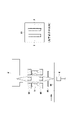
- the configuration shown in FIG. 6 may be used as a configuration for dispersing the X-rays from the X-ray source 2 into X-rays of one energy range and irradiating the sample W with the X-rays.
- the configuration shown in FIG. 6 places two identical optical elements 3 opposite each other.
- the two optical elements 3 are curved spectroscopic elements that disperse (monochromatic) X-rays in the same energy range and converge them linearly.
- the two optical elements 3 are arranged so that the X-rays condensed in a line by each optical element 3 coincide with each other on the sample W. As shown in FIG.
- a first collimator 81 is provided between the X-ray source and the optical element 3 to remove X-rays that do not enter the optical element 3. Between the optical element 3 and the sample W, A second collimator 82 is provided to filter out X-rays other than those in the desired energy range. A third collimator 83 for removing unnecessary X-rays may be provided between the second collimator and the sample W, if necessary. With the configuration of the optical system as shown in FIG. 6, the intensity of X-rays with which the sample W is irradiated can be improved.
- the integrated dose of the transmitted X-ray detector can be increased without lengthening the counting time, and the contrast of the transmitted X-rays can be increased even if the wafer is transported at a higher speed than before. As a result, it is possible to improve the precision and speed of foreign matter inspection of a sample.
- a configuration that includes a notification unit that notifies the user by, for example, issuing an error when the foreign object detection unit detects a foreign object.
- the specimen W conveyed by the conveying mechanism 6 is inspected for foreign matter, but this is a stand-alone type in which the specimen is placed on a fixed inspection table and inspected for foreign matter. can be
- Reference numeral 100 Transmission X-ray inspection apparatus W...Sample 2...X-ray source 3 (3a, 3b).
- Optical element 4 ...Transmission X-ray detectors 4a, 4b...Transmission X-ray Detector 5 Signal processing device 51 Image processing unit 52 Display control unit
Landscapes
- Health & Medical Sciences (AREA)
- Physics & Mathematics (AREA)
- Life Sciences & Earth Sciences (AREA)
- Chemical & Material Sciences (AREA)
- Analytical Chemistry (AREA)
- Biochemistry (AREA)
- General Health & Medical Sciences (AREA)
- General Physics & Mathematics (AREA)
- Immunology (AREA)
- Pathology (AREA)
- Toxicology (AREA)
- Analysing Materials By The Use Of Radiation (AREA)
Abstract
本発明は、透過X線検査装置において試料中の異物の検出感度を向上するものであり、互いに異なる複数のエネルギ域を含むX線を発するX線源2と、X線から1つのエネルギ域のX線に分光し、試料Wに向けて集光する光学素子3と、試料Wを透過した透過X線を検出する透過X線検出器4とを備える。
Description
本発明は、透過X線検査装置、及び透過X線検査方法に関するものである。
従来、試料中の異物を検査するシステムとして、特許文献1に示すように、透過X線検査装置を用いたものがある。この透過X線検査装置は、X線発生器からのX線を試料に照射し、当該試料を透過した透過X線を検出して、異物を検査するものである。
しかしながら、X線発生器からのX線は広がりながら試料に照射されるため、試料に照射されるX線強度が弱く、結果として、試料を透過する透過X線の強度も弱くなってしまう。そのため、透過X線検出器の検出感度が低下してしまう。なお、透過X線検出器の検出感度を向上させるべく、積算線量を大きくするために計数時間を長くすることも考えられるが、試料1つ1つに対して異物検査の時間が長くなってしまう。
そこで、本発明は上述したような問題に鑑みてなされたものであり、透過X線検査装置において試料中の異物の検出感度を向上することをその主たる課題とするものである。
すなわち、本発明に係る透過X線検査装置は、互いに異なる複数のエネルギ域を含むX線を発するX線源と、前記X線から1つのエネルギ域のX線に分光するとともに試料に向けて集光する光学素子と、前記試料を透過した透過X線を検出する透過X線検出部とを備えることを特徴とする。
このような構成であれば、互いに異なる複数のエネルギ域を含むX線から1つのエネルギ域のX線に分光しつつ試料に向けて集光するので、試料に照射される1つのエネルギ域のX線の強度を向上させることができ、透過X線の濃淡(コントラスト)を大きくすることができる。その結果、透過X線検査装置において試料中の異物の検出感度を向上することができる。また、試料に照射される1つのエネルギ域のX線の強度を向上させることにより、試料1つ1つに対する異物検査の時間が短くすることができる。なお、本発明において、試料中の異物には、試料表面に付着した異物及び試料内部に含まれる異物を含む。
搬送機構により搬送される試料を効率よく検査するためには、前記光学素子は、前記1つのエネルギ域のX線をライン状に集光する湾曲分光素子であることが望ましい。
また、前記透過X線検出部は、前記ライン状に集光されたX線に対応して設けられたラインセンサであることが望ましい。ここで、試料に照射されるX線を漏れなく検出して検出精度を向上するためには、前記ラインセンサのピクセル幅は、前記ライン状に集光されたX線の幅と略同一であることが望ましい。
また、本発明の透過X線検査装置は、前記試料を搬送する搬送機構とともに用いられるものであり、前記光学素子及び前記透過X線検出部は、前記搬送機構により搬送される前記試料を挟んで配置されていることが望ましい。ここで、ライン状に集光されたX線の長手方向、及び、ラインセンサの長手方向は、搬送機構の搬送方向に直交した方向とすることが望ましい。
この構成であれば、試料が搬送機構により搬送されるシステムにおいて、搬送される試料に照射される1つのエネルギ域のX線の強度を向上させることができる。その結果、透過X線検出部の積算線量を、計数時間を長くすることなく大きくすることができ、従来よりも高速に搬送しても透過X線の濃淡(コントラスト)を大きくすることができる。その結果、試料の異物検査の高速化を図ることができる。
この構成であれば、試料が搬送機構により搬送されるシステムにおいて、搬送される試料に照射される1つのエネルギ域のX線の強度を向上させることができる。その結果、透過X線検出部の積算線量を、計数時間を長くすることなく大きくすることができ、従来よりも高速に搬送しても透過X線の濃淡(コントラスト)を大きくすることができる。その結果、試料の異物検査の高速化を図ることができる。
検出対象となる異物の検出感度を向上させるためには、前記光学素子は、前記試料中の検出対象となる異物のX線吸収端よりも高いエネルギ域のX線に分光するものであることが望ましい。ここで、異物のX線吸収端は、例えばK吸収端又はL1吸収端、L2吸収端又はL3吸収端を含む概念であり、異物に応じてX線吸収端が選択され、それに応じて光学素子が選択される。例えば異物が銅の場合には、K吸収端を選択することができる。
試料に照射するX線の強度を向上させるためには、前記X線から同じエネルギ域のX線に分光するとともに試料に向けて集光する2つの光学素子を備えていることが望ましい。
この構成であれば、透過X線検出部の積算線量を、計数時間を長くすることなく大きくすることができ、従来よりも高速に搬送しても透過X線の濃淡(コントラスト)を大きくすることができる。その結果、試料の異物検査の高精度化、高速化を図ることができる。
この構成であれば、透過X線検出部の積算線量を、計数時間を長くすることなく大きくすることができ、従来よりも高速に搬送しても透過X線の濃淡(コントラスト)を大きくすることができる。その結果、試料の異物検査の高精度化、高速化を図ることができる。
1種類の異物の検出感度を向上させるため、又は、複数種類の異物を検出できるようにするためには、本発明の透過X線検査装置は、前記光学素子を複数種類有し、前記複数種類の光学素子は、互いに異なるエネルギ域のX線に分光するものであることが望ましい。
1種類の異物の検出感度を向上させるための具体的な実施の態様としては、前記光学素子を2種類有し、2種類のうちの一方の前記光学素子は、前記試料中の検出対象となる異物のX線吸収端よりも高いエネルギ域のX線に分光するものであり、2種類のうちの他方の前記光学素子は、前記X線吸収端よりも低いエネルギ域のX線に分光するものであることが望ましい。
ここで、前記複数種類の光学素子は、1つの前記X線源からのX線を、互いに異なるエネルギ域のX線に分光するものであることが望ましい。この構成であれば、複数種類の光学素子それぞれに対応して複数のX線源を設ける必要がなく、装置を小型化することができる。
複数種類の光学素子を用いて互いに異なるエネルギ域のX線に分光する構成において、透過X線検出部の具体的な実施の態様としては、前記透過X線検出部は、前記互いに異なるエネルギ域のX線それぞれに対応する複数の透過X線画像を生成するための複数の透過X線検出器を有することが望ましい。
異物の検出精度を向上するためには、本発明の透過X線検査装置は、前記複数の透過X線検出器それぞれを用いて生成された透過X線画像を処理する画像処理部をさらに備え、前記画像処理部は、前記互いに異なるエネルギ域のX線それぞれに対応する複数の透過X線画像を用いて差分処理を行い、前記試料中の異物を検出することが望ましい。
検出した異物をユーザに視認しやすくするためには、本発明の透過X線検査装置は、前記透過X線画像をディスプレイに表示させる表示制御部をさらに備え、前記表示制御部は、前記画像処理部により検出された前記異物に色を付けて表示させることが望ましい。
互いに異なる第1異物及び第2異物を検査するための具体的な実施の態様としては、前記光学素子は、前記第1異物のX線吸収端よりも低いエネルギ域の第1X線に分光する第1光学素子と、前記第1異物のX線吸収端よりも高いエネルギ域であり、且つ、前記第2異物のX線吸収端よりも低いエネルギ域の第2X線に分光する第2光学素子と、前記第2異物のX線吸収端よりも高いエネルギ域の第3X線に分光する第3光学素子とを有し、前記画像処理部は、前記第1X線を照射して得られた第1透過X線画像と、前記第2X線を照射して得られた第2透過X線画像と、前記第3X線を照射して得られた第3透過X線画像とを用いて差分処理を行い、前記第1異物及び第2異物を検出することが望ましい。
複数種類の光学素子を配置した場合には、X線源及び透過X線検出部との位置関係が光学素子毎に異なるため、試料に照射されるX線強度が異なってしまう。このため、本発明の透過X線検査装置は、前記複数種類の光学素子それぞれから前記試料に照射されるX線強度の違いを補正する補正部をさらに備えることが望ましい。
また、本発明に係る透過X線検査方法は、X線源から発せされる互いに異なる複数のエネルギ域を含むX線を、光学素子によって1つのエネルギ域のX線に分光するとともに試料に向けて集光し、前記試料を透過した透過X線を透過X線検出部によって検出することを特徴とする。
以上に述べた本発明によれば、透過X線検査装置において試料中の異物の検出感度を向上することができる。
以下に、本発明に係る透過X線検査装置の一実施形態について、図面を参照して説明する。なお、以下に示すいずれの図についても、わかりやすくするために、適宜省略し又は誇張して模式的に描かれている。同一の構成要素については、同一の符号を付して説明を適宜省略する。
本実施形態の透過X線検査装置100は、図1及び図2に示すように、一次X線を発するX線源2と、一次X線を分光しつつ試料Wに向けて集光する光学素子3と、試料Wを透過した透過X線を検出する透過X線検出部4と、透過X線検出部4からの検出信号を処理する信号処理装置5とを備えている。
また、本実施形態の透過X線検査装置100は、検査対象である試料Wを所定方向(図2において紙面左右方向であり、ここではX方向)に搬送させる搬送機構6を有している。そして、光学素子3及び透過X線検出部4は、搬送機構6により搬送される試料Wを上下から挟んで配置されている。この構成により、本実施形態の透過X線検査装置100は、搬送機構6で試料Wを搬送しながら試料Wの異物検査を行うことができる。また、透過X線検査装置100は、例えば基材に膜材を塗布する膜材塗布装置7に組み込んだインラインシステムとすることができる。なお、本実施形態の試料Wは、例えばリチウムイオン電池の正極材であり、検出対象である異物Sは、銅(K吸収端のエネルギーは8.98keV)である。
X線源2は、互いに異なる複数のエネルギ域(波長域)を含む一次X線(多色X線)を発するものである。具体的にX線源2は、フィラメントを加熱することで発生した電子をタングステンやモリブデンなどのターゲット金属に衝突させることで連続X線と特性X線を発生するX線管である。なお、本実施形態のターゲット金属は、タングステンである。
光学素子3は、一次X線から1つのエネルギ域(1つの波長域)のX線に分光しつつ試料Wに向けて集光するものである。ここで、1つのエネルギ域(1つの波長域)は、検出対象である異物Sの透過率、特にX線吸収端(ここでは銅のK吸収端)に基づいて設定されるものである。
具体的に光学素子3は、1つのエネルギ域のX線に分光する(単色化する)と同時にライン状に集光する湾曲分光素子である。ここで、光学素子3aによりライン状に集光されたX線の長手方向は、搬送機構6の搬送方向に直交した方向(Y方向)である。この湾曲分光素子を用いることにより、広がりを持って入射してきた一次X線を湾曲した結晶表面でブラッグ反射させて所定の位置(ここでは試料Wの上面)に集光させ、所定のエネルギ域のX線のみを取り出すことができる。湾曲分光素子の材料としては、シリコン、グラファイト、フッ化リチウム等の分光結晶として用いられるものを挙げることができる。湾曲分光素子として、2種類の分光結晶を組み合わせて構成する場合には、分光する波長は分光結晶の湾曲具合(ローランド円のサイズ)を変えて集光するX線波長を変える。また、分光する波長は分光結晶の湾曲具合(ローランド円のサイズ)及び/又は分光結晶の材質を変えて集光するX線波長を変えることもできる。本実施形態の光学素子3は、タングステンの蛍光X線のLβ(高エネルギ;9.67~9.96keV)とLα(低エネルギ;8.40keV)とを分光して集光する。
本実施形態では、図1及び図2に示すように、互いに異なるエネルギ域のX線に分光する複数種類(ここでは2種類)の光学素子3a、3bを有している。2種類のうちの一方の光学素子3aは、高エネルギ域のX線に分光しつつ試料Wに集光する。また、2種類のうちの他方の光学素子3bは、低エネルギ域のX線に分光しつつ試料Wに集光するものである。
ここで、図3に示すように、一方の光学素子3aにより分光されたX線は、試料W中の検出対象となる異物SのX線吸収端よりも高いエネルギ域のX線である。また、他方の光学素子3bにより分光されたX線は、試料W中の検出対象となる異物SのX線吸収端よりも低いエネルギ域のX線である。
透過X線検出部4は、試料Wを透過した透過X線を検出するものであり、図1及び図2に示すように、試料Wの下面側に設けられたラインセンサからなる透過X線検出器4a、4bを用いて構成されている。この透過X線検出器4a、4bは、ライン状に集光されたX線に対応して設けられている。つまり、透過X線検出器4a、4bの長手方向は、搬送機構6の搬送方向に直交した方向(Y方向)である。さらに、透過X線検出器4a、4bのピクセル幅は、ライン状に集光されたX線の幅と略同一である。
本実施形態の透過X線検出部4は、互いに異なるエネルギ域のX線それぞれに対応する複数の透過X線画像を生成するための複数(ここでは2つ)の透過X線検出器4a、4bを有している。一方の透過X線検出器4aは、一方の光学素子3aに対応して設けられたラインセンサであり、高エネルギ域のX線が照射された試料Wからの透過X線を検出する。また、他方の透過X線検出器4bは、他方の光学素子3bに対応して設けられたラインセンサであり、低エネルギ域のX線が照射された試料Wからの透過X線を検出する。なお、各ラインセンサは、ライン状に設けられたシンチレータと、当該シンチレータのX線入射側の前方に設けられたX線フィルタとを有している。なお、X線フィルタは、検出すべき透過X線を透過しつつ、外乱となるその他のX線を遮断するものである。また、ラインセンサは、半導体放射線検出器(SDD)又は光電子増倍管などを用いた構成としても良い。
信号処理装置5は、透過X線検出部4からの検出信号を処理して、透過X線画像を生成するとともに、透過X線画像から異物を検出するものである。具体的に信号処理装置は、CPU、メモリ、入出力インターフェイス、ディスプレイ50、入力手段等を有するコンピュータであり、図4に示すように、画像生成部5a、画像処理部5b、異物検出部5c及び表示制御部5d等の機能を有している。
画像生成部5aは、複数の透過X線検出器4a、4bからの検出信号を取得して、複数の透過X線画像を生成するものである。本実施形態では、一方の透過X線検出器4aからの検出信号を用いて、高エネルギ域の透過X線画像を生成し、他方の透過X線検出器4bからの検出信号を用いて、低エネルギ域の透過X線画像を生成する。画像生成部5aにより生成された透過X線画像は、画像処理部5bに送信されるとともに、表示制御部5dに送信される。
画像処理部5bは、画像生成部5aにより生成された高エネルギ域の透過X線画像及び低エネルギ域の透過X線画像を用いて、差分処理を行い、試料W中の異物を検出する。この画像処理部5bは、高エネルギ域の透過X線画像と低エネルギ域の透過X線画像との差分画像を生成して、透過X線画像の濃淡(コントラスト)を大きくして、異物Sを抽出しやすくする。画像処理部5bにより生成された差分画像は、異物検出部5cに送信されるとともに、表示制御部5dに送信される。
異物検出部5cは、画像処理部5bの差分処理により生成された差分画像から、異物Sを検出するものである。この異物検出部5cは、例えば、差分画像から異物サイズを求めて、当該異物サイズが例えば面積相当径で20μm以上の場合に異物をして検出する。この異物検出部5cにより検出された異物を示す異物情報は、表示制御部5dに送信される。なお、異物情報は、異物が検出された画像データであり、当該画像データは、信号処理装置5のメモリにも保存される。また、異物検出部5cは、管制室のサーバ(上位制御装置)等に異物を検出したことを示すエラー情報とともに画像データを送信することもできる。
表示制御部5dは、異物検出部5cにより検出された異物Sをディスプレイ50に表示させるものである。具体的に表示制御部5dは、画像処理部5bにより生成された差分画像と検出された異物とを重ねてディスプレイ50に表示させる。ここで、表示制御部5dは、検出された異物に色を付けて表示する等のようにユーザが視認しやすい態様で検出された異物を表示させることができる。
その他、表示制御部5dは、画像生成部5aにより生成された各エネルギ域のX線透過画像、又は、画像処理部5bにより生成された差分画像をディスプレイ50に表示することもできる。さらに、表示制御部5dは、画像生成部5aにより生成された各エネルギ域のX線透過画像と検出された異物とを重ねてディスプレイ50に表示させることもできる。
<本実施形態の効果>
このように構成した本実施形態の透過X線検査装置100によれば、互いに異なる複数のエネルギ域を含むX線から1つのエネルギ域のX線に分光しつつ試料Wに向けて集光するので、試料Wに照射される1つのエネルギ域のX線の強度を向上させることができ、透過X線の濃淡(コントラスト)を大きくすることができる。その結果、透過X線検査装置100において試料W中の異物Sの検出感度を向上することができる。また、試料Wに照射される1つのエネルギ域のX線の強度を向上させることにより、試料W1つ1つに対する異物検査の時間が短くすることができる。
このように構成した本実施形態の透過X線検査装置100によれば、互いに異なる複数のエネルギ域を含むX線から1つのエネルギ域のX線に分光しつつ試料Wに向けて集光するので、試料Wに照射される1つのエネルギ域のX線の強度を向上させることができ、透過X線の濃淡(コントラスト)を大きくすることができる。その結果、透過X線検査装置100において試料W中の異物Sの検出感度を向上することができる。また、試料Wに照射される1つのエネルギ域のX線の強度を向上させることにより、試料W1つ1つに対する異物検査の時間が短くすることができる。
また、試料Wが搬送機構66により搬送されるシステムにおいて、搬送される試料Wに照射される1つのエネルギ域のX線の強度を向上させることができる。その結果、透過X線検出部4の積算線量を、計数時間を長くすることなく大きくすることができ、従来よりも高速に搬送しても透過X線の濃淡(コントラスト)を大きくすることができる。その結果、試料Wの異物検査の高速化を図ることができる。
<その他の実施形態>
例えば、前記実施形態では1種類の異物を検出対象としていたが、2種類以上の異物を検出対象としても良い。具体的に、互いに異なる種類の第1異物及び第2異物を検査する場合には、光学素子3は、第1異物のX線吸収端よりも低いエネルギ域の第1X線(図5参照)に分光する第1光学素子と、第1異物のX線吸収端よりも高いエネルギ域であり、且つ、第2異物のX線吸収端よりも低いエネルギ域の第2X線(図5参照)に分光する第2光学素子と、第2異物のX線吸収端よりも高いエネルギ域の第3X線(図5参照)に分光する第3光学素子とを含む。なお、第1~第3光学素子は、前記実施形態と同様に、湾曲分光素子である。また、これら3つの光学素子に対応して、透過X線検出部4は、3つの透過X線検出器を有している。
例えば、前記実施形態では1種類の異物を検出対象としていたが、2種類以上の異物を検出対象としても良い。具体的に、互いに異なる種類の第1異物及び第2異物を検査する場合には、光学素子3は、第1異物のX線吸収端よりも低いエネルギ域の第1X線(図5参照)に分光する第1光学素子と、第1異物のX線吸収端よりも高いエネルギ域であり、且つ、第2異物のX線吸収端よりも低いエネルギ域の第2X線(図5参照)に分光する第2光学素子と、第2異物のX線吸収端よりも高いエネルギ域の第3X線(図5参照)に分光する第3光学素子とを含む。なお、第1~第3光学素子は、前記実施形態と同様に、湾曲分光素子である。また、これら3つの光学素子に対応して、透過X線検出部4は、3つの透過X線検出器を有している。
そして、画像処理部5bは、第1X線を照射して得られた第1透過X線画像と、第2X線を照射して得られた第2透過X線画像と、第3X線を照射して得られた第3透過X線画像とを用いて差分処理を行い、第1異物及び第2異物を検出する。具体的には、第2X線画像と第1X線画像との差分処理により第1異物を検出し、第3X線画像と第2X線画像との差分処理により第2異物を検出する。表示制御部5dは、それぞれの検出した第1異物及び第2異物を別々に表示させても良いし、第1異物及び第2異物を1つの画像の中でそれぞれの異物を異なる色で色分けしてもよい。なお、第1異物については、第3X線画像と第1X線画像との差分処理により検出してもよい。
また、信号処理装置5は、複数の光学素子3それぞれから試料Wに照射されるX線強度の違いを補正する補正部をさらに備えていても良い。この補正部は、X線源2及び透過X線検出部4と複数の光学素子3との光学配置に基づいて、画像生成部5aにおける透過X画像を生成する際に用いるパラメータを補正するものであっても良い。また、補正部は、X線源2及び透過X線検出部4と複数の光学素子3との光学配置に基づいて、複数の透過X線画像を補正するものであっても良い。
さらに、信号処理装置5は、複数の透過X線検出器4a、4bそれぞれの検出感度を合わせるように補正する感度補正部をさらに備えていても良い。
その上、前記実施形態では1つのX線源2からのX線を複数の光学素子3により互いに異なるエネルギ域のX線に分光する構成であったが、複数のX線源2を備えていても良い。例えば、複数の光学素子3それぞれに対応してX線源2を設けても良い。
また、前記実施形態では、複数の光学素子及び複数の透過X線検出器を有する構成であったが、1つの光学素子及び1つの透過X線検出器を有する構成であっても良い。この場合、光学素子は、異物のK吸収端よりも高いエネルギのX線を分光して集光することが考えられる。
さらに、X線源2からのX線を1つのエネルギ域のX線に分光して試料Wに照射する構成としては、図6に示す構成であっても良い。図6に示す構成は、2つの同じ光学素子3を互いに対向するように配置する。ここで、2つの光学素子3は、同一のエネルギ域のX線に分光する(単色化する)と同時にライン状に集光する湾曲分光素子である。そして、2つの光学素子3は、各光学素子3によりライン状に集光されたX線が互いに試料W上で一致するように配置されている。また、X線源と光学素子3との間には、光学素子3に入射しないX線を除去するための第1コリメータ81が設けられており、光学素子3と試料Wとの間には、所望のエネルギ域のX線以外のX線を除去するための第2コリメータ82が設けられている。また、第2コリメータと試料Wとの間には、必要に応じて不要なX線を除去するための第3コリメータ83を設けても良い。図6に示すような光学系の構成により、試料Wに照射するX線の強度を向上させることができる。その結果、透過X線検出部の積算線量を、計数時間を長くすることなく大きくすることができ、従来よりも高速に搬送しても透過X線の濃淡(コントラスト)を大きくすることができる。その結果、試料の異物検査の高精度化、高速化を図ることができる。
その上、前記実施形態の構成に加えて、異物検出部が異物を検出した場合に、エラーを出すなどのようにユーザに報知する報知部を有する構成としても良い。
加えて、前記実施形態では、搬送機構6により搬送される試料Wの異物検査を行うものであったが、固定された検査テーブルに試料を設置して異物検査を行うスタンドアローンタイプのものであっても良い。
その他、本発明の趣旨に反しない限りにおいて様々な実施形態の変形や組み合わせを行っても構わない。
本発明によれば、透過X線検査装置において試料中の異物の検出感度を向上することができる。
100・・・透過X線検査装置
W・・・試料
2・・・X線源
3(3a、3b)・・・光学素子
4・・・透過X線検出部
4a、4b・・・透過X線検出器
5・・・信号処理装置
51・・・画像処理部
52・・・表示制御部
W・・・試料
2・・・X線源
3(3a、3b)・・・光学素子
4・・・透過X線検出部
4a、4b・・・透過X線検出器
5・・・信号処理装置
51・・・画像処理部
52・・・表示制御部
Claims (15)
- 互いに異なる複数のエネルギ域を含むX線を発するX線源と、
前記X線から1つのエネルギ域のX線に分光するとともに試料に向けて集光する光学素子と、
前記試料を透過した透過X線を検出する透過X線検出部とを備える、透過X線検査装置。 - 前記光学素子は、前記1つのエネルギ域のX線をライン状に集光する湾曲分光素子である、請求項1に記載の透過X線検査装置。
- 前記透過X線検出部は、前記ライン状に集光されたX線に対応して設けられたラインセンサである、請求項2に記載の透過X線検査装置。
- 前記試料を搬送する搬送機構とともに用いられるものであり、
前記光学素子及び前記透過X線検出部は、前記搬送機構により搬送される前記試料を挟んで配置されている、請求項1乃至3の何れか一項に記載の透過X線検査装置。 - 前記光学素子は、前記試料中の検出対象となる異物のX線吸収端よりも高いエネルギ域のX線に分光するものである、請求項1乃至4の何れか一項に記載の透過X線検査装置。
- 前記X線から同じエネルギ域のX線に分光するとともに試料に向けて集光する2つの光学素子を備えている、請求項1乃至5の何れか一項に記載の透過X線検査装置。
- 前記光学素子を複数種類有し、
前記複数種類の光学素子は、互いに異なるエネルギ域のX線に分光するものである、請求項1乃至6の何れか一項に記載の透過X線検査装置。 - 前記光学素子を2種類有し、
2種類のうちの一方の前記光学素子は、前記試料中の検出対象となる異物のX線吸収端よりも高いエネルギ域のX線に分光するものであり、
2種類のうちの他方の前記光学素子は、前記X線吸収端よりも低いエネルギ域のX線に分光するものである、請求項7に記載の透過X線検査装置。 - 前記複数種類の光学素子は、1つの前記X線源からのX線を、互いに異なるエネルギ域のX線に分光するものである、請求項7又は8に記載の透過X線検査装置。
- 前記透過X線検出部は、前記互いに異なるエネルギ域のX線それぞれに対応する複数の透過X線画像を生成するための複数の透過X線検出器を有する、請求項7乃至9の何れか一項に記載の透過X線検査装置。
- 前記複数の透過X線検出器それぞれを用いて生成された透過X線画像を処理する画像処理部をさらに備え、
前記画像処理部は、前記互いに異なるエネルギ域のX線それぞれに対応する複数の透過X線画像を用いて差分処理を行い、前記試料中の異物を検出する、請求項10に記載の透過X線検査装置。 - 前記透過X線画像をディスプレイに表示させる表示制御部をさらに備え、
前記表示制御部は、前記画像処理部により検出された前記異物に色を付けて表示させる、請求項11に記載の透過X線検査装置。 - 互いに異なる種類の第1異物及び第2異物を検査するものであり、
前記光学素子は、前記第1異物のX線吸収端よりも低いエネルギ域の第1X線に分光する第1光学素子と、前記第1異物のX線吸収端よりも高いエネルギ域であり、且つ、前記第2異物のX線吸収端よりも低いエネルギ域の第2X線に分光する第2光学素子と、前記第2異物のX線吸収端よりも高いエネルギ域の第3X線に分光する第3光学素子とを含み、
前記画像処理部は、前記第1X線を照射して得られた第1透過X線画像と、前記第2X線を照射して得られた第2透過X線画像と、前記第3X線を照射して得られた第3透過X線画像とを用いて差分処理を行い、前記第1異物及び第2異物を検出する、請求項9又は10に記載の透過X線検査装置。 - 前記複数種類の光学素子それぞれから前記試料に照射されるX線強度の違いを補正する補正部をさらに備える、請求項7乃至13の何れか一項に記載の透過X線検査装置。
- X線源から発せされる互いに異なる複数のエネルギ域を含むX線を、光学素子によって1つのエネルギ域のX線に分光するとともに試料に向けて集光し、
前記試料を透過した透過X線を透過X線検出部によって検出する、透過X線検査方法。
Priority Applications (3)
| Application Number | Priority Date | Filing Date | Title |
|---|---|---|---|
| JP2023531997A JPWO2023277039A1 (ja) | 2021-06-30 | 2022-06-28 | |
| DE112022003317.7T DE112022003317T5 (de) | 2021-06-30 | 2022-06-28 | Transmissions-röntgenprüfvorrichtung und transmissions-röntgenprüfverfahren |
| CN202280044285.1A CN117546011A (zh) | 2021-06-30 | 2022-06-28 | 透射x射线检查装置和透射x射线检查方法 |
Applications Claiming Priority (2)
| Application Number | Priority Date | Filing Date | Title |
|---|---|---|---|
| JP2021108333 | 2021-06-30 | ||
| JP2021-108333 | 2021-06-30 |
Publications (1)
| Publication Number | Publication Date |
|---|---|
| WO2023277039A1 true WO2023277039A1 (ja) | 2023-01-05 |
Family
ID=84691447
Family Applications (1)
| Application Number | Title | Priority Date | Filing Date |
|---|---|---|---|
| PCT/JP2022/025838 WO2023277039A1 (ja) | 2021-06-30 | 2022-06-28 | 透過x線検査装置、及び透過x線検査方法 |
Country Status (4)
| Country | Link |
|---|---|
| JP (1) | JPWO2023277039A1 (ja) |
| CN (1) | CN117546011A (ja) |
| DE (1) | DE112022003317T5 (ja) |
| WO (1) | WO2023277039A1 (ja) |
Citations (6)
| Publication number | Priority date | Publication date | Assignee | Title |
|---|---|---|---|---|
| US5596620A (en) * | 1993-04-30 | 1997-01-21 | The University Of Connecticut | X-ray based extensometry device for radiography |
| JPH10318943A (ja) * | 1997-05-20 | 1998-12-04 | Shimadzu Corp | 異物検査装置 |
| JP2009178517A (ja) * | 2008-02-01 | 2009-08-13 | Ge Medical Systems Global Technology Co Llc | 画像処理装置及びx線ct装置 |
| KR20120013724A (ko) * | 2010-08-06 | 2012-02-15 | 라드텍주식회사 | 이중 에너지 x-선 흡광분석을 이용한 x-선 영상장치 |
| JP2018031643A (ja) * | 2016-08-24 | 2018-03-01 | 株式会社日立ハイテクサイエンス | X線透過検査装置 |
| JP2018130336A (ja) * | 2017-02-15 | 2018-08-23 | キヤノン株式会社 | 放射線撮影装置、放射線撮影システム、放射線撮影方法、及びプログラム |
Family Cites Families (1)
| Publication number | Priority date | Publication date | Assignee | Title |
|---|---|---|---|---|
| JP6663374B2 (ja) | 2017-02-28 | 2020-03-11 | アンリツインフィビス株式会社 | X線検査装置 |
-
2022
- 2022-06-28 DE DE112022003317.7T patent/DE112022003317T5/de active Pending
- 2022-06-28 WO PCT/JP2022/025838 patent/WO2023277039A1/ja active Application Filing
- 2022-06-28 JP JP2023531997A patent/JPWO2023277039A1/ja active Pending
- 2022-06-28 CN CN202280044285.1A patent/CN117546011A/zh active Pending
Patent Citations (6)
| Publication number | Priority date | Publication date | Assignee | Title |
|---|---|---|---|---|
| US5596620A (en) * | 1993-04-30 | 1997-01-21 | The University Of Connecticut | X-ray based extensometry device for radiography |
| JPH10318943A (ja) * | 1997-05-20 | 1998-12-04 | Shimadzu Corp | 異物検査装置 |
| JP2009178517A (ja) * | 2008-02-01 | 2009-08-13 | Ge Medical Systems Global Technology Co Llc | 画像処理装置及びx線ct装置 |
| KR20120013724A (ko) * | 2010-08-06 | 2012-02-15 | 라드텍주식회사 | 이중 에너지 x-선 흡광분석을 이용한 x-선 영상장치 |
| JP2018031643A (ja) * | 2016-08-24 | 2018-03-01 | 株式会社日立ハイテクサイエンス | X線透過検査装置 |
| JP2018130336A (ja) * | 2017-02-15 | 2018-08-23 | キヤノン株式会社 | 放射線撮影装置、放射線撮影システム、放射線撮影方法、及びプログラム |
Also Published As
| Publication number | Publication date |
|---|---|
| DE112022003317T5 (de) | 2024-04-11 |
| CN117546011A (zh) | 2024-02-09 |
| JPWO2023277039A1 (ja) | 2023-01-05 |
Similar Documents
| Publication | Publication Date | Title |
|---|---|---|
| US20130195244A1 (en) | X-Ray Inspector | |
| US8068583B2 (en) | X-ray analysis apparatus and X-ray analysis method | |
| JP6397690B2 (ja) | X線透過検査装置及び異物検出方法 | |
| US9164045B2 (en) | Phase imaging | |
| Colón et al. | Constraining the false positive rate for Kepler planet candidates with multicolour photometry from the GTC | |
| CN109196340B (zh) | 波长分散型荧光x射线分析装置和采用它的荧光x射线分析方法 | |
| JP2012513023A5 (ja) | ||
| JP4853964B2 (ja) | X線検査装置用のx線センサ | |
| US20210255343A1 (en) | X-Ray Detectors of High Spatial Resolution | |
| García-Bernete et al. | The nuclear and extended mid-infrared emission of Seyfert galaxies | |
| JP2011242374A (ja) | X線検査装置 | |
| Kosenkov et al. | High-precision optical polarimetry of the accreting black hole V404 Cyg during the 2015 June outburst | |
| Romano et al. | A new X-ray pinhole camera for energy dispersive X-ray fluorescence imaging with high-energy and high-spatial resolution | |
| CN109791116B (zh) | 波长色散型荧光x射线分析装置 | |
| KR20160067527A (ko) | 미세패턴 측정용 Micro-XRF 장치 및 방법 | |
| JP2011043474A (ja) | X線検出器およびx線検査装置 | |
| US20200271600A1 (en) | Semiconductor defect inspection apparatus and semiconductor defect inspection method | |
| WO2023277039A1 (ja) | 透過x線検査装置、及び透過x線検査方法 | |
| Eckel et al. | Radiographic film system classification and noise characterisation by a camera-based digitisation procedure | |
| JP2019203853A (ja) | X線ラインセンサ及びそれを用いたx線異物検出装置 | |
| JP2011099725A (ja) | 物品検査装置 | |
| JP2007064727A (ja) | X線検査装置とx線検査方法 | |
| JP6191051B2 (ja) | 蛍光x線分析装置 | |
| JP6506629B2 (ja) | X線受光装置およびこれを備えたx線検査装置 | |
| Schumacher et al. | Influencing parameters on image quality using photon counting detectors for laminography |
Legal Events
| Date | Code | Title | Description |
|---|---|---|---|
| 121 | Ep: the epo has been informed by wipo that ep was designated in this application |
Ref document number: 22833185 Country of ref document: EP Kind code of ref document: A1 |
|
| WWE | Wipo information: entry into national phase |
Ref document number: 2023531997 Country of ref document: JP |
|
| WWE | Wipo information: entry into national phase |
Ref document number: 202280044285.1 Country of ref document: CN |
|
| WWE | Wipo information: entry into national phase |
Ref document number: 112022003317 Country of ref document: DE |