WO2023234113A1 - 電気接続箱 - Google Patents
電気接続箱 Download PDFInfo
- Publication number
- WO2023234113A1 WO2023234113A1 PCT/JP2023/019101 JP2023019101W WO2023234113A1 WO 2023234113 A1 WO2023234113 A1 WO 2023234113A1 JP 2023019101 W JP2023019101 W JP 2023019101W WO 2023234113 A1 WO2023234113 A1 WO 2023234113A1
- Authority
- WO
- WIPO (PCT)
- Prior art keywords
- fuse
- small
- output side
- input side
- side fixing
- Prior art date
- Legal status (The legal status is an assumption and is not a legal conclusion. Google has not performed a legal analysis and makes no representation as to the accuracy of the status listed.)
- Ceased
Links
Images



Classifications
-
- H—ELECTRICITY
- H02—GENERATION; CONVERSION OR DISTRIBUTION OF ELECTRIC POWER
- H02G—INSTALLATION OF ELECTRIC CABLES OR LINES, OR OF COMBINED OPTICAL AND ELECTRIC CABLES OR LINES
- H02G3/00—Installations of electric cables or lines or protective tubing therefor in or on buildings, equivalent structures or vehicles
- H02G3/02—Details
- H02G3/08—Distribution boxes; Connection or junction boxes
- H02G3/16—Distribution boxes; Connection or junction boxes structurally associated with support for line-connecting terminals within the box
-
- B—PERFORMING OPERATIONS; TRANSPORTING
- B60—VEHICLES IN GENERAL
- B60R—VEHICLES, VEHICLE FITTINGS, OR VEHICLE PARTS, NOT OTHERWISE PROVIDED FOR
- B60R16/00—Electric or fluid circuits specially adapted for vehicles and not otherwise provided for; Arrangement of elements of electric or fluid circuits specially adapted for vehicles and not otherwise provided for
- B60R16/02—Electric or fluid circuits specially adapted for vehicles and not otherwise provided for; Arrangement of elements of electric or fluid circuits specially adapted for vehicles and not otherwise provided for electric constitutive elements
- B60R16/023—Electric or fluid circuits specially adapted for vehicles and not otherwise provided for; Arrangement of elements of electric or fluid circuits specially adapted for vehicles and not otherwise provided for electric constitutive elements for transmission of signals between vehicle parts or subsystems
- B60R16/0238—Electrical distribution centers
-
- B—PERFORMING OPERATIONS; TRANSPORTING
- B60—VEHICLES IN GENERAL
- B60R—VEHICLES, VEHICLE FITTINGS, OR VEHICLE PARTS, NOT OTHERWISE PROVIDED FOR
- B60R16/00—Electric or fluid circuits specially adapted for vehicles and not otherwise provided for; Arrangement of elements of electric or fluid circuits specially adapted for vehicles and not otherwise provided for
- B60R16/02—Electric or fluid circuits specially adapted for vehicles and not otherwise provided for; Arrangement of elements of electric or fluid circuits specially adapted for vehicles and not otherwise provided for electric constitutive elements
- B60R16/023—Electric or fluid circuits specially adapted for vehicles and not otherwise provided for; Arrangement of elements of electric or fluid circuits specially adapted for vehicles and not otherwise provided for electric constitutive elements for transmission of signals between vehicle parts or subsystems
- B60R16/0239—Electronic boxes
-
- H—ELECTRICITY
- H01—ELECTRIC ELEMENTS
- H01H—ELECTRIC SWITCHES; RELAYS; SELECTORS; EMERGENCY PROTECTIVE DEVICES
- H01H85/00—Protective devices in which the current flows through a part of fusible material and this current is interrupted by displacement of the fusible material when this current becomes excessive
- H01H85/02—Details
- H01H85/20—Bases for supporting the fuse; Separate parts thereof
-
- H—ELECTRICITY
- H01—ELECTRIC ELEMENTS
- H01H—ELECTRIC SWITCHES; RELAYS; SELECTORS; EMERGENCY PROTECTIVE DEVICES
- H01H85/00—Protective devices in which the current flows through a part of fusible material and this current is interrupted by displacement of the fusible material when this current becomes excessive
- H01H85/02—Details
- H01H85/20—Bases for supporting the fuse; Separate parts thereof
- H01H85/2045—Mounting means or insulating parts of the base, e.g. covers, casings
-
- H—ELECTRICITY
- H01—ELECTRIC ELEMENTS
- H01H—ELECTRIC SWITCHES; RELAYS; SELECTORS; EMERGENCY PROTECTIVE DEVICES
- H01H85/00—Protective devices in which the current flows through a part of fusible material and this current is interrupted by displacement of the fusible material when this current becomes excessive
- H01H85/02—Details
- H01H85/20—Bases for supporting the fuse; Separate parts thereof
- H01H85/205—Electric connections to contacts on the base
-
- H—ELECTRICITY
- H05—ELECTRIC TECHNIQUES NOT OTHERWISE PROVIDED FOR
- H05K—PRINTED CIRCUITS; CASINGS OR CONSTRUCTIONAL DETAILS OF ELECTRIC APPARATUS; MANUFACTURE OF ASSEMBLAGES OF ELECTRICAL COMPONENTS
- H05K7/00—Constructional details common to different types of electric apparatus
- H05K7/02—Arrangements of circuit components or wiring on supporting structure
- H05K7/06—Arrangements of circuit components or wiring on supporting structure on insulating boards, e.g. wiring harnesses
-
- B—PERFORMING OPERATIONS; TRANSPORTING
- B60—VEHICLES IN GENERAL
- B60R—VEHICLES, VEHICLE FITTINGS, OR VEHICLE PARTS, NOT OTHERWISE PROVIDED FOR
- B60R16/00—Electric or fluid circuits specially adapted for vehicles and not otherwise provided for; Arrangement of elements of electric or fluid circuits specially adapted for vehicles and not otherwise provided for
- B60R16/02—Electric or fluid circuits specially adapted for vehicles and not otherwise provided for; Arrangement of elements of electric or fluid circuits specially adapted for vehicles and not otherwise provided for electric constitutive elements
-
- H—ELECTRICITY
- H01—ELECTRIC ELEMENTS
- H01H—ELECTRIC SWITCHES; RELAYS; SELECTORS; EMERGENCY PROTECTIVE DEVICES
- H01H85/00—Protective devices in which the current flows through a part of fusible material and this current is interrupted by displacement of the fusible material when this current becomes excessive
- H01H85/02—Details
- H01H85/20—Bases for supporting the fuse; Separate parts thereof
- H01H2085/2075—Junction box, having holders integrated with several other holders in a particular wiring layout
- H01H2085/208—Junction box, having holders integrated with several other holders in a particular wiring layout specially adapted for vehicles
Definitions
- the present disclosure relates to an electrical connection box.
- an electrical junction box equipped with a fusible link an electrical junction box described in Japanese Patent Application Laid-Open No. 2005-185002 (Patent Document 1 below) is known.
- This electrical connection box includes a lower case and an upper case that is assembled over the upper surface of the lower case.
- the upper surface of the lower case includes an input side LA terminal connection section, an output side LA terminal connection section, a first fusible link mounting section adjacent to the LA terminal connection section, a second fusible link mounting section, and a plurality of relays.
- a housing section and a fuse housing section are provided.
- the fusible link mounted on the first fusible link mounting section includes a main body, an input terminal projecting laterally from the lower end of one side of the main body, and an input terminal projecting from the lower end of the other side of the main body. has an output terminal portion protruding in the opposite direction.
- the fusible link and the first fusible link mounting portion are fixed by passing a bolt through a bolt hole of the first fusible link mounting portion and a bolt hole of an input terminal portion of the fusible link and tightening it with a nut.
- the size of the fusible link installed may vary depending on the vehicle model and grade. For this reason, with conventional electrical junction boxes, it is necessary to design a dedicated electrical junction box for each size of fusible link, resulting in lack of versatility and high cost.
- An electrical junction box of the present disclosure includes a housing and a bus bar attached to the housing, the housing including at least two large fuses and a small fuse of different sizes.
- the fuse mounting portion includes a large input side fixing portion to which a large input terminal provided on one end side of the large fuse is fixed, and a large input side fixing portion to which a large input terminal provided on one end side of the large fuse is mounted.
- a large output side fixing part to which a large output terminal provided at the other end is fixed; a small input side fixing part to which a small input terminal provided at one end of the small fuse is fixed; a small output side fixing part to which a small output terminal provided on the other end side is fixed; the small input side fixing part and the small output side fixing part are connected to the large input side fixing part and the large output side fixing part; This is an electrical connection box placed between fixed parts.
- At least two fuses of different sizes can be mounted in the same electrical connection box, and costs can be reduced.
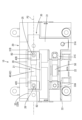
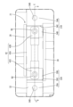
- FIG. 1 is a plan view of an electrical junction box in which a large fuse is mounted.
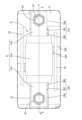
- FIG. 2 is a plan view of an electrical junction box in which small fuses are mounted.
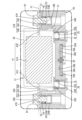
- FIG. 3 is a partially enlarged plan view of the electrical connection box showing an enlarged view of the fuse mounting portion in which a large fuse is mounted.
- FIG. 4 is a sectional view taken along line AA in FIG.
- FIG. 5 is a partially enlarged rear view of the electrical connection box showing an enlarged view of the fuse mounting portion in which a large fuse is mounted.
- FIG. 6 is a sectional view taken along line BB in FIG.
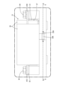
- FIG. 7 is a partially enlarged plan view of the electrical connection box showing an enlarged view of the fuse mounting portion in which the small fuses are mounted.
- FIG. 8 is a sectional view taken along the line CC in FIG.
- the electrical junction box of the present disclosure includes a housing and a bus bar attached to the housing, and the housing has large fuses and small fuses of different sizes.
- the bus bar has a large input side connecting portion fixed to the large input side fixing portion while connected to the large input terminal, and a large input side connecting portion fixed to the small input side fixing portion while connected to the small input terminal.
- an input side bus bar having a small input side connection part that is fixed; and a large output side connection part that is fixed to the large output side fixing part while being connected to the large output terminal; and a large output side connection part that is connected to the small output terminal. It is preferable to include an output side bus bar having a low output side connection part fixed to the low output side fixing part in the state.
- the large input side connection part and the small input side connection part are arranged at different height positions in a height direction perpendicular to the arrangement direction in plan view, and the input side bus bar is connected to the large input side connection part. and the small input side connection part are connected in a stepped manner, and the large output side connection part and the small output side connection part are arranged in a height direction perpendicular to the arrangement direction in a plan view.
- the output side bus bars are arranged at different height positions and have an output side step that connects the large output side connection portion and the small output side connection portion in a stepped manner.
- the input side bus bar is formed in a stepped shape due to the step on the input side
- the output side bus bar is formed in a stepped shape due to the step on the output side, so it is difficult to interfere with the bus bar when installing a large fuse in the fuse mounting section. .
- the housing further includes a pair of fuse protection walls arranged on both sides of the fuse mounting portion, and the pair of fuse protection walls have an outer position that covers the large fuse from both sides, and an outer position that covers the large fuse from both sides. It is preferable that the small fuse can be disposed at an inner position that is located inside the fuse and covers the small fuse from both sides. The large fuse is protected by a pair of fuse protection walls in the outer position, and the small fuse is protected by a pair of protection walls in the inner position.
- the pair of fuse protection walls are movable in a width direction perpendicular to the axial direction and the height direction, and are interlocked via gears. Moving one fuse protection wall can move the other fuse protection wall via gears.
- the electrical connection box 10 of this embodiment is mounted on a vehicle such as an electric vehicle or a hybrid vehicle, and is arranged in a power supply path from a power source such as a battery to a load such as auxiliary equipment.
- the electrical connection box 10 includes a housing 20, a bus bar 30, a first fuse 40, and a second fuse 50, as shown in FIG.
- the first fuse 40 is located above the housing 20 in FIG. 1, and the second fuse 50 is located below the first fuse 40 in FIG.
- the housing 20 is made of synthetic resin and includes a lower case to which the bus bar 30 and the like are fixed, and a cover (not shown) that is assembled to the lower case from above and covers the bus bar 30 and the like. In this embodiment, only the lower case is disclosed.
- the bus bar 30 is a member formed by punching and bending a metal plate material, and includes a first bus bar 31, a second bus bar 32, and a third bus bar 33.
- the first bus bar 31 is located on the right side of the housing 20 in FIG. 1, and the second bus bar 32 and the third bus bar 33 are located on the left side of the first bus bar 31 in FIG.
- the second bus bar 32 is located above the third bus bar 33 in FIG.
- the first bus bar 31 has an external connection part 31A, and a power supply cable is connected to the external connection part 31A. Power input from the external connection portion 31A to the first bus bar 31 is branched and supplied to the first fuse 40 and the second fuse 50.
- the first bus bar 31 includes a first fuse connection portion 31B connected to the first fuse 40 and a second fuse connection portion 31C connected to the second fuse 50.
- the second bus bar 32 includes a first fuse connection portion 32A connected to the first fuse 40
- the third bus bar 33 includes a second fuse connection portion 33A connected to the second fuse 50.
- One load side cable is connected to the first fuse connection part 32A
- the other load side cable is connected to the second fuse connection part 33A. Therefore, the power input from the power supply side cable is branched at the first bus bar 31, and then output to one of the load side cables through the first fuse 40 and the second bus bar 32. It passes through the third bus bar 33 and is output to the other load side cable.
- the housing 20 includes a first fuse mounting section 21 on which the first fuse 40 is mounted, and a second fuse mounting section 22 on which the second fuse 50 is mounted.
- first fuse mounting section 21 will be explained, and will be abbreviated as the fuse mounting section 21.
- the fuse mounting section 21 is a shared fuse mounting section 21 in which a large fuse 41 shown in FIG. 1 and a small fuse 42 shown in FIG. 2, which are different in size from each other, are respectively mounted.
- the first fuse 40 is a general term for the large fuse 41 and the small fuse 42.
- the large fuse 41 includes a large fuse main body 41A, a large input terminal 41B protruding from one end of the large fuse main body 41A, and a large output terminal 41C protruding from the other end of the large fuse main body 41A. , is provided.
- the large fuse body 41A has a substantially cylindrical shape and extends along an axis P1 passing through its center. Both the large input terminal 41B and the large output terminal 41C are shaped like a flat plate and extend along the axis P1. Both the large input terminal 41B and the large output terminal 41C have bolt holes 41D.
- the small fuse 42 includes a small fuse main body 42A, a small input terminal 42B that protrudes downward from the lower surface of one end side of the small fuse main body 42A, and then projects to the right side in the figure, and A small output terminal 42C is provided, which projects downward from the lower surface of the other end and then projects to the left in the figure.
- the small fuse body 42A has a substantially cylindrical shape and extends in the direction of the axis P2.
- Both the small input terminal 42B and the small output terminal 42C have a flat plate shape and extend along the axis P2.
- Both the small input terminal 42B and the small output terminal 42C have bolt holes 42D.
- the dimension of the large fuse body 41A in the axis P1 direction is larger than the dimension of the small fuse body 42A in the axis P2 direction. Further, the diameter of the large fuse body 41A is larger than the diameter of the small fuse body 42A.
- the plate thicknesses of the large input terminal 41B and the large output terminal 41C are larger than the plate thicknesses of the small input terminal 42B and the small output terminal 42C.
- the fuse mounting part 21 includes a large input side fixing part 23 to which the large input terminal 41B is fixed, a large output side fixing part 24 to which the large output terminal 41C is fixed, and a small input side fixing part to which the small input terminal 42B is fixed. portion 25, and a small output side fixing portion 26 to which the small output terminal 42C is fixed.
- the small input side fixing section 25 and the small output side fixing section 26 are arranged between the large input side fixing section 23 and the large output side fixing section 24.
- the part of the fuse mounting part 21 where the small input side fixing part 25 and the small output side fixing part 26 are formed is recessed below the part where the large input side fixing part 23 and the large output side fixing part 24 are formed. It is configured as a formed recess 27. As shown in FIG. 4, the lower half of the large fuse body 41A is accommodated in the recess 27. As shown in FIG. 8, the entire small fuse 42 is accommodated in the recess 27.
- the large input side fixing section 23 includes a nut N, a nut accommodating section 23A that accommodates the nut N in a non-rotatable manner, and a bolt release section 23B that releases the shaft of the large bolt B1. It is configured.
- the large output side fixing section 24, the small input side fixing section 25, and the small output side fixing section 26 have the same configuration as the large input side fixing section 23.
- the large output side fixing part 24 includes a nut N, a nut accommodating part 24A, and a bolt relief part 24B
- the small input side fixing part 25 includes a nut N, a nut accommodating part 25A, and a bolt relief part 24B
- the small output side fixing part 26 is configured to include a nut N, a nut accommodating part 26A, and a bolt release part 26B.
- the first fuse connection portion 31B of the first bus bar 31 is formed along the outer surface of the large fuse 41.
- the first fuse connection part 31B has a large input side connection part 34A fixed to the large input side fixed part 23 while connected to the large input terminal 41B, and a small input side fixed part 34A connected to the small input terminal 42B. It has a small input side connection part 34B fixed to the part 25, and an input side step 34C that connects the large input side connection part 34A and the small input side connection part 34B in a stepped manner.
- the large input side connecting portion 34A is arranged at a higher position than the small input side connecting portion 34B in the height direction perpendicular to the directions of the axes P1 and P2. Both the large input side connection part 34A and the small input side connection part 34B have bolt holes 34D.
- the first fuse connection portion 32A of the second bus bar 32 is connected to the large output side connection portion 35A, which is fixed to the large output side fixing portion 24 while being connected to the large output terminal 41C, and the small output terminal 42C. , and an output side step 35C that connects the large output side connection section 35A and the small output side connection section 35B in a stepped manner.
- the high output side connecting portion 35A is arranged at a higher position than the low output side connecting portion 35B in the height direction perpendicular to the directions of the axes P1 and P2. Both the large output side connection part 35A and the small output side connection part 35B have bolt holes 35D.
- the dimension between the large input side fixing part 23 and the large output side fixing part 24 is larger than the dimension between the small input side fixing part 25 and the small output side fixing part 26.
- the fixing part 25, the small output side fixing part 26, and the high output side fixing part 24 are arranged in a line in this order in a plan view. In plan view, the direction in which the large input side fixing section 23, the small input side fixing section 25, the small output side fixing section 26, and the large output side fixing section 24 are lined up coincides with the directions of the axes P1 and P2.
- the bolt hole 34D of the large input side connecting portion 34A and the nut N of the large input side fixing portion 23 are arranged coaxially.
- the bolt hole 34D of the large input side connection part 34A, the nut N of the large input side fixing part 23, and the bolt hole 41D of the large input terminal 41B are aligned coaxially. .
- the large input terminal 41B and the large input side connection part 34A are held between the head of the bolt B1 and the nut N, and the first The first fuse connection portion 31B of the bus bar 31 and the large input terminal 41B of the large fuse 41 are fixed to the large input side fixing portion 23 in a state where they are electrically connected.
- the bolt hole 35D of the large output side connecting portion 35A and the nut N of the large output side fixing portion 24 are arranged coaxially.
- the bolt hole 35D of the large output side connection part 35A, the nut N of the large output side fixing part 24, and the bolt hole 41D of the large output terminal 41C are aligned coaxially. .
- the large output terminal 41C and the large output side connection portion 35A are held between the head of the bolt B1 and the nut N, and the second The first fuse connecting portion 32A of the bus bar 32 and the large output terminal 41C of the large fuse 41 are fixed to the large output side fixing portion 24 in a state where they are electrically connected.
- the bolt hole 34D of the small input side connecting portion 34B and the nut N of the small input side fixing portion 25 are arranged coaxially.
- the bolt hole 34D of the small input side connection part 34B, the nut N of the small input side fixing part 25, and the bolt hole 42D of the small input terminal 42B are aligned coaxially.
- the bolt B2 which is smaller than the bolt B1
- the bolt B2 is inserted into the bolt holes 34D and 42D and fastened to the nut N
- the small input terminal 42B and the small input side connection part 34B are sandwiched between the head of the bolt B2 and the nut N.
- the first fuse connecting portion 31B of the first bus bar 31 and the small input terminal 42B of the small fuse 42 are fixed to the small input side fixing portion 25 in a state where they are electrically connected.
- the bolt hole 35D of the small output side connecting part 35B and the nut N of the small output side fixing part 26 are arranged coaxially.
- the bolt hole 35D of the small output side connection part 35B, the nut N of the small output side fixing part 26, and the bolt hole 42D of the small output terminal 42C are aligned coaxially. .
- the small output terminal 42C and the small output side connection part 35B are held between the head of the bolt B2 and the nut N, and the second The first fuse connecting portion 32A of the bus bar 32 and the small output terminal 42C of the small fuse 42 are fixed to the small output side fixing portion 26 in a state where they are electrically connected.
- the casing 20 includes a pair of fuse protection walls 28 disposed on both sides of the fuse mounting portion 21 in the width direction.
- the width direction is a direction perpendicular to the axis P1 direction and the height direction.
- the pair of fuse protection walls 28 can be placed in an outer position shown in FIG. 1 and an inner position shown in FIG. 2.
- the pair of fuse protection walls 28 located at the inside position are located further inside than the pair of fuse protection walls 28 located at the outside position.
- a pair of fuse protection walls 28 located at the outside position cover the large fuse 41 from both sides in the width direction, and a pair of fuse protection walls 28 located at the inside position cover the small fuse 42 from both sides in the width direction.
- the fuse protection wall 28 is formed to be larger than the large fuse 41 and smaller than the recess 27 in the direction of the axis P1. Furthermore, the fuse protection wall 28 is larger than the large fuse 41 and larger than the recess 27 in the height direction. That is, although the upper half of the large fuse 41 protrudes from the recess 27, this protruding portion is covered by the pair of fuse protection walls 28 from both sides in the width direction.
- an inner rail 28A is provided at the lower end of the fuse protection wall 28.
- the inner rail 28A is arranged perpendicular to the fuse protection wall 28 and extends in the width direction.
- the lower end of the housing 20 is provided with an outer rail 20A into which an inner rail 28A can be inserted. By moving the inner rail 28A along the outer rail 20A, the fuse protection wall 28 can be moved in the width direction between an outer position and an inner position.
- a convex portion 28B is provided on the upper surface of the inner rail 28A.
- the inner surface of the outer rail 20A is provided with a pair of recesses into which the convex portions 28B are fitted at outer and inner positions.
- the pair of inner rails 28A are arranged symmetrically with respect to the gear 29.
- the inner rail 28A has teeth 28C that mesh with the gear 29.
- the gear 29 is sandwiched between the pair of inner rails 28A and meshes with each tooth 28C at the same time. Therefore, the pair of fuse protection walls 28 can be interlocked via the gear 29. Therefore, when one fuse protection wall 28 is moved to one side in the width direction, the other fuse protection wall 28 is also moved to the other side in the width direction.
- An electrical junction box 10 of the present disclosure includes a housing 20 and a bus bar 30 attached to the housing 20, and the housing 20 has a large fuse 41 and a small fuse of different sizes.
- a common fuse mounting part 21 is provided in which each fuse 42 is mounted, and the fuse mounting part 21 includes a large input side fixing part 23 to which a large input terminal 41B provided at one end of the large fuse 41 is fixed;
- a large output side fixing part 24 to which a large output terminal 41C provided at the other end of the large fuse 41 is fixed, and a small input side fixing part to which a small input terminal 42B provided at one end of the small fuse 42 is fixed.
- the large input terminal 41B is fixed to the large input side fixing part 23, and the large output terminal 41C is fixed to the large output side fixing part 24.
- the small fuse 42 on the fuse mounting part 21 the small input terminal 42B is fixed to the small input side fixing part 25, and the small output terminal 42C is fixed to the small output side fixing part 26. Since the large fuse 41 and the small fuse 42 can be mounted in one fuse mounting section 21 in this way, at least two fuses of different sizes can be mounted in the same electrical junction box 10, thereby reducing costs. be able to.
- the bus bar 30 is fixed to the large input side fixing part 23 while connected to the large input terminal 41B, and to the small input side fixing part 25 while being connected to the small input terminal 42B.
- the first bus bar 31 has a small input side connection part 34B, which is connected to the large output terminal 41C, and a large output side connection part 35A fixed to the large output side fixing part 24 and connected to the small output terminal 42C. It is preferable to include a second bus bar 32 having a low output side connection part 35B fixed to the low output side fixing part 26 in a state where the second bus bar 32 is fixed to the low output side fixing part 26.
- the large output side connecting portion 35A is fixed to the large output side fixing portion 24 together with the large output terminal 41C.
- the small output terminal 42C and the small output side connecting portion 35B are fixed to the small output side fixing portion 26. Since it is possible to connect the first bus bar 31 and the second bus bar 32 by selecting either the large fuse 41 or the small fuse 42 in this way, the same electrical junction box 10 can be used for different vehicle models and grades. can.
- the large input side connection part 34A and the small input side connection part 34B are arranged at different height positions in the height direction perpendicular to the arrangement direction in plan view, and the first bus bar 31 is connected to the large input side connection part 34A and the small input side connection part 34B. It has an input side step 34C that connects the input side connection parts 34B in a stepped manner, and the large output side connection parts 35A and the small output side connection parts 35B have different heights in the height direction perpendicular to the arrangement direction in plan view. It is preferable that the second bus bar 32 has an output side step 35C that connects the large output side connection section 35A and the small output side connection section 35B in a stepped manner.
- the first bus bar 31 is formed in a stepped shape by the input side step 34C, and the second bus bar 32 is formed in a stepped shape by the output side step 35C, when the large fuse 41 is mounted on the fuse mounting section 21, It becomes difficult to interfere with the bus bar 30.
- the casing 20 further includes a pair of fuse protection walls 28 arranged on both sides of the fuse mounting portion 21. It is preferable that the small fuse 42 can be placed at an inside position where it is located on the inside and covers the small fuse 42 from both sides.
- the large fuse 41 is protected by a pair of fuse protection walls 28 located at an outer position, and the small fuse 42 is protected by a pair of fuse protection walls 28 located at an inner position.
- the pair of fuse protection walls 28 are preferably movable in the width direction orthogonal to the axes P1 and P2 and the height direction, and are preferably interlocked via a gear 29. When one fuse protection wall 28 is moved, the other fuse protection wall 28 can be moved via the gear 29.
- the fuse mounting portion 21 is provided with the recess 27, but the fuse mounting portion may have a flat shape.
- the first bus bar 31 has the input side step 34C and the second bus bar 32 has the output side step 35C, but the bus bar does not necessarily have a stepped shape.
- the first bus bar may be formed into a branched shape, and a large input side connection portion and a small input side connection portion may be provided at each tip.
- the large fuse 41 and the small fuse 42 are connected to the bus bar 30, but each of the fuses 41 and 42 is not connected to the bus bar 30 and is installed in the housing 20 as a spare fuse. It may also be something that is simply held in .
- each terminal 41B, 41C, 42B, 42C of each fuse 41, 42 is fastened to the housing 20 with bolts B1, B2, but the fixing method is by bolts B1, B2. It does not have to be a conclusion.
- the fixing method may be welding, or a fixing method using a resin lock, a metal clip, or the like.
- the fuse mounting portion 21 is illustrated in which two fuses of different sizes (large fuse 41 and small fuse 42) can be selectively mounted, but three or more fuses of different sizes can be selectively mounted. It may also be a mountable fuse mounting section.
- the large input side fixing section 23, the small input side fixing section 25, the small output side fixing section 26, and the large output side fixing section 24 are arranged in a line in this order in plan view.
- the fixing portions do not necessarily have to be lined up in a line, for example, the fixing portions may be arranged so that the axis P1 of the large fuse 41 and the axis P2 of the small fuse 42 are eccentric or intersect with each other.
- the fuse protection wall 28 is constructed as a separate member from the casing 20, but the fuse protection wall may be formed integrally with the casing.
- the pair of fuse protection walls 28 are interlocked by a rack-and-pinion mechanism using the gear 29, but the pair of fuse protection walls 28 may be interlocked by, for example, a link mechanism.
Landscapes
- Engineering & Computer Science (AREA)
- Architecture (AREA)
- Civil Engineering (AREA)
- Structural Engineering (AREA)
- Mechanical Engineering (AREA)
- Microelectronics & Electronic Packaging (AREA)
- Fuses (AREA)
- Connection Or Junction Boxes (AREA)
Priority Applications (2)
| Application Number | Priority Date | Filing Date | Title |
|---|---|---|---|
| CN202380039909.5A CN119174072A (zh) | 2022-05-30 | 2023-05-23 | 电连接箱 |
| US18/868,982 US12706447B2 (en) | 2022-05-30 | 2023-05-23 | Electrical connection box |
Applications Claiming Priority (2)
| Application Number | Priority Date | Filing Date | Title |
|---|---|---|---|
| JP2022087618A JP7704073B2 (ja) | 2022-05-30 | 2022-05-30 | 電気接続箱 |
| JP2022-087618 | 2022-05-30 |
Publications (1)
| Publication Number | Publication Date |
|---|---|
| WO2023234113A1 true WO2023234113A1 (ja) | 2023-12-07 |
Family
ID=89024763
Family Applications (1)
| Application Number | Title | Priority Date | Filing Date |
|---|---|---|---|
| PCT/JP2023/019101 Ceased WO2023234113A1 (ja) | 2022-05-30 | 2023-05-23 | 電気接続箱 |
Country Status (4)
| Country | Link |
|---|---|
| US (1) | US12706447B2 (enExample) |
| JP (1) | JP7704073B2 (enExample) |
| CN (1) | CN119174072A (enExample) |
| WO (1) | WO2023234113A1 (enExample) |
Families Citing this family (1)
| Publication number | Priority date | Publication date | Assignee | Title |
|---|---|---|---|---|
| JP7755236B2 (ja) * | 2022-05-25 | 2025-10-16 | 株式会社オートネットワーク技術研究所 | 分岐回路ユニット |
Citations (6)
| Publication number | Priority date | Publication date | Assignee | Title |
|---|---|---|---|---|
| JPH0377223U (enExample) * | 1989-11-28 | 1991-08-02 | ||
| JP2002124175A (ja) * | 2000-10-12 | 2002-04-26 | Yazaki Corp | ヒューズ装着部の構造 |
| JP2005209509A (ja) * | 2004-01-23 | 2005-08-04 | Yazaki Corp | 電気接続箱、ヒューズ変換アダプタ及び中継端子 |
| JP2005353322A (ja) * | 2004-06-08 | 2005-12-22 | Sumitomo Wiring Syst Ltd | 電気接続箱のヒューズ装着構造 |
| JP2006129608A (ja) * | 2004-10-28 | 2006-05-18 | Yazaki Corp | 配線ユニットの組立方法、配線ユニット及び該配線ユニットを備えた電気接続箱 |
| JP2018063928A (ja) * | 2016-10-14 | 2018-04-19 | 株式会社デンソーテン | ヒューズボックス |
Family Cites Families (7)
| Publication number | Priority date | Publication date | Assignee | Title |
|---|---|---|---|---|
| JPS62129327A (ja) | 1985-12-02 | 1987-06-11 | Yokohama Rubber Co Ltd:The | タイヤトレツド用ゴム組成物 |
| US20020061682A1 (en) * | 2000-11-22 | 2002-05-23 | Autonetworks Technologies, Ltd. | Fuse, fuse mounting structure and fuse circuit |
| US6910923B2 (en) * | 2000-12-15 | 2005-06-28 | Autonetworks Technologies, Ltd. | Fuse module |
| JP4168927B2 (ja) | 2003-12-19 | 2008-10-22 | 住友電装株式会社 | 自動車用の電気接続箱 |
| JP6477563B2 (ja) * | 2016-03-22 | 2019-03-06 | 住友電装株式会社 | 電気接続箱 |
| US9842718B1 (en) * | 2016-06-10 | 2017-12-12 | Sumitomo Wiring Systems, Ltd. | Fuse array for vehicle electrical system having multiple discrete circuits |
| JP7207217B2 (ja) * | 2019-07-30 | 2023-01-18 | 住友電装株式会社 | 電気接続箱用カバー及び電気接続装置 |
-
2022
- 2022-05-30 JP JP2022087618A patent/JP7704073B2/ja active Active
-
2023
- 2023-05-23 US US18/868,982 patent/US12706447B2/en active Active
- 2023-05-23 WO PCT/JP2023/019101 patent/WO2023234113A1/ja not_active Ceased
- 2023-05-23 CN CN202380039909.5A patent/CN119174072A/zh active Pending
Patent Citations (6)
| Publication number | Priority date | Publication date | Assignee | Title |
|---|---|---|---|---|
| JPH0377223U (enExample) * | 1989-11-28 | 1991-08-02 | ||
| JP2002124175A (ja) * | 2000-10-12 | 2002-04-26 | Yazaki Corp | ヒューズ装着部の構造 |
| JP2005209509A (ja) * | 2004-01-23 | 2005-08-04 | Yazaki Corp | 電気接続箱、ヒューズ変換アダプタ及び中継端子 |
| JP2005353322A (ja) * | 2004-06-08 | 2005-12-22 | Sumitomo Wiring Syst Ltd | 電気接続箱のヒューズ装着構造 |
| JP2006129608A (ja) * | 2004-10-28 | 2006-05-18 | Yazaki Corp | 配線ユニットの組立方法、配線ユニット及び該配線ユニットを備えた電気接続箱 |
| JP2018063928A (ja) * | 2016-10-14 | 2018-04-19 | 株式会社デンソーテン | ヒューズボックス |
Also Published As
| Publication number | Publication date |
|---|---|
| US12706447B2 (en) | 2026-08-11 |
| JP2023175263A (ja) | 2023-12-12 |
| JP7704073B2 (ja) | 2025-07-08 |
| US20250309626A1 (en) | 2025-10-02 |
| CN119174072A (zh) | 2024-12-20 |
Similar Documents
| Publication | Publication Date | Title |
|---|---|---|
| JP6671332B2 (ja) | 電源分配ボックスの公差吸収構造及び車両用回路体 | |
| JP2013146124A (ja) | ねじ締めブロックの接続構造 | |
| JP5299698B2 (ja) | 電気接続箱 | |
| WO2017162292A1 (en) | A vehicle cab body for a vehicle | |
| JP6563746B2 (ja) | 電気接続箱、及び、ワイヤハーネス | |
| JP7704073B2 (ja) | 電気接続箱 | |
| JP5299699B2 (ja) | 電気接続箱 | |
| KR100696229B1 (ko) | 자동차용 전기 접속 박스 | |
| JP2005168178A (ja) | 電気接続箱 | |
| EP1646063B1 (en) | Fuse block | |
| JP2026015957A (ja) | 電気接続箱 | |
| KR20100084891A (ko) | 퓨즈박스 | |
| JP2018093605A (ja) | 電気接続箱、及び、ワイヤハーネス | |
| JP7803698B2 (ja) | 電気部品収容ボックス | |
| JPH10247451A (ja) | ネジ締め型ヒュージブルリンクを備えた電気接続箱 | |
| JP2024082354A (ja) | ベース構造体及びベース構造体を備えた電気接続箱 | |
| JP7016893B2 (ja) | 電気接続箱 | |
| JP5365448B2 (ja) | 車載用のジョイントボックス | |
| JP7816396B2 (ja) | 電気接続箱 | |
| JP4714569B2 (ja) | 電気接続箱 | |
| JP5024946B2 (ja) | 電気接続箱 | |
| JP2011093400A (ja) | 電気接続箱 | |
| JP7495255B2 (ja) | 電気接続箱 | |
| JP7633986B2 (ja) | 電気接続箱 | |
| JP7783210B2 (ja) | ワイヤハーネスの固定構造 |
Legal Events
| Date | Code | Title | Description |
|---|---|---|---|
| 121 | Ep: the epo has been informed by wipo that ep was designated in this application |
Ref document number: 23815872 Country of ref document: EP Kind code of ref document: A1 |
|
| WWE | Wipo information: entry into national phase |
Ref document number: 18868982 Country of ref document: US |
|
| NENP | Non-entry into the national phase |
Ref country code: DE |
|
| 122 | Ep: pct application non-entry in european phase |
Ref document number: 23815872 Country of ref document: EP Kind code of ref document: A1 |
|
| WWP | Wipo information: published in national office |
Ref document number: 18868982 Country of ref document: US |