WO2023188310A1 - Structure d'admission de moteur à combustion interne - Google Patents
Structure d'admission de moteur à combustion interne Download PDFInfo
- Publication number
- WO2023188310A1 WO2023188310A1 PCT/JP2022/016655 JP2022016655W WO2023188310A1 WO 2023188310 A1 WO2023188310 A1 WO 2023188310A1 JP 2022016655 W JP2022016655 W JP 2022016655W WO 2023188310 A1 WO2023188310 A1 WO 2023188310A1
- Authority
- WO
- WIPO (PCT)
- Prior art keywords
- intake
- passage
- tumble
- internal combustion
- combustion engine
- Prior art date
Links
- 238000002485 combustion reaction Methods 0.000 title claims abstract description 159
- 238000013459 approach Methods 0.000 claims description 4
- 239000000446 fuel Substances 0.000 description 67
- 238000005192 partition Methods 0.000 description 59
- 238000002347 injection Methods 0.000 description 41
- 239000007924 injection Substances 0.000 description 41
- 238000011144 upstream manufacturing Methods 0.000 description 27
- 238000005094 computer simulation Methods 0.000 description 13
- 238000004088 simulation Methods 0.000 description 6
- 230000000052 comparative effect Effects 0.000 description 5
- 238000010586 diagram Methods 0.000 description 4
- 230000000694 effects Effects 0.000 description 4
- 239000012212 insulator Substances 0.000 description 4
- 230000015572 biosynthetic process Effects 0.000 description 2
- 238000002474 experimental method Methods 0.000 description 2
- 230000006870 function Effects 0.000 description 2
- 239000000203 mixture Substances 0.000 description 2
- 238000000926 separation method Methods 0.000 description 2
- 230000004927 fusion Effects 0.000 description 1
- 238000012986 modification Methods 0.000 description 1
- 230000004048 modification Effects 0.000 description 1
- 230000001737 promoting effect Effects 0.000 description 1
- 238000000746 purification Methods 0.000 description 1
- 238000005728 strengthening Methods 0.000 description 1
- 238000006467 substitution reaction Methods 0.000 description 1
Images


Classifications
-
- F—MECHANICAL ENGINEERING; LIGHTING; HEATING; WEAPONS; BLASTING
- F02—COMBUSTION ENGINES; HOT-GAS OR COMBUSTION-PRODUCT ENGINE PLANTS
- F02B—INTERNAL-COMBUSTION PISTON ENGINES; COMBUSTION ENGINES IN GENERAL
- F02B31/00—Modifying induction systems for imparting a rotation to the charge in the cylinder
- F02B31/04—Modifying induction systems for imparting a rotation to the charge in the cylinder by means within the induction channel, e.g. deflectors
-
- Y—GENERAL TAGGING OF NEW TECHNOLOGICAL DEVELOPMENTS; GENERAL TAGGING OF CROSS-SECTIONAL TECHNOLOGIES SPANNING OVER SEVERAL SECTIONS OF THE IPC; TECHNICAL SUBJECTS COVERED BY FORMER USPC CROSS-REFERENCE ART COLLECTIONS [XRACs] AND DIGESTS
- Y02—TECHNOLOGIES OR APPLICATIONS FOR MITIGATION OR ADAPTATION AGAINST CLIMATE CHANGE
- Y02T—CLIMATE CHANGE MITIGATION TECHNOLOGIES RELATED TO TRANSPORTATION
- Y02T10/00—Road transport of goods or passengers
- Y02T10/10—Internal combustion engine [ICE] based vehicles
- Y02T10/12—Improving ICE efficiencies
Definitions
- the present invention relates to an intake structure for an internal combustion engine in which an intake passage includes a tumble diversion passage and other passages.
- a tumble valve is provided downstream of the throttle valve, and a partition plate portion that is a partition portion is provided downstream of the tumble valve from the inlet pipe to the intake port.
- This partition plate section partitions the intake passage into an upper and lower lower sub-passage and an upper main passage.
- the lower sub-passage serves as a tumble passage, and the tumble valve substantially opens and closes the upper main passage.
- the tumble valve is a valve that can also be called an intake distribution valve or an intake control valve, and may not be provided in an internal combustion engine provided with the partition portion (see, for example, Patent Document 2).
- the intake passage is divided into a tumble passage for generating a tumble flow and an upper main passage that is another passage.
- the intake air from the tumble passage may be interfered with by the intake air from the main passage, and the formation of a tumble flow due to the intake air from the tumble passage may be affected.
- a strong tumble flow that is, a positive tumble flow, in order to further improve the combustibility in the combustion chamber.
- An object of the present invention is to make it possible to generate a stronger tumble flow in the combustion chamber in an internal combustion engine in which the intake passage is provided so that a tumble flow passage and other passages overlap in the direction of the cylinder axis.
- the purpose is to provide a configuration for
- one aspect of the present invention is to An intake structure for an internal combustion engine in which a first intake passage for generating a tumble flow in the combustion chamber and a second intake passage are provided in an intake passage connected to a combustion chamber so as to overlap in the direction of a cylinder axis. There it is, The first intake passage is curved away from the second intake passage in the direction of the cylinder axis, and curved in a width direction that is perpendicular to the cylinder axis and perpendicular to the intake and exhaust direction.
- An intake structure for an internal combustion engine is provided.
- the first intake passage for generating a tumble flow in the combustion chamber is curved away from the second intake passage in the direction of the cylinder axis, and is perpendicular to the cylinder axis and perpendicular to the intake and exhaust direction. It is formed to be curved in the width direction.
- the first intake passage is curved in the width direction that is perpendicular to the cylinder axis and perpendicular to the intake and exhaust direction, the intake from the first intake passage interferes with the intake from the second intake passage. You can lower the level. Therefore, according to the above configuration, a stronger tumble flow can be generated in the combustion chamber.
- the second intake passage is provided on the first direction side of the first intake passage.
- the second intake passage is provided on the first direction side of the first intake passage, and as described above, the first intake passage is separated from the second intake passage in the direction of the cylinder axis. Therefore, it is possible to actively encourage separation of intake air from the first intake passage at the location where the first intake passage joins the second intake passage. Therefore, it becomes possible to increase the flow rate of intake air from the first intake passage.
- the joining portion of the first intake passage to the second intake passage is biased with respect to the opening of the intake port in the width direction.
- the intake valve opens during the intake stroke, and the flow of intake air from the first intake passage into the combustion chamber can be set at an angle corresponding to the bias thereof. Therefore, the degree to which intake air from the first intake passage interferes with intake air from the second intake passage can be further reduced.
- the merging portion and the spark plug facing the combustion chamber are arranged on one side of the imaginary plane. According to this configuration, the spark from the ignition plug can be more quickly carried to the center of the combustion chamber by the intake air from the first intake passage, thereby making it possible to further increase the flame propagation speed.
- the first intake passage is formed to curve convexly toward the same side as the merging portion. This makes it possible to further reduce the degree to which the intake from the first intake passage interferes with the intake from the second intake passage, thereby making it possible to more appropriately form a tumble flow in the combustion chamber.
- the first intake passage is formed to curve convexly toward the crankshaft in the direction of the cylinder axis.
- the first intake passage is formed to curve convexly toward the crankshaft in the direction of the cylinder axis.
- a wall surface on the second intake passage side that defines the first intake passage is curved so as to be convex toward the crankshaft in the direction of the cylinder axis.
- the downstream portion of the first intake passage is formed so that the downstream side in the intake flow direction approaches the cylinder head side from the crankshaft side in the direction of the cylinder axis. This makes it possible to more actively encourage separation of the intake air from the first intake passage from the intake passage wall surface at the merging portion of the first intake passage with the second intake passage.
- the downstream wall surface defining the first intake passage side of the second intake passage has a curved shape corresponding to the curved shape of the downstream portion of the first intake passage.
- the intake air from the second intake passage can jump toward the combustion chamber on the downstream wall surface, and is directed to smoothly merge with the intake air from the first intake passage. . This makes it possible to promote the generation of a stronger tumble flow.
- the first intake passage for tumble diversion and the second intake passage which is another passage, are provided in the intake passage so as to overlap in the direction of the cylinder axis. In internal combustion engines, it becomes possible to generate stronger tumble flows in the combustion chamber.
- FIG. 1 is a schematic configuration diagram of an internal combustion engine of a reference example.
- FIG. 2 is a plan view of a three-dimensional model of the downstream side of the intake passage of the internal combustion engine in FIG. 1; 3 is a front view of the three-dimensional model of FIG. 2.
- FIG. 3 is a bottom view of the three-dimensional model of FIG. 2.
- FIG. 3 is a rear view of the three-dimensional model of FIG. 2.
- FIG. 3 is a right side view of the three-dimensional model of FIG. 2.
- FIG. 3 is a left side view of the three-dimensional model of FIG. 2.
- FIG. 3 is a perspective view from the left side of the three-dimensional model of FIG. 2.
- FIG. 3 is a perspective view from the right side of the three-dimensional model of FIG. 2.
- FIG. 6 is a perspective view of the three-dimensional model shown in FIG. 5, and is a diagram schematically showing atomized fuel injected from a fuel injection valve.
- FIG. 11 is a perspective view of the three-dimensional model shown in FIG. 2, schematically showing atomized fuel injected from a fuel injection valve in the same way as shown in FIG. 10.
- 11 is a cross-sectional view of the three-dimensional model of FIG. 2 taken along the intake flow direction, schematically showing the atomized fuel injected from the fuel injection valve in the same way as shown in FIG. 10.
- FIG. 11 is a cross-sectional view of the three-dimensional model of FIG. 2 having atomized fuel injected from a fuel injection valve in the same way as shown in FIG.
- FIG. 10 is a cross-sectional view at a position along the line SA-SA of FIG. 2.
- 11 is a cross-sectional view of the three-dimensional model of FIG. 2 having atomized fuel injected from a fuel injection valve in the same way as shown in FIG. 10, and is a cross-sectional view at a position along line SB-SB of FIG. 2.
- 11 is a cross-sectional view of the three-dimensional model of FIG. 2 having atomized fuel injected from a fuel injection valve in the same manner as shown in FIG. 10, and is a cross-sectional view at a position along line SC-SC of FIG. 2.
- 14 is a perspective view of a portion of the three-dimensional model shown in FIG. 13, corresponding to the three-dimensional model of FIG. 13A.
- FIG. 14 is a perspective view of a portion of the three-dimensional model shown in FIG. 13, and corresponds to the three-dimensional model of FIG. 13B. 14 is a perspective view of a portion of the three-dimensional model shown in FIG. 13, corresponding to the three-dimensional model of FIG. 13C.
- FIG. 1 is a schematic configuration diagram of an internal combustion engine according to a first embodiment.
- FIG. 16 is a plan view of a three-dimensional model centered on a portion from the combustion chamber to the intake system of the internal combustion engine of FIG. 15; 17 is a bottom view of the three-dimensional model of FIG. 16.
- FIG. FIG. 17 is a side view of the three-dimensional model of FIG. 16;
- FIG. 19 is a side view corresponding to FIG.
- FIG. 6 is a side view of a three-dimensional model incorporating the three-dimensional model of FIG. 5 regarding the internal combustion engine of FIG. 1 as a reference example.
- FIG. 7 is a side view of a three-dimensional model having an intake structure of an internal combustion engine according to a second embodiment. It is a figure showing a computer simulation result. It is a figure showing a computer simulation result. It is a figure showing a computer simulation result. It is a figure showing a computer simulation result. It is a figure showing a computer simulation result. It is a figure showing a computer simulation result. It is a figure showing a computer simulation result. It is a graph showing experimental results regarding the relationship between the offset amount of the tumble passage and the axial inclination of the tumble flow.
- FIG. 3 is an explanatory diagram for explaining the offset amount of the tumble passage.
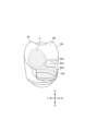
- FIG. 1 is a cross-sectional view of the internal combustion engine 10 along the axis (cylinder axis) C of the cylinder bore 12b of the cylinder block 12 of the internal combustion engine 10.
- the internal combustion engine 10 is a single cylinder engine.
- a piston 15 that reciprocates within a cylinder bore 12b of the cylinder block 12 is connected to a crank pin of a crankshaft 17 of a crankcase portion 16 by a connecting rod 18.
- a combustion chamber 20 is formed between the top surface 15a of the piston 15, which is slidably fitted into the cylinder bore 12b of the cylinder block 12, and the combustion chamber ceiling surface 14a of the cylinder head 14, which the top surface 15a faces. Ru.
- the internal combustion engine 10 employs an SOHC type two-valve system, and the cylinder head 14 is provided with a valve mechanism 22.
- a cylinder head cover 24 is placed over the cylinder head 14 so as to cover the valve mechanism 22.
- an endless cam chain (not shown) is provided on one side of the crankcase portion 16, the cylinder block 12, and the cylinder head 14 in the crankshaft direction.
- the camshaft 26 is installed between the camshaft 26 and the crankshaft 17 through the cam chain chamber, and the camshaft 26 rotates in synchronization with the crankshaft 17 at a rotation speed of 1/2.
- a spark plug is inserted into the combustion chamber 20 from the side opposite to the cam chain chamber (the other side in the crankshaft direction) in the cylinder head 14.
- the spark plug facing the combustion chamber 20 is located on the front side of the page, and the cam chain chamber is located on the back side of the page.
- an intake port 32 and an exhaust port 34 are formed to curve and extend vertically away from each other from an intake valve port 28 and an exhaust valve port 30 that are open to the combustion chamber ceiling surface 14a. Note that, as described above, a two-valve system is adopted, and the cylinder head 14 is defined with a single intake port 32 and a single exhaust port 34.
- the upstream end of the intake port 32 opens toward the upper side of the cylinder head 14 and is connected to the inlet pipe 36 to form a continuous intake passage 38.
- a throttle body 40 is connected to the upstream side of the inlet pipe 36.
- Ru is connected to the upstream side of the inlet pipe 36.
- a downstream end of the exhaust port 34 opens toward the bottom of the cylinder head 14 and is connected to an exhaust pipe 42.
- An exhaust purification device and a muffling device may be provided downstream of the exhaust pipe 42.
- a cylindrical intake valve guide 44 is integrally fitted into the curved outer wall portion 32a of the intake port 32 in the cylinder head 14.
- An intake valve 46 slidably supported by an intake valve guide 44 opens and closes an intake valve port 28 of the intake port 32 facing the combustion chamber 20.
- an exhaust valve 50 that is slidably supported by an exhaust valve guide 48 that is integrally fitted to the curved outer wall portion 34a of the exhaust port 34 in the cylinder head 14 has an exhaust valve port that faces the combustion chamber 20 of the exhaust port 34. Open and close 30.
- the intake valve 46 and the exhaust valve 50 are urged upward by a valve spring so that their umbrella parts 46a and 50a close the intake valve port 28 and the exhaust valve port 30 facing the combustion chamber 20.
- the stem ends 46b and 50b of the intake valve 46 and exhaust valve 50 are pushed down by the intake rocker arm 56 and exhaust rocker arm 58, which swing in contact with the intake cam and exhaust cam of the camshaft 26, and the intake valve 46 and the exhaust valve 50 are pushed down at a predetermined timing.
- the exhaust valve 50 opens, and the intake port 32 and the combustion chamber 20 communicate with each other, and the exhaust port 34 and the combustion chamber 20 communicate with each other, so that intake and exhaust are performed at predetermined timings.
- An inlet pipe 36 is connected to the upstream end of the intake port 32 of the internal combustion engine 10 via an insulator 60 to form a continuous intake passage 38, and a throttle body 40 is connected to the upstream side of the inlet pipe 36. be done.
- the throttle body 40 has an intake passage 40a having a substantially circular cross section and forming a part of the intake passage 38 connected to the combustion chamber 20 of the internal combustion engine 10, and the upstream side of the intake passage 40a is connected to an air cleaner device (not shown).
- the throttle body 40 is rotatably supported within the throttle body 40 by a throttle valve shaft 40b that is perpendicular to the flow direction of intake air in the intake passage 40a, that is, perpendicular to the center axis of the intake passage 40a.
- the intake passage 40a is provided with a throttle valve 40c that can variably control the flow passage area of the intake passage 40a and open/close the intake passage 40a.
- the throttle valve 40c is of a butterfly type and includes a throttle valve shaft 40b and a disc-shaped valve body 40d that is fixed to the throttle valve shaft 40b and rotates integrally with the throttle valve shaft 40b.
- the throttle valve 40c can be rotated clockwise in the valve opening direction in FIG. 1 by the driver's operation, and a return spring (not shown) causes the valve body 40d to have its edge inside the intake passage 40a. It is biased counterclockwise in the valve closing direction so that it is in the fully closed position where it contacts the wall surface.
- the throttle valve 40c is controlled, for example, to open the intake passage 40a to a predetermined small opening degree in a low-load operating state, and to fully open the intake passage 40a in a high-load operating state.
- the intake structure S0 provides a tumble vortex flow, that is, a vertical rotation, of the fuel/air mixture in the combustion chamber 20 in order to obtain more preferable combustion of the fuel or mixture in the combustion chamber 20.
- the intake structure S0 includes a partition 62 provided in the intake passage 38 so as to divide the intake passage 38 into a plurality of parts in the direction of the cylinder axis C. That is, the intake passage 38 is divided along the intake flow direction by a partition 62 that extends from the inlet pipe 36 to the intake port 32, and the intake passage 38 is configured to generate a tumble flow within the combustion chamber 20. It is partitioned into a tumble passage 64 and a main passage 66 excluding the tumble passage 64.
- the tumble passage 64 corresponds to a first intake passage
- the main passage 66 corresponds to a second intake passage. Note that the tumble passage 64 may also be referred to as a sub-passage.
- the partition portion 62 extending in a plate shape in the intake flow direction substantially extends substantially parallel to the axis extending in the flow direction so as to substantially bisect the downstream side of the intake passage 38 in the vertical direction. It is set up like this.
- the cross-sectional area of the tumble passage 64 is smaller than the cross-sectional area of the main passage 66.
- the partition portion 62 may be provided such that the cross-sectional area of the tumble passage 64 is larger than the cross-sectional area of the main passage 66, or they may be made substantially the same.
- the lower part of the intake passage 38 partitioned by the partition part 62 is the tumble passage 64, and the upper part is the main passage 66, but in this specification they are not limited to their vertical arrangement.
- "upper” and “lower” with respect to the intake passage 38, etc. refer to the direction from the crankshaft 17 side to the cylinder head 14 or cylinder head cover 24 side in the direction of the cylinder axis C. ” direction, and the direction opposite to this “up” direction, that is, the direction from the cylinder head 14 side to the crankshaft 17 side, is called the “down” or “down” direction, and is the absolute “up” and “down” direction in space. ” does not mean.
- This "up” or “up” direction corresponds to the first direction
- the "down” or “down” direction corresponds to the second direction.
- an intake control valve may be further provided upstream of the partition portion 62 and downstream of the throttle valve 40c.
- This intake control valve may be provided to variably control the flow area of the main passage 66, for example.
- the intake control valve may also be referred to as a tumble valve, tumble control valve, or TCV, and is controlled to, for example, fully close the main passage 66 in a low-load operating state and fully open the main passage 66 in a high-load operating state.
- Ru The throttle valve 40c is electronically controlled as described below, but is not limited to being electronically controlled. For example, it may be a valve that is mechanically controlled by a throttle cable, and this may be a valve that is controlled mechanically by a throttle cable. The same applies when a valve is provided.
- the internal combustion engine 10 is provided with fuel injection valves 68 and 70.
- One fuel injection valve (hereinafter referred to as a first fuel injection valve) 68 is provided upstream of the upstream end 62u of the partition portion 62, and is located in the intake passage 38 upstream of the upstream end 62u. It is provided to inject fuel into the area.
- the other fuel injection valve (hereinafter referred to as a second fuel injection valve) 70 is provided to inject fuel into the intake port 32.
- the second fuel injection valve 70 is provided so as to face the main passage 66, and is provided in the inlet pipe 36 here. In this way, the second fuel injection valve 70 is provided to inject fuel from the main passage 66 side and supply the fuel to the combustion chamber 20 via the intake port 32.
- the second fuel injection valve 70 is attached to the upper wall of the member defining the intake passage 38. Note that the present disclosure does not limit the number of fuel injection valves to two, and may be one, for example. In this case, for example, only the second fuel injection valve 70 can be provided.
- An ECU (electronic control unit) 72 that controls the internal combustion engine 10 has a configuration as a so-called computer, and includes an intake control section 74 and a fuel injection control section 76. That is, the ECU 72 includes a processor (eg, CPU) and memory (eg, ROM and RAM). The ECU 72 analyzes the operating state of the internal combustion engine 10 based on outputs from various sensors such as an engine speed sensor and an engine load sensor, and controls the operation of the throttle valve 40c using the intake control section 74. Furthermore, the ECU 72 controls each operation of the fuel injection valves 68 and 70 using a fuel injection control section 76 based on the analyzed operating state of the internal combustion engine 10. Note that the ECU 72 stores programs and various data for these controls.
- a processor eg, CPU
- memory eg, ROM and RAM
- the ECU 72 analyzes the operating state of the internal combustion engine 10 based on outputs from various sensors such as an engine speed sensor and an engine load sensor, and controls the operation of the throttle valve 40
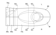
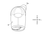
- FIGS. 2 to 9 a three-dimensional model M of the downstream side of the intake passage 38 is shown in FIGS. 2 to 9.
- the three-dimensional model M includes an intake port 32 from the downstream end of the inlet pipe 36, and terminates at the intake valve port 28 on the downstream side.
- the three-dimensional model M is a model of the downstream end of the intake passage 38, so the outer surface 80 of the three-dimensional model M includes the inner surface 36s of the inlet pipe 36, which is a member that defines the downstream side of the intake passage 38, and the insulator. 60 and an inner wall surface 14s of the cylinder head 14, a portion corresponds to a surface 62s of the partition portion 62, and a portion corresponds to a surface 90s of a deflection portion 90, which will be described later.
- the symbol “U” is used for the upper side
- the symbol “D” is used for the lower side
- the symbol “R” is used for the right side when looking from the upstream side to the downstream side in the intake flow direction
- the suffix "L” is used on the left side.
- the width of the partition portion 62 in the left-right direction (LR direction) intersecting the cylinder axis C, that is, the width in the width direction, is on the upstream side of the partition portion 62 on the downstream side. It has a deflection section 90 that is narrower than the end (upstream end) 62u.
- the deflection portion 90 extends from one side of the valve axis of the intake valve 46 to the other side when facing the intake valve 46 in the direction in which intake air flows through the intake passage 38 from the upstream side to the downstream side, that is, in the intake flow direction.
- This is the narrow portion of the partition portion 62 in the width direction which can be defined as a direction. As shown in FIG.
- the width W2 of the downstream end portion 64d is clearly narrow. Since the partition portion 62 is formed so as to partition the tumble passage 64 in the intake passage 38, the deflection portion 90 with respect to the width W2 portion is relatively narrow.
- the deflecting portion 90 is biased in one direction in the left-right direction, that is, in the width direction.
- the downstream end portion 64d of the tumble passage 64 is partitioned so as to be biased toward the right R side. Therefore, the downstream biased portion 90 of the partition portion 62 that at least partially defines the biased downstream end portion 64d of the tumble passage 64 is biased to the right R side here. Therefore, in FIG. 1, the cylinder axis C extends parallel to the plane of the paper, and the width direction extends substantially perpendicular to the plane of the paper, so the deflection part 90 extending downstream of the partition part 62 does not appear. Therefore, it is shown as a double-dashed line instead of a solid line. Therefore, the merging portion 65 between the main passage 66 and the tumble passage 64 is biased toward the right R side.
- the mounting portion 70s of the second fuel injection valve 70 is positioned on the left L side of the intake passage 38, as is clear from FIGS. 6 and 7. In this way, the second fuel injection valve 70 is provided at a position that is biased in the direction opposite to the direction in which the deflection portion 90 is biased. In this way, the second fuel injection valve 70 is provided so as to be able to inject fuel in a direction different from the direction in which the deflection portion 90 is biased, and more preferably in the opposite direction. Note that the second fuel injection valve 70 is provided on the upper side, that is, on the main passage 66 side, and injects fuel from the main passage 66 side.
- FIG. 10 which is a perspective view of the three-dimensional model M shown in FIG. 5
- the sprayed fuel F injected from the second fuel injection valve 70 provided at a position biased toward the left L side is schematically shown.
- FIG. 11 shows a perspective view of the three-dimensional model M, which schematically shows the sprayed fuel F injected from the fuel injection valve in the same way as shown in FIG. 10.
- FIG. 12 shows a cross-sectional view of the three-dimensional model M along the intake flow direction, schematically showing the atomized fuel F injected from the fuel injection valve in the same way as shown in FIG. From FIGS.
- the fuel F injected from the second fuel injection valve 70 is not blocked by the partition part 62, and at least a part of it, especially at least a majority of it here, more preferably all of it, It can be seen that the air first flows through the main passage 66, then flows to the confluence 65 between the main passage 66 and the tumble passage 64, and then directly reaches the intake valve port 28 and is introduced into the combustion chamber 20.
- the arrangement of the second fuel injection valve 70, the shape of the partition portion 62 including the deflection portion 90, etc. are designed to enable such fuel injection.
- the partition body 92 of the partition 62 terminates downstream thereof to allow the main passage 66 and tumble passage 64 to merge, and also preferably extends along the surface 90s of the deviation part 90.
- the partition main body part 92 and deflection part 90 of the partition part 62 are designed so that the fuel F injected from the second fuel injection valve 70 reaches the intake valve port 28 without touching the fuel injector 70 (for example, see FIG. 11). ).
- FIGS. 13A to 14C cross-sectional views of the three-dimensional model M including the injected fuel F in FIG. 10 are shown in FIGS. 13A to 14C.
- FIG. 13A is a cross-sectional view of the three-dimensional model M at a position along the line SA-SA in FIG. 2
- FIG. 13B is a cross-sectional view of the three-dimensional model M at a position along the line SB-SB in FIG. 13C is a cross-sectional view of the three-dimensional model M at a position along line SC-SC in FIG. 2.
- 14A to 14C are perspective views of the 3D model M in FIGS. 13A to 13C
- the 3D model in FIG. 14A corresponds to the 3D model in FIG. 13A
- the 3D model in FIG. 14B corresponds to the 3D model in FIG. 13B.
- the three-dimensional model in FIG. 14C corresponds to the three-dimensional model in FIG. 13C.
- FIGS. 13A and 14A At the cutting locations in FIGS. 13A and 14A, the tumble passage 64 and the main passage 66 are completely separated. At the position of the SA-SA line in FIG. A partition main body portion 92 extending to the upstream side extends. In addition, in FIGS. 13A and 14A, the surface 62s of the partition portion 62 and the portions corresponding to the surface 92s of the partition main body portion 92 are given the same reference numerals.
- the tumble passage 64 and the main passage 66 are partially connected. Further, in the cut planes of FIGS. 13B and 14B, the surface 62s of the partition portion 62 extends in the width direction and also extends in the vertical direction, and is biased to the right side. From this, at the position of the SB-SB line in FIG. It can be seen that the intake port 32 extends to the left from the right side of the inner wall surface 14s of the cylinder head 14 to the extent that the intake port 32 is not separated from the intake port 32.
- the tumble passage 64 and the main passage 66 are formed into sections such that the main passage 66 and the tumble passage 64 communicate with each other in the region where the deflection portion 90 extends in the intake flow direction.
- the deflection section 90 connected to the partition main body 92 extends downstream of the partition main body 92 so that a part of the partition main body 92 of the partition 62 extends in the flow direction. It is formed to extend to the side.
- the surface 62s of the partition portion 62 and the portions thereof corresponding to the surface 90s of the deflection portion 90 are labeled with those symbols, and this is the same in FIGS. 13C and 14C. .
- the amount of leftward protrusion of the deflection portion 90 from the inner wall surface 14 of the cylinder head 14 is reduced compared to the cut locations in FIGS. 13B and 14B.
- the deflection portion 90 is formed so as to become narrower toward the downstream side in the intake flow direction.
- the degree of communication between the main passage 66 and the tumble passage 64 is increased at the cut locations shown in FIGS. 13C and 14C than at the cut locations shown in FIGS. 13B and 14B. That is, the amount of connection between the tumble passage 64 and the main passage 66 at the cutting positions in FIGS. 13C and 14C is greater than the amount of connection between them at the cutting positions in FIGS.
- the tumble passage 64 and the main passage 66 are partitioned so that the main passage 66 extends downward to the side or side of the deviation part 90 in the region where the deviation part 90 extends in the intake flow direction. It is formed.
- This downward expansion of the main passage 66 is performed in a direction opposite to the direction in which the deflection section 90 is biased, and here, it is performed on the left L side of the deflection section 90. Note that this downward expansion of the main passage 66 and the resulting fusion of the main passage 66 and the tumble passage 64 are more pronounced on the downstream side of the deflection portion 90.
- the second fuel injection valve 70 which is provided to inject the fuel F from the main passage 66 side toward the combustion chamber 20, It is designed to inject fuel in the opposite direction. Therefore, the partition portion 62, particularly its deflection portion 90, can be extended further downstream in the intake flow direction.
- the tumble passage 64 is formed into sections so as to be biased on the downstream side in the direction in which the deflection portion 90 is biased. Therefore, the deflection portion 90 of the partition portion 62 that extends further downstream in the intake flow direction can provide stronger directivity to the intake air from the tumble passage 64.
- the partition part 62 completely partitions the main passage 66 and the tumble passage 64 with the partition main part 92 on the upstream side, and has the deflection part 90 on the downstream side thereof to separate the main passage 66 and the tumble passage. It is designed to realize the connection with the passage 64 while characterizing the flow from the tumble passage 64 further downstream.
- the second fuel injection valve 70 is disposed biased to the opposite side to the biased direction of the biased portion 90, and here is disposed on the opposite side in the width direction, and injects fuel in a direction different from the biased portion 90.
- the fuel can be introduced into the combustion chamber 20 almost directly through the intake valve port 28. In other words, it is possible to ensure a good supply of fuel to the combustion chamber.
- the deflection portion 90 which is the downstream portion of the partition portion 62, can be extended further downstream. Therefore, stronger directivity can be given to the flow from the tumble passage 64.
- This directivity is oriented between the intake valve port 28 and the umbrella portion 46a of the intake valve 46 when the valve is open so as to form a stronger tumble flow in the combustion chamber 20, so that the intake air from the tumble passage 64 is A tumble flow can be suitably formed by the combustion chamber 20.
- the tumble passage 64 communicates with the main passage 66 at the downstream edge of the partition part 62, that is, downstream of the downstream edge 90d of the deflection part 90, so as to form a single intake passage connected to the combustion chamber 20.
- the tumble passage 64 and the main passage 66 are divided into sections. This allows intake air from the tumble passage 64 to be introduced into the combustion chamber 20 along with intake air from the main passage 66, and intake air from the single intake port 32, which is a single intake passage, to introduce fuel into the combustion chamber 20. It becomes possible to create a supply and a tumble flow formation. Note that this configuration can suppress an increase in the number of parts and is also excellent in terms of cost.
- the intake structure S0 of the internal combustion engine 10 having the above configuration has excellent functions and effects, but in addition to this configuration, the present invention also has a configuration aimed at further strengthening the tumble flow.
- the internal combustion engine 110 according to the first embodiment of the invention, particularly its intake structure S, will be described below.
- the intake structure S of the internal combustion engine 110 generally has the above-described configuration of the intake structure S0 of the internal combustion engine 10, and has additional configurations or features.
- the same reference numerals as those already used will be used for components that correspond to or correspond to those already described, and further redundant explanation will be omitted.
- the internal combustion engine 110 is a single cylinder engine, the internal combustion engine to which the present invention is applied is not limited to a single cylinder engine, and may be a multi-cylinder engine.
- the internal combustion engine 110 does not include the first fuel injection valve 68, but includes a fuel injection valve 70a corresponding to the second fuel injection valve.
- the internal combustion engine 110 may include the first fuel injection valve 68.
- the internal combustion engine 110 includes the above-mentioned tumble valve 94c so that the main passage 66 partitioned by the partition portion 62 can be opened and closed.
- a tumble valve body 94 is connected to the upstream end of the inlet pipe 36 via an insulator 95.
- the tumble valve body 94 has an intake passage 94a having a substantially circular cross section and forming a part of the intake passage 38, and the aforementioned throttle body 40 is connected to the upstream end of the intake passage 94a.
- the tumble valve body 94 is rotatably supported within the tumble valve body 94 by a valve shaft 94b that is perpendicular to the intake flow direction of the intake passage 94a, that is, perpendicular to the center axis of the intake passage 94a.
- a tumble valve 94c is provided which can variably control the flow path area of the intake path 94a and open and close the upper area of the intake path 94a in cooperation with the partition portion 62.
- the operation of the tumble valve 94c is electronically controlled here according to the operating state of the internal combustion engine 110, but is not limited thereto.
- the tumble valve 94c is controlled, for example, to fully close the main passage 66 in a low load operating state and to fully open the main passage 66 in a high load operating state.
- the tumble valve 94c is of a butterfly type and includes a valve shaft 94b and a substantially disc-shaped valve body 94d that is fixed to the valve shaft 94b and rotates integrally with the valve shaft 94b.
- the tumble valve 94c is configured to include the valve body 94d, which is a single valve member that rotates integrally with the valve shaft 94b.
- the valve shaft 94b of the tumble valve 94c is parallel to the throttle valve shaft 40b.
- the internal combustion engine 110 has a feature regarding the tumble passage 64.
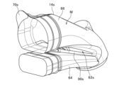
- the tumble passage 64 will be explained based on FIGS. 16 to 18.
- FIG. 16 to 18 show a three-dimensional model M1 centered on the downstream side of the intake system from the upper part of the combustion chamber 20 of the internal combustion engine 110, for example, the intake port 32.
- FIG. 16 is a plan view or top view of the three-dimensional model M1, which corresponds to the plan view (FIG. 2) of the internal combustion engine 10
- FIG. 17 is a bottom view of the three-dimensional model M1, which corresponds to the bottom view ( 4)
- FIG. 18 is a side view of the three-dimensional model M1, and corresponds to a rear view of the internal combustion engine 10 (FIG. 5).
- the intake passage 38 connected to the combustion chamber 20 is divided into a tumble passage 64, which is a first intake passage, and a second intake passage, by a partition portion 62 in the direction of the cylinder axis C. It is divided into 66 main passages.
- the main passage 66 is provided above the tumble passage 64 in the direction of the cylinder axis C.
- the tumble passage 64 In a top view from the direction of the cylinder axis C (FIG. 16), the tumble passage 64 generally overlaps the main passage 66, and the merging part 65 of the tumble passage 64 with the main passage 66 is the opening of the intake port 32, that is, the intake It is biased toward the valve port 28, and here, as already explained, it is biased to the right R side.
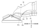
- the tumble passage 64 provided to generate a tumble flow in the combustion chamber 20 is curved away from the main passage 66 in the direction of the cylinder axis C, and is perpendicular to the cylinder axis C. At the same time, it is formed to be curved in the width direction perpendicular to the intake and exhaust direction.
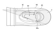
- a virtual plane IS is drawn in FIGS. 16 and 17 that includes the cylinder axis C and extends in the intake and exhaust direction.
- This virtual surface IS is a virtual surface that extends in the intake and exhaust direction, passes through the center of the intake valve port 28 and the exhaust valve port 30, and includes the cylinder axis C, and is represented as a line (center line) Lx in FIGS. 16 and 17. has been done.
- Lx center line
- the right-hand contour 64r of the tumble passage 64 is not parallel to the center line Lx, but is curved convexly to the outer right.
- the contour 64r goes from the upstream side to the downstream side in the intake flow direction, it first widens to protrude to the right outside, passes through the maximum right protrusion 64s, and extends toward the center line Lx side. That is, in the top view of FIG. 16, the tumble passage 64 is formed to curve convexly toward the same side as the side where the merging portion 65 is biased.
- the tumble passage 64 is formed to be perpendicular to the cylinder axis C and curved in the width direction, that is, the left-right direction, that is perpendicular to the intake and exhaust direction, that is, the line Lx.
- the tumble passage 64 is curved away from the main passage 66.
- the partition part 62 is provided in the middle of the intake passage 38, and is provided so that the tumble passage 64 branches from the main passage 66, and the tumble passage 64 joins the main passage 66 on the downstream side thereof.
- the tumble passage 64 curves convexly on the side opposite to the main passage 66. More specifically, the tumble passage 64 is formed to curve convexly toward the crankshaft 17 in the direction of the cylinder axis C, that is, curve convexly downward.
- a plane or line Ly is drawn that is perpendicular to the cylinder axis C and in contact with the lower contour 64t of the tumble passage 64.
- the contour 64t extends from the upstream side to the downstream side in the intake flow direction, first protruding downward, passing through the maximum lower protrusion 64u, and extending upward.
- the contour 64t touches the line Ly not at both ends but at the maximum protrusion 64u.
- the vertical width of the tumble passage 64 does not change significantly from the upstream side to the downstream side in the intake flow direction. Therefore, in the internal combustion engine 110, the tumble passage 64 is curved in the direction of the cylinder axis C in a side view (FIG.
- the tumble passage 64 is curved in the direction of the cylinder axis C. It is curved in a substantially U-shape so as to be convex to the lowest side in the direction of the cylinder axis C. Therefore, in FIG. 18, the downstream portion 64L of the tumble passage 64 is formed so as to approach the cylinder head 24 from the crankshaft 17 side in the direction of the cylinder axis C as it reaches the downstream side in the intake flow direction.
- the downstream portion 64L of the tumble passage 64 includes a portion downstream of the maximum protrusion 64u in the tumble passage 64.
- the curved shape of the contour 64t is as follows in a side view from a direction perpendicular to the cylinder axis C, that is, in FIG. The same applies to the wall surface ds of the partition portion 62 that defines the tumble passage 64. That is, in FIG. 18, the wall surface ds of the partition portion 62 defining the tumble passage 64 is curved so as to be convex toward the crankshaft 17 in the direction of the cylinder axis C.
- FIG. 16 when viewed from above in the direction of the cylinder axis C, there is a merging portion 65 on one side of a virtual plane IS that includes the cylinder axis C and extends in the intake and exhaust direction, here on the right R side. , a spark plug facing the combustion chamber 20 is arranged. In FIG. 16, the ignition part p of the spark plug is shown.
- FIG. 20 shows a three-dimensional model M2 incorporating the three-dimensional model M of the intake structure S0 of the internal combustion engine 10 of the reference example.
- the throttle valve 40c and the tumble valve 94c on the downstream side thereof are provided, although not shown, as already explained.
- the intake passage 38 is divided by the partition portion 62, and a main passage 66 is formed above the tumble passage 64. That is, in the direction of the cylinder axis C, a tumble passage 64 for generating a tumble flow in the combustion chamber 20 and a main passage 66 are provided in the intake passage 38 connected to the combustion chamber 20 so as to overlap with each other.
- the tumble passage 64 is formed to be curved in a width direction that is perpendicular to the cylinder axis C and perpendicular to the intake and exhaust direction.
- the intake air from the tumble passage 64 is on the right side of the intake air from the main passage 66. It flows into the combustion chamber 20 from the merging portion 65. This reduces the degree to which the intake air from the tumble passage 64 is interfered with by the intake air from the main passage 66, making it possible to suitably form a tumble flow in the combustion chamber.
- the tumble passage 64 is curved away from the main passage 66 in the direction of the cylinder axis C. Therefore, the intake air from the tumble passage 64 can smoothly flow into the combustion chamber 20 so as to form a tumble flow. Therefore, a stronger tumble flow can be generated in the combustion chamber.
- the merging portion 65 is biased with respect to the opening 28 of the intake port 32 when viewed from above in FIG. Therefore, during the intake stroke, the intake valve 46 opens and the flow of intake air flowing into the combustion chamber can be set at an angle corresponding to its bias. Further, the tumble passage 64 is formed to curve convexly toward the same side as the side where the merging portion 65 is biased. Therefore, the degree to which the intake air from the tumble passage 64 interferes with the intake air from the main passage 66 can be further reduced, making it possible to suitably form a tumble flow in the combustion chamber.
- the tumble passage 64 is formed to curve convexly toward the crankshaft 17 in the direction of the cylinder axis C. Therefore, it is possible to actively encourage the intake air from the tumble passage 64 to separate from the wall portion forming the tumble passage 64 at the confluence portion 65, particularly from the wall portion 64w defining the lower contour 64t of the tumble passage 64.
- the flow of intake air from the tumble passage 64 at this time is shown by arrow A3 in FIG. This makes it possible to increase the flow rate of intake air from the tumble passage 64 and generate a stronger tumble flow.
- the tumble passage 64 is formed to curve convexly toward the crankshaft 17 in the direction of the cylinder axis C, the position of the merging portion 65 is as shown in FIG. The position will be above the part 46s where it hits. By adjusting the position of this merging portion 65 based on experiments or the like, the direction of the intake air from the tumble passage 64 can be optimized, and the generation of the tumble flow can be further promoted.
- the downstream portion 64L of the tumble passage 64 is formed so that the further downstream in the intake flow direction, the closer it gets from the crankshaft 17 side to the cylinder head 24 side in the direction of the cylinder axis C. . Therefore, it is possible to more actively encourage the intake air from the tumble passage 64 to separate from the wall portion 64w defining the lower contour 64t of the tumble passage 64.
- the wall surface ds of the partition portion 62 defining the tumble passage 64 is curved so as to be convex toward the crankshaft 17 in the direction of the cylinder axis C. Therefore, the vertical widths of the tumble passages can be made approximately the same, and the intake air from the tumble passage 64 can be directed to generate more tumble flow.
- the wall surface ds is a wall surface on the main passage 66 side that defines the tumble passage 64.
- the merging portion 65 and the spark plug facing the combustion chamber 20 are arranged on one side of a virtual plane IS that includes the cylinder axis C and extends in the intake and exhaust direction, here on the right R side. ing. Therefore, the intake air from the tumble passage 64 makes it possible to more quickly carry the spark from the ignition plug to the center of the combustion chamber, thereby making it possible to further increase the flame propagation speed.
- the internal combustion engine of the second embodiment has the features of the internal combustion engine 110 of the first embodiment, such as the above configuration of the tumble passage 64, but has additional features with respect to the configuration of the main passage 66 compared to the internal combustion engine 110. Its characteristics will be explained based on FIG. 21.
- FIG. 21 shows a three-dimensional model M3 having an intake structure S1 of an internal combustion engine according to the second embodiment.
- a throttle valve 40c and a tumble valve 94c (not shown) are provided on the upstream side of the tumble passage 64 and the main passage 66, and the throttle valve 40c is fully opened and the tumble valve 94c is fully closed. There is.
- the downstream wall surface us of the partition portion 62 that partitions the main passage 66 is This is a downstream wall surface that defines the tumble passage 64 side of 66, and has a curved shape corresponding to the curved shape of the downstream portion 64L of the tumble passage 64.
- the curved shape of the downstream wall surface us is similar to or close to, preferably the same as, the curved shape of the downstream portion 64L.
- the downstream portion 64L of the tumble passage 64 approaches the cylinder head 24 from the crankshaft 17 side in the direction of the cylinder axis C as it reaches the downstream side in the intake flow direction. is formed.
- the downstream wall surface us of the partition portion 62 that defines the main passage 66 has this upwardly curved shape. Since the downstream wall surface us has this curved shape, the downstream wall surface us has a downwardly convex curved shape or a curved shape close to it.
- the downstream wall surface us of the partition portion 62 that partitions and forms the main passage 66 has the above-described configuration, for example, when the tumble valve 94c is in an operating state where it is closed, the intake air of the main passage 66 (see arrow A4) is us and can jump towards the combustion chamber 20 and is directed to smoothly merge with the intake air from the tumble passage 64 (see arrow A5). This makes it possible to promote the generation of a stronger tumble flow.
- Example 2 A computer simulation was performed on the intake structure S of the internal combustion engine according to the first embodiment. As a comparative example, a computer simulation was also performed for the intake structure S0 of an internal combustion engine as a reference example. In the computer simulation, the throttle valve 40c was fully opened and the tumble valve 94c was fully closed.
- FIGS. 22 to 24 the results of the first computer simulation are shown in FIGS. 22 to 24.
- the flow of intake air from the intake port 32 side to the combustion chamber 20 when looking at the combustion chamber 20 side from a direction perpendicular to the cylinder axis C was calculated.
- the intake air flows are shown so that the faster the flow rate, the darker the intake air flows. Note that 360° of the crank angle (deg) corresponds to the top dead center.
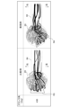
- FIGS. 25 and 26 the results of the second computer simulation are shown in FIGS. 25 and 26.
- curvature of the tumble passage 64 in the width direction perpendicular to the cylinder axis C and perpendicular to the intake/exhaust direction, that is, curvature to the right (see FIGS. 16 and 17) In order to verify the effect, the flow of intake air from the intake port 32 side to the combustion chamber 20 when looking at the combustion chamber 20 side from above in the direction of the cylinder axis C was calculated.
- FIGS. 25 and 26 the intake air flow is shown so that the faster the intake air flow, the darker the line. Note that 360° of the crank angle (deg) corresponds to the top dead center.
- the fast intake air from the intake tumble passage 64 flows into the combustion chamber 20 from the right side at an angle.
- the inflow path indicated by the black line in the comparative example is generally in the intake/exhaust direction (see direction mark R3), but the inflow path indicated by the black line in the example is inclined with respect to the intake/exhaust direction. The direction was angled from the right side to the left side (see direction mark R4).
- the curvature of the tumble passage 64 in the width direction makes it possible to angle the flow into the cylinder during the intake stroke, thereby tilting the rotation axis of the positive tumble flow. It can be seen that the intake air from the tumble passage 64 can be caused to flow into the combustion chamber 20 from the right side. This is suitable for promoting flame propagation from the spark plug on the right side where the tumble passage 64 is biased.
- Figures 27 to 29 show the results of five simulations.
- Three of the five simulations are simulations using a model having the configuration of the internal combustion engine 110 of the first embodiment, and assuming the same curvature of the tumble passage 64 in the direction of the cylinder axis C (see FIG. 18), The degree of curvature of the tumble passage 64 to the right was varied.
- the results are shown in FIGS. 27 to 29 as plots P1 to P3. That is, for example, the plots P1 in FIGS. 27 to 29 are obtained by the same simulation.
- the results obtained by simulation using a model having the configuration of the internal combustion engine 10 of the reference example are shown in broken lines in FIGS.
- the swirl ratio is small and the tumble ratio is large.
- the axis of rotation of the tumble flow is preferably inclined to the right side where the spark plug is provided, and the more the axis of rotation of the tumble flow is inclined to the right side, the more the vertical axis in FIG. Axial tilt increases.
- the tumble passage 64 is biased to the right and curved, but it may be biased and curved to the left.
- the merging portion 65 and the spark plug are preferably provided on the left side of the virtual surface IS.
- the intake structures S and S1 of the internal combustion engine of the first and second embodiments have the characteristics of the intake structure S0 of the reference example, such as the deflection portion 90, they may not have this deflection portion. It is possible.
- the tumble passages 64 of the intake structures S and S1 may be formed to be completely independent from the main passage 66 up to the merging portion 65 with the main passage 66.
Landscapes
- Engineering & Computer Science (AREA)
- Chemical & Material Sciences (AREA)
- Combustion & Propulsion (AREA)
- Mechanical Engineering (AREA)
- General Engineering & Computer Science (AREA)
- Cylinder Crankcases Of Internal Combustion Engines (AREA)
Abstract
La présente divulgation vise à fournir une configuration qui permet de générer un écoulement tourbillonnaire plus fort dans une chambre de combustion dans un moteur à combustion interne dans lequel un passage pour un écoulement tourbillonnaire et un autre passage sont disposés de manière à se chevaucher dans un passage d'admission dans la direction de la ligne d'axe de cylindre. Dans une structure d'admission (S) d'un moteur à combustion interne selon un mode de réalisation, un premier passage d'admission (64) est formé de manière à s'incurver à l'opposé d'un second passage d'admission (66) dans la direction d'une ligne d'axe de cylindre (C), et de manière à s'incurver dans une direction de largeur qui est orthogonale à la ligne d'axe de cylindre (C) et est orthogonale à une direction d'admission/d'échappement.
Priority Applications (1)
| Application Number | Priority Date | Filing Date | Title |
|---|---|---|---|
| PCT/JP2022/016655 WO2023188310A1 (fr) | 2022-03-31 | 2022-03-31 | Structure d'admission de moteur à combustion interne |
Applications Claiming Priority (1)
| Application Number | Priority Date | Filing Date | Title |
|---|---|---|---|
| PCT/JP2022/016655 WO2023188310A1 (fr) | 2022-03-31 | 2022-03-31 | Structure d'admission de moteur à combustion interne |
Publications (1)
| Publication Number | Publication Date |
|---|---|
| WO2023188310A1 true WO2023188310A1 (fr) | 2023-10-05 |
Family
ID=88199919
Family Applications (1)
| Application Number | Title | Priority Date | Filing Date |
|---|---|---|---|
| PCT/JP2022/016655 WO2023188310A1 (fr) | 2022-03-31 | 2022-03-31 | Structure d'admission de moteur à combustion interne |
Country Status (1)
| Country | Link |
|---|---|
| WO (1) | WO2023188310A1 (fr) |
Citations (4)
| Publication number | Priority date | Publication date | Assignee | Title |
|---|---|---|---|---|
| DE19740229A1 (de) * | 1997-09-12 | 1999-03-18 | Bayerische Motoren Werke Ag | Brennkraftmaschinen-Zylinderkopf mit Ansaugkanal und Zusatzluftkanal |
| JP2005351235A (ja) * | 2004-06-14 | 2005-12-22 | Yamaha Motor Co Ltd | エンジンの吸気装置 |
| WO2019009061A1 (fr) * | 2017-07-05 | 2019-01-10 | 本田技研工業株式会社 | Structure d'admission d'air destinée à un moteur à combustion interne |
| JP2019157804A (ja) * | 2018-03-15 | 2019-09-19 | 本田技研工業株式会社 | 内燃機関の吸気通路 |
-
2022
- 2022-03-31 WO PCT/JP2022/016655 patent/WO2023188310A1/fr active Search and Examination
Patent Citations (4)
| Publication number | Priority date | Publication date | Assignee | Title |
|---|---|---|---|---|
| DE19740229A1 (de) * | 1997-09-12 | 1999-03-18 | Bayerische Motoren Werke Ag | Brennkraftmaschinen-Zylinderkopf mit Ansaugkanal und Zusatzluftkanal |
| JP2005351235A (ja) * | 2004-06-14 | 2005-12-22 | Yamaha Motor Co Ltd | エンジンの吸気装置 |
| WO2019009061A1 (fr) * | 2017-07-05 | 2019-01-10 | 本田技研工業株式会社 | Structure d'admission d'air destinée à un moteur à combustion interne |
| JP2019157804A (ja) * | 2018-03-15 | 2019-09-19 | 本田技研工業株式会社 | 内燃機関の吸気通路 |
Similar Documents
| Publication | Publication Date | Title |
|---|---|---|
| US7802555B2 (en) | Intake control device for an engine | |
| JP3494284B2 (ja) | 4ストロークサイクル内燃機関の吸気ポート構造 | |
| EP0769610B1 (fr) | Système d'injection de carburant d'un moteur à combustion pauvre | |
| WO2023188310A1 (fr) | Structure d'admission de moteur à combustion interne | |
| JPH07119592A (ja) | 燃料噴射式2バルブエンジン | |
| JP7403708B2 (ja) | 内燃機関の吸気構造 | |
| JP3402640B2 (ja) | エンジンの吸気制御装置 | |
| US7137380B1 (en) | Internal combustion engine with ignition plug and vehicle provided with the same | |
| WO2022210120A1 (fr) | Structure d'admission d'air pour moteur à combustion interne | |
| WO2024070901A1 (fr) | Structure d'admission pour moteur à combustion interne | |
| JP7403707B2 (ja) | 内燃機関の吸気構造 | |
| JP2003343351A (ja) | 内燃機関のピストン | |
| JP7411142B2 (ja) | 内燃機関 | |
| WO2023053346A1 (fr) | Dispositif d'admission d'air pour moteur à combustion interne | |
| WO2023188249A1 (fr) | Structure d'admission d'air pour moteur à combustion interne | |
| JP3601259B2 (ja) | 筒内直接噴射式エンジン | |
| JP3840822B2 (ja) | 直接噴射式火花点火機関 | |
| JP3506769B2 (ja) | エンジンの吸気制御装置 | |
| JP3612875B2 (ja) | 筒内噴射型エンジン | |
| JP6958430B2 (ja) | 内燃機関 | |
| JP6824218B2 (ja) | 内燃機関の副燃焼室 | |
| JPH04124426A (ja) | エンジンの燃焼室構造 | |
| JPH07189713A (ja) | エンジンの吸気装置 | |
| JP3727357B2 (ja) | 4サイクルエンジンの燃料噴射制御装置 | |
| JP3447810B2 (ja) | 4サイクルエンジンの吸気装置 |
Legal Events
| Date | Code | Title | Description |
|---|---|---|---|
| 121 | Ep: the epo has been informed by wipo that ep was designated in this application |
Ref document number: 22935452 Country of ref document: EP Kind code of ref document: A1 |
|
| DPE1 | Request for preliminary examination filed after expiration of 19th month from priority date (pct application filed from 20040101) |