WO2023188310A1 - Intake structure of internal combustion engine - Google Patents
Intake structure of internal combustion engine Download PDFInfo
- Publication number
- WO2023188310A1 WO2023188310A1 PCT/JP2022/016655 JP2022016655W WO2023188310A1 WO 2023188310 A1 WO2023188310 A1 WO 2023188310A1 JP 2022016655 W JP2022016655 W JP 2022016655W WO 2023188310 A1 WO2023188310 A1 WO 2023188310A1
- Authority
- WO
- WIPO (PCT)
- Prior art keywords
- intake
- passage
- tumble
- internal combustion
- combustion engine
- Prior art date
Links
- 238000002485 combustion reaction Methods 0.000 title claims abstract description 159
- 238000013459 approach Methods 0.000 claims description 4
- 239000000446 fuel Substances 0.000 description 67
- 238000005192 partition Methods 0.000 description 59
- 238000002347 injection Methods 0.000 description 41
- 239000007924 injection Substances 0.000 description 41
- 238000011144 upstream manufacturing Methods 0.000 description 27
- 238000005094 computer simulation Methods 0.000 description 13
- 238000004088 simulation Methods 0.000 description 6
- 230000000052 comparative effect Effects 0.000 description 5
- 238000010586 diagram Methods 0.000 description 4
- 230000000694 effects Effects 0.000 description 4
- 239000012212 insulator Substances 0.000 description 4
- 230000015572 biosynthetic process Effects 0.000 description 2
- 238000002474 experimental method Methods 0.000 description 2
- 230000006870 function Effects 0.000 description 2
- 239000000203 mixture Substances 0.000 description 2
- 238000000926 separation method Methods 0.000 description 2
- 230000004927 fusion Effects 0.000 description 1
- 238000012986 modification Methods 0.000 description 1
- 230000004048 modification Effects 0.000 description 1
- 230000001737 promoting effect Effects 0.000 description 1
- 238000000746 purification Methods 0.000 description 1
- 238000005728 strengthening Methods 0.000 description 1
- 238000006467 substitution reaction Methods 0.000 description 1
Images


Classifications
-
- F—MECHANICAL ENGINEERING; LIGHTING; HEATING; WEAPONS; BLASTING
- F02—COMBUSTION ENGINES; HOT-GAS OR COMBUSTION-PRODUCT ENGINE PLANTS
- F02B—INTERNAL-COMBUSTION PISTON ENGINES; COMBUSTION ENGINES IN GENERAL
- F02B31/00—Modifying induction systems for imparting a rotation to the charge in the cylinder
- F02B31/04—Modifying induction systems for imparting a rotation to the charge in the cylinder by means within the induction channel, e.g. deflectors
-
- Y—GENERAL TAGGING OF NEW TECHNOLOGICAL DEVELOPMENTS; GENERAL TAGGING OF CROSS-SECTIONAL TECHNOLOGIES SPANNING OVER SEVERAL SECTIONS OF THE IPC; TECHNICAL SUBJECTS COVERED BY FORMER USPC CROSS-REFERENCE ART COLLECTIONS [XRACs] AND DIGESTS
- Y02—TECHNOLOGIES OR APPLICATIONS FOR MITIGATION OR ADAPTATION AGAINST CLIMATE CHANGE
- Y02T—CLIMATE CHANGE MITIGATION TECHNOLOGIES RELATED TO TRANSPORTATION
- Y02T10/00—Road transport of goods or passengers
- Y02T10/10—Internal combustion engine [ICE] based vehicles
- Y02T10/12—Improving ICE efficiencies
Definitions
- the present invention relates to an intake structure for an internal combustion engine in which an intake passage includes a tumble diversion passage and other passages.
- a tumble valve is provided downstream of the throttle valve, and a partition plate portion that is a partition portion is provided downstream of the tumble valve from the inlet pipe to the intake port.
- This partition plate section partitions the intake passage into an upper and lower lower sub-passage and an upper main passage.
- the lower sub-passage serves as a tumble passage, and the tumble valve substantially opens and closes the upper main passage.
- the tumble valve is a valve that can also be called an intake distribution valve or an intake control valve, and may not be provided in an internal combustion engine provided with the partition portion (see, for example, Patent Document 2).
- the intake passage is divided into a tumble passage for generating a tumble flow and an upper main passage that is another passage.
- the intake air from the tumble passage may be interfered with by the intake air from the main passage, and the formation of a tumble flow due to the intake air from the tumble passage may be affected.
- a strong tumble flow that is, a positive tumble flow, in order to further improve the combustibility in the combustion chamber.
- An object of the present invention is to make it possible to generate a stronger tumble flow in the combustion chamber in an internal combustion engine in which the intake passage is provided so that a tumble flow passage and other passages overlap in the direction of the cylinder axis.
- the purpose is to provide a configuration for
- one aspect of the present invention is to An intake structure for an internal combustion engine in which a first intake passage for generating a tumble flow in the combustion chamber and a second intake passage are provided in an intake passage connected to a combustion chamber so as to overlap in the direction of a cylinder axis. There it is, The first intake passage is curved away from the second intake passage in the direction of the cylinder axis, and curved in a width direction that is perpendicular to the cylinder axis and perpendicular to the intake and exhaust direction.
- An intake structure for an internal combustion engine is provided.
- the first intake passage for generating a tumble flow in the combustion chamber is curved away from the second intake passage in the direction of the cylinder axis, and is perpendicular to the cylinder axis and perpendicular to the intake and exhaust direction. It is formed to be curved in the width direction.
- the first intake passage is curved in the width direction that is perpendicular to the cylinder axis and perpendicular to the intake and exhaust direction, the intake from the first intake passage interferes with the intake from the second intake passage. You can lower the level. Therefore, according to the above configuration, a stronger tumble flow can be generated in the combustion chamber.
- the second intake passage is provided on the first direction side of the first intake passage.
- the second intake passage is provided on the first direction side of the first intake passage, and as described above, the first intake passage is separated from the second intake passage in the direction of the cylinder axis. Therefore, it is possible to actively encourage separation of intake air from the first intake passage at the location where the first intake passage joins the second intake passage. Therefore, it becomes possible to increase the flow rate of intake air from the first intake passage.
- the joining portion of the first intake passage to the second intake passage is biased with respect to the opening of the intake port in the width direction.
- the intake valve opens during the intake stroke, and the flow of intake air from the first intake passage into the combustion chamber can be set at an angle corresponding to the bias thereof. Therefore, the degree to which intake air from the first intake passage interferes with intake air from the second intake passage can be further reduced.
- the merging portion and the spark plug facing the combustion chamber are arranged on one side of the imaginary plane. According to this configuration, the spark from the ignition plug can be more quickly carried to the center of the combustion chamber by the intake air from the first intake passage, thereby making it possible to further increase the flame propagation speed.
- the first intake passage is formed to curve convexly toward the same side as the merging portion. This makes it possible to further reduce the degree to which the intake from the first intake passage interferes with the intake from the second intake passage, thereby making it possible to more appropriately form a tumble flow in the combustion chamber.
- the first intake passage is formed to curve convexly toward the crankshaft in the direction of the cylinder axis.
- the first intake passage is formed to curve convexly toward the crankshaft in the direction of the cylinder axis.
- a wall surface on the second intake passage side that defines the first intake passage is curved so as to be convex toward the crankshaft in the direction of the cylinder axis.
- the downstream portion of the first intake passage is formed so that the downstream side in the intake flow direction approaches the cylinder head side from the crankshaft side in the direction of the cylinder axis. This makes it possible to more actively encourage separation of the intake air from the first intake passage from the intake passage wall surface at the merging portion of the first intake passage with the second intake passage.
- the downstream wall surface defining the first intake passage side of the second intake passage has a curved shape corresponding to the curved shape of the downstream portion of the first intake passage.
- the intake air from the second intake passage can jump toward the combustion chamber on the downstream wall surface, and is directed to smoothly merge with the intake air from the first intake passage. . This makes it possible to promote the generation of a stronger tumble flow.
- the first intake passage for tumble diversion and the second intake passage which is another passage, are provided in the intake passage so as to overlap in the direction of the cylinder axis. In internal combustion engines, it becomes possible to generate stronger tumble flows in the combustion chamber.
- FIG. 1 is a schematic configuration diagram of an internal combustion engine of a reference example.
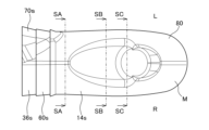
- FIG. 2 is a plan view of a three-dimensional model of the downstream side of the intake passage of the internal combustion engine in FIG. 1; 3 is a front view of the three-dimensional model of FIG. 2.
- FIG. 3 is a bottom view of the three-dimensional model of FIG. 2.
- FIG. 3 is a rear view of the three-dimensional model of FIG. 2.
- FIG. 3 is a right side view of the three-dimensional model of FIG. 2.
- FIG. 3 is a left side view of the three-dimensional model of FIG. 2.
- FIG. 3 is a perspective view from the left side of the three-dimensional model of FIG. 2.
- FIG. 3 is a perspective view from the right side of the three-dimensional model of FIG. 2.
- FIG. 6 is a perspective view of the three-dimensional model shown in FIG. 5, and is a diagram schematically showing atomized fuel injected from a fuel injection valve.
- FIG. 11 is a perspective view of the three-dimensional model shown in FIG. 2, schematically showing atomized fuel injected from a fuel injection valve in the same way as shown in FIG. 10.
- 11 is a cross-sectional view of the three-dimensional model of FIG. 2 taken along the intake flow direction, schematically showing the atomized fuel injected from the fuel injection valve in the same way as shown in FIG. 10.
- FIG. 11 is a cross-sectional view of the three-dimensional model of FIG. 2 having atomized fuel injected from a fuel injection valve in the same way as shown in FIG.
- FIG. 10 is a cross-sectional view at a position along the line SA-SA of FIG. 2.
- 11 is a cross-sectional view of the three-dimensional model of FIG. 2 having atomized fuel injected from a fuel injection valve in the same way as shown in FIG. 10, and is a cross-sectional view at a position along line SB-SB of FIG. 2.
- 11 is a cross-sectional view of the three-dimensional model of FIG. 2 having atomized fuel injected from a fuel injection valve in the same manner as shown in FIG. 10, and is a cross-sectional view at a position along line SC-SC of FIG. 2.
- 14 is a perspective view of a portion of the three-dimensional model shown in FIG. 13, corresponding to the three-dimensional model of FIG. 13A.
- FIG. 14 is a perspective view of a portion of the three-dimensional model shown in FIG. 13, and corresponds to the three-dimensional model of FIG. 13B. 14 is a perspective view of a portion of the three-dimensional model shown in FIG. 13, corresponding to the three-dimensional model of FIG. 13C.
- FIG. 1 is a schematic configuration diagram of an internal combustion engine according to a first embodiment.
- FIG. 16 is a plan view of a three-dimensional model centered on a portion from the combustion chamber to the intake system of the internal combustion engine of FIG. 15; 17 is a bottom view of the three-dimensional model of FIG. 16.
- FIG. FIG. 17 is a side view of the three-dimensional model of FIG. 16;
- FIG. 19 is a side view corresponding to FIG.
- FIG. 6 is a side view of a three-dimensional model incorporating the three-dimensional model of FIG. 5 regarding the internal combustion engine of FIG. 1 as a reference example.
- FIG. 7 is a side view of a three-dimensional model having an intake structure of an internal combustion engine according to a second embodiment. It is a figure showing a computer simulation result. It is a figure showing a computer simulation result. It is a figure showing a computer simulation result. It is a figure showing a computer simulation result. It is a figure showing a computer simulation result. It is a figure showing a computer simulation result. It is a figure showing a computer simulation result. It is a graph showing experimental results regarding the relationship between the offset amount of the tumble passage and the axial inclination of the tumble flow.
- FIG. 3 is an explanatory diagram for explaining the offset amount of the tumble passage.
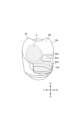
- FIG. 1 is a cross-sectional view of the internal combustion engine 10 along the axis (cylinder axis) C of the cylinder bore 12b of the cylinder block 12 of the internal combustion engine 10.
- the internal combustion engine 10 is a single cylinder engine.
- a piston 15 that reciprocates within a cylinder bore 12b of the cylinder block 12 is connected to a crank pin of a crankshaft 17 of a crankcase portion 16 by a connecting rod 18.
- a combustion chamber 20 is formed between the top surface 15a of the piston 15, which is slidably fitted into the cylinder bore 12b of the cylinder block 12, and the combustion chamber ceiling surface 14a of the cylinder head 14, which the top surface 15a faces. Ru.
- the internal combustion engine 10 employs an SOHC type two-valve system, and the cylinder head 14 is provided with a valve mechanism 22.
- a cylinder head cover 24 is placed over the cylinder head 14 so as to cover the valve mechanism 22.
- an endless cam chain (not shown) is provided on one side of the crankcase portion 16, the cylinder block 12, and the cylinder head 14 in the crankshaft direction.
- the camshaft 26 is installed between the camshaft 26 and the crankshaft 17 through the cam chain chamber, and the camshaft 26 rotates in synchronization with the crankshaft 17 at a rotation speed of 1/2.
- a spark plug is inserted into the combustion chamber 20 from the side opposite to the cam chain chamber (the other side in the crankshaft direction) in the cylinder head 14.
- the spark plug facing the combustion chamber 20 is located on the front side of the page, and the cam chain chamber is located on the back side of the page.
- an intake port 32 and an exhaust port 34 are formed to curve and extend vertically away from each other from an intake valve port 28 and an exhaust valve port 30 that are open to the combustion chamber ceiling surface 14a. Note that, as described above, a two-valve system is adopted, and the cylinder head 14 is defined with a single intake port 32 and a single exhaust port 34.
- the upstream end of the intake port 32 opens toward the upper side of the cylinder head 14 and is connected to the inlet pipe 36 to form a continuous intake passage 38.
- a throttle body 40 is connected to the upstream side of the inlet pipe 36.
- Ru is connected to the upstream side of the inlet pipe 36.
- a downstream end of the exhaust port 34 opens toward the bottom of the cylinder head 14 and is connected to an exhaust pipe 42.
- An exhaust purification device and a muffling device may be provided downstream of the exhaust pipe 42.
- a cylindrical intake valve guide 44 is integrally fitted into the curved outer wall portion 32a of the intake port 32 in the cylinder head 14.
- An intake valve 46 slidably supported by an intake valve guide 44 opens and closes an intake valve port 28 of the intake port 32 facing the combustion chamber 20.
- an exhaust valve 50 that is slidably supported by an exhaust valve guide 48 that is integrally fitted to the curved outer wall portion 34a of the exhaust port 34 in the cylinder head 14 has an exhaust valve port that faces the combustion chamber 20 of the exhaust port 34. Open and close 30.
- the intake valve 46 and the exhaust valve 50 are urged upward by a valve spring so that their umbrella parts 46a and 50a close the intake valve port 28 and the exhaust valve port 30 facing the combustion chamber 20.
- the stem ends 46b and 50b of the intake valve 46 and exhaust valve 50 are pushed down by the intake rocker arm 56 and exhaust rocker arm 58, which swing in contact with the intake cam and exhaust cam of the camshaft 26, and the intake valve 46 and the exhaust valve 50 are pushed down at a predetermined timing.
- the exhaust valve 50 opens, and the intake port 32 and the combustion chamber 20 communicate with each other, and the exhaust port 34 and the combustion chamber 20 communicate with each other, so that intake and exhaust are performed at predetermined timings.
- An inlet pipe 36 is connected to the upstream end of the intake port 32 of the internal combustion engine 10 via an insulator 60 to form a continuous intake passage 38, and a throttle body 40 is connected to the upstream side of the inlet pipe 36. be done.
- the throttle body 40 has an intake passage 40a having a substantially circular cross section and forming a part of the intake passage 38 connected to the combustion chamber 20 of the internal combustion engine 10, and the upstream side of the intake passage 40a is connected to an air cleaner device (not shown).
- the throttle body 40 is rotatably supported within the throttle body 40 by a throttle valve shaft 40b that is perpendicular to the flow direction of intake air in the intake passage 40a, that is, perpendicular to the center axis of the intake passage 40a.
- the intake passage 40a is provided with a throttle valve 40c that can variably control the flow passage area of the intake passage 40a and open/close the intake passage 40a.
- the throttle valve 40c is of a butterfly type and includes a throttle valve shaft 40b and a disc-shaped valve body 40d that is fixed to the throttle valve shaft 40b and rotates integrally with the throttle valve shaft 40b.
- the throttle valve 40c can be rotated clockwise in the valve opening direction in FIG. 1 by the driver's operation, and a return spring (not shown) causes the valve body 40d to have its edge inside the intake passage 40a. It is biased counterclockwise in the valve closing direction so that it is in the fully closed position where it contacts the wall surface.
- the throttle valve 40c is controlled, for example, to open the intake passage 40a to a predetermined small opening degree in a low-load operating state, and to fully open the intake passage 40a in a high-load operating state.
- the intake structure S0 provides a tumble vortex flow, that is, a vertical rotation, of the fuel/air mixture in the combustion chamber 20 in order to obtain more preferable combustion of the fuel or mixture in the combustion chamber 20.
- the intake structure S0 includes a partition 62 provided in the intake passage 38 so as to divide the intake passage 38 into a plurality of parts in the direction of the cylinder axis C. That is, the intake passage 38 is divided along the intake flow direction by a partition 62 that extends from the inlet pipe 36 to the intake port 32, and the intake passage 38 is configured to generate a tumble flow within the combustion chamber 20. It is partitioned into a tumble passage 64 and a main passage 66 excluding the tumble passage 64.
- the tumble passage 64 corresponds to a first intake passage
- the main passage 66 corresponds to a second intake passage. Note that the tumble passage 64 may also be referred to as a sub-passage.
- the partition portion 62 extending in a plate shape in the intake flow direction substantially extends substantially parallel to the axis extending in the flow direction so as to substantially bisect the downstream side of the intake passage 38 in the vertical direction. It is set up like this.
- the cross-sectional area of the tumble passage 64 is smaller than the cross-sectional area of the main passage 66.
- the partition portion 62 may be provided such that the cross-sectional area of the tumble passage 64 is larger than the cross-sectional area of the main passage 66, or they may be made substantially the same.
- the lower part of the intake passage 38 partitioned by the partition part 62 is the tumble passage 64, and the upper part is the main passage 66, but in this specification they are not limited to their vertical arrangement.
- "upper” and “lower” with respect to the intake passage 38, etc. refer to the direction from the crankshaft 17 side to the cylinder head 14 or cylinder head cover 24 side in the direction of the cylinder axis C. ” direction, and the direction opposite to this “up” direction, that is, the direction from the cylinder head 14 side to the crankshaft 17 side, is called the “down” or “down” direction, and is the absolute “up” and “down” direction in space. ” does not mean.
- This "up” or “up” direction corresponds to the first direction
- the "down” or “down” direction corresponds to the second direction.
- an intake control valve may be further provided upstream of the partition portion 62 and downstream of the throttle valve 40c.
- This intake control valve may be provided to variably control the flow area of the main passage 66, for example.
- the intake control valve may also be referred to as a tumble valve, tumble control valve, or TCV, and is controlled to, for example, fully close the main passage 66 in a low-load operating state and fully open the main passage 66 in a high-load operating state.
- Ru The throttle valve 40c is electronically controlled as described below, but is not limited to being electronically controlled. For example, it may be a valve that is mechanically controlled by a throttle cable, and this may be a valve that is controlled mechanically by a throttle cable. The same applies when a valve is provided.
- the internal combustion engine 10 is provided with fuel injection valves 68 and 70.
- One fuel injection valve (hereinafter referred to as a first fuel injection valve) 68 is provided upstream of the upstream end 62u of the partition portion 62, and is located in the intake passage 38 upstream of the upstream end 62u. It is provided to inject fuel into the area.
- the other fuel injection valve (hereinafter referred to as a second fuel injection valve) 70 is provided to inject fuel into the intake port 32.
- the second fuel injection valve 70 is provided so as to face the main passage 66, and is provided in the inlet pipe 36 here. In this way, the second fuel injection valve 70 is provided to inject fuel from the main passage 66 side and supply the fuel to the combustion chamber 20 via the intake port 32.
- the second fuel injection valve 70 is attached to the upper wall of the member defining the intake passage 38. Note that the present disclosure does not limit the number of fuel injection valves to two, and may be one, for example. In this case, for example, only the second fuel injection valve 70 can be provided.
- An ECU (electronic control unit) 72 that controls the internal combustion engine 10 has a configuration as a so-called computer, and includes an intake control section 74 and a fuel injection control section 76. That is, the ECU 72 includes a processor (eg, CPU) and memory (eg, ROM and RAM). The ECU 72 analyzes the operating state of the internal combustion engine 10 based on outputs from various sensors such as an engine speed sensor and an engine load sensor, and controls the operation of the throttle valve 40c using the intake control section 74. Furthermore, the ECU 72 controls each operation of the fuel injection valves 68 and 70 using a fuel injection control section 76 based on the analyzed operating state of the internal combustion engine 10. Note that the ECU 72 stores programs and various data for these controls.
- a processor eg, CPU
- memory eg, ROM and RAM
- the ECU 72 analyzes the operating state of the internal combustion engine 10 based on outputs from various sensors such as an engine speed sensor and an engine load sensor, and controls the operation of the throttle valve 40
- FIGS. 2 to 9 a three-dimensional model M of the downstream side of the intake passage 38 is shown in FIGS. 2 to 9.
- the three-dimensional model M includes an intake port 32 from the downstream end of the inlet pipe 36, and terminates at the intake valve port 28 on the downstream side.
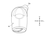
- the three-dimensional model M is a model of the downstream end of the intake passage 38, so the outer surface 80 of the three-dimensional model M includes the inner surface 36s of the inlet pipe 36, which is a member that defines the downstream side of the intake passage 38, and the insulator. 60 and an inner wall surface 14s of the cylinder head 14, a portion corresponds to a surface 62s of the partition portion 62, and a portion corresponds to a surface 90s of a deflection portion 90, which will be described later.
- the symbol “U” is used for the upper side
- the symbol “D” is used for the lower side
- the symbol “R” is used for the right side when looking from the upstream side to the downstream side in the intake flow direction
- the suffix "L” is used on the left side.
- the width of the partition portion 62 in the left-right direction (LR direction) intersecting the cylinder axis C, that is, the width in the width direction, is on the upstream side of the partition portion 62 on the downstream side. It has a deflection section 90 that is narrower than the end (upstream end) 62u.
- the deflection portion 90 extends from one side of the valve axis of the intake valve 46 to the other side when facing the intake valve 46 in the direction in which intake air flows through the intake passage 38 from the upstream side to the downstream side, that is, in the intake flow direction.
- This is the narrow portion of the partition portion 62 in the width direction which can be defined as a direction. As shown in FIG.
- the width W2 of the downstream end portion 64d is clearly narrow. Since the partition portion 62 is formed so as to partition the tumble passage 64 in the intake passage 38, the deflection portion 90 with respect to the width W2 portion is relatively narrow.
- the deflecting portion 90 is biased in one direction in the left-right direction, that is, in the width direction.
- the downstream end portion 64d of the tumble passage 64 is partitioned so as to be biased toward the right R side. Therefore, the downstream biased portion 90 of the partition portion 62 that at least partially defines the biased downstream end portion 64d of the tumble passage 64 is biased to the right R side here. Therefore, in FIG. 1, the cylinder axis C extends parallel to the plane of the paper, and the width direction extends substantially perpendicular to the plane of the paper, so the deflection part 90 extending downstream of the partition part 62 does not appear. Therefore, it is shown as a double-dashed line instead of a solid line. Therefore, the merging portion 65 between the main passage 66 and the tumble passage 64 is biased toward the right R side.
- the mounting portion 70s of the second fuel injection valve 70 is positioned on the left L side of the intake passage 38, as is clear from FIGS. 6 and 7. In this way, the second fuel injection valve 70 is provided at a position that is biased in the direction opposite to the direction in which the deflection portion 90 is biased. In this way, the second fuel injection valve 70 is provided so as to be able to inject fuel in a direction different from the direction in which the deflection portion 90 is biased, and more preferably in the opposite direction. Note that the second fuel injection valve 70 is provided on the upper side, that is, on the main passage 66 side, and injects fuel from the main passage 66 side.
- FIG. 10 which is a perspective view of the three-dimensional model M shown in FIG. 5
- the sprayed fuel F injected from the second fuel injection valve 70 provided at a position biased toward the left L side is schematically shown.
- FIG. 11 shows a perspective view of the three-dimensional model M, which schematically shows the sprayed fuel F injected from the fuel injection valve in the same way as shown in FIG. 10.
- FIG. 12 shows a cross-sectional view of the three-dimensional model M along the intake flow direction, schematically showing the atomized fuel F injected from the fuel injection valve in the same way as shown in FIG. From FIGS.
- the fuel F injected from the second fuel injection valve 70 is not blocked by the partition part 62, and at least a part of it, especially at least a majority of it here, more preferably all of it, It can be seen that the air first flows through the main passage 66, then flows to the confluence 65 between the main passage 66 and the tumble passage 64, and then directly reaches the intake valve port 28 and is introduced into the combustion chamber 20.
- the arrangement of the second fuel injection valve 70, the shape of the partition portion 62 including the deflection portion 90, etc. are designed to enable such fuel injection.
- the partition body 92 of the partition 62 terminates downstream thereof to allow the main passage 66 and tumble passage 64 to merge, and also preferably extends along the surface 90s of the deviation part 90.
- the partition main body part 92 and deflection part 90 of the partition part 62 are designed so that the fuel F injected from the second fuel injection valve 70 reaches the intake valve port 28 without touching the fuel injector 70 (for example, see FIG. 11). ).
- FIGS. 13A to 14C cross-sectional views of the three-dimensional model M including the injected fuel F in FIG. 10 are shown in FIGS. 13A to 14C.
- FIG. 13A is a cross-sectional view of the three-dimensional model M at a position along the line SA-SA in FIG. 2
- FIG. 13B is a cross-sectional view of the three-dimensional model M at a position along the line SB-SB in FIG. 13C is a cross-sectional view of the three-dimensional model M at a position along line SC-SC in FIG. 2.
- 14A to 14C are perspective views of the 3D model M in FIGS. 13A to 13C
- the 3D model in FIG. 14A corresponds to the 3D model in FIG. 13A
- the 3D model in FIG. 14B corresponds to the 3D model in FIG. 13B.
- the three-dimensional model in FIG. 14C corresponds to the three-dimensional model in FIG. 13C.
- FIGS. 13A and 14A At the cutting locations in FIGS. 13A and 14A, the tumble passage 64 and the main passage 66 are completely separated. At the position of the SA-SA line in FIG. A partition main body portion 92 extending to the upstream side extends. In addition, in FIGS. 13A and 14A, the surface 62s of the partition portion 62 and the portions corresponding to the surface 92s of the partition main body portion 92 are given the same reference numerals.
- the tumble passage 64 and the main passage 66 are partially connected. Further, in the cut planes of FIGS. 13B and 14B, the surface 62s of the partition portion 62 extends in the width direction and also extends in the vertical direction, and is biased to the right side. From this, at the position of the SB-SB line in FIG. It can be seen that the intake port 32 extends to the left from the right side of the inner wall surface 14s of the cylinder head 14 to the extent that the intake port 32 is not separated from the intake port 32.
- the tumble passage 64 and the main passage 66 are formed into sections such that the main passage 66 and the tumble passage 64 communicate with each other in the region where the deflection portion 90 extends in the intake flow direction.
- the deflection section 90 connected to the partition main body 92 extends downstream of the partition main body 92 so that a part of the partition main body 92 of the partition 62 extends in the flow direction. It is formed to extend to the side.
- the surface 62s of the partition portion 62 and the portions thereof corresponding to the surface 90s of the deflection portion 90 are labeled with those symbols, and this is the same in FIGS. 13C and 14C. .
- the amount of leftward protrusion of the deflection portion 90 from the inner wall surface 14 of the cylinder head 14 is reduced compared to the cut locations in FIGS. 13B and 14B.
- the deflection portion 90 is formed so as to become narrower toward the downstream side in the intake flow direction.
- the degree of communication between the main passage 66 and the tumble passage 64 is increased at the cut locations shown in FIGS. 13C and 14C than at the cut locations shown in FIGS. 13B and 14B. That is, the amount of connection between the tumble passage 64 and the main passage 66 at the cutting positions in FIGS. 13C and 14C is greater than the amount of connection between them at the cutting positions in FIGS.
- the tumble passage 64 and the main passage 66 are partitioned so that the main passage 66 extends downward to the side or side of the deviation part 90 in the region where the deviation part 90 extends in the intake flow direction. It is formed.
- This downward expansion of the main passage 66 is performed in a direction opposite to the direction in which the deflection section 90 is biased, and here, it is performed on the left L side of the deflection section 90. Note that this downward expansion of the main passage 66 and the resulting fusion of the main passage 66 and the tumble passage 64 are more pronounced on the downstream side of the deflection portion 90.
- the second fuel injection valve 70 which is provided to inject the fuel F from the main passage 66 side toward the combustion chamber 20, It is designed to inject fuel in the opposite direction. Therefore, the partition portion 62, particularly its deflection portion 90, can be extended further downstream in the intake flow direction.
- the tumble passage 64 is formed into sections so as to be biased on the downstream side in the direction in which the deflection portion 90 is biased. Therefore, the deflection portion 90 of the partition portion 62 that extends further downstream in the intake flow direction can provide stronger directivity to the intake air from the tumble passage 64.
- the partition part 62 completely partitions the main passage 66 and the tumble passage 64 with the partition main part 92 on the upstream side, and has the deflection part 90 on the downstream side thereof to separate the main passage 66 and the tumble passage. It is designed to realize the connection with the passage 64 while characterizing the flow from the tumble passage 64 further downstream.
- the second fuel injection valve 70 is disposed biased to the opposite side to the biased direction of the biased portion 90, and here is disposed on the opposite side in the width direction, and injects fuel in a direction different from the biased portion 90.
- the fuel can be introduced into the combustion chamber 20 almost directly through the intake valve port 28. In other words, it is possible to ensure a good supply of fuel to the combustion chamber.
- the deflection portion 90 which is the downstream portion of the partition portion 62, can be extended further downstream. Therefore, stronger directivity can be given to the flow from the tumble passage 64.
- This directivity is oriented between the intake valve port 28 and the umbrella portion 46a of the intake valve 46 when the valve is open so as to form a stronger tumble flow in the combustion chamber 20, so that the intake air from the tumble passage 64 is A tumble flow can be suitably formed by the combustion chamber 20.
- the tumble passage 64 communicates with the main passage 66 at the downstream edge of the partition part 62, that is, downstream of the downstream edge 90d of the deflection part 90, so as to form a single intake passage connected to the combustion chamber 20.
- the tumble passage 64 and the main passage 66 are divided into sections. This allows intake air from the tumble passage 64 to be introduced into the combustion chamber 20 along with intake air from the main passage 66, and intake air from the single intake port 32, which is a single intake passage, to introduce fuel into the combustion chamber 20. It becomes possible to create a supply and a tumble flow formation. Note that this configuration can suppress an increase in the number of parts and is also excellent in terms of cost.
- the intake structure S0 of the internal combustion engine 10 having the above configuration has excellent functions and effects, but in addition to this configuration, the present invention also has a configuration aimed at further strengthening the tumble flow.
- the internal combustion engine 110 according to the first embodiment of the invention, particularly its intake structure S, will be described below.
- the intake structure S of the internal combustion engine 110 generally has the above-described configuration of the intake structure S0 of the internal combustion engine 10, and has additional configurations or features.
- the same reference numerals as those already used will be used for components that correspond to or correspond to those already described, and further redundant explanation will be omitted.
- the internal combustion engine 110 is a single cylinder engine, the internal combustion engine to which the present invention is applied is not limited to a single cylinder engine, and may be a multi-cylinder engine.
- the internal combustion engine 110 does not include the first fuel injection valve 68, but includes a fuel injection valve 70a corresponding to the second fuel injection valve.
- the internal combustion engine 110 may include the first fuel injection valve 68.
- the internal combustion engine 110 includes the above-mentioned tumble valve 94c so that the main passage 66 partitioned by the partition portion 62 can be opened and closed.
- a tumble valve body 94 is connected to the upstream end of the inlet pipe 36 via an insulator 95.
- the tumble valve body 94 has an intake passage 94a having a substantially circular cross section and forming a part of the intake passage 38, and the aforementioned throttle body 40 is connected to the upstream end of the intake passage 94a.
- the tumble valve body 94 is rotatably supported within the tumble valve body 94 by a valve shaft 94b that is perpendicular to the intake flow direction of the intake passage 94a, that is, perpendicular to the center axis of the intake passage 94a.
- a tumble valve 94c is provided which can variably control the flow path area of the intake path 94a and open and close the upper area of the intake path 94a in cooperation with the partition portion 62.
- the operation of the tumble valve 94c is electronically controlled here according to the operating state of the internal combustion engine 110, but is not limited thereto.
- the tumble valve 94c is controlled, for example, to fully close the main passage 66 in a low load operating state and to fully open the main passage 66 in a high load operating state.
- the tumble valve 94c is of a butterfly type and includes a valve shaft 94b and a substantially disc-shaped valve body 94d that is fixed to the valve shaft 94b and rotates integrally with the valve shaft 94b.
- the tumble valve 94c is configured to include the valve body 94d, which is a single valve member that rotates integrally with the valve shaft 94b.
- the valve shaft 94b of the tumble valve 94c is parallel to the throttle valve shaft 40b.
- the internal combustion engine 110 has a feature regarding the tumble passage 64.
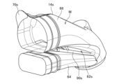
- the tumble passage 64 will be explained based on FIGS. 16 to 18.
- FIG. 16 to 18 show a three-dimensional model M1 centered on the downstream side of the intake system from the upper part of the combustion chamber 20 of the internal combustion engine 110, for example, the intake port 32.
- FIG. 16 is a plan view or top view of the three-dimensional model M1, which corresponds to the plan view (FIG. 2) of the internal combustion engine 10
- FIG. 17 is a bottom view of the three-dimensional model M1, which corresponds to the bottom view ( 4)
- FIG. 18 is a side view of the three-dimensional model M1, and corresponds to a rear view of the internal combustion engine 10 (FIG. 5).
- the intake passage 38 connected to the combustion chamber 20 is divided into a tumble passage 64, which is a first intake passage, and a second intake passage, by a partition portion 62 in the direction of the cylinder axis C. It is divided into 66 main passages.
- the main passage 66 is provided above the tumble passage 64 in the direction of the cylinder axis C.
- the tumble passage 64 In a top view from the direction of the cylinder axis C (FIG. 16), the tumble passage 64 generally overlaps the main passage 66, and the merging part 65 of the tumble passage 64 with the main passage 66 is the opening of the intake port 32, that is, the intake It is biased toward the valve port 28, and here, as already explained, it is biased to the right R side.
- the tumble passage 64 provided to generate a tumble flow in the combustion chamber 20 is curved away from the main passage 66 in the direction of the cylinder axis C, and is perpendicular to the cylinder axis C. At the same time, it is formed to be curved in the width direction perpendicular to the intake and exhaust direction.
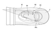
- a virtual plane IS is drawn in FIGS. 16 and 17 that includes the cylinder axis C and extends in the intake and exhaust direction.
- This virtual surface IS is a virtual surface that extends in the intake and exhaust direction, passes through the center of the intake valve port 28 and the exhaust valve port 30, and includes the cylinder axis C, and is represented as a line (center line) Lx in FIGS. 16 and 17. has been done.
- Lx center line
- the right-hand contour 64r of the tumble passage 64 is not parallel to the center line Lx, but is curved convexly to the outer right.
- the contour 64r goes from the upstream side to the downstream side in the intake flow direction, it first widens to protrude to the right outside, passes through the maximum right protrusion 64s, and extends toward the center line Lx side. That is, in the top view of FIG. 16, the tumble passage 64 is formed to curve convexly toward the same side as the side where the merging portion 65 is biased.
- the tumble passage 64 is formed to be perpendicular to the cylinder axis C and curved in the width direction, that is, the left-right direction, that is perpendicular to the intake and exhaust direction, that is, the line Lx.
- the tumble passage 64 is curved away from the main passage 66.
- the partition part 62 is provided in the middle of the intake passage 38, and is provided so that the tumble passage 64 branches from the main passage 66, and the tumble passage 64 joins the main passage 66 on the downstream side thereof.
- the tumble passage 64 curves convexly on the side opposite to the main passage 66. More specifically, the tumble passage 64 is formed to curve convexly toward the crankshaft 17 in the direction of the cylinder axis C, that is, curve convexly downward.
- a plane or line Ly is drawn that is perpendicular to the cylinder axis C and in contact with the lower contour 64t of the tumble passage 64.
- the contour 64t extends from the upstream side to the downstream side in the intake flow direction, first protruding downward, passing through the maximum lower protrusion 64u, and extending upward.
- the contour 64t touches the line Ly not at both ends but at the maximum protrusion 64u.
- the vertical width of the tumble passage 64 does not change significantly from the upstream side to the downstream side in the intake flow direction. Therefore, in the internal combustion engine 110, the tumble passage 64 is curved in the direction of the cylinder axis C in a side view (FIG.
- the tumble passage 64 is curved in the direction of the cylinder axis C. It is curved in a substantially U-shape so as to be convex to the lowest side in the direction of the cylinder axis C. Therefore, in FIG. 18, the downstream portion 64L of the tumble passage 64 is formed so as to approach the cylinder head 24 from the crankshaft 17 side in the direction of the cylinder axis C as it reaches the downstream side in the intake flow direction.
- the downstream portion 64L of the tumble passage 64 includes a portion downstream of the maximum protrusion 64u in the tumble passage 64.
- the curved shape of the contour 64t is as follows in a side view from a direction perpendicular to the cylinder axis C, that is, in FIG. The same applies to the wall surface ds of the partition portion 62 that defines the tumble passage 64. That is, in FIG. 18, the wall surface ds of the partition portion 62 defining the tumble passage 64 is curved so as to be convex toward the crankshaft 17 in the direction of the cylinder axis C.
- FIG. 16 when viewed from above in the direction of the cylinder axis C, there is a merging portion 65 on one side of a virtual plane IS that includes the cylinder axis C and extends in the intake and exhaust direction, here on the right R side. , a spark plug facing the combustion chamber 20 is arranged. In FIG. 16, the ignition part p of the spark plug is shown.
- FIG. 20 shows a three-dimensional model M2 incorporating the three-dimensional model M of the intake structure S0 of the internal combustion engine 10 of the reference example.
- the throttle valve 40c and the tumble valve 94c on the downstream side thereof are provided, although not shown, as already explained.
- the intake passage 38 is divided by the partition portion 62, and a main passage 66 is formed above the tumble passage 64. That is, in the direction of the cylinder axis C, a tumble passage 64 for generating a tumble flow in the combustion chamber 20 and a main passage 66 are provided in the intake passage 38 connected to the combustion chamber 20 so as to overlap with each other.
- the tumble passage 64 is formed to be curved in a width direction that is perpendicular to the cylinder axis C and perpendicular to the intake and exhaust direction.
- the intake air from the tumble passage 64 is on the right side of the intake air from the main passage 66. It flows into the combustion chamber 20 from the merging portion 65. This reduces the degree to which the intake air from the tumble passage 64 is interfered with by the intake air from the main passage 66, making it possible to suitably form a tumble flow in the combustion chamber.
- the tumble passage 64 is curved away from the main passage 66 in the direction of the cylinder axis C. Therefore, the intake air from the tumble passage 64 can smoothly flow into the combustion chamber 20 so as to form a tumble flow. Therefore, a stronger tumble flow can be generated in the combustion chamber.
- the merging portion 65 is biased with respect to the opening 28 of the intake port 32 when viewed from above in FIG. Therefore, during the intake stroke, the intake valve 46 opens and the flow of intake air flowing into the combustion chamber can be set at an angle corresponding to its bias. Further, the tumble passage 64 is formed to curve convexly toward the same side as the side where the merging portion 65 is biased. Therefore, the degree to which the intake air from the tumble passage 64 interferes with the intake air from the main passage 66 can be further reduced, making it possible to suitably form a tumble flow in the combustion chamber.
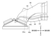
- the tumble passage 64 is formed to curve convexly toward the crankshaft 17 in the direction of the cylinder axis C. Therefore, it is possible to actively encourage the intake air from the tumble passage 64 to separate from the wall portion forming the tumble passage 64 at the confluence portion 65, particularly from the wall portion 64w defining the lower contour 64t of the tumble passage 64.
- the flow of intake air from the tumble passage 64 at this time is shown by arrow A3 in FIG. This makes it possible to increase the flow rate of intake air from the tumble passage 64 and generate a stronger tumble flow.
- the tumble passage 64 is formed to curve convexly toward the crankshaft 17 in the direction of the cylinder axis C, the position of the merging portion 65 is as shown in FIG. The position will be above the part 46s where it hits. By adjusting the position of this merging portion 65 based on experiments or the like, the direction of the intake air from the tumble passage 64 can be optimized, and the generation of the tumble flow can be further promoted.
- the downstream portion 64L of the tumble passage 64 is formed so that the further downstream in the intake flow direction, the closer it gets from the crankshaft 17 side to the cylinder head 24 side in the direction of the cylinder axis C. . Therefore, it is possible to more actively encourage the intake air from the tumble passage 64 to separate from the wall portion 64w defining the lower contour 64t of the tumble passage 64.
- the wall surface ds of the partition portion 62 defining the tumble passage 64 is curved so as to be convex toward the crankshaft 17 in the direction of the cylinder axis C. Therefore, the vertical widths of the tumble passages can be made approximately the same, and the intake air from the tumble passage 64 can be directed to generate more tumble flow.
- the wall surface ds is a wall surface on the main passage 66 side that defines the tumble passage 64.
- the merging portion 65 and the spark plug facing the combustion chamber 20 are arranged on one side of a virtual plane IS that includes the cylinder axis C and extends in the intake and exhaust direction, here on the right R side. ing. Therefore, the intake air from the tumble passage 64 makes it possible to more quickly carry the spark from the ignition plug to the center of the combustion chamber, thereby making it possible to further increase the flame propagation speed.
- the internal combustion engine of the second embodiment has the features of the internal combustion engine 110 of the first embodiment, such as the above configuration of the tumble passage 64, but has additional features with respect to the configuration of the main passage 66 compared to the internal combustion engine 110. Its characteristics will be explained based on FIG. 21.
- FIG. 21 shows a three-dimensional model M3 having an intake structure S1 of an internal combustion engine according to the second embodiment.
- a throttle valve 40c and a tumble valve 94c (not shown) are provided on the upstream side of the tumble passage 64 and the main passage 66, and the throttle valve 40c is fully opened and the tumble valve 94c is fully closed. There is.
- the downstream wall surface us of the partition portion 62 that partitions the main passage 66 is This is a downstream wall surface that defines the tumble passage 64 side of 66, and has a curved shape corresponding to the curved shape of the downstream portion 64L of the tumble passage 64.
- the curved shape of the downstream wall surface us is similar to or close to, preferably the same as, the curved shape of the downstream portion 64L.
- the downstream portion 64L of the tumble passage 64 approaches the cylinder head 24 from the crankshaft 17 side in the direction of the cylinder axis C as it reaches the downstream side in the intake flow direction. is formed.
- the downstream wall surface us of the partition portion 62 that defines the main passage 66 has this upwardly curved shape. Since the downstream wall surface us has this curved shape, the downstream wall surface us has a downwardly convex curved shape or a curved shape close to it.
- the downstream wall surface us of the partition portion 62 that partitions and forms the main passage 66 has the above-described configuration, for example, when the tumble valve 94c is in an operating state where it is closed, the intake air of the main passage 66 (see arrow A4) is us and can jump towards the combustion chamber 20 and is directed to smoothly merge with the intake air from the tumble passage 64 (see arrow A5). This makes it possible to promote the generation of a stronger tumble flow.
- Example 2 A computer simulation was performed on the intake structure S of the internal combustion engine according to the first embodiment. As a comparative example, a computer simulation was also performed for the intake structure S0 of an internal combustion engine as a reference example. In the computer simulation, the throttle valve 40c was fully opened and the tumble valve 94c was fully closed.
- FIGS. 22 to 24 the results of the first computer simulation are shown in FIGS. 22 to 24.
- the flow of intake air from the intake port 32 side to the combustion chamber 20 when looking at the combustion chamber 20 side from a direction perpendicular to the cylinder axis C was calculated.
- the intake air flows are shown so that the faster the flow rate, the darker the intake air flows. Note that 360° of the crank angle (deg) corresponds to the top dead center.
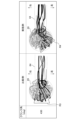
- FIGS. 25 and 26 the results of the second computer simulation are shown in FIGS. 25 and 26.
- curvature of the tumble passage 64 in the width direction perpendicular to the cylinder axis C and perpendicular to the intake/exhaust direction, that is, curvature to the right (see FIGS. 16 and 17) In order to verify the effect, the flow of intake air from the intake port 32 side to the combustion chamber 20 when looking at the combustion chamber 20 side from above in the direction of the cylinder axis C was calculated.
- FIGS. 25 and 26 the intake air flow is shown so that the faster the intake air flow, the darker the line. Note that 360° of the crank angle (deg) corresponds to the top dead center.
- the fast intake air from the intake tumble passage 64 flows into the combustion chamber 20 from the right side at an angle.
- the inflow path indicated by the black line in the comparative example is generally in the intake/exhaust direction (see direction mark R3), but the inflow path indicated by the black line in the example is inclined with respect to the intake/exhaust direction. The direction was angled from the right side to the left side (see direction mark R4).
- the curvature of the tumble passage 64 in the width direction makes it possible to angle the flow into the cylinder during the intake stroke, thereby tilting the rotation axis of the positive tumble flow. It can be seen that the intake air from the tumble passage 64 can be caused to flow into the combustion chamber 20 from the right side. This is suitable for promoting flame propagation from the spark plug on the right side where the tumble passage 64 is biased.
- Figures 27 to 29 show the results of five simulations.
- Three of the five simulations are simulations using a model having the configuration of the internal combustion engine 110 of the first embodiment, and assuming the same curvature of the tumble passage 64 in the direction of the cylinder axis C (see FIG. 18), The degree of curvature of the tumble passage 64 to the right was varied.
- the results are shown in FIGS. 27 to 29 as plots P1 to P3. That is, for example, the plots P1 in FIGS. 27 to 29 are obtained by the same simulation.
- the results obtained by simulation using a model having the configuration of the internal combustion engine 10 of the reference example are shown in broken lines in FIGS.
- the swirl ratio is small and the tumble ratio is large.
- the axis of rotation of the tumble flow is preferably inclined to the right side where the spark plug is provided, and the more the axis of rotation of the tumble flow is inclined to the right side, the more the vertical axis in FIG. Axial tilt increases.
- the tumble passage 64 is biased to the right and curved, but it may be biased and curved to the left.
- the merging portion 65 and the spark plug are preferably provided on the left side of the virtual surface IS.
- the intake structures S and S1 of the internal combustion engine of the first and second embodiments have the characteristics of the intake structure S0 of the reference example, such as the deflection portion 90, they may not have this deflection portion. It is possible.
- the tumble passages 64 of the intake structures S and S1 may be formed to be completely independent from the main passage 66 up to the merging portion 65 with the main passage 66.
Abstract
The present disclosure is directed to providing a configuration that makes it possible to generate a stronger tumble flow in a combustion chamber in an internal combustion engine in which a passageway for a tumble flow and another passageway are provided so as to overlap each other in an intake passageway in the direction of the cylinder axis line. In an intake structure S of an internal combustion engine according to an embodiment, a first intake passageway 64 is formed so as to curve away from a second intake passageway 66 in the direction of a cylinder axis line C, and so as to curve in a width direction which is orthogonal to the cylinder axis line C and is orthogonal to an intake/exhaust direction.
Description
本発明は、タンブル流用の通路とそれ以外の通路とを吸気通路に備える内燃機関の吸気構造に関する。
The present invention relates to an intake structure for an internal combustion engine in which an intake passage includes a tumble diversion passage and other passages.
スロットル弁の下流側の吸気通路が、仕切部により複数の通路に分けられる内燃機関の吸気構造が種々提案されている。例えば、特許文献1の内燃機関の吸気構造では、スロットル弁の下流側にタンブル弁を設け、そのタンブル弁の下流側にインレットパイプから吸気ポートへと続けて仕切部である仕切板部を設け、この仕切板部により吸気通路を上下の下側副通路と上側主通路とに仕切ることが行われる。下側副通路がタンブル通路となり、タンブル弁は上側主通路を実質的に開閉するものである。なお、上記タンブル弁は、吸気振分け弁または吸気制御弁とも称され得るバルブであり、上記仕切部が設けられた内燃機関において、設けられない場合もある(例えば特許文献2参照)。
Various intake structures for internal combustion engines have been proposed in which the intake passage on the downstream side of the throttle valve is divided into a plurality of passages by a partition. For example, in the intake structure of an internal combustion engine disclosed in Patent Document 1, a tumble valve is provided downstream of the throttle valve, and a partition plate portion that is a partition portion is provided downstream of the tumble valve from the inlet pipe to the intake port. This partition plate section partitions the intake passage into an upper and lower lower sub-passage and an upper main passage. The lower sub-passage serves as a tumble passage, and the tumble valve substantially opens and closes the upper main passage. Note that the tumble valve is a valve that can also be called an intake distribution valve or an intake control valve, and may not be provided in an internal combustion engine provided with the partition portion (see, for example, Patent Document 2).
前述のように、吸気通路を、タンブル流を生じさせるためのタンブル通路と、それ以外の通路である上側の主通路とに分けた内燃機関がある。この内燃機関では、吸気弁の開弁時に、タンブル通路からの吸気は、主通路からの吸気に干渉される場合があり、タンブル通路からの吸気によるタンブル流の形成が影響を受ける場合がある。一方で、昨今の環境への配慮の更なる高まりにより、燃焼室での燃焼性を更に改善するべく、強いタンブル流つまり正タンブル流を得ることに対する強い要求がある。本発明の目的は、シリンダ軸線の方向において吸気通路にタンブル流用の通路とそれ以外の通路とが重なるように設けられている内燃機関において、燃焼室でより強いタンブル流を生じさせることを可能にする構成を提供することにある。
As mentioned above, there is an internal combustion engine in which the intake passage is divided into a tumble passage for generating a tumble flow and an upper main passage that is another passage. In this internal combustion engine, when the intake valve is opened, the intake air from the tumble passage may be interfered with by the intake air from the main passage, and the formation of a tumble flow due to the intake air from the tumble passage may be affected. On the other hand, due to the recent increased concern for the environment, there is a strong demand for obtaining a strong tumble flow, that is, a positive tumble flow, in order to further improve the combustibility in the combustion chamber. An object of the present invention is to make it possible to generate a stronger tumble flow in the combustion chamber in an internal combustion engine in which the intake passage is provided so that a tumble flow passage and other passages overlap in the direction of the cylinder axis. The purpose is to provide a configuration for
上記目的を達成するために、本発明の一態様は、
シリンダ軸線の方向において、燃焼室に連なる吸気通路に、前記燃焼室でタンブル流を生じさせるための第1吸気通路と、第2吸気通路とが重なるように設けられている内燃機関の吸気構造であって、
前記第1吸気通路は、前記シリンダ軸線の方向において前記第2吸気通路から離れるように湾曲するとともに、前記シリンダ軸線に直交するとともに吸排気方向に直交する幅方向において湾曲するように形成されている
ことを特徴とする内燃機関の吸気構造
を提供する。 In order to achieve the above object, one aspect of the present invention is to
An intake structure for an internal combustion engine in which a first intake passage for generating a tumble flow in the combustion chamber and a second intake passage are provided in an intake passage connected to a combustion chamber so as to overlap in the direction of a cylinder axis. There it is,
The first intake passage is curved away from the second intake passage in the direction of the cylinder axis, and curved in a width direction that is perpendicular to the cylinder axis and perpendicular to the intake and exhaust direction. An intake structure for an internal combustion engine is provided.
上記構成によれば、燃焼室でタンブル流を生じさせるための第1吸気通路は、シリンダ軸線の方向において第2吸気通路から離れるように湾曲するとともに、シリンダ軸線に直交するとともに吸排気方向に直交する幅方向において湾曲するように形成される。第1吸気通路をシリンダ軸線の方向において第2吸気通路から離れるように形成することで、第1吸気通路からの吸気をタンブル流を形成するように滑らかに燃焼室に流入させることができ、第1吸気通路からの吸気の流れの流速を高めることが可能である場合もある。また、第1吸気通路をシリンダ軸線に直交するとともに吸排気方向に直交する幅方向において湾曲するように形成することで、第1吸気通路からの吸気が第2吸気通路からの吸気に干渉される度合いを下げることができる。よって、上記構成によれば、燃焼室でより強いタンブル流を生じさせることができる。
According to the above configuration, the first intake passage for generating a tumble flow in the combustion chamber is curved away from the second intake passage in the direction of the cylinder axis, and is perpendicular to the cylinder axis and perpendicular to the intake and exhaust direction. It is formed to be curved in the width direction. By forming the first intake passage away from the second intake passage in the direction of the cylinder axis, the intake air from the first intake passage can smoothly flow into the combustion chamber to form a tumble flow. It may be possible to increase the flow rate of the intake air flow from one intake passage. Furthermore, by forming the first intake passage to be curved in the width direction that is perpendicular to the cylinder axis and perpendicular to the intake and exhaust direction, the intake from the first intake passage interferes with the intake from the second intake passage. You can lower the level. Therefore, according to the above configuration, a stronger tumble flow can be generated in the combustion chamber.
好ましくは、前記シリンダ軸線の方向においてクランク軸側からシリンダヘッド側の方向を第1方向と定義するとき、前記第2吸気通路は、第1吸気通路の前記第1方向側に設けられている。この構成によれば、第2吸気通路は第1吸気通路の前記第1方向側に設けられ、かつ、前述のように第1吸気通路をシリンダ軸線の方向において第2吸気通路から離れるようにしているので、第1吸気通路が第2吸気通路に合流する箇所での、第1吸気通路からの吸気の剥離を積極的に促すことができる。よって、第1吸気通路からの吸気の流速を高めることが可能になる。
Preferably, when the direction from the crankshaft side to the cylinder head side in the direction of the cylinder axis is defined as the first direction, the second intake passage is provided on the first direction side of the first intake passage. According to this configuration, the second intake passage is provided on the first direction side of the first intake passage, and as described above, the first intake passage is separated from the second intake passage in the direction of the cylinder axis. Therefore, it is possible to actively encourage separation of intake air from the first intake passage at the location where the first intake passage joins the second intake passage. Therefore, it becomes possible to increase the flow rate of intake air from the first intake passage.
好ましくは、前記第1吸気通路の前記第2吸気通路への合流部は、前記幅方向において、吸気ポートの開口部に対して偏っている。この構成によれば、吸入行程時に吸気弁が開いて燃焼室に流入する第1吸気通路からの吸気の流れに、その偏りに応じた角度をつけることが可能になる。よって、第1吸気通路からの吸気が第2吸気通路からの吸気に干渉される度合いをより下げることができる。
Preferably, the joining portion of the first intake passage to the second intake passage is biased with respect to the opening of the intake port in the width direction. According to this configuration, the intake valve opens during the intake stroke, and the flow of intake air from the first intake passage into the combustion chamber can be set at an angle corresponding to the bias thereof. Therefore, the degree to which intake air from the first intake passage interferes with intake air from the second intake passage can be further reduced.
好ましくは、前記シリンダ軸線を含むとともに前記吸排気方向に延びる仮想面を定めるとき、前記仮想面の一方側に、前記合流部と、前記燃焼室に臨む点火プラグが配置されている。この構成によれば、第1吸気通路からの吸気により、点火プラグによる火花をより迅速に燃焼室中央側に運ぶことが可能になり、これにより火炎伝播速度をより高めることが可能になる。
Preferably, when defining an imaginary plane that includes the cylinder axis and extends in the intake and exhaust direction, the merging portion and the spark plug facing the combustion chamber are arranged on one side of the imaginary plane. According to this configuration, the spark from the ignition plug can be more quickly carried to the center of the combustion chamber by the intake air from the first intake passage, thereby making it possible to further increase the flame propagation speed.
好ましくは、前記幅方向において、前記第1吸気通路は、前記合流部が偏っている側と同じ側に凸に湾曲するように形成されている。これにより、第1吸気通路からの吸気が第2吸気通路からの吸気に干渉される度合いを更に下げることができ、よって燃焼室においてタンブル流をより好適に形成することが可能になる。
Preferably, in the width direction, the first intake passage is formed to curve convexly toward the same side as the merging portion. This makes it possible to further reduce the degree to which the intake from the first intake passage interferes with the intake from the second intake passage, thereby making it possible to more appropriately form a tumble flow in the combustion chamber.
好ましくは、前記第1吸気通路は、前記シリンダ軸線の方向においてクランク軸側に凸に湾曲するように形成されている。これにより、第1吸気通路の第2吸気通路への合流部で、第1吸気通路からの吸気が吸気通路壁面から剥離することを積極的に促すことができる。
Preferably, the first intake passage is formed to curve convexly toward the crankshaft in the direction of the cylinder axis. Thereby, it is possible to actively encourage the intake air from the first intake passage to separate from the wall surface of the intake passage at the joining portion of the first intake passage to the second intake passage.
好ましくは、前記第1吸気通路を区画形成する前記第2吸気通路側の壁面は、前記シリンダ軸線の方向において前記クランク軸側に凸になるように湾曲している。この構成により、第1吸気通路のシリンダ軸線の方向の幅を概ね同じにして、第1吸気通路からの吸気をよりタンブル流を生成するように指向させることができる。
Preferably, a wall surface on the second intake passage side that defines the first intake passage is curved so as to be convex toward the crankshaft in the direction of the cylinder axis. With this configuration, the widths of the first intake passages in the direction of the cylinder axis can be made approximately the same, and the intake air from the first intake passages can be directed to generate a more tumble flow.
好ましくは、前記第1吸気通路の下流側部分は、吸気流れ方向で下流側に至るほど、前記シリンダ軸線の方向において前記クランク軸側からシリンダヘッド側に近づくように形成されている。これにより、第1吸気通路の第2吸気通路への合流部での、第1吸気通路からの吸気の吸気通路壁面からの剥離をより積極的に促すことができる。
Preferably, the downstream portion of the first intake passage is formed so that the downstream side in the intake flow direction approaches the cylinder head side from the crankshaft side in the direction of the cylinder axis. This makes it possible to more actively encourage separation of the intake air from the first intake passage from the intake passage wall surface at the merging portion of the first intake passage with the second intake passage.
好ましくは、前記第2吸気通路の前記第1吸気通路側を区画形成する下流側壁面は、前記第1吸気通路の下流側部分の湾曲形状に対応する湾曲形状を有している。この構成によれば、第2吸気通路からの吸気は、下流側壁面で燃焼室に向けてジャンプするように流れることができ、第1吸気通路からの吸気に滑らかに合流するように指向される。これにより、より強いタンブル流の生成を促すことが可能になる。
Preferably, the downstream wall surface defining the first intake passage side of the second intake passage has a curved shape corresponding to the curved shape of the downstream portion of the first intake passage. According to this configuration, the intake air from the second intake passage can jump toward the combustion chamber on the downstream wall surface, and is directed to smoothly merge with the intake air from the first intake passage. . This makes it possible to promote the generation of a stronger tumble flow.
本発明の上記態様によれば、上記構成を備えるので、シリンダ軸線の方向において吸気通路にタンブル流用の第1吸気通路とそれ以外の通路である第2吸気通路とが重なるように設けられている内燃機関において、燃焼室でより強いタンブル流を生じさせることが可能になる。
According to the above aspect of the present invention, since the above structure is provided, the first intake passage for tumble diversion and the second intake passage, which is another passage, are provided in the intake passage so as to overlap in the direction of the cylinder axis. In internal combustion engines, it becomes possible to generate stronger tumble flows in the combustion chamber.
以下、本発明に係る実施形態を添付図に基づいて説明する。同一の部品(又は構成)には同一の符号を付してあり、それらの名称及び機能も同じである。したがって、それらについての詳細な説明は繰返さない。
Hereinafter, embodiments according to the present invention will be described based on the accompanying drawings. Identical parts (or configurations) are given the same reference numerals, and their names and functions are also the same. Therefore, detailed description thereof will not be repeated.
(参考例)
まず、本発明に係る実施形態を説明する前に、参考例に係る内燃機関10について説明する。内燃機関10の概略構成を図1に示す。図1は、内燃機関10のシリンダブロック12のシリンダボア12bの軸線(シリンダ軸線)Cに沿った、内燃機関10の断面図である。なお、内燃機関10は、単気筒エンジンである。 (Reference example)
First, before describing embodiments according to the present invention, aninternal combustion engine 10 according to a reference example will be described. A schematic configuration of an internal combustion engine 10 is shown in FIG. FIG. 1 is a cross-sectional view of the internal combustion engine 10 along the axis (cylinder axis) C of the cylinder bore 12b of the cylinder block 12 of the internal combustion engine 10. As shown in FIG. Note that the internal combustion engine 10 is a single cylinder engine.
まず、本発明に係る実施形態を説明する前に、参考例に係る内燃機関10について説明する。内燃機関10の概略構成を図1に示す。図1は、内燃機関10のシリンダブロック12のシリンダボア12bの軸線(シリンダ軸線)Cに沿った、内燃機関10の断面図である。なお、内燃機関10は、単気筒エンジンである。 (Reference example)
First, before describing embodiments according to the present invention, an
シリンダブロック12のシリンダボア12b内を往復動するピストン15は、クランクケース部16のクランク軸17のクランクピンと、コネクティングロッド18により連結されている。シリンダブロック12のシリンダボア12b内に摺動自在に嵌合されるピストン15の頂面15aと、頂面15aが対向するシリンダヘッド14の燃焼室天井面14aとの間には燃焼室20が構成される。
A piston 15 that reciprocates within a cylinder bore 12b of the cylinder block 12 is connected to a crank pin of a crankshaft 17 of a crankcase portion 16 by a connecting rod 18. A combustion chamber 20 is formed between the top surface 15a of the piston 15, which is slidably fitted into the cylinder bore 12b of the cylinder block 12, and the combustion chamber ceiling surface 14a of the cylinder head 14, which the top surface 15a faces. Ru.
内燃機関10は、SOHC型式の2バルブシステムを採用しており、シリンダヘッド14に動弁機構22が設けられている。動弁機構22を覆うように、シリンダヘッド14にはシリンダヘッドカバー24が重ねられて被せられる。シリンダヘッドカバー24内の動弁機構22に動力伝達を行うため、図示しない無端状のカムチェーンが、クランクケース部16、シリンダブロック12、シリンダヘッド14のクランク軸方向の一方側に設けられた図示しないカムチェーン室を通って、カム軸26とクランク軸17との間に架設され、カム軸26はクランク軸17に同期して1/2の回転速度で回転する。なお、シリンダヘッド14においてカムチェーン室と反対側(クランク軸方向の他方側)から燃焼室20内に向かって点火プラグが嵌挿されている。なお、図1において、燃焼室20に臨む点火プラグは紙面手前側に位置し、カムチェーン室は紙面奥側に位置する。
The internal combustion engine 10 employs an SOHC type two-valve system, and the cylinder head 14 is provided with a valve mechanism 22. A cylinder head cover 24 is placed over the cylinder head 14 so as to cover the valve mechanism 22. In order to transmit power to the valve mechanism 22 inside the cylinder head cover 24, an endless cam chain (not shown) is provided on one side of the crankcase portion 16, the cylinder block 12, and the cylinder head 14 in the crankshaft direction. The camshaft 26 is installed between the camshaft 26 and the crankshaft 17 through the cam chain chamber, and the camshaft 26 rotates in synchronization with the crankshaft 17 at a rotation speed of 1/2. Note that a spark plug is inserted into the combustion chamber 20 from the side opposite to the cam chain chamber (the other side in the crankshaft direction) in the cylinder head 14. In FIG. 1, the spark plug facing the combustion chamber 20 is located on the front side of the page, and the cam chain chamber is located on the back side of the page.
シリンダヘッド14において、燃焼室天井面14aに開口した吸気弁口28と排気弁口30からは、各々吸気ポート32と排気ポート34が互いに上下に離れる方向に湾曲しながら延出して形成される。なお、上記のように2バルブシステムを採用していて、シリンダヘッド14には、単一の吸気ポート32及び単一の排気ポート34が区画形成されている。
In the cylinder head 14, an intake port 32 and an exhaust port 34 are formed to curve and extend vertically away from each other from an intake valve port 28 and an exhaust valve port 30 that are open to the combustion chamber ceiling surface 14a. Note that, as described above, a two-valve system is adopted, and the cylinder head 14 is defined with a single intake port 32 and a single exhaust port 34.
吸気ポート32の上流端は、シリンダヘッド14の上方に向けて開口し、インレットパイプ36と接続して、連続した吸気通路38が構成され、インレットパイプ36の上流側に、スロットルボディ40が接続される。排気ポート34の下流端は、シリンダヘッド14の下方に向けて開口し、排気管42に連結される。排気管42の下流側には、排気浄化装置及び消音装置が設けられ得る。
The upstream end of the intake port 32 opens toward the upper side of the cylinder head 14 and is connected to the inlet pipe 36 to form a continuous intake passage 38. A throttle body 40 is connected to the upstream side of the inlet pipe 36. Ru. A downstream end of the exhaust port 34 opens toward the bottom of the cylinder head 14 and is connected to an exhaust pipe 42. An exhaust purification device and a muffling device may be provided downstream of the exhaust pipe 42.
シリンダヘッド14における吸気ポート32の湾曲外壁部32aに一体に円筒状の吸気弁ガイド44が嵌着されている。吸気弁ガイド44に摺動可能に支持された吸気弁46が、吸気ポート32の燃焼室20に臨む吸気弁口28を開閉する。
A cylindrical intake valve guide 44 is integrally fitted into the curved outer wall portion 32a of the intake port 32 in the cylinder head 14. An intake valve 46 slidably supported by an intake valve guide 44 opens and closes an intake valve port 28 of the intake port 32 facing the combustion chamber 20.
また、シリンダヘッド14における排気ポート34の湾曲外壁部34aに一体に嵌着された排気弁ガイド48に摺動可能に支持された排気弁50が、排気ポート34の燃焼室20に臨む排気弁口30を開閉する。
Further, an exhaust valve 50 that is slidably supported by an exhaust valve guide 48 that is integrally fitted to the curved outer wall portion 34a of the exhaust port 34 in the cylinder head 14 has an exhaust valve port that faces the combustion chamber 20 of the exhaust port 34. Open and close 30.
吸気弁46および排気弁50はその傘部46a、50aが、いずれも燃焼室20に臨む吸気弁口28、排気弁口30を閉じるように、弁ばねにより上方に付勢されている。カム軸26の吸気カム、排気カムに当接揺動する吸気ロッカアーム56、排気ロッカアーム58によって、吸気弁46、排気弁50のステムエンド46b、50bが押し下げられて、所定のタイミングで吸気弁46、排気弁50が開弁し、吸気ポート32と燃焼室20、また、排気ポート34と燃焼室20が連通し、所定のタイミングの吸気、排気がなされる。
The intake valve 46 and the exhaust valve 50 are urged upward by a valve spring so that their umbrella parts 46a and 50a close the intake valve port 28 and the exhaust valve port 30 facing the combustion chamber 20. The stem ends 46b and 50b of the intake valve 46 and exhaust valve 50 are pushed down by the intake rocker arm 56 and exhaust rocker arm 58, which swing in contact with the intake cam and exhaust cam of the camshaft 26, and the intake valve 46 and the exhaust valve 50 are pushed down at a predetermined timing. The exhaust valve 50 opens, and the intake port 32 and the combustion chamber 20 communicate with each other, and the exhaust port 34 and the combustion chamber 20 communicate with each other, so that intake and exhaust are performed at predetermined timings.
内燃機関10の吸気ポート32の上流端には、インシュレ-タ60を介してインレットパイプ36が接続して、連続した吸気通路38が構成され、インレットパイプ36の上流側に、スロットルボディ40が接続される。スロットルボディ40は、内燃機関10の燃焼室20に連なる吸気通路38の一部を構成する断面略円形の吸気路40aを有し、その上流側は、図示しないエアクリーナ装置に接続している。
An inlet pipe 36 is connected to the upstream end of the intake port 32 of the internal combustion engine 10 via an insulator 60 to form a continuous intake passage 38, and a throttle body 40 is connected to the upstream side of the inlet pipe 36. be done. The throttle body 40 has an intake passage 40a having a substantially circular cross section and forming a part of the intake passage 38 connected to the combustion chamber 20 of the internal combustion engine 10, and the upstream side of the intake passage 40a is connected to an air cleaner device (not shown).
スロットルボディ40は、その吸気路40aの吸気の流れ方向と垂直、すなわち吸気路40aの中心軸線と直角に交差するスロットル弁軸40bによってスロットルボディ40内に回転自在に軸支されて、吸気路40aの流路面積を可変制御し、吸気路40aを開閉し得るスロットル弁40cを備えている。スロットル弁40cはバタフライ式のもので、スロットル弁軸40bと、スロットル弁軸40bに固定される共に一体的に回転する円盤状の弁体40dとを有している。
The throttle body 40 is rotatably supported within the throttle body 40 by a throttle valve shaft 40b that is perpendicular to the flow direction of intake air in the intake passage 40a, that is, perpendicular to the center axis of the intake passage 40a. The intake passage 40a is provided with a throttle valve 40c that can variably control the flow passage area of the intake passage 40a and open/close the intake passage 40a. The throttle valve 40c is of a butterfly type and includes a throttle valve shaft 40b and a disc-shaped valve body 40d that is fixed to the throttle valve shaft 40b and rotates integrally with the throttle valve shaft 40b.
スロットル弁40cは運転者の操作等により、図1において時計回りに開弁方向に回動可能となっているとともに、図示しない復帰ばねにより、弁体40dはそれの縁部が吸気路40aの内壁面に当接する全閉位置に位置するように、閉弁方向に反時計回りに付勢されている。スロットル弁40cは、例えば低負荷運転状態において吸気路40aを所定の微小開度にし、高負荷運転状態において吸気路40aを全開にするように制御される。
The throttle valve 40c can be rotated clockwise in the valve opening direction in FIG. 1 by the driver's operation, and a return spring (not shown) causes the valve body 40d to have its edge inside the intake passage 40a. It is biased counterclockwise in the valve closing direction so that it is in the fully closed position where it contacts the wall surface. The throttle valve 40c is controlled, for example, to open the intake passage 40a to a predetermined small opening degree in a low-load operating state, and to fully open the intake passage 40a in a high-load operating state.
以上の内燃機関10において、燃焼室20でのより好ましい燃料つまり混合気の燃焼を得るために燃焼室20において燃料・空気混合気のタンブル渦流つまりタンブル流、すなわち縦回転を与えるための吸気構造S0が構成されている。吸気構造S0は、シリンダ軸線Cの方向において吸気通路38を複数に分けるように、吸気通路38に設けられた仕切部62を備える。すなわち、吸気通路38は、インレットパイプ36から吸気ポート32へと続く仕切部62によって、吸気流れ方向に沿って分割され、通った吸気が燃焼室20内でタンブル流を発生するように構成されたタンブル通路64と、タンブル通路64を除く主通路66とに仕切られている。タンブル通路64が第1吸気通路に相当し、主通路66が第2吸気通路に相当する。なお、タンブル通路64は副通路と称されてもよい。
In the internal combustion engine 10 described above, the intake structure S0 provides a tumble vortex flow, that is, a vertical rotation, of the fuel/air mixture in the combustion chamber 20 in order to obtain more preferable combustion of the fuel or mixture in the combustion chamber 20. is configured. The intake structure S0 includes a partition 62 provided in the intake passage 38 so as to divide the intake passage 38 into a plurality of parts in the direction of the cylinder axis C. That is, the intake passage 38 is divided along the intake flow direction by a partition 62 that extends from the inlet pipe 36 to the intake port 32, and the intake passage 38 is configured to generate a tumble flow within the combustion chamber 20. It is partitioned into a tumble passage 64 and a main passage 66 excluding the tumble passage 64. The tumble passage 64 corresponds to a first intake passage, and the main passage 66 corresponds to a second intake passage. Note that the tumble passage 64 may also be referred to as a sub-passage.
なお、吸気流れ方向に板状に延在する仕切部62は、吸気通路38の下流側を実質的に上下方向において二分するように、ここでは流れ方向に延びる軸線に略平行に実質的に延びるように設けられている。本参考例では、タンブル通路64の流路断面積は主通路66の流路断面積よりも小さい。しかし、タンブル通路64の流路断面積が主通路66の流路断面積よりも大きくなるように仕切部62は設けられてもよく、それらを略同じにすることも可能である。
Note that the partition portion 62 extending in a plate shape in the intake flow direction substantially extends substantially parallel to the axis extending in the flow direction so as to substantially bisect the downstream side of the intake passage 38 in the vertical direction. It is set up like this. In this reference example, the cross-sectional area of the tumble passage 64 is smaller than the cross-sectional area of the main passage 66. However, the partition portion 62 may be provided such that the cross-sectional area of the tumble passage 64 is larger than the cross-sectional area of the main passage 66, or they may be made substantially the same.
吸気通路38の仕切部62によって仕切られた下側部分がタンブル通路64、上側部分が主通路66となるが、本明細書においてはそれらはその上下配置に限定されない。なお、本明細書において、吸気通路38などについての「上」、「下」とは、シリンダ軸線C方向においてクランク軸17側からシリンダヘッド14ないしシリンダヘッドカバー24側の方向を「上」又は「上」方向、この「上」方向とは逆向きの方向つまりシリンダヘッド14側からクランク軸17側の方向を「下」又は「下」方向といい、空間上の絶対的な「上」、「下」の意味ではない。この「上」又は「上」方向は第1方向に相当し、「下」又は「下」方向は第2方向に相当する。
The lower part of the intake passage 38 partitioned by the partition part 62 is the tumble passage 64, and the upper part is the main passage 66, but in this specification they are not limited to their vertical arrangement. In this specification, "upper" and "lower" with respect to the intake passage 38, etc. refer to the direction from the crankshaft 17 side to the cylinder head 14 or cylinder head cover 24 side in the direction of the cylinder axis C. ” direction, and the direction opposite to this “up” direction, that is, the direction from the cylinder head 14 side to the crankshaft 17 side, is called the “down” or “down” direction, and is the absolute “up” and “down” direction in space. ” does not mean. This "up" or "up" direction corresponds to the first direction, and the "down" or "down" direction corresponds to the second direction.
なお、仕切部62の上流側かつスロットル弁40cの下流側に吸気制御弁が更に設けられてもよい。この吸気制御弁は、例えば主通路66の流路面積を可変制御するように設けられ得る。当該吸気制御弁は、タンブル弁、タンブル制御弁又はTCVなどとも称され得、例えば低負荷運転状態において主通路66を全閉にし、高負荷運転状態において主通路66を全開にするように制御される。なお、スロットル弁40cは、以下に説明するように電子制御されるが、電子制御されることに限定されず、例えばスロットルケーブルで機械的にコントロールされる弁であってもよく、これは吸気制御弁を設ける場合も同様である。
Note that an intake control valve may be further provided upstream of the partition portion 62 and downstream of the throttle valve 40c. This intake control valve may be provided to variably control the flow area of the main passage 66, for example. The intake control valve may also be referred to as a tumble valve, tumble control valve, or TCV, and is controlled to, for example, fully close the main passage 66 in a low-load operating state and fully open the main passage 66 in a high-load operating state. Ru. The throttle valve 40c is electronically controlled as described below, but is not limited to being electronically controlled. For example, it may be a valve that is mechanically controlled by a throttle cable, and this may be a valve that is controlled mechanically by a throttle cable. The same applies when a valve is provided.
内燃機関10では、燃料噴射弁68、70が設けられている。一方の燃料噴射弁(以下、第1燃料噴射弁)68は、仕切部62の上流側端部62uよりも上流側に設けられて、該上流側端部62uよりも上流側の吸気通路38の部分に燃料を噴射するように設けられている。他方の燃料噴射弁(以下、第2燃料噴射弁)70は、吸気ポート32に燃料を噴射するように設けられている。第2燃料噴射弁70は、主通路66に臨むように設けられ、ここではインレットパイプ36に設けられている。このように、第2燃料噴射弁70は、主通路66側から燃料を噴射し、吸気ポート32を介して燃焼室20に燃料を供給するように設けられている。なお、図1から明らかなように、第2燃料噴射弁70は、吸気通路38を区画形成する部材の上側の壁部に取り付けられている。なお、本開示は、燃料噴射弁の数を2つに限定するものではなく、例えば1つであってもよい。この場合、例えば、第2燃料噴射弁70のみを設けることができる。
The internal combustion engine 10 is provided with fuel injection valves 68 and 70. One fuel injection valve (hereinafter referred to as a first fuel injection valve) 68 is provided upstream of the upstream end 62u of the partition portion 62, and is located in the intake passage 38 upstream of the upstream end 62u. It is provided to inject fuel into the area. The other fuel injection valve (hereinafter referred to as a second fuel injection valve) 70 is provided to inject fuel into the intake port 32. The second fuel injection valve 70 is provided so as to face the main passage 66, and is provided in the inlet pipe 36 here. In this way, the second fuel injection valve 70 is provided to inject fuel from the main passage 66 side and supply the fuel to the combustion chamber 20 via the intake port 32. As is clear from FIG. 1, the second fuel injection valve 70 is attached to the upper wall of the member defining the intake passage 38. Note that the present disclosure does not limit the number of fuel injection valves to two, and may be one, for example. In this case, for example, only the second fuel injection valve 70 can be provided.
内燃機関10を制御するECU(電子制御ユニット)72は、所謂コンピュータとしての構成を備え、吸気制御部74及び燃料噴射制御部76を備えている。つまり、ECU72は、プロセッサ(例えばCPU)、メモリ(例えばROM及びRAM)を備える。ECU72は、エンジン回転速度センサ、エンジン負荷センサなどの各種センサからの出力に基づいて内燃機関10の運転状態を解析して、吸気制御部74により、スロットル弁40cの作動を制御する。また、ECU72は、解析した内燃機関10の運転状態に基づいて、燃料噴射制御部76により、燃料噴射弁68、70の各作動を制御する。なお、ECU72には、これらの制御のためのプログラム及び各種データが記憶されている。
An ECU (electronic control unit) 72 that controls the internal combustion engine 10 has a configuration as a so-called computer, and includes an intake control section 74 and a fuel injection control section 76. That is, the ECU 72 includes a processor (eg, CPU) and memory (eg, ROM and RAM). The ECU 72 analyzes the operating state of the internal combustion engine 10 based on outputs from various sensors such as an engine speed sensor and an engine load sensor, and controls the operation of the throttle valve 40c using the intake control section 74. Furthermore, the ECU 72 controls each operation of the fuel injection valves 68 and 70 using a fuel injection control section 76 based on the analyzed operating state of the internal combustion engine 10. Note that the ECU 72 stores programs and various data for these controls.
ここで、図2から図9に、吸気通路38の下流側の立体モデルMを示す。立体モデルMは、インレットパイプ36の下流側端部から吸気ポート32を含み、その下流側においては吸気弁口28で終端する。なお、立体モデルMは吸気通路38の下流側端部のモデルであるので、立体モデルMの外表面80は、吸気通路38の下流側を区画形成する部材であるインレットパイプ36の内面36s、インシュレータ60の内面60s及びシリンダヘッド14の内壁面14sに対応する部分を有し、一部は仕切部62の表面62sに対応し、部分的に後述する偏位部90の表面90sに対応する。そこで、理解を容易にするように、インレットパイプ36の内面36s、インシュレータ60の内面60s、シリンダヘッド14の内壁面14s、仕切部62の表面62s、偏位部90の表面90sに対応する立体モデルMの個所に、それらの符号を付す。また、第2燃料噴射弁70が取り付けられてその噴射口が吸気通路38に臨む部分(以下、取付部)に符号「70s」を付す。更に、シリンダ軸線Cの方向において上側に符号「U」を用い、下側に符号「D」を用い、吸気流れ方向で上流側から下流側をみたときの右側に付号「R」を用い、そして左側に付号「L」を用いる。
Here, a three-dimensional model M of the downstream side of the intake passage 38 is shown in FIGS. 2 to 9. The three-dimensional model M includes an intake port 32 from the downstream end of the inlet pipe 36, and terminates at the intake valve port 28 on the downstream side. Note that the three-dimensional model M is a model of the downstream end of the intake passage 38, so the outer surface 80 of the three-dimensional model M includes the inner surface 36s of the inlet pipe 36, which is a member that defines the downstream side of the intake passage 38, and the insulator. 60 and an inner wall surface 14s of the cylinder head 14, a portion corresponds to a surface 62s of the partition portion 62, and a portion corresponds to a surface 90s of a deflection portion 90, which will be described later. Therefore, in order to facilitate understanding, a three-dimensional model corresponding to the inner surface 36s of the inlet pipe 36, the inner surface 60s of the insulator 60, the inner wall surface 14s of the cylinder head 14, the surface 62s of the partition portion 62, and the surface 90s of the deflection portion 90 has been created. Attach those codes to the parts of M. Further, the part where the second fuel injection valve 70 is attached and its injection port faces the intake passage 38 (hereinafter referred to as the attachment part) is designated by the symbol "70s". Further, in the direction of the cylinder axis C, the symbol "U" is used for the upper side, the symbol "D" is used for the lower side, and the symbol "R" is used for the right side when looking from the upstream side to the downstream side in the intake flow direction, The suffix "L" is used on the left side.
図1及び図2から図9より理解できるように、仕切部62は、その下流側において、シリンダ軸線Cに交差する左右方向(L-R方向)つまり幅方向の幅が仕切部62の上流側端部(上流端)62uよりも狭い偏位部90を有する。偏位部90は、吸気通路38を吸気が上流側から下流側に流れる方向つまり吸気流れ方向において吸気弁46に対して向かったときに吸気弁46のバルブ軸線の一方側からもう一方側に延びる方向として定められ得る幅方向において、仕切部62の幅狭の部分である。図4に示すように、タンブル通路64において、シリンダヘッド14により区画形成された部分のうちの仕切部62の上流側端部62u側に位置する上流端側部分の幅方向の幅W1よりも、下流端側部分64dの幅方向の幅W2は明らかに狭い。仕切部62は吸気通路38にタンブル通路64を区画形成するように設けられて形成されているので、この幅W2の部分に関する偏位部90は相対的に幅狭である。
As can be understood from FIGS. 1 and 2 to 9, the width of the partition portion 62 in the left-right direction (LR direction) intersecting the cylinder axis C, that is, the width in the width direction, is on the upstream side of the partition portion 62 on the downstream side. It has a deflection section 90 that is narrower than the end (upstream end) 62u. The deflection portion 90 extends from one side of the valve axis of the intake valve 46 to the other side when facing the intake valve 46 in the direction in which intake air flows through the intake passage 38 from the upstream side to the downstream side, that is, in the intake flow direction. This is the narrow portion of the partition portion 62 in the width direction, which can be defined as a direction. As shown in FIG. 4, in the tumble passage 64, the width W1 in the width direction of the upstream end portion located on the upstream end 62u side of the partition portion 62 among the portions defined by the cylinder head 14, The width W2 of the downstream end portion 64d is clearly narrow. Since the partition portion 62 is formed so as to partition the tumble passage 64 in the intake passage 38, the deflection portion 90 with respect to the width W2 portion is relatively narrow.
更に、偏位部90は、左右方向つまり幅方向において一方向に偏っている。ここでは、タンブル通路64の下流端側部分64dは右R側に偏るように区画形成されている。したがって、このタンブル通路64の偏っている下流端側部分64dを少なくとも部分的に区画形成する仕切部62の下流側の偏位部90は、ここでは右R側に偏っている。したがって、ここでは、図1において、シリンダ軸線Cは紙面に平行に延び、幅方向は同紙面に略直交するように延びる方向であるので、仕切部62の下流側に延びる偏位部90はあらわれず、よって実線ではなく二点破線で示している。よって、主通路66とタンブル通路64との合流部65は、右R側に偏っている。
Further, the deflecting portion 90 is biased in one direction in the left-right direction, that is, in the width direction. Here, the downstream end portion 64d of the tumble passage 64 is partitioned so as to be biased toward the right R side. Therefore, the downstream biased portion 90 of the partition portion 62 that at least partially defines the biased downstream end portion 64d of the tumble passage 64 is biased to the right R side here. Therefore, in FIG. 1, the cylinder axis C extends parallel to the plane of the paper, and the width direction extends substantially perpendicular to the plane of the paper, so the deflection part 90 extending downstream of the partition part 62 does not appear. Therefore, it is shown as a double-dashed line instead of a solid line. Therefore, the merging portion 65 between the main passage 66 and the tumble passage 64 is biased toward the right R side.
そして、第2燃料噴射弁70の取付部70sは、図6及び図7から明らかなように、吸気通路38の左L側に位置付けられている。このように、第2燃料噴射弁70は、偏位部90が偏った方向とは反対側の方向に偏った位置に設けられている。このように、第2燃料噴射弁70は、偏位部90が偏った方向とは異なる方向に、より好ましくは反対側の方向に燃料を噴射することができるように設けられている。なお、第2燃料噴射弁70は、上側につまり主通路66側に設けられていて、主通路66側から燃料を噴射する。
The mounting portion 70s of the second fuel injection valve 70 is positioned on the left L side of the intake passage 38, as is clear from FIGS. 6 and 7. In this way, the second fuel injection valve 70 is provided at a position that is biased in the direction opposite to the direction in which the deflection portion 90 is biased. In this way, the second fuel injection valve 70 is provided so as to be able to inject fuel in a direction different from the direction in which the deflection portion 90 is biased, and more preferably in the opposite direction. Note that the second fuel injection valve 70 is provided on the upper side, that is, on the main passage 66 side, and injects fuel from the main passage 66 side.
ここで、図5に示す立体モデルMの透視図である図10において、左L側に偏った位置に設けた第2燃料噴射弁70から噴射された噴霧燃料Fを模式的に表す。また、図10に示すのと同様に燃料噴射弁から噴射された噴霧燃料Fを模式的に示す、立体モデルMの透視図を図11に示す。更に、図10に示すのと同様に燃料噴射弁から噴射された噴霧燃料Fを模式的に示す、立体モデルMの吸気流れ方向に沿った断面図を図12に示す。図10から図12より、第2燃料噴射弁70から噴射された燃料Fは仕切部62に阻まれることなく、その少なくとも一部が、ここでは特にその少なくとも過半が、より好ましくはその全てが、まず主通路66を流れ、次に主通路66とタンブル通路64との合流部65に流れ、そして直接的に吸気弁口28に到達し、燃焼室20に導入されることが理解できる。このような燃料噴射を可能にするように、第2燃料噴射弁70の配置、及び、偏位部90を含む仕切部62の形状等は設計されている。特に、仕切部62の仕切本体部92はその下流側で終端して主通路66とタンブル通路64との合流を可能にし、また、偏位部90の表面90sに沿って偏位部90に好ましくは触れることなく、第2燃料噴射弁70から噴射された燃料Fが吸気弁口28に達するように、仕切部62の仕切本体部92及び偏位部90は設計されている(例えば図11参照)。
Here, in FIG. 10, which is a perspective view of the three-dimensional model M shown in FIG. 5, the sprayed fuel F injected from the second fuel injection valve 70 provided at a position biased toward the left L side is schematically shown. Further, FIG. 11 shows a perspective view of the three-dimensional model M, which schematically shows the sprayed fuel F injected from the fuel injection valve in the same way as shown in FIG. 10. Further, FIG. 12 shows a cross-sectional view of the three-dimensional model M along the intake flow direction, schematically showing the atomized fuel F injected from the fuel injection valve in the same way as shown in FIG. From FIGS. 10 to 12, the fuel F injected from the second fuel injection valve 70 is not blocked by the partition part 62, and at least a part of it, especially at least a majority of it here, more preferably all of it, It can be seen that the air first flows through the main passage 66, then flows to the confluence 65 between the main passage 66 and the tumble passage 64, and then directly reaches the intake valve port 28 and is introduced into the combustion chamber 20. The arrangement of the second fuel injection valve 70, the shape of the partition portion 62 including the deflection portion 90, etc. are designed to enable such fuel injection. In particular, the partition body 92 of the partition 62 terminates downstream thereof to allow the main passage 66 and tumble passage 64 to merge, and also preferably extends along the surface 90s of the deviation part 90. The partition main body part 92 and deflection part 90 of the partition part 62 are designed so that the fuel F injected from the second fuel injection valve 70 reaches the intake valve port 28 without touching the fuel injector 70 (for example, see FIG. 11). ).
ここで、図10の噴射燃料Fを含む立体モデルMにおける断面図を図13Aから図14Cに示す。ただし、図13Aは図2のSA-SA線に沿った位置での立体モデルMの断面図であり、図13Bは図2のSB-SB線に沿った位置での立体モデルMの断面図であり、図13Cは図2のSC-SC線に沿った位置での立体モデルMの断面図である。図14Aから図14Cは図13Aから図13Cの立体モデルMの部分の斜視図であり、図14Aの立体モデルは図13Aの立体モデルに対応し、図14Bの立体モデルは図13Bの立体モデルに対応し、図14Cの立体モデルは図13Cの立体モデルに対応する。
Here, cross-sectional views of the three-dimensional model M including the injected fuel F in FIG. 10 are shown in FIGS. 13A to 14C. However, FIG. 13A is a cross-sectional view of the three-dimensional model M at a position along the line SA-SA in FIG. 2, and FIG. 13B is a cross-sectional view of the three-dimensional model M at a position along the line SB-SB in FIG. 13C is a cross-sectional view of the three-dimensional model M at a position along line SC-SC in FIG. 2. 14A to 14C are perspective views of the 3D model M in FIGS. 13A to 13C, the 3D model in FIG. 14A corresponds to the 3D model in FIG. 13A, and the 3D model in FIG. 14B corresponds to the 3D model in FIG. 13B. Correspondingly, the three-dimensional model in FIG. 14C corresponds to the three-dimensional model in FIG. 13C.
図13A及び図14Aの切断箇所では、タンブル通路64と主通路66とが完全に分かれている。この図2のSA-SA線の位置では、仕切部62は、タンブル通路64と主通路66との間において幅方向の両端でインレットパイプ36の内面36sにまで延びていて、偏位部90の上流側につながる仕切本体部92が延在する。なお、図13A及び図14Aでは、仕切部62の表面62s及びそのうちの仕切本体部92の表面92sに対応する個所にそれらの符号を付している。
At the cutting locations in FIGS. 13A and 14A, the tumble passage 64 and the main passage 66 are completely separated. At the position of the SA-SA line in FIG. A partition main body portion 92 extending to the upstream side extends. In addition, in FIGS. 13A and 14A, the surface 62s of the partition portion 62 and the portions corresponding to the surface 92s of the partition main body portion 92 are given the same reference numerals.
図13B及び図14Bの切断箇所では、タンブル通路64と主通路66とは部分的につながっている。また、図13B及び図14Bの切断面では、仕切部62の表面62sが幅方向に延びるとともに上下方向にも延びていて、右側に偏っている。これより、図2のSB-SB線の位置では、仕切部62は仕切本体部92から偏位部90に移行していて、その偏位部90がタンブル通路64と主通路66とを完全に隔てない程度に、吸気ポート32にシリンダヘッド14の内壁面14sの右側の箇所から左方向に延在していることがわかる。つまり、吸気流れ方向において偏位部90が延在する領域において主通路66とタンブル通路64とが連通するように、タンブル通路64及び主通路66は区画形成されている。換言すると、仕切部62の仕切本体部92よりも下流側において該仕切本体部92の一部を流れ方向に延長するように、仕切本体部92につながる偏位部90は仕切本体部92の下流側に延出して形成されている。なお、図13B及び図14Bでは、仕切部62の表面62s及びそのうちの偏位部90の表面90sに対応する個所にそれらの符号を付していて、これは図13C及び図14Cでも同様である。
At the cut points in FIGS. 13B and 14B, the tumble passage 64 and the main passage 66 are partially connected. Further, in the cut planes of FIGS. 13B and 14B, the surface 62s of the partition portion 62 extends in the width direction and also extends in the vertical direction, and is biased to the right side. From this, at the position of the SB-SB line in FIG. It can be seen that the intake port 32 extends to the left from the right side of the inner wall surface 14s of the cylinder head 14 to the extent that the intake port 32 is not separated from the intake port 32. In other words, the tumble passage 64 and the main passage 66 are formed into sections such that the main passage 66 and the tumble passage 64 communicate with each other in the region where the deflection portion 90 extends in the intake flow direction. In other words, the deflection section 90 connected to the partition main body 92 extends downstream of the partition main body 92 so that a part of the partition main body 92 of the partition 62 extends in the flow direction. It is formed to extend to the side. In addition, in FIGS. 13B and 14B, the surface 62s of the partition portion 62 and the portions thereof corresponding to the surface 90s of the deflection portion 90 are labeled with those symbols, and this is the same in FIGS. 13C and 14C. .
図13C及び図14Cの切断箇所では、図13B及び図14Bの切断箇所と比べて、偏位部90のシリンダヘッド14の内壁面14からの左方向の突き出し量が減少している。このように、偏位部90は、吸気流れ方向の下流側ほど狭くなるように、形成されている。これにより、図13B及び図14Bの切断箇所よりも、図13C及び図14Cの切断箇所で、主通路66とタンブル通路64との連通の程度が増している。つまり、図13C及び図14Cの切断位置でのタンブル通路64と主通路66とのつながる量は、図13B及び図14Bの切断位置でのそれらのつながる量よりも大きくなっている。より具体的には、吸気流れ方向において偏位部90が延在する領域において主通路66が偏位部90の脇つまり側方にまで下方に延びるように、タンブル通路64及び主通路66は区画形成されている。この主通路66の下方への拡張は、偏位部90が偏った方向とは反対側の方向で実施され、ここでは偏位部90の左L側で行われている。なお、この主通路66の下方への拡張及びそれによる主通路66とタンブル通路64との融合は、偏位部90の下流側ほど顕著である。
At the cut locations in FIGS. 13C and 14C, the amount of leftward protrusion of the deflection portion 90 from the inner wall surface 14 of the cylinder head 14 is reduced compared to the cut locations in FIGS. 13B and 14B. In this way, the deflection portion 90 is formed so as to become narrower toward the downstream side in the intake flow direction. As a result, the degree of communication between the main passage 66 and the tumble passage 64 is increased at the cut locations shown in FIGS. 13C and 14C than at the cut locations shown in FIGS. 13B and 14B. That is, the amount of connection between the tumble passage 64 and the main passage 66 at the cutting positions in FIGS. 13C and 14C is greater than the amount of connection between them at the cutting positions in FIGS. 13B and 14B. More specifically, the tumble passage 64 and the main passage 66 are partitioned so that the main passage 66 extends downward to the side or side of the deviation part 90 in the region where the deviation part 90 extends in the intake flow direction. It is formed. This downward expansion of the main passage 66 is performed in a direction opposite to the direction in which the deflection section 90 is biased, and here, it is performed on the left L side of the deflection section 90. Note that this downward expansion of the main passage 66 and the resulting fusion of the main passage 66 and the tumble passage 64 are more pronounced on the downstream side of the deflection portion 90.
更に、図13Aから図14Cに示すように、主通路66側から燃焼室20に向けて燃料Fを噴射するように設けられている第2燃料噴射弁70は、偏位部90が偏った方向とは反対側の方向に燃料を噴射するように設けられている。したがって、仕切部62を、特にその偏位部90を吸気流れ方向でより下流側にまで延ばすことができる。そして、タンブル通路64は偏位部90が偏った方向に下流側で偏るように区画形成されている。したがって、吸気流れ方向でより下流側にまで延長された仕切部62の偏位部90で、タンブル通路64からの吸気により強い指向性を与えることができる。
Furthermore, as shown in FIGS. 13A to 14C, the second fuel injection valve 70, which is provided to inject the fuel F from the main passage 66 side toward the combustion chamber 20, It is designed to inject fuel in the opposite direction. Therefore, the partition portion 62, particularly its deflection portion 90, can be extended further downstream in the intake flow direction. The tumble passage 64 is formed into sections so as to be biased on the downstream side in the direction in which the deflection portion 90 is biased. Therefore, the deflection portion 90 of the partition portion 62 that extends further downstream in the intake flow direction can provide stronger directivity to the intake air from the tumble passage 64.
このように、仕切部62は、その上流側の仕切本体部92で主通路66とタンブル通路64とを完全に仕切り、その下流側において、偏位部90を有して、主通路66とタンブル通路64とのつながりを実現しつつもタンブル通路64からの流れをより下流側まで特徴づけるように設計されている。また、第2燃料噴射弁70は偏位部90が偏った方向とは逆側に偏って配置され、ここでは幅方向において反対側に配置され、偏位部90とは異なる方向に燃料を噴射でき、吸気弁口28を介して概ね直接的に燃焼室20に燃料を導入することができる。つまり、燃焼室への燃料の供給を良好に確保することができる。したがって、仕切部62の下流側部分である偏位部90をより下流側にまで延ばすことができる。よって、タンブル通路64からの流れにより強い指向性を与えることができる。この指向性は燃焼室20でより強いタンブル流を形成するように吸気弁口28と開弁時の吸気弁46の傘部46aとの間に向けられているので、タンブル通路64からの吸気で燃焼室20により好適にタンブル流を形成することができる。
In this way, the partition part 62 completely partitions the main passage 66 and the tumble passage 64 with the partition main part 92 on the upstream side, and has the deflection part 90 on the downstream side thereof to separate the main passage 66 and the tumble passage. It is designed to realize the connection with the passage 64 while characterizing the flow from the tumble passage 64 further downstream. Further, the second fuel injection valve 70 is disposed biased to the opposite side to the biased direction of the biased portion 90, and here is disposed on the opposite side in the width direction, and injects fuel in a direction different from the biased portion 90. The fuel can be introduced into the combustion chamber 20 almost directly through the intake valve port 28. In other words, it is possible to ensure a good supply of fuel to the combustion chamber. Therefore, the deflection portion 90, which is the downstream portion of the partition portion 62, can be extended further downstream. Therefore, stronger directivity can be given to the flow from the tumble passage 64. This directivity is oriented between the intake valve port 28 and the umbrella portion 46a of the intake valve 46 when the valve is open so as to form a stronger tumble flow in the combustion chamber 20, so that the intake air from the tumble passage 64 is A tumble flow can be suitably formed by the combustion chamber 20.
なお、タンブル通路64が仕切部62の下流側縁部つまり偏位部90の下流側縁部90dよりも下流側で主通路66と連通し、燃焼室20に連なる単一の吸気通路となるように、タンブル通路64及び主通路66は区画形成されている。これにより、タンブル通路64からの吸気は主通路66からの吸気とともに燃焼室20に導入され得、単一の吸気通路である単一の吸気ポート32からの吸気で、燃焼室20への燃料の供給とタンブル流の形成とを生じさせることが可能になる。なお、この構成は、部品点数の増加を抑制でき、コスト面でも優れる。
The tumble passage 64 communicates with the main passage 66 at the downstream edge of the partition part 62, that is, downstream of the downstream edge 90d of the deflection part 90, so as to form a single intake passage connected to the combustion chamber 20. The tumble passage 64 and the main passage 66 are divided into sections. This allows intake air from the tumble passage 64 to be introduced into the combustion chamber 20 along with intake air from the main passage 66, and intake air from the single intake port 32, which is a single intake passage, to introduce fuel into the combustion chamber 20. It becomes possible to create a supply and a tumble flow formation. Note that this configuration can suppress an increase in the number of parts and is also excellent in terms of cost.
(第1実施形態)
以上述べたように、上記構成を有する内燃機関10の吸気構造S0は優れた作用及び効果を奏するが、その構成を備えた上で、タンブル流を更に強化することに向けられた構成を備える本発明の第1実施形態に係る内燃機関110、特にその吸気構造Sについて以下説明する。内燃機関110の吸気構造Sは、内燃機関10の吸気構造S0の前述の構成を概ね備え、更なる構成つまり特徴を有するので、以下では、上記内燃機関10との相違点について内燃機関110を主として説明し、内燃機関110において既に説明した構成要素に相当する又は対応する構成要素には既に用いた符号を同様に用いて更なる重複説明を省略する。なお、内燃機関110は、単気筒エンジンであるが、本発明が適用される内燃機関は単気筒エンジンに限定されず、多気筒エンジンであってもよい。 (First embodiment)
As described above, the intake structure S0 of theinternal combustion engine 10 having the above configuration has excellent functions and effects, but in addition to this configuration, the present invention also has a configuration aimed at further strengthening the tumble flow. The internal combustion engine 110 according to the first embodiment of the invention, particularly its intake structure S, will be described below. The intake structure S of the internal combustion engine 110 generally has the above-described configuration of the intake structure S0 of the internal combustion engine 10, and has additional configurations or features. In the internal combustion engine 110, the same reference numerals as those already used will be used for components that correspond to or correspond to those already described, and further redundant explanation will be omitted. Note that although the internal combustion engine 110 is a single cylinder engine, the internal combustion engine to which the present invention is applied is not limited to a single cylinder engine, and may be a multi-cylinder engine.
以上述べたように、上記構成を有する内燃機関10の吸気構造S0は優れた作用及び効果を奏するが、その構成を備えた上で、タンブル流を更に強化することに向けられた構成を備える本発明の第1実施形態に係る内燃機関110、特にその吸気構造Sについて以下説明する。内燃機関110の吸気構造Sは、内燃機関10の吸気構造S0の前述の構成を概ね備え、更なる構成つまり特徴を有するので、以下では、上記内燃機関10との相違点について内燃機関110を主として説明し、内燃機関110において既に説明した構成要素に相当する又は対応する構成要素には既に用いた符号を同様に用いて更なる重複説明を省略する。なお、内燃機関110は、単気筒エンジンであるが、本発明が適用される内燃機関は単気筒エンジンに限定されず、多気筒エンジンであってもよい。 (First embodiment)
As described above, the intake structure S0 of the
図15に示すように、内燃機関110は、内燃機関10と比して、上記第1燃料噴射弁68を備えず、上記第2燃料噴射弁に相当する燃料噴射弁70aを備える。なお、内燃機関110は、内燃機関10と同じく、第1燃料噴射弁68を備えてもよい。そして、内燃機関110は、仕切部62により仕切られた主通路66を開閉可能なように前述のタンブル弁94cを備えている。インレットパイプ36の上流端には、インシュレ-タ95を介してタンブル弁ボディ94が接続されている。このタンブル弁ボディ94は、吸気通路38の一部を構成する断面略円形の吸気路94aを有し、その上流端に前述のスロットルボディ40が接続されている。
As shown in FIG. 15, unlike the internal combustion engine 10, the internal combustion engine 110 does not include the first fuel injection valve 68, but includes a fuel injection valve 70a corresponding to the second fuel injection valve. Note that, like the internal combustion engine 10, the internal combustion engine 110 may include the first fuel injection valve 68. The internal combustion engine 110 includes the above-mentioned tumble valve 94c so that the main passage 66 partitioned by the partition portion 62 can be opened and closed. A tumble valve body 94 is connected to the upstream end of the inlet pipe 36 via an insulator 95. The tumble valve body 94 has an intake passage 94a having a substantially circular cross section and forming a part of the intake passage 38, and the aforementioned throttle body 40 is connected to the upstream end of the intake passage 94a.
タンブル弁ボディ94は、その吸気路94aの吸気流れ方向と垂直、すなわち吸気路94aの中心軸線と直角に交差する弁軸94bによってタンブル弁ボディ94内に回転自在に軸支されて、吸気路94aの流路面積を可変制御し、吸気路94aの上側領域を仕切部62と協働して開閉し得るタンブル弁94cを備えている。タンブル弁94cの作動は、内燃機関110の運転状態に応じてここでは電子制御されるが、これに限定されない。タンブル弁94cは、例えば低負荷運転状態において主通路66を全閉にし、高負荷運転状態において主通路66を全開にするように制御される。タンブル弁94cはバタフライ式のもので、弁軸94bと、この弁軸94bに固定される共に一体的に回転する略円盤状の弁体94dとを有している。このように、タンブル弁94cは弁軸94bと一体的に回転する単一の弁部材である弁体94dを備えて構成されている。ただし、タンブル弁94cの弁軸94bはスロットル弁軸40bと平行である。
The tumble valve body 94 is rotatably supported within the tumble valve body 94 by a valve shaft 94b that is perpendicular to the intake flow direction of the intake passage 94a, that is, perpendicular to the center axis of the intake passage 94a. A tumble valve 94c is provided which can variably control the flow path area of the intake path 94a and open and close the upper area of the intake path 94a in cooperation with the partition portion 62. The operation of the tumble valve 94c is electronically controlled here according to the operating state of the internal combustion engine 110, but is not limited thereto. The tumble valve 94c is controlled, for example, to fully close the main passage 66 in a low load operating state and to fully open the main passage 66 in a high load operating state. The tumble valve 94c is of a butterfly type and includes a valve shaft 94b and a substantially disc-shaped valve body 94d that is fixed to the valve shaft 94b and rotates integrally with the valve shaft 94b. In this way, the tumble valve 94c is configured to include the valve body 94d, which is a single valve member that rotates integrally with the valve shaft 94b. However, the valve shaft 94b of the tumble valve 94c is parallel to the throttle valve shaft 40b.
そして、内燃機関110は、タンブル通路64に関して特徴を有する。タンブル通路64について、図16から図18に基づいて説明する。
The internal combustion engine 110 has a feature regarding the tumble passage 64. The tumble passage 64 will be explained based on FIGS. 16 to 18.
図16から図18に内燃機関110の燃焼室20の上部から吸気系の下流側、例えば吸気ポート32を中心とした立体モデルM1を示す。図16は、立体モデルM1の平面図又は上面図であり、内燃機関10の平面図(図2)に対応し、図17は、立体モデルM1の底面図であり、内燃機関10の底面図(図4)に対応し、図18は、立体モデルM1の側面図であり、内燃機関10の背面図(図5)に対応する。内燃機関110でも、内燃機関10と同じく、燃焼室20に連なる吸気通路38は、シリンダ軸線Cの方向において、仕切部62により、第1吸気通路であるタンブル通路64と、第2吸気通路である主通路66とに分けられている。主通路66は、シリンダ軸線Cの方向においてタンブル通路64の上側に設けられている。そして、シリンダ軸線Cの方向からみた上面視(図16)において、タンブル通路64は主通路66に概ね重なり、タンブル通路64の主通路66への合流部65は、吸気ポート32の開口部つまり吸気弁口28に対して偏っていて、ここでは既に説明したように右R側に偏っている。その上で、内燃機関110では、燃焼室20でタンブル流を生じさせるように設けられたタンブル通路64は、シリンダ軸線Cの方向において主通路66から離れるように湾曲するとともに、シリンダ軸線Cに直交するとともに吸排気方向に直交する幅方向において湾曲するように形成されている。
16 to 18 show a three-dimensional model M1 centered on the downstream side of the intake system from the upper part of the combustion chamber 20 of the internal combustion engine 110, for example, the intake port 32. FIG. 16 is a plan view or top view of the three-dimensional model M1, which corresponds to the plan view (FIG. 2) of the internal combustion engine 10, and FIG. 17 is a bottom view of the three-dimensional model M1, which corresponds to the bottom view ( 4), FIG. 18 is a side view of the three-dimensional model M1, and corresponds to a rear view of the internal combustion engine 10 (FIG. 5). In the internal combustion engine 110, as in the internal combustion engine 10, the intake passage 38 connected to the combustion chamber 20 is divided into a tumble passage 64, which is a first intake passage, and a second intake passage, by a partition portion 62 in the direction of the cylinder axis C. It is divided into 66 main passages. The main passage 66 is provided above the tumble passage 64 in the direction of the cylinder axis C. In a top view from the direction of the cylinder axis C (FIG. 16), the tumble passage 64 generally overlaps the main passage 66, and the merging part 65 of the tumble passage 64 with the main passage 66 is the opening of the intake port 32, that is, the intake It is biased toward the valve port 28, and here, as already explained, it is biased to the right R side. Furthermore, in the internal combustion engine 110, the tumble passage 64 provided to generate a tumble flow in the combustion chamber 20 is curved away from the main passage 66 in the direction of the cylinder axis C, and is perpendicular to the cylinder axis C. At the same time, it is formed to be curved in the width direction perpendicular to the intake and exhaust direction.
図16及び図17に、シリンダ軸線Cを含むとともに吸排気方向に延びる仮想面ISを引く。この仮想面ISは、吸排気方向に延びるとともに吸気弁口28及び排気弁口30の中心を通りかつシリンダ軸線Cを含む仮想面であり、図16及び図17では線(中心線)Lxとして表されている。この中心線Lxと対比することで、主通路66は、上流側から下流側に向けて、つまり、燃焼室20に向けて、下流側ほど左右方向の幅が単に狭まるように形成されていることがわかる。一方、本実施形態の内燃機関110の立体モデルM1では、タンブル通路64の右側の輪郭64rは中心線Lxに平行ではなく、右外側に凸に湾曲する。輪郭64rは、吸気流れ方向で上流側から下流側に至るにしたがって、まず右外側に突出するように広がり、最大右突出部64sを経て、中心線Lx側に近づくように延びる。つまり、図16の上面視において、タンブル通路64は、合流部65が偏っている側と同じ側に凸に湾曲するように形成されている。このように、内燃機関110では、タンブル通路64は、シリンダ軸線Cに直交するとともに吸排気方向つまり線Lxに直交する幅方向つまり左右方向において湾曲するように形成されている。
A virtual plane IS is drawn in FIGS. 16 and 17 that includes the cylinder axis C and extends in the intake and exhaust direction. This virtual surface IS is a virtual surface that extends in the intake and exhaust direction, passes through the center of the intake valve port 28 and the exhaust valve port 30, and includes the cylinder axis C, and is represented as a line (center line) Lx in FIGS. 16 and 17. has been done. By contrasting with this center line Lx, it can be seen that the main passage 66 is formed so that its width in the left and right direction simply narrows from the upstream side toward the downstream side, that is, toward the combustion chamber 20. I understand. On the other hand, in the three-dimensional model M1 of the internal combustion engine 110 of this embodiment, the right-hand contour 64r of the tumble passage 64 is not parallel to the center line Lx, but is curved convexly to the outer right. As the contour 64r goes from the upstream side to the downstream side in the intake flow direction, it first widens to protrude to the right outside, passes through the maximum right protrusion 64s, and extends toward the center line Lx side. That is, in the top view of FIG. 16, the tumble passage 64 is formed to curve convexly toward the same side as the side where the merging portion 65 is biased. In this manner, in the internal combustion engine 110, the tumble passage 64 is formed to be perpendicular to the cylinder axis C and curved in the width direction, that is, the left-right direction, that is perpendicular to the intake and exhaust direction, that is, the line Lx.
更に、図18に示すように、立体モデルM1では、タンブル通路64は、主通路66から離れるように湾曲している。仕切部62は、吸気通路38の途中に設けられ、主通路66からタンブル通路64が分岐し、その下流側でタンブル通路64が主通路66に合流するように設けられていて、タンブル通路64が主通路66から離れるように湾曲することで、タンブル通路64は主通路66とは反対側に凸湾曲する。より具体的には、タンブル通路64は、シリンダ軸線Cの方向においてクランク軸17側に凸に湾曲するように形成されていて、つまり、下側に凸に湾曲している。図18において、シリンダ軸線Cに直交するとともにタンブル通路64の下側の輪郭64tに接する面つまり線Lyを引く。輪郭64tは、吸気流れ方向で上流側から下流側に向けて、まず下側に突出するように向かい、最大下突出部64uを経て、上側に向くように延びる。輪郭64tは、その両端でなく、最大突出部64uで線Lyに接する。タンブル通路64の上下方向の幅は吸気流れ方向において上流側から下流側に向けて大きく変化しない。したがって、内燃機関110では、シリンダ軸線Cに直交する方向からみた側面視(図18)において、タンブル通路64は、シリンダ軸線Cの方向において湾曲し、より具体的には、最大下突出部64uのあたりで、シリンダ軸線Cの方向において最も下側に凸になるように湾曲するように、略U字状に湾曲する。したがって、図18において、タンブル通路64の下流側部分64Lは、吸気流れ方向で下流側に至るほど、シリンダ軸線Cの方向においてクランク軸17側からシリンダヘッド24側に近づくように形成されている。特に、タンブル通路64の下流側部分64Lは、タンブル通路64において最大突出部64uよりも下流側の部分を含む。タンブル通路64の上下方向の幅は吸気流れ方向において上流側から下流側に向けて大きく変化しないので、この輪郭64tの湾曲形状は、シリンダ軸線Cに直交する方向からみた側面視つまり図18において、タンブル通路64を区画形成する仕切部62の壁面dsにおいても同様である。すなわち、図18において、タンブル通路64を区画形成する仕切部62の壁面dsは、シリンダ軸線Cの方向においてクランク軸17側に凸になるように湾曲している。
Further, as shown in FIG. 18, in the three-dimensional model M1, the tumble passage 64 is curved away from the main passage 66. The partition part 62 is provided in the middle of the intake passage 38, and is provided so that the tumble passage 64 branches from the main passage 66, and the tumble passage 64 joins the main passage 66 on the downstream side thereof. By curving away from the main passage 66, the tumble passage 64 curves convexly on the side opposite to the main passage 66. More specifically, the tumble passage 64 is formed to curve convexly toward the crankshaft 17 in the direction of the cylinder axis C, that is, curve convexly downward. In FIG. 18, a plane or line Ly is drawn that is perpendicular to the cylinder axis C and in contact with the lower contour 64t of the tumble passage 64. The contour 64t extends from the upstream side to the downstream side in the intake flow direction, first protruding downward, passing through the maximum lower protrusion 64u, and extending upward. The contour 64t touches the line Ly not at both ends but at the maximum protrusion 64u. The vertical width of the tumble passage 64 does not change significantly from the upstream side to the downstream side in the intake flow direction. Therefore, in the internal combustion engine 110, the tumble passage 64 is curved in the direction of the cylinder axis C in a side view (FIG. 18) seen from a direction perpendicular to the cylinder axis C, and more specifically, the tumble passage 64 is curved in the direction of the cylinder axis C. It is curved in a substantially U-shape so as to be convex to the lowest side in the direction of the cylinder axis C. Therefore, in FIG. 18, the downstream portion 64L of the tumble passage 64 is formed so as to approach the cylinder head 24 from the crankshaft 17 side in the direction of the cylinder axis C as it reaches the downstream side in the intake flow direction. In particular, the downstream portion 64L of the tumble passage 64 includes a portion downstream of the maximum protrusion 64u in the tumble passage 64. Since the vertical width of the tumble passage 64 does not change greatly from the upstream side to the downstream side in the intake flow direction, the curved shape of the contour 64t is as follows in a side view from a direction perpendicular to the cylinder axis C, that is, in FIG. The same applies to the wall surface ds of the partition portion 62 that defines the tumble passage 64. That is, in FIG. 18, the wall surface ds of the partition portion 62 defining the tumble passage 64 is curved so as to be convex toward the crankshaft 17 in the direction of the cylinder axis C.
図16に示すように、つまり、シリンダ軸線Cの方向からみた上面視において、シリンダ軸線Cを含むとともに吸排気方向に延びる仮想面ISの一方側に、ここでは右R側に、合流部65と、燃焼室20に臨む点火プラグが配置されている。図16では、点火プラグの点火部pが示されている。
As shown in FIG. 16, when viewed from above in the direction of the cylinder axis C, there is a merging portion 65 on one side of a virtual plane IS that includes the cylinder axis C and extends in the intake and exhaust direction, here on the right R side. , a spark plug facing the combustion chamber 20 is arranged. In FIG. 16, the ignition part p of the spark plug is shown.
上記構成を有する内燃機関110の吸気構造Sによれば、以下の作用効果が奏される。
According to the intake structure S of the internal combustion engine 110 having the above configuration, the following effects are achieved.
例えば、タンブル弁94cが閉じられる運転状態のとき、吸気行程でタンブル通路64からの吸気を燃焼室20に流入させることで、燃焼室20でタンブル流を生じさせようとする。しかし、ある吸気行程から次の吸気行程の間に、合流部65を介して主通路66には吸気が滞留するようになる。図20に、参考例の内燃機関10の吸気構造S0の立体モデルMを組み込んだ立体モデルM2を示す。図20の立体モデルM2では、タンブル通路64及び主通路66の上流側において、既に説明したように図示しないがスロットル弁40c及びその下流側のタンブル弁94cが設けられている。スロットル弁40cが開かれ、タンブル弁94cが全閉にされている場合、図20に示すように、吸気行程において吸気弁が開かれたとき、スロットル弁40c周囲を通過した吸気はタンブル通路64に流れ、燃焼室20に流入する(矢印A1参照)。このとき、主通路66に滞留する吸気も燃焼室20に吸入されるが、タンブル通路64からの吸気と交差するように流れる(矢印A2参照)。そのため、主通路66からの吸気の流れにより、タンブル通路64からの吸気の流れが影響を受ける可能性があった。これに対して、上記構成の内燃機関110の吸気構造S1は上記構成を有するので、この影響を改善することができる。
For example, in an operating state in which the tumble valve 94c is closed, a tumble flow is generated in the combustion chamber 20 by causing intake air from the tumble passage 64 to flow into the combustion chamber 20 during the intake stroke. However, between one intake stroke and the next intake stroke, intake air comes to stay in the main passage 66 via the merging portion 65. FIG. 20 shows a three-dimensional model M2 incorporating the three-dimensional model M of the intake structure S0 of the internal combustion engine 10 of the reference example. In the three-dimensional model M2 of FIG. 20, on the upstream side of the tumble passage 64 and the main passage 66, the throttle valve 40c and the tumble valve 94c on the downstream side thereof are provided, although not shown, as already explained. When the throttle valve 40c is opened and the tumble valve 94c is fully closed, the intake air that has passed around the throttle valve 40c flows into the tumble passage 64 when the intake valve is opened during the intake stroke, as shown in FIG. flows into the combustion chamber 20 (see arrow A1). At this time, the intake air that remains in the main passage 66 is also drawn into the combustion chamber 20, but flows so as to intersect with the intake air from the tumble passage 64 (see arrow A2). Therefore, the flow of intake air from the tumble passage 64 could be affected by the flow of intake air from the main passage 66. On the other hand, since the intake structure S1 of the internal combustion engine 110 having the above structure has the above structure, this influence can be improved.
内燃機関110の吸気構造Sでは、仕切部62により吸気通路38が分けられて、タンブル通路64の上側に主通路66が形成されている。つまり、シリンダ軸線Cの方向において、燃焼室20に連なる吸気通路38に、燃焼室20でタンブル流を生じさせるためのタンブル通路64と、主通路66とが重なるように設けられている。そして、タンブル通路64は、シリンダ軸線Cに直交するとともに吸排気方向に直交する幅方向において湾曲するように形成されている。したがって、例えばスロットル弁40cを開いてタンブル弁94cを閉じていて(例えば軽負荷運転時)、吸気弁46を開いたとき、タンブル通路64からの吸気は、主通路66からの吸気に対して右側方から合流部65を介して燃焼室20に流入するようになる。これにより、タンブル通路64からの吸気は、主通路66からの吸気に干渉される度合いが下がり、燃焼室においてタンブル流を好適に形成することが可能になる。更に、タンブル通路64は、シリンダ軸線Cの方向において主通路66から離れるように湾曲している。したがって、タンブル通路64からの吸気をタンブル流を形成するように滑らかに燃焼室20に流入させることができる。したがって、燃焼室でより強いタンブル流を生じさせることができる。
In the intake structure S of the internal combustion engine 110, the intake passage 38 is divided by the partition portion 62, and a main passage 66 is formed above the tumble passage 64. That is, in the direction of the cylinder axis C, a tumble passage 64 for generating a tumble flow in the combustion chamber 20 and a main passage 66 are provided in the intake passage 38 connected to the combustion chamber 20 so as to overlap with each other. The tumble passage 64 is formed to be curved in a width direction that is perpendicular to the cylinder axis C and perpendicular to the intake and exhaust direction. Therefore, for example, when the throttle valve 40c is opened and the tumble valve 94c is closed (for example, during light load operation) and the intake valve 46 is opened, the intake air from the tumble passage 64 is on the right side of the intake air from the main passage 66. It flows into the combustion chamber 20 from the merging portion 65. This reduces the degree to which the intake air from the tumble passage 64 is interfered with by the intake air from the main passage 66, making it possible to suitably form a tumble flow in the combustion chamber. Further, the tumble passage 64 is curved away from the main passage 66 in the direction of the cylinder axis C. Therefore, the intake air from the tumble passage 64 can smoothly flow into the combustion chamber 20 so as to form a tumble flow. Therefore, a stronger tumble flow can be generated in the combustion chamber.
特に、吸気構造Sでは、図16の上面視において、合流部65は、吸気ポート32の開口部28に対して偏っている。したがって、吸入行程時に吸気弁46が開いて燃焼室に流入する吸気の流れに、その偏りに応じた角度をつけることが可能になる。更に、タンブル通路64は、合流部65が偏っている側と同じ側に凸に湾曲するように形成されている。よって、タンブル通路64からの吸気が主通路66からの吸気に干渉される度合いを更に下げることができ、燃焼室においてタンブル流を好適に形成することが可能になる。
In particular, in the intake structure S, the merging portion 65 is biased with respect to the opening 28 of the intake port 32 when viewed from above in FIG. Therefore, during the intake stroke, the intake valve 46 opens and the flow of intake air flowing into the combustion chamber can be set at an angle corresponding to its bias. Further, the tumble passage 64 is formed to curve convexly toward the same side as the side where the merging portion 65 is biased. Therefore, the degree to which the intake air from the tumble passage 64 interferes with the intake air from the main passage 66 can be further reduced, making it possible to suitably form a tumble flow in the combustion chamber.
更に、図18において、タンブル通路64は、シリンダ軸線Cの方向においてクランク軸17側に凸に湾曲するように形成されている。したがって、タンブル通路64からの吸気が合流部65でタンブル通路64を形成する壁部、特にタンブル通路64の下側の輪郭64tを定める壁部64wから剥離することを積極的に促すことができる。このときのタンブル通路64からの吸気の流れを図19において矢印A3で示す。これにより、タンブル通路64からの吸気の流速を高めて、より強いタンブル流を生成することが可能になる。そして、タンブル通路64をシリンダ軸線Cの方向においてクランク軸17側に凸に湾曲するように形成しているので、合流部65の位置は、図19に示すように、吸気弁46の傘部46aが当たる部分46sよりも上側の位置になる。この合流部65の位置を実験等に基づいてより調整することで、タンブル通路64からの吸気の向きを適正化することができ、タンブル流の生成を更に促すことができる。
Furthermore, in FIG. 18, the tumble passage 64 is formed to curve convexly toward the crankshaft 17 in the direction of the cylinder axis C. Therefore, it is possible to actively encourage the intake air from the tumble passage 64 to separate from the wall portion forming the tumble passage 64 at the confluence portion 65, particularly from the wall portion 64w defining the lower contour 64t of the tumble passage 64. The flow of intake air from the tumble passage 64 at this time is shown by arrow A3 in FIG. This makes it possible to increase the flow rate of intake air from the tumble passage 64 and generate a stronger tumble flow. Since the tumble passage 64 is formed to curve convexly toward the crankshaft 17 in the direction of the cylinder axis C, the position of the merging portion 65 is as shown in FIG. The position will be above the part 46s where it hits. By adjusting the position of this merging portion 65 based on experiments or the like, the direction of the intake air from the tumble passage 64 can be optimized, and the generation of the tumble flow can be further promoted.
加えて、図18において、タンブル通路64の下流側部分64Lは、吸気流れ方向で下流側に至るほど、シリンダ軸線Cの方向においてクランク軸17側からシリンダヘッド24側に近づくように形成されている。したがって、タンブル通路64からの吸気がタンブル通路64の下側の輪郭64tを定める壁部64wから剥離することをより積極的に促すことができる。
In addition, in FIG. 18, the downstream portion 64L of the tumble passage 64 is formed so that the further downstream in the intake flow direction, the closer it gets from the crankshaft 17 side to the cylinder head 24 side in the direction of the cylinder axis C. . Therefore, it is possible to more actively encourage the intake air from the tumble passage 64 to separate from the wall portion 64w defining the lower contour 64t of the tumble passage 64.
更に、図18において、タンブル通路64を区画形成する仕切部62の壁面dsは、シリンダ軸線Cの方向においてクランク軸17側に凸になるように湾曲している。したがって、タンブル通路の上下方向の幅を概ね同じにして、タンブル通路64からの吸気をよりタンブル流を生成するように指向させることができる。なお、壁面dsは、タンブル通路64を区画形成する主通路66側の壁面である。
Further, in FIG. 18, the wall surface ds of the partition portion 62 defining the tumble passage 64 is curved so as to be convex toward the crankshaft 17 in the direction of the cylinder axis C. Therefore, the vertical widths of the tumble passages can be made approximately the same, and the intake air from the tumble passage 64 can be directed to generate more tumble flow. Note that the wall surface ds is a wall surface on the main passage 66 side that defines the tumble passage 64.
更に、図16の上面視において、シリンダ軸線Cを含むとともに吸排気方向に延びる仮想面ISの一方側に、ここでは右R側に、合流部65と、燃焼室20に臨む点火プラグが配置されている。したがって、タンブル通路64からの吸気により、点火プラグによる火花をより迅速に燃焼室中央側に運ぶことが可能になり、これにより火炎伝播速度をより高めることが可能になる。
Furthermore, in a top view of FIG. 16, on one side of a virtual plane IS that includes the cylinder axis C and extends in the intake and exhaust direction, here on the right R side, the merging portion 65 and the spark plug facing the combustion chamber 20 are arranged. ing. Therefore, the intake air from the tumble passage 64 makes it possible to more quickly carry the spark from the ignition plug to the center of the combustion chamber, thereby making it possible to further increase the flame propagation speed.
(第2実施形態)
次に、第2実施形態を説明する。以下では、第2実施形態における、第1実施形態との相違点つまり特徴を主として説明する。ただし、以下では、既に説明した構成要素に相当する又は対応する構成要素には既に用いた符号を同様に用いて更なる重複説明を省略する。 (Second embodiment)
Next, a second embodiment will be described. In the following, differences between the second embodiment and the first embodiment, that is, features, will be mainly explained. However, hereinafter, the same reference numerals will be used for components that correspond to or correspond to those already described, and further redundant explanation will be omitted.
第2実施形態の内燃機関は、第1実施形態の内燃機関110における特徴、例えばタンブル通路64の上記構成を有するが、内燃機関110に対して主通路66の構成について更なる特徴を有する。その特徴について図21に基づいて説明する。図21に、第2実施形態に係る内燃機関の吸気構造S1を有する立体モデルM3を示す。なお、図21では、タンブル通路64及び主通路66の上流側において、図示しないスロットル弁40c及びタンブル弁94cが設けられていて、スロットル弁40cが全開にされ、タンブル弁94cが全閉にされている。
The internal combustion engine of the second embodiment has the features of the internal combustion engine 110 of the first embodiment, such as the above configuration of the tumble passage 64, but has additional features with respect to the configuration of the main passage 66 compared to the internal combustion engine 110. Its characteristics will be explained based on FIG. 21. FIG. 21 shows a three-dimensional model M3 having an intake structure S1 of an internal combustion engine according to the second embodiment. In addition, in FIG. 21, a throttle valve 40c and a tumble valve 94c (not shown) are provided on the upstream side of the tumble passage 64 and the main passage 66, and the throttle valve 40c is fully opened and the tumble valve 94c is fully closed. There is.
第2実施形態に係る内燃機関の吸気構造S1では、シリンダ軸線Cに直交する方向からみた側面視である図21において、主通路66を区画形成する仕切部62の下流側壁面usは、主通路66のタンブル通路64側を区画形成する下流側壁面であり、タンブル通路64の下流側部分64Lの湾曲形状に対応する湾曲形状を有している。これは、下流側壁面usの湾曲形状が、下流側部分64Lの湾曲形状に似ている又は近い、好ましくは同じことを意味する。先に図18に基づいて説明したように、タンブル通路64の下流側部分64Lは、吸気流れ方向で下流側に至るほど、シリンダ軸線Cの方向においてクランク軸17側からシリンダヘッド24側に近づくように形成されている。特に、この上側に向けるような湾曲形状を、主通路66を区画形成する仕切部62の下流側壁面usは有する。下流側壁面usがこの湾曲形状を有することで、下流側壁面usは下に凸のような又はそれに近い湾曲形状を有するようになる。
In the intake structure S1 of an internal combustion engine according to the second embodiment, in FIG. 21, which is a side view seen from a direction perpendicular to the cylinder axis C, the downstream wall surface us of the partition portion 62 that partitions the main passage 66 is This is a downstream wall surface that defines the tumble passage 64 side of 66, and has a curved shape corresponding to the curved shape of the downstream portion 64L of the tumble passage 64. This means that the curved shape of the downstream wall surface us is similar to or close to, preferably the same as, the curved shape of the downstream portion 64L. As previously explained with reference to FIG. 18, the downstream portion 64L of the tumble passage 64 approaches the cylinder head 24 from the crankshaft 17 side in the direction of the cylinder axis C as it reaches the downstream side in the intake flow direction. is formed. In particular, the downstream wall surface us of the partition portion 62 that defines the main passage 66 has this upwardly curved shape. Since the downstream wall surface us has this curved shape, the downstream wall surface us has a downwardly convex curved shape or a curved shape close to it.
主通路66を区画形成する仕切部62の下流側壁面usが上記構成を有することで、例えばタンブル弁94cが閉じられる運転状態のとき、主通路66の吸気(矢印A4参照)は、下流側壁面usで燃焼室20に向けてジャンプするように流れることができ、タンブル通路64からの吸気(矢印A5参照)に滑らかに合流するように指向される。これにより、より強いタンブル流の生成を促すことが可能になる。
Since the downstream wall surface us of the partition portion 62 that partitions and forms the main passage 66 has the above-described configuration, for example, when the tumble valve 94c is in an operating state where it is closed, the intake air of the main passage 66 (see arrow A4) is us and can jump towards the combustion chamber 20 and is directed to smoothly merge with the intake air from the tumble passage 64 (see arrow A5). This makes it possible to promote the generation of a stronger tumble flow.
(実験例)
第1実施形態に係る内燃機関の吸気構造Sについてコンピュータシミュレーションを行った。比較例として、参考例の内燃機関の吸気構造S0についてもコンピュータシミュレーションを行った。なお、コンピュータシミュレーションでは、スロットル弁40cを全開にして、タンブル弁94cを全閉にした。 (Experiment example)
A computer simulation was performed on the intake structure S of the internal combustion engine according to the first embodiment. As a comparative example, a computer simulation was also performed for the intake structure S0 of an internal combustion engine as a reference example. In the computer simulation, thethrottle valve 40c was fully opened and the tumble valve 94c was fully closed.
第1実施形態に係る内燃機関の吸気構造Sについてコンピュータシミュレーションを行った。比較例として、参考例の内燃機関の吸気構造S0についてもコンピュータシミュレーションを行った。なお、コンピュータシミュレーションでは、スロットル弁40cを全開にして、タンブル弁94cを全閉にした。 (Experiment example)
A computer simulation was performed on the intake structure S of the internal combustion engine according to the first embodiment. As a comparative example, a computer simulation was also performed for the intake structure S0 of an internal combustion engine as a reference example. In the computer simulation, the
まず、第1のコンピュータシミュレーションの結果を図22から図24に示す。第1のコンピュータシミュレーションでは、タンブル通路64の構成のうち、特にシリンダ軸線Cの方向におけるタンブル通路64の湾曲つまり下側に凸の湾曲(図18及び図19参照)による効果を検証するために、シリンダ軸線Cに直交する方向から燃焼室20側を見たときの吸気ポート32側から燃焼室20への吸気の流れを計算した。図22から図24では、流速が速い吸気の流れほど黒くなるように吸気の流れを示している。なお、クランク角(deg)は、360°が上死点に相当する。
First, the results of the first computer simulation are shown in FIGS. 22 to 24. In the first computer simulation, in order to verify the effect of the curvature of the tumble passage 64 in the direction of the cylinder axis C, that is, the downward convex curvature (see FIGS. 18 and 19), among the configurations of the tumble passage 64, The flow of intake air from the intake port 32 side to the combustion chamber 20 when looking at the combustion chamber 20 side from a direction perpendicular to the cylinder axis C was calculated. In FIGS. 22 to 24, the intake air flows are shown so that the faster the flow rate, the darker the intake air flows. Note that 360° of the crank angle (deg) corresponds to the top dead center.
内燃機関10の吸気構造S0の比較例では、吸気弁口28における吸気側からも燃焼室20に吸気が強く流入している(例えば図22の円R1の部分参照)。これに対して、内燃機関110の吸気構造Sの実施例では、吸気弁口28における吸気側からの燃焼室20への吸気の流入は抑制されていて、吸気弁口28における排気側からの燃焼室20への吸気の流入が強化されている。これにより、実施例では、図22から図24において反時計回りの正タンブル流の流れが速くかつ強化されている(例えば図24の円R2の部分参照)。これらより、内燃機関110の吸気構造Sによれば、逆タンブル流を軽減し、正タンブル流を強化できるため、筒内流動が向上することが理解できる。
In the comparative example of the intake structure S0 of the internal combustion engine 10, intake air strongly flows into the combustion chamber 20 from the intake side of the intake valve port 28 (see, for example, the portion of circle R1 in FIG. 22). In contrast, in the embodiment of the intake structure S of the internal combustion engine 110, the inflow of intake air into the combustion chamber 20 from the intake side at the intake valve port 28 is suppressed, and the combustion from the exhaust side at the intake valve port 28 is suppressed. The inflow of air into the chamber 20 is enhanced. As a result, in the embodiment, the counterclockwise positive tumble flow is faster and stronger in FIGS. 22 to 24 (for example, see the circle R2 in FIG. 24). From these, it can be understood that according to the intake structure S of the internal combustion engine 110, the reverse tumble flow can be reduced and the forward tumble flow can be strengthened, so that the in-cylinder flow is improved.
次に、第2のコンピュータシミュレーションの結果を図25及び図26に示す。第2のコンピュータシミュレーションでは、タンブル通路64の構成のうち、シリンダ軸線Cに直交するとともに吸排気方向に直交する幅方向におけるタンブル通路64の湾曲つまり右側への湾曲(図16及び図17参照)による効果を検証するために、シリンダ軸線Cの方向において上側から燃焼室20側を見たときの吸気ポート32側から燃焼室20への吸気の流れを計算した。図25及び図26では、流速の速い吸気の流れほど黒い線になるように吸気の流れを示している。なお、クランク角(deg)は、360°が上死点に相当する。
Next, the results of the second computer simulation are shown in FIGS. 25 and 26. In the second computer simulation, among the configurations of the tumble passage 64, curvature of the tumble passage 64 in the width direction perpendicular to the cylinder axis C and perpendicular to the intake/exhaust direction, that is, curvature to the right (see FIGS. 16 and 17) In order to verify the effect, the flow of intake air from the intake port 32 side to the combustion chamber 20 when looking at the combustion chamber 20 side from above in the direction of the cylinder axis C was calculated. In FIGS. 25 and 26, the intake air flow is shown so that the faster the intake air flow, the darker the line. Note that 360° of the crank angle (deg) corresponds to the top dead center.
内燃機関10の吸気構造S0の比較例に比して、内燃機関110の吸気構造Sの実施例では、吸気タンブル通路64からの速い吸気は右側から角度をつけて燃焼室20に流入している。例えば図26に示すように、比較例の黒い線の流入進路は概ね吸排気方向であるが(方向マークR3参照)、実施例の黒い線の流入進路は吸排気方向に対して傾いていて、右側から左側に角度をつけた方向となった(方向マークR4参照)。これらより、内燃機関110の吸気構造Sによれば、タンブル通路64の幅方向の湾曲により、吸入行程時の筒内への流れに角度をつけることができ、正タンブル流の回転軸線を傾かせることでき、タンブル通路64からの吸気を右側から燃焼室20に流入させることができることが理解できる。これは、タンブル通路64が偏った右側にある点火プラグからの火炎伝播を促すのに適する。
Compared to the comparative example of the intake structure S0 of the internal combustion engine 10, in the example of the intake structure S of the internal combustion engine 110, the fast intake air from the intake tumble passage 64 flows into the combustion chamber 20 from the right side at an angle. . For example, as shown in FIG. 26, the inflow path indicated by the black line in the comparative example is generally in the intake/exhaust direction (see direction mark R3), but the inflow path indicated by the black line in the example is inclined with respect to the intake/exhaust direction. The direction was angled from the right side to the left side (see direction mark R4). Therefore, according to the intake structure S of the internal combustion engine 110, the curvature of the tumble passage 64 in the width direction makes it possible to angle the flow into the cylinder during the intake stroke, thereby tilting the rotation axis of the positive tumble flow. It can be seen that the intake air from the tumble passage 64 can be caused to flow into the combustion chamber 20 from the right side. This is suitable for promoting flame propagation from the spark plug on the right side where the tumble passage 64 is biased.
上記コンピュータシミュレーション結果から、正タンブル流の回転軸線の傾き(軸傾き)、スワール比、及び、タンブル比を算出した。その結果を、図27から図29に示す。なお、横軸の「オフセット量」は、図30に示すように、シリンダ軸線Cを含むとともに吸排気方向に延びる仮想面ISつまり中心線Lxと、中心線Lxに平行であるタンブル通路64の右側の輪郭64rの接線L1との間の距離ROに対応する。したがって、オフセット量が大きくなるとは、タンブル通路64の右側への湾曲の程度が増すことを意味する。なお、図30のモデルでは、タンブル通路64の右側への湾曲の程度は、図16のモデルM1でのタンブル通路64の右側への湾曲の程度よりも強くなっていて、タンブル通路64の一部(例えば最大右突出部64s)は主通路66に重なっていない。
From the above computer simulation results, the inclination of the rotational axis (axis inclination), swirl ratio, and tumble ratio of the positive tumble flow were calculated. The results are shown in FIGS. 27 to 29. Note that, as shown in FIG. 30, the "offset amount" on the horizontal axis is between the virtual plane IS that includes the cylinder axis C and extends in the intake and exhaust direction, that is, the center line Lx, and the right side of the tumble passage 64 that is parallel to the center line Lx. This corresponds to the distance RO between the contour 64r and the tangent L1. Therefore, an increase in the amount of offset means that the degree of curvature of the tumble passage 64 to the right increases. In the model of FIG. 30, the degree of curvature of the tumble passage 64 to the right is stronger than the degree of curvature of the tumble passage 64 to the right in model M1 of FIG. (For example, the maximum right protrusion 64s) does not overlap the main passage 66.
図27から図29には、5つのシミュレーションの結果が示されている。5つのシミュレーションのうちの3つのシミュレーションは、第1実施形態の内燃機関110の構成を備えるモデルでのシミュレーションであり、タンブル通路64のシリンダ軸線Cの方向の湾曲(図18参照)を同じとして、タンブル通路64の右側への湾曲の程度を変えて行った。その結果をプロットP1からP3として図27から図29に示す。つまり、例えば図27から図29におけるプロットP1は同一のシミュレーションにより得られたものである。そして、比較例として、参考例の内燃機関10の構成を備えたモデルでのシミュレーションにより得られた結果を図27から図29に破線で示すとともに、タンブル通路64を図18に示すようにシリンダ軸線Cの方向に湾曲させたが右側には湾曲させなかったモデルでのシミュレーションにより得られた結果を図27から図29にプロットRPで示す。
Figures 27 to 29 show the results of five simulations. Three of the five simulations are simulations using a model having the configuration of the internal combustion engine 110 of the first embodiment, and assuming the same curvature of the tumble passage 64 in the direction of the cylinder axis C (see FIG. 18), The degree of curvature of the tumble passage 64 to the right was varied. The results are shown in FIGS. 27 to 29 as plots P1 to P3. That is, for example, the plots P1 in FIGS. 27 to 29 are obtained by the same simulation. As a comparative example, the results obtained by simulation using a model having the configuration of the internal combustion engine 10 of the reference example are shown in broken lines in FIGS. 27 to 29, and the tumble passage 64 is aligned with the cylinder axis as shown in FIG. The results obtained by simulation using a model in which the curve was curved in the direction of C but not to the right are shown in plots RP in FIGS. 27 to 29.
タンブル流つまり正タンブル流の強化のためには、スワール比が小さく、タンブル比が大きいとよい。また、火炎伝播をより好適に生じさせるためには、点火プラグが設けられている右側にタンブル流の回転軸線が傾くことがよく、右側にタンブル流の回転軸線が傾くほど図27では縦軸の軸傾きが大きくなる。
In order to strengthen the tumble flow, that is, the positive tumble flow, it is preferable that the swirl ratio is small and the tumble ratio is large. In addition, in order to cause flame propagation more favorably, the axis of rotation of the tumble flow is preferably inclined to the right side where the spark plug is provided, and the more the axis of rotation of the tumble flow is inclined to the right side, the more the vertical axis in FIG. Axial tilt increases.
図27から図29より、タンブル通路64をシリンダ軸線の方向に湾曲させることで、スワール比を下げ、タンブル比を上げることができることがわかる。そして、タンブル通路64を右側に湾曲させることで、スワール比を下げつつ、タンブル比を上げたまま、右側にタンブル流の回転軸線を傾かせることができることがわかる。
From FIGS. 27 to 29, it can be seen that by curving the tumble passage 64 in the direction of the cylinder axis, the swirl ratio can be lowered and the tumble ratio can be increased. It can also be seen that by curving the tumble passage 64 to the right, the axis of rotation of the tumble flow can be tilted to the right while lowering the swirl ratio and increasing the tumble ratio.
以上、本発明に係る実施形態及びその変形例等について説明したが、本発明はそれらに限定されない。本願の請求の範囲によって定義される本発明の精神及び範囲から逸脱しない限り、種々の置換、変更が可能である。
Although the embodiments and modifications thereof according to the present invention have been described above, the present invention is not limited thereto. Various substitutions and changes can be made without departing from the spirit and scope of the invention as defined by the claims of this application.
上記上記第1及び第2実施形態の内燃機関の吸気構造S,S1では、タンブル通路64を右側に偏らせて湾曲させたが、左側に偏らせて湾曲させてもよい。この場合、合流部65及び点火プラグは、仮想面ISの左側に設けられるとよい。なお、上記第1及び第2実施形態の内燃機関の吸気構造S,S1は、参考例の吸気構造S0の特徴、例えば偏位部90を有したが、この偏位部を有さないことも可能である。例えば、吸気構造S,S1のタンブル通路64は主通路66との合流部65まで完全に主通路66から独立するように形成されてもよい。
In the intake structures S and S1 of the internal combustion engine of the first and second embodiments described above, the tumble passage 64 is biased to the right and curved, but it may be biased and curved to the left. In this case, the merging portion 65 and the spark plug are preferably provided on the left side of the virtual surface IS. Note that although the intake structures S and S1 of the internal combustion engine of the first and second embodiments have the characteristics of the intake structure S0 of the reference example, such as the deflection portion 90, they may not have this deflection portion. It is possible. For example, the tumble passages 64 of the intake structures S and S1 may be formed to be completely independent from the main passage 66 up to the merging portion 65 with the main passage 66.
10…内燃機関、12…シリンダブロック
14…シリンダヘッド、15…ピストン
20…燃焼室、28…吸気弁口、30…排気弁口
32…吸気ポート、34…排気ポート
38…吸気通路、40…スロットルボディ
40c…スロットル弁
46…吸気弁、50…排気弁
62…仕切部
64…タンブル通路(第1吸気通路)
66…主通路(第2吸気通路)
68…第1燃料噴射弁、70…第2燃料噴射弁
70a…燃料噴射弁
94c…タンブル弁
M、M1、M2、M3…立体モデル、S0、S、S1…吸気構造 10...Internal combustion engine, 12...Cylinder block
14...Cylinder head, 15...Piston
20...Combustion chamber, 28...Intake valve port, 30...Exhaust valve port
32...Intake port, 34...Exhaust port
38...Intake passage, 40...Throttle body
40c...Throttle valve
46...Intake valve, 50...Exhaust valve
62...Partition section
64...Tumble passage (first intake passage)
66…Main passage (second intake passage)
68...First fuel injection valve, 70...Second fuel injection valve
70a…Fuel injection valve
94c…Tumble valve
M, M1, M2, M3...3D model, S0, S, S1...Intake structure
Claims (9)
- シリンダ軸線(C)の方向において、燃焼室(20)に連なる吸気通路(38)に、前記燃焼室(20)でタンブル流を生じさせるための第1吸気通路(64)と、第2吸気通路(66)とが重なるように設けられている内燃機関(110)の吸気構造(S, S1)であって、
前記第1吸気通路(64)は、前記シリンダ軸線(C)の方向において前記第2吸気通路(66)から離れるように湾曲するとともに、前記シリンダ軸線(C)に直交するとともに吸排気方向に直交する幅方向において湾曲するように形成されている
ことを特徴とする内燃機関(110)の吸気構造(S, S1)。 In the direction of the cylinder axis (C), an intake passage (38) connected to the combustion chamber (20) includes a first intake passage (64) for generating a tumble flow in the combustion chamber (20), and a second intake passage. (66) is an intake structure (S, S1) of an internal combustion engine (110) provided so as to overlap,
The first intake passage (64) is curved away from the second intake passage (66) in the direction of the cylinder axis (C), and is perpendicular to the cylinder axis (C) and perpendicular to the intake and exhaust direction. An intake structure (S, S1) for an internal combustion engine (110) characterized by being curved in a width direction. - 前記シリンダ軸線(C)の方向においてクランク軸(17)側からシリンダヘッド(14)側の方向を第1方向と定義するとき、
前記第2吸気通路(66)は、第1吸気通路(64)の前記第1方向側に設けられている
ことを特徴とする請求項1に記載の内燃機関(110)の吸気構造(S, S1)。 When defining the direction from the crankshaft (17) side to the cylinder head (14) side in the direction of the cylinder axis (C) as the first direction,
The intake structure (S, S1). - 前記第1吸気通路(64)の前記第2吸気通路(66)への合流部(65)は、前記幅方向において、吸気ポート(34)の開口部(28)に対して偏っている
ことを特徴とする請求項1又は2に記載の内燃機関(110)の吸気構造(S, S1)。 It is noted that the confluence portion (65) of the first intake passage (64) with the second intake passage (66) is biased in the width direction with respect to the opening (28) of the intake port (34). An intake structure (S, S1) for an internal combustion engine (110) according to claim 1 or 2. - 前記シリンダ軸線(C)を含むとともに前記吸排気方向に延びる仮想面(IS)を定めるとき、
前記仮想面(IS)の一方側に、前記合流部(65)と、前記燃焼室(20)に臨む点火プラグが配置されている
ことを特徴とする請求項3に記載の内燃機関(110)の吸気構造(S, S1)。 When defining an imaginary plane (IS) that includes the cylinder axis (C) and extends in the intake and exhaust direction,
The internal combustion engine (110) according to claim 3, wherein a spark plug facing the merging section (65) and the combustion chamber (20) is arranged on one side of the virtual plane (IS). intake structure (S, S1). - 前記幅方向において、前記第1吸気通路(64)は、前記合流部(65)が偏っている側と同じ側に凸に湾曲するように形成されている
ことを特徴とする請求項3又は4に記載の内燃機関(110)の吸気構造(S, S1)。 5. In the width direction, the first intake passage (64) is formed to curve convexly toward the same side as the side where the merging portion (65) is biased. The intake structure (S, S1) of the internal combustion engine (110) described in . - 前記第1吸気通路(64)は、前記シリンダ軸線(C)の方向においてクランク軸(17)側に凸に湾曲するように形成されている
ことを特徴とする請求項1から5のいずれか一項に記載の内燃機関(110)の吸気構造(S, S1)。 Any one of claims 1 to 5, wherein the first intake passage (64) is formed to curve convexly toward the crankshaft (17) in the direction of the cylinder axis (C). The intake structure (S, S1) of the internal combustion engine (110) described in . - 前記第1吸気通路(64)を区画形成する前記第2吸気通路(66)側の壁面(ds)は、前記シリンダ軸線(C)の方向において前記クランク軸(17)側に凸になるように湾曲している
ことを特徴とする請求項6に記載の内燃機関(110)の吸気構造(S, S1)。 A wall surface (ds) on the second intake passage (66) side that defines the first intake passage (64) is configured to be convex toward the crankshaft (17) in the direction of the cylinder axis (C). The intake structure (S, S1) of an internal combustion engine (110) according to claim 6, characterized in that it is curved. - 前記第1吸気通路(64)の下流側部分(64L)は、吸気流れ方向で下流側に至るほど、前記シリンダ軸線(C)の方向において前記クランク軸(17)側からシリンダヘッド(24)側に近づくように形成されている
ことを特徴とする請求項6又は7に記載の内燃機関(110)の吸気構造(S, S1)。 The downstream portion (64L) of the first intake passage (64) extends from the crankshaft (17) side to the cylinder head (24) side in the direction of the cylinder axis (C) as it reaches the downstream side in the intake flow direction. The intake structure (S, S1) of an internal combustion engine (110) according to claim 6 or 7, characterized in that the intake structure (S, S1) is formed so as to approach . - 前記第2吸気通路(66)の前記第1吸気通路(64)側を区画形成する下流側壁面(us)は、前記第1吸気通路(64)の下流側部分(64L)の湾曲形状に対応する湾曲形状を有している
ことを特徴とする請求項6から8のいずれか一項に記載の内燃機関の吸気構造(S1)。 The downstream wall surface (US) defining the first intake passage (64) side of the second intake passage (66) corresponds to the curved shape of the downstream portion (64L) of the first intake passage (64). The intake structure (S1) for an internal combustion engine according to any one of claims 6 to 8, characterized in that it has a curved shape.
Priority Applications (1)
| Application Number | Priority Date | Filing Date | Title |
|---|---|---|---|
| PCT/JP2022/016655 WO2023188310A1 (en) | 2022-03-31 | 2022-03-31 | Intake structure of internal combustion engine |
Applications Claiming Priority (1)
| Application Number | Priority Date | Filing Date | Title |
|---|---|---|---|
| PCT/JP2022/016655 WO2023188310A1 (en) | 2022-03-31 | 2022-03-31 | Intake structure of internal combustion engine |
Publications (1)
| Publication Number | Publication Date |
|---|---|
| WO2023188310A1 true WO2023188310A1 (en) | 2023-10-05 |
Family
ID=88199919
Family Applications (1)
| Application Number | Title | Priority Date | Filing Date |
|---|---|---|---|
| PCT/JP2022/016655 WO2023188310A1 (en) | 2022-03-31 | 2022-03-31 | Intake structure of internal combustion engine |
Country Status (1)
| Country | Link |
|---|---|
| WO (1) | WO2023188310A1 (en) |
Citations (4)
| Publication number | Priority date | Publication date | Assignee | Title |
|---|---|---|---|---|
| DE19740229A1 (en) * | 1997-09-12 | 1999-03-18 | Bayerische Motoren Werke Ag | Internal combustion engine cylinder head with induction and auxiliary air channels |
| JP2005351235A (en) * | 2004-06-14 | 2005-12-22 | Yamaha Motor Co Ltd | Suction device for engine |
| WO2019009061A1 (en) * | 2017-07-05 | 2019-01-10 | 本田技研工業株式会社 | Air intake structure for internal combustion engine |
| JP2019157804A (en) * | 2018-03-15 | 2019-09-19 | 本田技研工業株式会社 | Intake passage of internal combustion engine |
-
2022
- 2022-03-31 WO PCT/JP2022/016655 patent/WO2023188310A1/en active Search and Examination
Patent Citations (4)
| Publication number | Priority date | Publication date | Assignee | Title |
|---|---|---|---|---|
| DE19740229A1 (en) * | 1997-09-12 | 1999-03-18 | Bayerische Motoren Werke Ag | Internal combustion engine cylinder head with induction and auxiliary air channels |
| JP2005351235A (en) * | 2004-06-14 | 2005-12-22 | Yamaha Motor Co Ltd | Suction device for engine |
| WO2019009061A1 (en) * | 2017-07-05 | 2019-01-10 | 本田技研工業株式会社 | Air intake structure for internal combustion engine |
| JP2019157804A (en) * | 2018-03-15 | 2019-09-19 | 本田技研工業株式会社 | Intake passage of internal combustion engine |
Similar Documents
| Publication | Publication Date | Title |
|---|---|---|
| US7802555B2 (en) | Intake control device for an engine | |
| JP3494284B2 (en) | Intake port structure of 4-stroke cycle internal combustion engine | |
| EP0769610B1 (en) | A fuel injection system for a lean burn engine | |
| WO2023188310A1 (en) | Intake structure of internal combustion engine | |
| JPH07119592A (en) | Engine with twin valve of fuel injection type | |
| JP7403708B2 (en) | Internal combustion engine intake structure | |
| JP3402640B2 (en) | Engine intake control device | |
| US7137380B1 (en) | Internal combustion engine with ignition plug and vehicle provided with the same | |
| WO2022210120A1 (en) | Air intake structure for internal combustion engine | |
| WO2024070901A1 (en) | Intake structure for internal combustion engine | |
| JP7403707B2 (en) | Internal combustion engine intake structure | |
| JP2003343351A (en) | Piston of internal combustion engine | |
| JP7411142B2 (en) | internal combustion engine | |
| WO2023053346A1 (en) | Air intake device for internal combustion engine | |
| WO2023188249A1 (en) | Air intake structure for internal combustion engine | |
| WO2023053377A1 (en) | Air intake structure for internal combustion engine | |
| JP3840822B2 (en) | Direct injection spark ignition engine | |
| JP3506769B2 (en) | Engine intake control device | |
| JP6958430B2 (en) | Internal combustion engine | |
| JP6824218B2 (en) | Sub-combustion chamber of internal combustion engine | |
| JP3612875B2 (en) | In-cylinder injection engine | |
| JPH04124426A (en) | Combustion chamber structure for engine | |
| JPH07189713A (en) | Intake device for engine | |
| JP3727357B2 (en) | 4-cycle engine fuel injection control system | |
| JP3447810B2 (en) | 4-cycle engine intake system |
Legal Events
| Date | Code | Title | Description |
|---|---|---|---|
| 121 | Ep: the epo has been informed by wipo that ep was designated in this application |
Ref document number: 22935452 Country of ref document: EP Kind code of ref document: A1 |
|
| DPE1 | Request for preliminary examination filed after expiration of 19th month from priority date (pct application filed from 20040101) |