WO2023176319A1 - 光ファイバケーブルおよび光ファイバケーブルの製造方法 - Google Patents
光ファイバケーブルおよび光ファイバケーブルの製造方法 Download PDFInfo
- Publication number
- WO2023176319A1 WO2023176319A1 PCT/JP2023/005994 JP2023005994W WO2023176319A1 WO 2023176319 A1 WO2023176319 A1 WO 2023176319A1 JP 2023005994 W JP2023005994 W JP 2023005994W WO 2023176319 A1 WO2023176319 A1 WO 2023176319A1
- Authority
- WO
- WIPO (PCT)
- Prior art keywords
- regulating member
- optical fiber
- core
- fiber cable
- rip cord
- Prior art date
- Legal status (The legal status is an assumption and is not a legal conclusion. Google has not performed a legal analysis and makes no representation as to the accuracy of the status listed.)
- Ceased
Links
Images


Classifications
-
- G—PHYSICS
- G02—OPTICS
- G02B—OPTICAL ELEMENTS, SYSTEMS OR APPARATUS
- G02B6/00—Light guides; Structural details of arrangements comprising light guides and other optical elements, e.g. couplings
- G02B6/44—Mechanical structures for providing tensile strength and external protection for fibres, e.g. optical transmission cables
- G02B6/4401—Optical cables
- G02B6/4429—Means specially adapted for strengthening or protecting the cables
- G02B6/443—Protective covering
- G02B6/4432—Protective covering with fibre reinforcements
- G02B6/4433—Double reinforcement laying in straight line with optical transmission element
-
- G—PHYSICS
- G02—OPTICS
- G02B—OPTICAL ELEMENTS, SYSTEMS OR APPARATUS
- G02B6/00—Light guides; Structural details of arrangements comprising light guides and other optical elements, e.g. couplings
- G02B6/44—Mechanical structures for providing tensile strength and external protection for fibres, e.g. optical transmission cables
- G02B6/4401—Optical cables
- G02B6/4429—Means specially adapted for strengthening or protecting the cables
- G02B6/443—Protective covering
- G02B6/4431—Protective covering with provision in the protective covering, e.g. weak line, for gaining access to one or more fibres, e.g. for branching or tapping
-
- G—PHYSICS
- G02—OPTICS
- G02B—OPTICAL ELEMENTS, SYSTEMS OR APPARATUS
- G02B6/00—Light guides; Structural details of arrangements comprising light guides and other optical elements, e.g. couplings
- G02B6/44—Mechanical structures for providing tensile strength and external protection for fibres, e.g. optical transmission cables
- G02B6/4401—Optical cables
- G02B6/4429—Means specially adapted for strengthening or protecting the cables
- G02B6/44384—Means specially adapted for strengthening or protecting the cables the means comprising water blocking or hydrophobic materials
Definitions
- the present invention relates to an optical fiber cable and a method for manufacturing an optical fiber cable.
- Patent Document 1 discloses an optical fiber cable in which a rip cord for tearing the outer sheath is arranged in a space provided inside the outer sheath.
- Patent Document 1 has a problem in that the ripcord tends to move in the circumferential direction in the space provided inside the outer sheath. If the ripcord moves, it becomes difficult to tear the outer sheath.
- the present invention was made in consideration of such circumstances, and an object of the present invention is to provide an optical fiber cable and a method for manufacturing the optical fiber cable that can suppress movement of the rip cord.
- an optical fiber cable includes a core having an optical fiber, a regulating member that is longitudinally attached to the core and covering the core, and a sheath that covers the regulating member. and a ripcord located between the sheath and the core, the ripcord being located between the first portion and the second portion of the regulating member.
- a method for manufacturing an optical fiber cable according to a second aspect of the present invention includes a first step of preparing a core having an optical fiber, a second step of winding a regulating member around the core, and a second step of preparing a core having an optical fiber.
- the core includes a third step of covering the core with a reinforcing member, and a fourth step of covering the reinforcing member with a sheath, and in the second step, the regulating member is bent and a lip is placed inside the folded portion of the regulating member. Place the code.
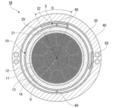
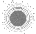
- 1 is an example of a cross-sectional view of the optical fiber cable according to the first embodiment. It is an example of the cross-sectional view of the optical fiber cable based on 2nd Embodiment. It is an example of the cross-sectional view of the optical fiber cable based on 3rd Embodiment. It is an example of the cross-sectional view of the optical fiber cable based on 4th Embodiment. It is an example of the cross-sectional view of the optical fiber cable based on the modification of 4th Embodiment. It is an example of the cross-sectional view of the optical fiber cable based on 5th Embodiment.
- the optical fiber cable 1A includes a core 10 having an optical fiber 11, a regulating member 20 covering the core 10, a reinforcing member 30, a sheath 40, four tensile strength members 50, and two It is equipped with a rip cord 60.
- the longitudinal direction of the core 10 is simply referred to as the longitudinal direction
- the central axis of the core 10 is simply referred to as the central axis O.
- a cross section perpendicular to the central axis O is called a cross section.
- the direction that intersects with the central axis O is called the radial direction
- the direction that goes around the central axis O is called the circumferential direction.
- the core 10 includes a plurality of optical fibers 11, a plurality of bundle materials 12, a water-absorbing tape 13, and an inner sheath 14.
- Each bundle material 12 binds a plurality of optical fibers 11 together.
- the core 10 includes a total of 12 optical fiber units each consisting of an optical fiber 11 and a bundle material 12.
- the water-absorbing tape 13 wraps these optical fiber units.
- the water-absorbing tape 13 is made of a water-absorbing material and has the role of preventing water from running inside the core 10 .
- the inner sheath 14 has a cylindrical shape extending in the longitudinal direction, and covers the water absorbing tape 13.
- resins such as polyethylene (PE) and polyvinyl chloride (PVC) can be used.
- the core 10 in the example of FIG. 1 has three optical fiber units forming an inner layer and nine optical fiber units forming an outer layer.
- the cross-sectional shape of the core 10 may not be uniform as shown in FIG. 1, and the optical fiber unit may not be divided into an inner layer and an outer layer.
- the bundle material 12, the water-absorbing tape 13, and the internal sheath 14 may be omitted. That is, the optical fiber 11 does not need to constitute an optical fiber unit.
- the number of optical fibers 11 disposed in the core 10 is not limited to a plurality of fibers, and may be one.
- the core 10 may be composed of only one optical fiber 11.
- the reinforcing member 30 is a cylindrical member that extends in the longitudinal direction and surrounds the core 10 and the regulating member 20.
- the reinforcing member 30 may be configured by forming a sheet-like member into a cylindrical shape surrounding the core 10 and the regulating member 20.
- metal iron, stainless steel, copper, copper alloy, etc.
- the thickness of the reinforcing member 30 is, for example, about 0.1 to 0.3 mm.
- the thickness of the reinforcing member 30 By setting the thickness of the reinforcing member 30 within this range, it is possible to prevent the optical fiber of the core 10 from being damaged due to eating damage by animals, etc., and to facilitate the operation of tearing the reinforcing member 30 with the rip cord 60. .
- the reinforcing member 30 may not be provided. The presence or absence of the reinforcing member 30 may be selected depending on, for example, the specifications of the optical fiber cable 1A or the location where it is installed.
- the reinforcing member 30 surrounds the entire circumference of the core 10 and may be partially overlapped in the circumferential direction.
- the portion where the reinforcing members 30 are overlapped is called an overlapping portion 30a.
- the strength of the overlapping portion 30a is high. Therefore, it is more difficult to tear the reinforcing member 30 with the rip cord 60 at the overlapped portion 30a than at other parts of the reinforcing member 30.
- the overlapping portion 30a and the rip cord 60 are arranged apart from each other in the circumferential direction.
- adhesive layers may be provided on both sides of the reinforcing member 30.
- the reinforcing member 30 can be adhesively fixed to the sheath 40 using an adhesive layer, and the ends of the reinforcing member 30 can be adhesively fixed to each other at the overlapped portion 30a.
- the adhesive layer may not be provided on one or both surfaces of the reinforcing member 30.
- the reinforcing member 30 surrounds the entire circumference of the core 10.
- the core 10 may be surrounded by the reinforcing member 30 by the edges 31 of the reinforcing member 30 coming into contact with each other in a cross-sectional view without forming the overlapping part 30a.
- the edges 31 of the reinforcing member 30 may be adhesively fixed to each other.
- the sheath 40 accommodates the core 10, the regulating member 20, the rip cord 60, and the reinforcing member 30.
- the sheath 40 is formed into a cylindrical shape extending in the longitudinal direction.
- resins such as polyethylene (PE) and polyvinyl chloride (PVC) can be used.
- two tensile strength members 50 are used as a set, and the two sets of tensile strength members 50 (that is, four in total) are embedded in the sheath 40 so as to sandwich the core 10 in a cross-sectional view.
- a plurality of tensile strength members 50 that form one set are also referred to as a tensile strength member group. That is, the optical fiber cable 1A has a pair of tensile strength bodies arranged within the sheath 40 with the core 10 in between. Each tensile strength body 50 extends in the longitudinal direction parallel to the core 10. The tensile strength body 50 has a role of protecting the optical fiber 11 from the tension acting on the optical fiber cable 1A.
- the material of the tensile strength body 50 is, for example, a metal wire (such as a steel wire), a tensile strength fiber (such as an aramid fiber), or FRP.
- the tensile strength body 50 may be a single wire, or may be a wire made by bundling or twisting a plurality of wires together.
- the optical fiber cable 1A Due to the arrangement of the tensile strength member 50, the optical fiber cable 1A has bending directionality. Specifically, the optical fiber cable 1A is easy to bend in a direction perpendicular to the neutral line L (see FIG. 1), and difficult to bend in a direction parallel to the neutral line L.
- the midpoints of the tensile strength member group including two adjacent tensile strength members 50 are defined at two locations. The straight line connecting the midpoints of these two locations becomes the neutral line L.
- the neutral line L may pass through the central axis O. Note that the number and arrangement of the tensile strength members 50 can be changed as appropriate.
- one tensile strength body group includes two tensile strength bodies 50
- the number of tensile strength bodies included in one tensile strength body group may be one or three or more.
- the tensile strength member 50 may be arranged so that no bending directionality occurs (that is, so that the neutral line L is not defined). Further, the tensile strength body 50 may not be embedded in the sheath 40 but may be disposed within the core 10. Alternatively, the optical fiber cable 1A may not include the tensile strength member 50.
- the rip cord 60 is used when tearing the reinforcing member 30 and the sheath 40 (hereinafter simply referred to as tearing work).
- the rip cord 60 is required to have sufficient mechanical strength (for example, tensile strength) to cut through the reinforcing member 30 and the sheath 40.
- tensile strength As the rip cord 60, thread (yarn) made by twisting together fibers such as PP (polypropylene) and polyester can be used.
- the tensile strength member 50 has the role of protecting the optical fiber 11 from tension, while the rip cord 60 has the role of tearing the sheath 40. Therefore, the rip cord 60 and the tensile strength member 50 are made of different materials. Specifically, the tensile elastic modulus of the tensile strength body 50 is larger than that of the rip cord 60. Furthermore, the rip cord 60 is more flexible than the tensile strength member 50.
- the two ripcords 60 are arranged so that the core 10 is sandwiched between them in a cross-sectional view. According to this arrangement, when the reinforcing member 30 and the sheath 40 are torn apart using the two rip cords 60, the reinforcing member 30 and the sheath 40 can be divided into two parts. Therefore, it becomes easy to take out the core 10 from inside the sheath 40.
- the two rip cords 60 and the central axis O are located in a straight line in a cross-sectional view, and the straight line connecting the two rip cords 60 and the neutral line L are as follows. Orthogonal. This prevents the rip cord 60 from hitting the tensile strength member 50 when tearing the sheath 40, making it easier to divide the sheath 40 into semi-cylindrical sections. However, even if the two rip cords 60 and the central axis O are not aligned, it is possible to tear the sheath 40 and take out the core 10.
- the rip cord 60 and the tensile strength member 50 may be arranged at different positions in the circumferential direction so that the rip cord 60 does not hit the tensile strength member 50 when tearing the sheath 40. Further, the number of rip cords 60 does not need to be two, and may be one or three or more. Even if there is only one ripcord 60, it is possible to tear the sheath 40 and take out the core 10.
- the sheath 40 may be provided with a mark to indicate the position of the rip cord 60.
- the mark may be, for example, a colored portion provided on the outer circumferential surface of the sheath 40, a groove recessed from the outer circumferential surface of the sheath 40, or a protrusion protruding from the outer circumferential surface. Further, the operator may grasp the position of the rip cord 60 based on the bending directionality of the optical fiber cable 1A. In this case, a mark indicating the position of the rip cord 60 is not necessary.
- the sheath 40 and reinforcing member 30 are partially cut open using a tool such as a cutter.
- a tool such as pliers is inserted through the cut portion, grips the rip cord 60, and pulls it out of the sheath 40.
- the reinforcing member 30 and the sheath 40 are torn apart by the rip cord 60 extending in the longitudinal direction, and the core 10 can be taken out.
- the optical fiber 11 can be taken out.
- an annular gap for arranging the rip cord 60 is provided outside the core 10 and inside the sheath 40 (in this embodiment, between the reinforcing member 30 and the core 10). If the rip cord 60 moves in the circumferential direction within this gap, it will take time for the operator to find the rip cord 60, which may reduce work efficiency. Furthermore, when the rip cord 60 moves and approaches the overlapped portion 30a of the reinforcing member 30, the strong overlap portion 30a may not be torn, or the ripcord 60 may come into contact with the edge 31 and break. This may cause a decrease in workability.
- the regulating member 20 is provided to suppress movement of the rip cord 60 in the circumferential direction.
- the regulating member 20 may be, for example, a water-absorbing sheet (press-wrapped sheet, etc.). In this case, the regulating member 20 also makes it possible to improve the waterproof performance of the optical fiber cable 1A.
- the material of the regulating member 20 may be the same as that of the water-absorbing tape 13, or may be different. Examples of the material of the regulating member 20 include a fibrous inclusion, a member made of the same material as the reinforcing member 30, an adhesive, a resin sheet, or a nonwoven fabric. When the regulating member 20 is an adhesive, the sheath 40 and the core 10 may be bonded together by the regulating member 20.
- the regulating member 20 is attached vertically to the core 10. Further, the regulating member 20 is in the form of a sheet, and is wound around the core 10 .
- the regulating member 20 has a C-shape in a cross-sectional view, and does not cover the core 10 in a part of the circumferential direction.
- W is the outer circumferential dimension of the core 10. is smaller than ⁇ Dc.
- the region S is provided between both ends of the regulating member 20 in the circumferential direction.
- the regulating member 20 has a first portion 21 that is a part of the regulating member 20 , and a second portion 22 that is a part of the regulating member 20 that is different from the first portion 21 .
- the region S is provided between the first portion 21 and the second portion 22.
- both ends of the regulating member 20 in the circumferential direction are defined as a first portion 21 and a second portion 22.
- a rip cord 60 is arranged between the first portion 21 and the second portion 22. That is, the rip cord 60 is sandwiched between the first portion 21 and the second portion 22. When the rip cord 60 attempts to move in the circumferential direction, the rip cord 60 comes into contact with the first portion 21 or the second portion 22, so such movement is suppressed.
- the first part 21 and the second part 22 are separated from the overlapping part 30a of the reinforcing member 30 in the circumferential direction. It is arranged as follows. That is, in the circumferential direction, the region S and the overlapping portion 30a of the reinforcing member 30 are arranged at different positions from each other. This can prevent the edge 31 of the reinforcing member 30 and the rip cord 60 from coming into contact with each other, thereby preventing the rip cord 60 from being damaged or cut by the edge 31 of the reinforcing member 30.
- the overlapping part 30a of the reinforcing member 30 is arranged in a range of ⁇ 45° from the neutral line L around the central axis O, and the overlapping part 30a of the reinforcing member 30 and the region S are at different positions in the circumferential direction. may be placed. In this case, contact between the edge 31 of the reinforcing member 30 and the rip cord 60 can be more reliably prevented.
- a plurality of regions S may be provided in consideration of the number and arrangement of the rip cords 60, etc.
- a plurality of regions S may be provided using a plurality of regulating members 20, and the plurality of regulating members 20 may be made of different materials.
- the core 10 and the regulating member 20 may be fixed by adhesive. In this case, it is possible to prevent the rip cord 60 from entering between the core 10 and the regulating member 20.
- the core 10 is prepared (first step).
- a sheet serving as the regulating member 20 is attached vertically to the core 10 (second step). More specifically, the regulating member 20 is wound around the core 10 from below in the direction of gravity.
- the width W of the sheet (the dimension in the direction orthogonal to the longitudinal direction of the core 10) is made shorter than the outer circumferential dimension ⁇ Dc of the core 10.
- the upper portion of the core 10 in the direction of gravity is not covered by the regulating member 20, and the first portion 21 and the second portion 22 of the regulating member 20 face each other in this portion.
- two rip cords 60 are attached vertically to the core 10 and the regulating member 20. More specifically, one rip cord 60 is placed between the first portion 21 and the second portion 22. Further, the remaining rip cord 60 is attached vertically to the regulating member 20 from below in the direction of gravity.
- the core 10, the regulating member 20, and the rip cord 60 are wrapped with the reinforcing member 30 (third step).
- a sheath 40 is formed around the reinforcing member 30 by, for example, extrusion molding (fourth step). As a result, an optical fiber cable 1A is obtained.
- the rip cord 60 placed above the core 10 in the direction of gravity may tend to move in the circumferential direction due to the influence of gravity.
- the movement of the rip cord 60 is suppressed by the rip cord 60 coming into contact with the first portion 21 or the second portion 22. Therefore, the optical fiber cable 1A in which the rip cord 60 is arranged at a predetermined position can be manufactured more easily.
- the rip cord 60 disposed below the core 10 in the gravity direction is located at the lowest part of the gap between the regulating member 20 and the reinforcing member 30. Therefore, even if the rip cord 60 is not restrained from moving by the regulating member 20, movement in the circumferential direction is unlikely to occur, and it can be easily placed at a predetermined position.
- the rip cord 60 disposed below the core 10 in the gravity direction may be disposed in the region S formed between the first portion 21 and the second portion 22 of the regulating member 20. Further, the regions S are provided in two places, and both of the rip cords 60 disposed above the core 10 in the direction of gravity and the rip cords 60 disposed below the first portion 21 of the regulating member 20 and the second portion 22.
- the optical fiber cable 1A of the present embodiment includes a core 10 having an optical fiber 11, a regulating member 20 that is longitudinally attached to the core 10 and covers the core 10, and a sheath 40 that covers the regulating member 20.
- a rip cord 60 is provided between the sheath 40 and the core 10, and the rip cord 60 is located between the first portion 21 and the second portion 22 of the regulating member 20.
- the optical fiber cable 1A further includes a reinforcing member 30 disposed between the regulating member 20 and the sheath 40. Thereby, it is possible to prevent the optical fiber 11 of the core 10 from being damaged due to eating damage by animals or the like.
- the optical fiber cable 1A further includes a tensile strength member 50 disposed within the sheath 40, and the rip cord 60 and the tensile strength member 50 are disposed at different positions in the circumferential direction in a cross-sectional view. This provides a positional relationship in which the rip cord 60 does not hit the tensile strength member 50 when tearing the sheath 40, and the tearing operation can be performed more easily.
- the rip cord 60 is located between the first portion 21 and the second portion 22 over the entire length of the optical fiber cable 1A in the longitudinal direction. In this case, movement of the rip cord 60 can be more reliably regulated. However, if the ripcord 60 is located between the first portion 21 and the second portion 22 in at least one cross section, the position of the ripcord 60 is restricted at that location. The effects of movement restrictions can be spread throughout the entire length. Therefore, it is not essential that the rip cord 60 be located between the first portion 21 and the second portion 22 over the entire length in the longitudinal direction.
- the optical fiber cable 1A includes a plurality of ripcords 60
- at least one ripcord 60 among the plurality of ripcords 60 is located between the first portion 21 and the second portion 22. All you have to do is do it.
- one ripcord 60 is disposed between the first portion 21 and the second portion 22, and the other ripcord 60 is located in the first portion. 21 and the second portion 22, but may be arranged between the regulating member 20 and the reinforcing member 30.
- the aspect of the first portion 21 and the second portion 22 that sandwich the rip cord 60 is different from that of the first embodiment.
- the regulating member 20 covers the entire circumference of the core 10. Further, both ends of the regulating member 20 in the circumferential direction are overlapped.
- the total circumferential length W of the regulating member 20 is larger than ⁇ Dc, which is the outer circumferential dimension of the core 10.
- the rip cord 60 is sandwiched between the circumferentially overlapping portions of both ends of the regulating member 20 .
- the first portion 21 and the second portion 22, which are both ends of the regulating member 20, are arranged to overlap in the radial direction, and the rip cord 60 is sandwiched in the radial direction.
- a region S is provided between the first portion 21 and the second portion 22, and the rip cord 60 is arranged in the region S.
- the width in the circumferential direction of the portion where the first portion 21 and the second portion 22 overlap is defined as an overlap width D.
- the rip cord 60 is arranged within an overlap width D in the circumferential direction. Even in the case of such a configuration, the same effects as in the first embodiment can be obtained.
- the aspect of the first portion 21 and the second portion 22 that sandwich the rip cord 60 is different from that of the first embodiment.
- the total circumferential length W of the regulating member 20 is larger than ⁇ Dc, which is the outer circumferential dimension of the core 10, and the regulating member 20 is formed with a folded portion 20a.
- the folded portion 20a is, for example, a portion where one end in the circumferential direction of the regulating member 20 is folded back.
- the folded portion 20a has a bent portion 20b where the regulating member 20 is bent, and an opening 20c in a region S that accommodates the rip cord 60.
- the folded portion 20a may be provided at the middle portion of the regulating member 20 in the circumferential direction.
- a rip cord 60 is sandwiched between two opposing surfaces of the folded portion 20a. These two opposing surfaces are the surface of the first portion 21 and the surface of the second portion 22, respectively.
- the two opposing surfaces of the folded portion 20a are a radially outward facing surface of the first portion 21 and a radially outward facing surface of the second portion 22 that is disposed radially outward from the first portion 21. This is the side facing inward.
- the folded portion 20a is composed of the first portion 21 and the second portion 22 that sandwich the rip cord 60 therebetween.
- This embodiment is common to the second embodiment in that the first portion 21 and the second portion 22 sandwich the rip cord 60 in the radial direction. Even in the case of such a configuration, the same effects as in the first embodiment can be obtained.
- the width in the circumferential direction of the portion where the first portion 21 and the second portion 22 overlap is defined as an overlap width D.
- the rip cord 60 is arranged at the center of the overlap width D. Note that the rip cord 60 only needs to be disposed within the folded portion 20a in the circumferential direction.
- the rip cord 60 may be placed in the region S so as to be in contact with the bent portion 20b, or may be placed near the opening 20c.
- the regulating member 20 has an end portion of the regulating member 20 where the folded portion 20a is provided, and an end portion 23 of the regulating member 20 on the opposite side to the end portion.
- the end portion 23 is not provided with a folded portion.
- the end portion 23 is arranged radially inside the folded portion 20a. In the circumferential direction, the edge of the end portion 23 is arranged at the same position as the opening 20c of the folded portion 20a, but the present invention is not limited to this example. may be placed within the range of
- the core 10 is prepared.
- a sheet that will become the regulating member 20 is attached vertically to the core 10 .
- the regulating member 20 is wound around the core 10 from below in the direction of gravity.
- the first part 21 and the second part 22 of the regulating member 20 are made to face each other, and the folded part 20a is formed.
- the rip cord 60 is placed inside the folded portion 20a.
- two ripcords 60 are provided, one ripcord 60 is placed between the first part 21 and the second part 22, and the remaining ripcord 60 is inserted into the regulating member from below in the direction of gravity. It may be attached vertically to 20.
- the reinforcing member 30 and the sheath 40 are provided in the same manner as in the method for manufacturing the optical fiber cable 1A of the first embodiment, thereby obtaining the optical fiber cable 1C.
- the method for manufacturing the optical fiber cable 1C in this embodiment includes the first step of preparing the core 10 having the optical fiber 11, the second step of winding the regulating member 20 around the core 10, and the second step of winding the regulating member 20 around the core 10. a third step of covering the core 10 having a reinforcing member 30 with a reinforcing member 30; and a fourth step of covering the reinforcing member 30 with a sheath 40.
- a rip cord 60 is placed inside 20a.
- the rip cord 60 is fed into the manufacturing line while being given a predetermined tension. Due to the tension applied to the rip cord 60, the rip cord 60 is fed into the manufacturing line at a stable position within the manufacturing line, so that the rip cord 60 can be reliably placed inside the folded portion 20a.
- the regulation member 20 includes a first regulation member 201 and a second regulation member 202.
- the first regulating member 201 and the second regulating member 202 are wound around the core 10, and one end 201a of the first regulating member 201 and one end 202a of the second regulating member 202 that are adjacent to each other in the circumferential direction.
- a folded portion 20a is provided at one end.
- folded parts 20a are provided at both ends 201a of the first regulating member 201, and the first regulating member 201 and the second regulating member 202 cover the entire circumference of the core 10. .
- the total length of the first regulating member 201 in the circumferential direction (i.e., the width of the first regulating member 201 before being wound around the core 10) in the cross-sectional view is W1
- the total length of the second regulating member 202 in the circumferential direction i.e., the width of the first regulating member 201 before being wound around the core 10.
- the width of the second regulating member 202 before being wrapped around the second regulating member 202 is defined as W2.
- W1 is larger than W2, and W1 is larger than 1/2 of ⁇ Dc, which is the outer peripheral dimension of the core 10.
- the second regulating member 202 is arranged closer to the overlapping portion 30a of the reinforcing member 30.
- a folded portion 20a is formed at each end 201a of the first regulating member 201 in the circumferential direction.
- the folding parts 20a each have the same configuration as the folding part 20a described in the third embodiment, so the same reference numerals are given and the description thereof will be omitted.
- the two folded parts 20a of the first regulating member 201 are respectively referred to as a first folded part 20a1 and a second folded part 20a2.
- the first folded portion 20a1 and the second folded portion 20a2 are arranged so as to sandwich the core 10 therebetween in a cross-sectional view.
- the overlap width D of the first folded portion 20a1 is set to D1
- the overlap width D of the second folded portion 20a2 is set to D2.
- D1 and D2 may be equivalent or different from each other.
- the rip cord 60 is arranged in a region S within the folded portion 20a so as to be in contact with the bent portion 20b. Note that the rip cord 60 only needs to be disposed within the folded portion 20a in the circumferential direction.
- the plurality of folded portions 20a and the overlapping portions 30a of the reinforcing member 30 are arranged at different positions in the circumferential direction.
- a straight line connecting the center portion W1m of the total circumferential length W1 of the first regulating member 201 and the center portion W2m of the circumferential total length W2 of the second regulating member 202 is the overlapped portion 30a of the reinforcing member 30.
- the overlapping portion 30a may be arranged so as to intersect with. In this case, it is possible to more reliably prevent both of the two rip cords 60 from being damaged or cut by the edge 31 of the reinforcing member 30.
- the center portion W1m and the center portion W2m are located on the neutral line L, but the present invention is not limited to this example, and the center portion W1m and the center portion W2m do not need to be on the neutral line L.
- the bent portion 20b is arranged between the opening 20c and the overlapping portion 30a of the end portions of the reinforcing member 30.
- the end portion 202a of the second regulating member 202 is not provided with a folded portion 20a.
- the end portions 202a are each arranged radially inside the folded portion 20a.
- the edge of the end portion 202a is arranged at the same position as the opening 20c of the folded portion 20a in the circumferential direction. However, the edge of the end portion 202a may be arranged within the range of the overlapping width D of the folded portion 20a in the circumferential direction.
- the overlapping part 30a of the reinforcing member 30 is arranged in a range of ⁇ 45° from the neutral line L around the central axis O, and the overlapping part 30a of the reinforcing member 30 and the first regulating member 201
- the center portion W1m of W1 may be arranged at a distance of 45° or more from the center axis in the circumferential direction. In this case, contact between the edge 31 of the reinforcing member 30 and the rip cord 60 can be more reliably prevented.
- the method for manufacturing the optical fiber cable 1D is basically the same as the method for manufacturing the optical fiber cable 1C in the third embodiment. Therefore, only the different points will be explained. However, other manufacturing methods may be adopted.
- Two sheets, which will become the first regulating member 201 and the second regulating member 202, are attached vertically to the prepared core 10.
- first the second regulating member 202 is placed on the side surface of the core 10 from the right side of the core 10
- the first regulating member 201 is placed on the side surface of the core 10 from the left side of the core 10. Place it on the side.
- the ends 201a of the first regulating member 201 are arranged to overlap both ends 202a of the second regulating member 202.
- Two folded portions 20a are formed by bending the ends 201a of the first regulating member 201 at locations where the first regulating member 201 and the second regulating member 202 overlap.
- the rip cord 60 When bending the end portion 201a of the first regulating member 201, the rip cord 60 is placed inside the folded portion 20a. More specifically, the rip cord 60 is arranged on the outer peripheral surface of the end 201a of the first regulating member 201, and the first regulating member 201 is bent at the location where the rip cord 60 is arranged, and the first regulating member 201 is bent at the bent part 20b. The first portion 21 and the second portion 22 are opposed to each other with the rip cord 60 in contact with each other. Since a predetermined tension is applied to the rip cord 60 during the manufacturing line, the folded portion 20a can be formed while pressing the rip cord 60 against the portion that will become the bent portion 20b.
- the end portion 202a of the second regulating member 202 is arranged radially inside the first regulating member 201, and the entire circumference of the core 10 is covered by the regulating member 20. Therefore, it is possible to prevent the first regulating member 201 and the second regulating member 202 from moving within the space between the core 10 and the reinforcing member 30.
- the folded part 20a where the first part 21 and the second part 22 face each other has a bent part 20b where the regulating member 20 is bent and a rip cord 60.
- the reinforcing member 30 has an opening 20c in the accommodated region S, and a bent portion 20b is arranged between the opening 20c and the overlapping portion 30a of the end portions of the reinforcing member 30 in the circumferential direction.
- the regulation member 20 includes a first regulation member 201 and a second regulation member 202, and a folded part where the first part 21 and the second part 22 face each other at both ends 201a of the first regulation member 201 in the circumferential direction. 20a are formed respectively. Thereby, the workability of taking out the core 10 using the rip cords 60 respectively arranged on the folded portions 20a can be performed satisfactorily.
- the regulating member 20 does not cover the entire circumference of the core 10. More specifically, this embodiment differs from the fourth embodiment in that the end portion 202a of the second regulating member 202 does not overlap the folded portion 20a of the first regulating member 201. As shown in FIG. 5, a gap is provided between the first regulating member 201 and the second regulating member 202. By arranging the second regulating member 202, it is possible to prevent the folded portion 20a from moving to a position where it overlaps the overlapping portion 30a of the reinforcing member 30 in the circumferential direction.
- the outer diameter of the optical fiber cable 1D can be made thinner.
- the first regulating member 201 may be placed on the outer peripheral surface of the core 10 first.
- the optical fiber cable 1E of this embodiment differs from the fourth embodiment in that each of the first regulating member 201 and the second regulating member 202 is provided with one folded portion 20a.
- the first folded part 20a1 provided on the first regulation member 201 and the second folded part 20a2 provided on the second regulation member 202 are arranged so as to sandwich the core 10 therebetween in a cross-sectional view.
- An end portion 202a of the second regulating member 202 on which the second folded portion 20a2 is not formed is arranged radially inside the first folded portion 20a1 provided on the first regulating member 201.
- An end portion 201a of the first regulating member 201 on which the first folded portion 20a1 is not formed is arranged radially inside the second folded portion 20a2 provided on the second regulating member 202.
- the first regulating member 201 and the second regulating member 202 cover the entire circumference of the core 10, but there is a gap between the first regulating member 201 and the second regulating member 202 in the circumferential direction. may be provided.
- the total circumferential length W1 of the first regulating member 201 and the total circumferential length W2 of the second regulating member 202 may be the same or different from each other.
- a straight line connecting the center portion W1m of the total circumferential length W1 of the first regulating member 201 and the center portion W2m of the circumferential total length W2 of the second regulating member 202 is the overlapped portion 30a of the reinforcing member 30.
- the overlapping portion 30a may be arranged so as to intersect with.
- the bent portion 20b is arranged between the opening 20c and the overlapping portion 30a of the end portions of the reinforcing member 30 in the circumferential direction.
- the first regulating member 201 is arranged, so that the ripcord 60 can be moved between the regulating member 20 and the core 10. This can prevent it from getting in between. Therefore, the operator can discover the rip cord 60 more easily.
- the second folded part 20a2 is arranged so that the edge 31 of the reinforcing member 30 and the rip cord 60 are unlikely to come into contact even when the rip cord 60 moves and comes out of the second folded part 20a2.
- the length between the first folded portion 20a1 and the overlapped portion 30a may be longer than the length between the first folded portion 20a1 and the overlapped portion 30a.
- the method for manufacturing the optical fiber cable 1E is the method for manufacturing the optical fiber cable 1D described in the fourth embodiment, in which the end portion of the regulating member 20 where the folded portion 20a is formed is on the outside in the radial direction.
- the difference is that two regulating members 201 and 202 are arranged on the side surface of the core 10, and one end 201a of the first regulating member 201 and one end 202a of the second regulating member 202 arranged on the radially outer side are respectively bent.
- they are basically the same.
- the same effects as in the method for manufacturing the optical fiber cable 1D described in the fourth embodiment can be obtained.
- other manufacturing methods may be adopted.
- the regulation member 20 includes the first regulation member 201 and the second regulation member 202, and the one end 201a of the first regulation member 201 and the second regulation member 202.
- a folded portion 20a where the first portion 21 and the second portion 22 face each other is formed at one end portion 202a, and the end portion 201a of the first regulating member 201 and the second regulating member 202 that are adjacent to each other in the circumferential direction are formed.
- a folded portion 20a is provided on either one of the end portions 202a.
- Example 1 Corresponding to the first embodiment, an optical fiber cable 1A having 144 intermittent fixed tape cores was created. Each intermittent fixed tape cable core has 12 optical fibers 11 and a connecting portion that connects these optical fibers 11 intermittently. That is, the optical fiber cable 1A in Example 1 has a total of 1728 optical fibers 11.
- a water-absorbing tape with a width of 60 mm that is, a circumferential length in a cross-sectional view of 60 mm
- the diameter of the rip cord 60 was 1.0 mm.
- the ratio of the area of the outer peripheral surface of the core 10 (in the example of FIG. 1, the outer peripheral surface of the inner sheath 14) that is not covered by the regulating member 20 is expressed as an aperture ratio R1 (%).
- opening width is the length in the circumferential direction of the area of the outer peripheral surface of the core 10 that is not covered by the regulating member 20.
- opening width/rip cord diameter is a value obtained by dividing the opening width by the diameter of the rip cord 60.
- the “core removal workability” in Table 1 shows that for each of the prepared samples, if the ripcord 60 breaks when tearing the reinforcing member 30 and the sheath 40 using the ripcord 60, the “core removal workability” ⁇ sexuality'' was rejected.
- “Waterproof properties” in Table 1 shows the results of a waterproof test performed on each sample. Specifically, for each sample with a length of 3 m, “water penetration” (tap water, sample length 3 m, head The test was conducted under the following conditions (1 m long, with orifice, no pre-soak), and the case where water flow occurred over the entire length of the sample was judged as NG.
- the aperture ratio R1 is preferably 35% or less, more preferably 30% or less.
- the lower limit value of the aperture ratio R1 is not particularly limited as long as the rip cord 60 can be placed between the first portion 21 and the second portion 22.
- the opening width is preferably larger than the ripcord diameter.
- an optical fiber cable 1C having 144 intermittent fixed tape cores was created.
- Each intermittent fixed tape cable core has 12 optical fibers 11 and a connecting portion that connects these optical fibers 11 intermittently. That is, the optical fiber cable 1C in Example 2 has a total of 1728 optical fibers 11.
- a water-absorbing tape with a width of 60 mm that is, a circumferential length in a cross-sectional view of 60 mm was used.
- the diameter of the rip cord 60 was 1.0 mm.
- the overlap width D/rip cord diameter is 5.0 or more.
- a case where the first portion 21 and the second portion 22 are folded portions 20a as shown in FIG. 3 was examined.
- the effect of setting the overlap width D/rip cord diameter to 5.0 or more is the same even when the first portion 21 and the second portion 22 are at both ends of the regulating member 20, as shown in FIG. It is thought that it can be obtained.
- the overlap width D in FIG. 2 can also be defined in the same way as the overlap width D in FIG.
- Example 3 An optical fiber cable 1D having 24 intermittent fixed tape cores corresponding to the optical fiber cable 1D shown in FIG. 4 of the fourth embodiment was created.
- Each intermittent fixed tape cable core has 12 optical fibers 11 and a connecting portion that connects these optical fibers 11 intermittently. That is, the optical fiber cable 1D in Example 3 has 288 optical fibers 11 in total.
- the outer diameter Dc of the core 10 the total length W1 in the circumferential direction of the first regulating member 201, the total length W2 in the circumferential direction of the second regulating member 202, and the outer diameter Dr of the rip cord 60 are expressed by the following formula (2). (4) is satisfied. ⁇ Dc/2 ⁇ W1...(2) W1>W2...(3) Dr ⁇ D1 and Dr ⁇ D2 (4)
- the optical fiber cables 1A to 1E do not need to be provided with the reinforcing member 30. Even when there is no reinforcing member 30, there may be a problem that when the rip cord 60 moves in the circumferential direction, the operator cannot find the rip cord 60, resulting in reduced work efficiency. In other words, the configuration of the present disclosure is effective even in an optical fiber cable without the reinforcing member 30.
- the thickness of both ends of the regulating member 20 in the circumferential direction i.e., the thickness of the first portion 21 and the second portion 22
- the thickness of both ends of the regulating member 20 in the circumferential direction may be larger than the thickness of other parts of the regulating member 20.
- the rip cord 60 is prevented from climbing over the first portion 21 and the second portion 22 in the circumferential direction, and the movement of the rip cord 60 can be more reliably regulated.
- the bent portion 20b, the opening 20c, and the overlapping portion 30a are arranged in this order in the circumferential direction, but the opening 20c, the bent portion 20b , and the overlapping portion 30a may be arranged in this order.
- the rip cord 60 disposed in the folded portion 20a moves outside from the opening 20c, the rip cord 60 is prevented from coming into contact with the edge 31 of the reinforcing member 30. I can do it.
- first portion 21 and the second portion 22 of the regulating member 20 may be in direct contact with each other in the region S.
- the size of these openings may be smaller than the outer diameter Dr of the rip cord 60.
- the regulating member 20 does not need to cover the entire circumference of the core 10.
- a gap may be provided between two circumferentially adjacent regulating members 20.
Landscapes
- Physics & Mathematics (AREA)
- General Physics & Mathematics (AREA)
- Optics & Photonics (AREA)
- Light Guides In General And Applications Therefor (AREA)
- Insulated Conductors (AREA)
Priority Applications (5)
| Application Number | Priority Date | Filing Date | Title |
|---|---|---|---|
| CN202380024925.7A CN118805108A (zh) | 2022-03-14 | 2023-02-20 | 光纤线缆以及光纤线缆的制造方法 |
| EP23770278.2A EP4495653A4 (en) | 2022-03-14 | 2023-02-20 | FIBER OPTIC CABLE AND FIBER OPTIC CABLE PRODUCTION METHOD |
| JP2024507634A JPWO2023176319A1 (https=) | 2022-03-14 | 2023-02-20 | |
| CA3245683A CA3245683A1 (en) | 2022-03-14 | 2023-02-20 | FIBER OPTIC CABLE AND FIBER OPTIC CABLE PRODUCTION METHOD |
| US18/846,542 US20250216637A1 (en) | 2022-03-14 | 2023-02-20 | Optical fiber cable and production method for optical fiber cable |
Applications Claiming Priority (2)
| Application Number | Priority Date | Filing Date | Title |
|---|---|---|---|
| JP2022-039603 | 2022-03-14 | ||
| JP2022039603 | 2022-03-14 |
Publications (1)
| Publication Number | Publication Date |
|---|---|
| WO2023176319A1 true WO2023176319A1 (ja) | 2023-09-21 |
Family
ID=88023401
Family Applications (1)
| Application Number | Title | Priority Date | Filing Date |
|---|---|---|---|
| PCT/JP2023/005994 Ceased WO2023176319A1 (ja) | 2022-03-14 | 2023-02-20 | 光ファイバケーブルおよび光ファイバケーブルの製造方法 |
Country Status (7)
| Country | Link |
|---|---|
| US (1) | US20250216637A1 (https=) |
| EP (1) | EP4495653A4 (https=) |
| JP (1) | JPWO2023176319A1 (https=) |
| CN (1) | CN118805108A (https=) |
| CA (1) | CA3245683A1 (https=) |
| TW (1) | TWI853459B (https=) |
| WO (1) | WO2023176319A1 (https=) |
Cited By (1)
| Publication number | Priority date | Publication date | Assignee | Title |
|---|---|---|---|---|
| EP4459346A3 (en) * | 2023-05-05 | 2025-02-26 | Sterlite Technologies Limited | Optical fiber cable with metal armoring |
Families Citing this family (1)
| Publication number | Priority date | Publication date | Assignee | Title |
|---|---|---|---|---|
| US8913862B1 (en) * | 2013-09-27 | 2014-12-16 | Corning Optical Communications LLC | Optical communication cable |
Citations (7)
| Publication number | Priority date | Publication date | Assignee | Title |
|---|---|---|---|---|
| JP2004191504A (ja) * | 2002-12-09 | 2004-07-08 | Fujikura Ltd | 光ケーブル |
| JP2013228647A (ja) * | 2012-04-27 | 2013-11-07 | Furukawa Electric Co Ltd:The | 光ファイバケーブル |
| WO2017061196A1 (ja) * | 2015-10-09 | 2017-04-13 | 株式会社フジクラ | 光ファイバケーブル |
| WO2019124157A1 (ja) * | 2017-12-21 | 2019-06-27 | 株式会社フジクラ | 光ファイバケーブル |
| EP3514593A1 (en) * | 2018-01-23 | 2019-07-24 | Sterlite Technologies Limited | Flexible central tube ribbon optical fiber cable |
| WO2022004666A1 (ja) * | 2020-06-29 | 2022-01-06 | 住友電気工業株式会社 | 光ファイバケーブル |
| JP2022039603A (ja) | 2020-08-28 | 2022-03-10 | 日亜化学工業株式会社 | 発光装置及びその製造方法 |
Family Cites Families (13)
| Publication number | Priority date | Publication date | Assignee | Title |
|---|---|---|---|---|
| US5173961A (en) * | 1991-12-12 | 1992-12-22 | Northern Telecom Limited | Telecommunications cable with ripcord removal for metal sheath |
| US7664354B2 (en) * | 2006-08-01 | 2010-02-16 | Nexans | System and method for loose tube tight buffer indoor/outdoor optical fiber cable |
| JP2014119635A (ja) * | 2012-12-18 | 2014-06-30 | Sumitomo Electric Ind Ltd | 光ケーブル |
| JP6549828B2 (ja) * | 2014-10-16 | 2019-07-24 | 古河電気工業株式会社 | 光ファイバケーブルおよびその製造方法 |
| JP6542648B2 (ja) * | 2015-11-20 | 2019-07-10 | 住友電気工業株式会社 | 光ファイバケーブル |
| JP6298503B2 (ja) * | 2016-08-04 | 2018-03-20 | 株式会社フジクラ | 光ファイバケーブル |
| JP6921732B2 (ja) * | 2017-12-21 | 2021-08-18 | 株式会社フジクラ | 光ファイバケーブル |
| JP2020038326A (ja) * | 2018-09-05 | 2020-03-12 | 住友電気工業株式会社 | 光ファイバケーブル |
| CN114787679A (zh) * | 2020-02-06 | 2022-07-22 | 株式会社藤仓 | 光纤线缆以及光纤线缆的制造方法 |
| JP7426873B2 (ja) * | 2020-03-27 | 2024-02-02 | 古河電気工業株式会社 | 光ファイバケーブル |
| US11237346B2 (en) * | 2020-03-31 | 2022-02-01 | Fujikura Ltd. | Optical fiber cable |
| JP6854373B1 (ja) * | 2020-05-15 | 2021-04-07 | 株式会社フジクラ | 光ファイバケーブル |
| CN113946024A (zh) * | 2021-10-26 | 2022-01-18 | 浙江富春江光电科技有限公司 | 一种易剥离无扎纱分支光缆及其制备方法 |
-
2023
- 2023-02-20 CA CA3245683A patent/CA3245683A1/en active Pending
- 2023-02-20 EP EP23770278.2A patent/EP4495653A4/en active Pending
- 2023-02-20 JP JP2024507634A patent/JPWO2023176319A1/ja active Pending
- 2023-02-20 CN CN202380024925.7A patent/CN118805108A/zh active Pending
- 2023-02-20 WO PCT/JP2023/005994 patent/WO2023176319A1/ja not_active Ceased
- 2023-02-20 US US18/846,542 patent/US20250216637A1/en active Pending
- 2023-02-21 TW TW112106303A patent/TWI853459B/zh active
Patent Citations (8)
| Publication number | Priority date | Publication date | Assignee | Title |
|---|---|---|---|---|
| JP2004191504A (ja) * | 2002-12-09 | 2004-07-08 | Fujikura Ltd | 光ケーブル |
| JP2013228647A (ja) * | 2012-04-27 | 2013-11-07 | Furukawa Electric Co Ltd:The | 光ファイバケーブル |
| WO2017061196A1 (ja) * | 2015-10-09 | 2017-04-13 | 株式会社フジクラ | 光ファイバケーブル |
| JP2017072801A (ja) | 2015-10-09 | 2017-04-13 | 株式会社フジクラ | 光ファイバケーブル |
| WO2019124157A1 (ja) * | 2017-12-21 | 2019-06-27 | 株式会社フジクラ | 光ファイバケーブル |
| EP3514593A1 (en) * | 2018-01-23 | 2019-07-24 | Sterlite Technologies Limited | Flexible central tube ribbon optical fiber cable |
| WO2022004666A1 (ja) * | 2020-06-29 | 2022-01-06 | 住友電気工業株式会社 | 光ファイバケーブル |
| JP2022039603A (ja) | 2020-08-28 | 2022-03-10 | 日亜化学工業株式会社 | 発光装置及びその製造方法 |
Non-Patent Citations (1)
| Title |
|---|
| See also references of EP4495653A4 |
Cited By (1)
| Publication number | Priority date | Publication date | Assignee | Title |
|---|---|---|---|---|
| EP4459346A3 (en) * | 2023-05-05 | 2025-02-26 | Sterlite Technologies Limited | Optical fiber cable with metal armoring |
Also Published As
| Publication number | Publication date |
|---|---|
| TW202336477A (zh) | 2023-09-16 |
| JPWO2023176319A1 (https=) | 2023-09-21 |
| EP4495653A4 (en) | 2026-03-25 |
| EP4495653A1 (en) | 2025-01-22 |
| TWI853459B (zh) | 2024-08-21 |
| CA3245683A1 (en) | 2025-06-13 |
| CN118805108A (zh) | 2024-10-18 |
| US20250216637A1 (en) | 2025-07-03 |
Similar Documents
| Publication | Publication Date | Title |
|---|---|---|
| JP7307859B2 (ja) | 光ファイバケーブル | |
| US10139583B2 (en) | Optical fiber cable | |
| KR102507741B1 (ko) | 광섬유 케이블 | |
| KR102026037B1 (ko) | 광 케이블 | |
| JP6851960B2 (ja) | 光ファイバケーブル | |
| JP6854373B1 (ja) | 光ファイバケーブル | |
| WO2023176319A1 (ja) | 光ファイバケーブルおよび光ファイバケーブルの製造方法 | |
| WO2018221142A1 (ja) | 光ファイバケーブル及び光ファイバケーブルの製造方法 | |
| JP6921732B2 (ja) | 光ファイバケーブル | |
| TWI770673B (zh) | 光纖電纜的芯露出方法 | |
| JP2006162703A (ja) | 光ファイバケーブル | |
| WO2022270028A1 (ja) | 光ファイバケーブル、および光ファイバケーブルの製造方法 | |
| JP7182509B2 (ja) | 光ファイバケーブル | |
| JP7068114B2 (ja) | 光ファイバケーブル | |
| JP6345438B2 (ja) | 光ケーブルの製造方法及び製造装置 | |
| JP6967472B2 (ja) | 光ファイバケーブル | |
| JP6302120B1 (ja) | 光ファイバケーブル | |
| JP2018120043A (ja) | 光ケーブル | |
| JP2024076460A (ja) | 光ファイバケーブル | |
| WO2025182444A1 (ja) | 光ファイバケーブル |
Legal Events
| Date | Code | Title | Description |
|---|---|---|---|
| 121 | Ep: the epo has been informed by wipo that ep was designated in this application |
Ref document number: 23770278 Country of ref document: EP Kind code of ref document: A1 |
|
| WWE | Wipo information: entry into national phase |
Ref document number: 202380024925.7 Country of ref document: CN |
|
| ENP | Entry into the national phase |
Ref document number: 2024507634 Country of ref document: JP Kind code of ref document: A |
|
| WWE | Wipo information: entry into national phase |
Ref document number: 202417067364 Country of ref document: IN |
|
| WWE | Wipo information: entry into national phase |
Ref document number: 18846542 Country of ref document: US |
|
| WWE | Wipo information: entry into national phase |
Ref document number: 2023770278 Country of ref document: EP |
|
| NENP | Non-entry into the national phase |
Ref country code: DE |
|
| ENP | Entry into the national phase |
Ref document number: 2023770278 Country of ref document: EP Effective date: 20241014 |
|
| WWP | Wipo information: published in national office |
Ref document number: 18846542 Country of ref document: US |