WO2023135703A1 - 機器管理システムおよび通知方法 - Google Patents
機器管理システムおよび通知方法 Download PDFInfo
- Publication number
- WO2023135703A1 WO2023135703A1 PCT/JP2022/000881 JP2022000881W WO2023135703A1 WO 2023135703 A1 WO2023135703 A1 WO 2023135703A1 JP 2022000881 W JP2022000881 W JP 2022000881W WO 2023135703 A1 WO2023135703 A1 WO 2023135703A1
- Authority
- WO
- WIPO (PCT)
- Prior art keywords
- refrigerant
- amount
- information
- unit
- equipment
- Prior art date
- Legal status (The legal status is an assumption and is not a legal conclusion. Google has not performed a legal analysis and makes no representation as to the accuracy of the status listed.)
- Ceased
Links
Images


Classifications
-
- F—MECHANICAL ENGINEERING; LIGHTING; HEATING; WEAPONS; BLASTING
- F25—REFRIGERATION OR COOLING; COMBINED HEATING AND REFRIGERATION SYSTEMS; HEAT PUMP SYSTEMS; MANUFACTURE OR STORAGE OF ICE; LIQUEFACTION SOLIDIFICATION OF GASES
- F25B—REFRIGERATION MACHINES, PLANTS OR SYSTEMS; COMBINED HEATING AND REFRIGERATION SYSTEMS; HEAT PUMP SYSTEMS
- F25B49/00—Arrangement or mounting of control or safety devices
- F25B49/02—Arrangement or mounting of control or safety devices for compression type machines, plants or systems
Definitions
- This disclosure relates to a device management system and a notification method.
- an air conditioner that estimates the amount of refrigerant in the device by adjusting the temperature so that the temperature of the target space satisfies a predetermined judgment temperature condition and measuring the refrigerant temperature under stable conditions (for example, , see Patent Document 1).
- Patent Document 1 With the conventional technology disclosed in Patent Document 1, it is possible to estimate the amount of refrigerant when the air conditioning load of the outdoor unit and the indoor unit is constant, the compressor frequency is constant, and the refrigeration cycle is stable.
- the air conditioning load on the indoor unit changes depending on factors such as the outside temperature being constant throughout the day, the number of people in the room, and the activity level of the people in the room, an environment where the air conditioning load is constant is realistic. not in Therefore, in the prior art, it is difficult to estimate the amount of refrigerant in an actual use environment, and a special operation is required to estimate the amount of refrigerant. As described above, since there was no mechanism for easily grasping the amount of refrigerant in the device, it was difficult to grasp the state of the device.
- the present disclosure has been made in view of the circumstances described above, and aims to provide a device management system and a notification method that allow users to easily grasp the state of devices.
- a device management system includes a device having a refrigerant, an acquisition unit that acquires measurement information indicating the measurement results of the temperature of the refrigerant in the device, the electrical characteristics of the device, and the environmental information around the device.
- an estimating unit for estimating the amount of refrigerant in the device based on the measurement information acquired by the acquiring unit, preset device information regarding the device, and device installation information regarding the installation environment of the device; a notification unit that notifies a user of the device of information based on the amount of refrigerant in the device estimated by the estimation unit; Prepare.
- the acquisition unit obtains measurement information indicating results of measurement of refrigerant temperature in a device having a refrigerant, electrical characteristics of the device, and environmental information around the device. and an estimating unit, based on the measurement information acquired by the acquiring unit, preset device information related to the device, and device installation information related to the installation environment of the device, the amount of refrigerant in the device and a notification unit notifying a user of the device of information based on the amount of refrigerant in the device estimated by the estimation unit.
- the user can easily grasp the state of the device.
- FIG. 1 is a schematic configuration diagram showing an example of a device management system according to a first embodiment
- FIG. It is a figure which shows an example of the refrigerant circuit of the apparatus which concerns on 1st Embodiment.
- FIG. 3 is an explanatory diagram of measurement locations of temperature measurement points shown in FIG. 2 according to the first embodiment; The figure which shows an example of the refrigerant circuit of the multi-type air conditioner which concerns on 1st Embodiment.
- FIG. 4 is a diagram showing an example of a Mollier diagram immediately after activation according to the first embodiment; The figure which shows an example of the Mollier diagram at the time of the stability which concerns on 1st Embodiment. The figure which shows an example of the electric circuit of the apparatus which concerns on 1st Embodiment.
- FIG. 4 is a diagram showing an example of data items of device acquisition data according to the first embodiment
- FIG. FIG. 5 is a diagram showing an example of device acquisition data transmitted by the device according to the first embodiment
- 1 is a schematic block diagram showing an example configuration of a device management apparatus according to a first embodiment
- FIG. 4 is a flowchart showing an example of refrigerant amount estimation processing according to the first embodiment
- FIG. 4 is an explanatory diagram showing an example of a method for calculating an estimated amount of refrigerant according to the first embodiment
- the schematic block diagram which shows an example of the equipment management system which concerns on 2nd Embodiment.
- FIG. 11 is a diagram showing an example of time-series data of each of a plurality of devices held by a device management apparatus according to the third embodiment;
- the schematic block diagram which shows an example of the equipment management system which concerns on 5th Embodiment.
- FIG. 11 is a diagram showing a display example displayed on a general-purpose device according to the fifth embodiment;
- FIG. 11 is a diagram showing a display example displayed on a general-purpose device according to the sixth embodiment;
- FIG. 11 is a schematic configuration diagram showing an example of a device management system according to an eighth embodiment;
- FIG. 11 is a schematic block diagram showing an example of the configuration of a device management apparatus according to an eighth embodiment;
- FIG. 12 is a diagram showing an example of device refrigerant data according to the eighth embodiment;
- FIG. 14 is a diagram showing another data example of device refrigerant data according to the eighth embodiment; The figure which shows the 1st example of the display of the information regarding the refrigerant
- FIG. 21 is a schematic configuration diagram showing an example of a device management system according to a ninth embodiment;
- FIG. 21 is a diagram showing an example of device refrigerant data according to the ninth embodiment;
- FIG. 12 is a diagram showing an example of changes in the refrigerant amount and performance of the device according to the tenth embodiment;
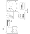
- FIG. 1 is a schematic configuration diagram showing an example of a device management system according to this embodiment.
- the device management system SYS shown in this figure includes a device 1 having a refrigerant and a device management device 2 capable of communicating with the device 1 .
- the device 1 is, for example, an air conditioner that includes an outdoor unit 100 and an indoor unit 200 .
- the device management device 2 is a data management destination that stores communication data from the device 1 and estimates the amount of refrigerant in the device 1 .
- the external terminal 3 and the cloud 4 are exemplified as the device management device 2 .
- the external terminal 3 is a terminal device such as a smartphone or a PC (Personal Computer). In addition to communicating with the device 1 , the external terminal 3 may communicate with the cloud 4 and transmit communication data from the device 1 to the cloud 4 .
- the cloud 4 is a group of arithmetic processing units connected via a communication network such as a public line.
- the device management device 2 may be the external terminal 3 or the cloud 4 .
- the device management system SYS communicates with the device 1 based on device acquisition data 10 acquired by the device 1, device information 20 regarding the device 1, and device installation information 30 regarding the installation environment in which the device 1 is installed.
- a connected external terminal 3 or a device management device 2 such as a cloud 4 estimates the amount of refrigerant in the device 1 .
- the device acquisition data 10 includes a measured value of the coolant temperature in the device 1 (hereinafter referred to as “refrigerant temperature 11”) and a measured value of the electrical characteristics in the device 1 (hereinafter referred to as “electrical input 12”). ) and measurement information such as a measured value of environmental information such as temperature or humidity around the device 1 (hereinafter referred to as “environmental information 13”).
- the device 1 transmits device acquisition data 10 to the device management apparatus 2 .
- the device management device 2 acquires the device acquisition data 10 transmitted from the device 1.
- the device management apparatus 2 also has preset device information 20 and device installation information 30 .
- the device information 20 includes inspection data before shipment.
- the device information 20 includes inspection data (stationary data or time-series data) of refrigerant temperature in the device 1 under specific inspection conditions, electrical characteristics in the device 1, or environmental information, inspection conditions, specifications (configuration) of the device 1 at the time of inspection.
- the device installation information 30 includes the environment or installation state of the place where the device is installed. Details of the device acquisition data 10, the device information 20, and the device installation information 30 will be described later.
- FIG. 2 is a diagram showing an example of a refrigerant circuit of equipment according to the present embodiment.
- the outdoor unit 100 and the indoor unit 200 are connected by inside/outside connection pipes 301 and 302 .
- a refrigerant in a gaseous state passes through the internal/external connection pipe 301 .
- a coolant in a liquid state passes through the internal/external connection pipe 302 .
- the four-way valve 101 provided in the outdoor unit 100 to switch the circulation direction of the refrigerant, the heating operation and the cooling operation are switched.
- the direction of the solid line arrow indicates the direction of refrigerant flow during cooling operation, and the direction of the broken line arrow indicates the direction of refrigerant flow during heating operation.
- gaseous refrigerant compressed by the compressor 102 of the outdoor unit 100 flows through the four-way valve 101 and the internal/external connection pipe 301 to the indoor heat exchanger 201 of the indoor unit 200 .
- the refrigerant in the indoor heat exchanger 201 exchanges heat with the ambient air to warm the ambient air.
- the refrigerant that has become liquid due to heat exchange flows through the internal/external connection pipe 302 to the expansion valve 103 of the outdoor unit 100 , and flows through the expansion valve 103 into the outdoor heat exchanger 104 .
- the refrigerant in the outdoor heat exchanger 104 exchanges heat with the surrounding air.
- Refrigerant in a gaseous state through heat exchange passes through the four-way valve 101 and returns to the compressor 102 .
- gaseous refrigerant compressed by the compressor 102 of the outdoor unit 100 flows through the four-way valve 101 into the outdoor heat exchanger 104 .
- the refrigerant in the outdoor heat exchanger 104 exchanges heat with the surrounding air.
- the refrigerant that has become liquid due to heat exchange flows through the expansion valve 103 and the internal/external connecting pipe 302 into the indoor heat exchanger 201 of the indoor unit 200 .
- the refrigerant in the indoor heat exchanger 201 exchanges heat with the surrounding air to cool the surrounding air.
- the refrigerant that has become gaseous due to heat exchange returns to the compressor 102 of the outdoor unit 100 through the internal/external connection pipe 301 and the four-way valve 101 .
- FIG. 3 is an explanatory diagram of the temperature measurement points T1 to T8 shown in FIG.
- a temperature sensor is provided on each of the outlet side and the inlet side of the compressor 102, the outlet side measuring point T1 is the outlet side measuring point, and the inlet side measuring point T8 is the suction temperature measuring point.
- the expansion valve 103 and the outdoor heat exchanger 104 of the outdoor unit 100 and the indoor heat exchanger 201 of the indoor unit 200 are each provided with three points: the outlet side, the inlet side, and the middle point between the outlet and the inlet. is provided with a temperature sensor.
- the outdoor heat exchanger 104 functions as a condenser during cooling operation.
- Measurement points T2, T2-3, and T3 are measurement points for the inlet temperature, intermediate temperature, and outlet temperature of the condenser during cooling operation, respectively.
- the outdoor heat exchanger 104 functions as an evaporator during heating operation.
- Measurement points T2, T2-3, and T3 are measurement points for the outlet temperature, intermediate temperature, and inlet temperature of the evaporator during heating operation, respectively.
- the measurement point T4 serves as a measurement point for the inlet temperature of the expansion valve 103 during cooling operation, and for the outlet temperature of the expansion valve 103 during heating operation.
- the measurement point T5 serves as a measurement point for the outlet temperature of the expansion valve 103 during cooling operation and for the inlet temperature of the expansion valve 103 during heating operation.
- the device 1 may be a multi-type air conditioner (a so-called package air conditioner) in which a plurality of indoor units 200 are connected to one outdoor unit 100.
- a multi-type air conditioner a so-called package air conditioner
- the number of devices 1 is basically one for one outdoor unit 100 regardless of whether there is one indoor unit 200 or a plurality of indoor units 200 .
- the enthalpy decreases due to heat exchange with the air by the condenser. If the amount of refrigerant gas and the amount of heat exchange in the condenser are sufficient, the measurement point T3 transitions into the liquid phase region (see FIG. 6). On the other hand, if the amount of refrigerant gas is insufficient, heat exchange in the condenser and evaporator will be insufficient.
- FIG. 7 is a diagram showing an example of an electric circuit of the device 1 according to this embodiment.
- the same reference numerals are given to the components corresponding to the parts in FIG.
- the outdoor unit control unit 110 controls switching of the refrigerant flow direction in the four-way valve 101, controls the compressor 102, controls the opening degree of the expansion valve 103, and controls the outdoor fan 105 that blows air to the outdoor heat exchanger 104. Rotation control, etc.
- the compressor 102 includes a compression section 102a and a compressor motor 102b.
- Compression part 102a has a compression mechanism such as a rotary type or a scroll type, compresses the refrigerant sucked from the inlet side, and discharges it from the outlet side.
- Compressor motor 102b includes a three-phase motor whose rotation can be controlled by inverter 120, and drives the compression mechanism of compression section 102a. By controlling the inverter 120, the outdoor unit control section 110 controls the rotation of the compressor motor 102b to control the compression mechanism of the compression section 102a.
- the indoor unit 200 includes an indoor unit control section 210.
- the indoor unit control unit 210 includes a microcomputer, controls each unit of the indoor unit 200, and acquires measurement values of various sensors provided in the indoor unit 200. For example, the indoor unit control unit 210 acquires the measured values of the temperature sensors provided at the refrigerant temperature measurement points T6, T6-7, and T7 described with reference to FIGS. 2 and 3, respectively.
- the indoor unit control unit 210 also controls the rotation of the indoor fan 202 that blows air to the indoor heat exchanger 201, and the like.
- the air conditioning load of the outdoor and indoor units is constant like in a test room.
- the air conditioning load applied to the outdoor unit changes due to the outside temperature not being constant throughout the day.
- the air conditioning load applied to the indoor unit changes depending on the number of people in the room or their activity status.
- the device management device 2 (external The terminal 3 or the cloud 4) estimates the amount of refrigerant in the device 1.
- the equipment management system SYS can accurately estimate the amount of refrigerant in the equipment 1 in the actual use environment without requiring any special operation. A detailed description will be given below.
- Temperature sensors may also be provided in the internal/external connection pipes 301 and 302, and the temperature of the internal/external connection pipe 301 (for example, inlet temperature and outlet temperature) may be included in the coolant temperature 11.
- the coolant temperature 11 is not limited to the temperature at the location described above, and may include the coolant temperature at any location that can be acquired by the device 1 .
- the refrigerant temperature 11 includes measured values of the refrigerant temperature at more points, the higher the refrigerant amount estimation accuracy.
- the environmental information 13 includes, for example, ambient temperature (outdoor temperature, indoor temperature) and humidity (outdoor humidity, indoor humidity) acquired by the outdoor unit 100 and the indoor unit 200 .
- the environment information 13 may include all of the above data items, or may include some of them.
- the environment information 13 preferably includes at least room temperature.
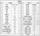
- the common items include the specifications (configuration) of the device 1 at the time of inspection.
- common items include date and time of inspection (No. 1), test room used for inspection (No. 2), manufacturing information and product specifications of the inspected device 1, and the like.
- the manufacturing information includes lot number (No. 3), manufacturing year (No. 6), and the like.
- the model No. 4
- capacity No.
- the receiver is provided, for example, in the vicinity of the connecting portion between the expansion valve 103 of the outdoor unit 100 and the internal/external connection pipe 302 .
- This receiver is provided to store surplus refrigerant because the required amount of refrigerant differs between cooling operation and heating operation.
- the internal volume of the outdoor unit 100 is larger than that of the indoor unit 200, and the amount of refrigerant in the indoor unit 200 serving as a condenser during heating operation is smaller than that of the outdoor unit 100 during cooling operation.
- No. of inspection data items 1 to No. Item 5 is a common inspection condition regardless of the type of equipment 1 .
- the common inspection conditions include test conditions (for example, cooling standard or heating standard), outdoor DB (Dry Bulb), outdoor WB (Wet Bulb), indoor DB, and indoor WB.
- the device information 20 may include all of the above data items, or may include some of them.
- the device information 20 preferably includes at least the refrigerant type and the volume of space through which the refrigerant can flow.
- the volume of the space through which the refrigerant can flow is the internal volume of the compressor 102, the internal volume of the outdoor heat exchanger 104, the internal volume of the indoor heat exchanger 201, the internal volume of the receiver, and the like.
- the volume of the space through which the refrigerant can flow may include part of the internal volume of the compressor 102, the internal volume of the outdoor heat exchanger 104, the internal volume of the indoor heat exchanger 201, and the internal volume of the receiver. and all may be included.
- the device information 20 may include any measurable information at the time of inspection. The more data items included in the device information 20, the higher the refrigerant amount estimation accuracy.
- the device installation information 30 includes the position (latitude, longitude) of the installation location of the device 1, the building specifications, the installation direction (facing north, facing south, etc.), the installation method of the outdoor unit 100 (on the roof, on the ground, on the ceiling, etc.). hanging, wall surface, etc.), the height of the indoor unit 200 (height from the floor surface), the size of the indoor space, the length and diameter of the internal and external connection pipes 301 and 302 that connect the outdoor unit 100 and the indoor unit 200,
- the height difference (indoor/outdoor height difference) between the outdoor unit 100 and the indoor unit 200 is included as information such as the installation location or the installation environment.
- the indoor/outdoor height difference is the height difference between the position where the inside/outside connection pipes 301 and 302 are connected to the outdoor unit 100 and the position where the inside/outside connection pipes 301 and 302 are connected to the indoor unit 200 .
- the device installation information 30 may include all of the above data items, or may include some of them.
- the equipment installation information 30 preferably includes the length and diameter of the internal/external connection pipes 301 and 302, which are related to the volume of the space through which the refrigerant can flow.
- the device installation information 30 may include any information other than the above data items regarding the environment or installation state of the installation location. The more data items included in the equipment installation information 30, the higher the refrigerant amount estimation accuracy.
- the installation location or installation environment of the device 1 differs depending on the user. If the installation location or installation environment is different, the estimation of the refrigerant amount is also affected. For example, regarding the installation location of the device 1, when the outdoor unit 100 is installed on the first floor, when the indoor unit 200 is installed on the first floor and when the indoor unit 200 is installed on the third floor, the outdoor unit The height of the indoor unit 200 with respect to 100 is generally different by about 5m. Therefore, even if the amount of refrigerant in the device 1 excluding the internal/external connection pipes 301 and 302 is the same, the lengths of the internal/external connection pipes 301 and 302 are different, so it is assumed that different behaviors will be exhibited in terms of the refrigeration cycle. . Therefore, it is conceivable that the installation location of the device 1 affects the estimation of the amount of refrigerant.
- the lengths of the internal/external connection pipes 301 and 302 may differ. In that case, since the refrigerant is distributed in the internal/external connection pipes 301 and 302, if the additional refrigerant is not charged for the length of the internal/external connection pipes 301 and 302, the amount of refrigerant in the device 1 excluding the internal/external connection pipes will be reduced. It is conceivable that it will decrease in general and cause a gas shortage. Regarding the installation environment of the device 1, the lengths of the internal/external connection pipes 301 and 302 differ depending on whether the outdoor unit 100 is suspended from the ceiling, placed on the ground, or placed on the roof.
- the air conditioning load differs depending on whether it is facing south and exposed to direct sunlight or facing north and is in the shade, which affects the refrigeration cycle. Therefore, it is conceivable that the installation environment of the device 1 similarly affects the estimation of the amount of refrigerant.
- the insulation performance differs depending on whether the building in which the device 1 is installed is made of wood or reinforced concrete. For example, if the building is made of wood and has low heat insulation, the air conditioning load will increase, which may affect the refrigeration cycle and affect the estimation of the amount of refrigerant.
- the device management apparatus 2 uses the device installation information 30 to estimate the amount of refrigerant according to the installation location or installation environment of the device 1 without fixing the installation location or installation environment of the device 1. be able to.
- FIG. 12 is a schematic block diagram showing an example of the configuration of the device management apparatus 2 according to this embodiment.
- the device management device 2 is the external terminal 3 or the cloud 4 as described above, and includes, for example, a storage unit 401 , a communication unit 402 and a processing unit 403 .
- the storage unit 401 stores control programs for controlling each unit of the device management apparatus 2 and various data.
- the storage unit 401 includes DRAM (Dynamic Random Access Memory), EEPROM (Electrically Erasable Programmable Read Only Memory), Flash ROM, HDD (Hard Disk Drive), SSD (Solid State Drive) ), etc.
- the device information 20 (see FIG. 10) and the device installation information 30 (see FIG. 11) are pre-stored in the storage unit 401 .
- the communication unit 402 performs data communication with the device 1 or other devices by wireless communication.
- the communication unit 402 connects to a communication network such as a wireless LAN (Local Area Network) or the Internet by wireless communication, and performs data communication with the device 1 or other devices. do.
- the communication unit 402 may also support wired communication.
- the processing unit 403 has a CPU (Central Processing Unit) executing a control program stored in the storage unit 401 to perform a refrigerant amount estimation process for estimating the amount of refrigerant. 405 and an output unit 406 .
- the acquisition unit 404 acquires the device acquisition data 10 (see FIG. 8) from the device 1 (for example, the indoor unit 200) via the communication unit 402 and stores it in the storage unit 401.
- FIG. Estimating unit 405 estimates the amount of refrigerant in device 1 .
- the estimated refrigerant amount is referred to as "estimated refrigerant amount 40".
- the estimation unit 405 calculates the estimated refrigerant amount 40 in the device 1 based on the device acquisition data 10 acquired by the acquisition unit 404 and the device information 20 and the device installation information 30 stored in the storage unit 401. calculate.
- the output unit 406 outputs the estimation result of the refrigerant amount by the estimation unit 405 .
- FIG. 13 is a flowchart showing an example of refrigerant amount estimation processing according to the present embodiment.
- the device 1 (for example, the indoor unit 200) sends the device acquired data 10 to the device management device 2, either voluntarily or passively by the user who operates the device 1, periodically (for example, every five minutes). Send.
- the device management apparatus 2 receives the device acquisition data 10 transmitted from the device 1 (step S101).
- the device management apparatus 2 Upon receiving the device acquisition data 10 transmitted from the device 1, the device management apparatus 2 acquires the device acquisition data 10 each time it is received, and stores and accumulates it in the storage unit 401 (step S103).
- the device management device 2 estimates the amount of refrigerant in the device 1 at any timing, in addition to internal periodic processing.
- the device management apparatus 2 determines whether or not it is time to estimate the amount of refrigerant (step S105). If it is not the refrigerant amount estimation timing (NO), the process returns to step S101, and the device management apparatus 2 periodically receives the device acquisition data 10 from the device 1 (step S103).
- the device management device 2 estimates the amount of refrigerant in the device 1 (step S107). Specifically, the equipment management apparatus 2 calculates the estimated refrigerant amount 40 based on the accumulated equipment acquisition data 10 and the equipment information 20 and the equipment installation information 30 held internally in advance. Then, the device management device 2 outputs the estimated refrigerant amount (estimated refrigerant amount 40) (step S109).
- FIG. 14 is an explanatory diagram showing an example of a method for calculating an estimated amount of refrigerant according to this embodiment.
- the equipment management apparatus 2 calculates an estimated refrigerant amount 40 by summing a converted refrigerant amount 41, a dissolved refrigerant amount 42, and a retained refrigerant amount 43, for example.
- the estimated refrigerant amount 40 may be set directly if it can be determined from the refrigerant charging operation or the like.
- the equivalent refrigerant amount 41 is the amount of refrigerant in the main refrigerant state in each part that constitutes the device 1 .
- the converted refrigerant amount 41 indicates the amount of refrigerant in the gas phase portion.
- the converted refrigerant amount 41 indicates the amount of refrigerant in the gas phase portion.
- the converted refrigerant amount 41 indicates the refrigerant amount using the two-phase average density.
- the equivalent refrigerant amount 41 is calculated by multiplying the internal volume of each part of the device 1 by the refrigerant density.
- a converted refrigerant amount 41 is included in the internal volume 31 of the internal/external connection pipes 301 and 302 determined from the equipment installation information 30 (the length and diameter of the internal/external connection pipes 301 and 302) and the equipment information 20. It is calculated by multiplying the internal volume 51 of each part in the equipment 1 and the refrigerant density 50 in each part.
- the refrigerant density in each component can be obtained from the relationship between pressure and density by converting the refrigerant temperature of the equipment acquisition data 10 into pressure.
- the relationship between pressure and density is determined by the type of refrigerant.
- the data of the refrigerant pressure can be directly acquired from the device 1, it can be obtained based on the acquired refrigerant pressure or pressure data.
- Each component described here is a component having a space in which a refrigerant can flow among the components constituting the device 1, and includes, for example, the compressor 102, the outdoor heat exchanger 104, the indoor heat exchanger 201, the receiver, the internal and external They are connecting pipes 301 and 302 and the like.
- the dissolved refrigerant amount 42 is the amount of refrigerant dissolved in the refrigerating machine oil used in the equipment 1 .
- the dissolved refrigerant amount 42 is calculated by summing up the product of the retained oil amount 52 of each part and the oil dissolution ratio 53 of each part for each part.
- the total amount of oil in the equipment 1 is the value of the oil amount in the equipment information 20 shown in FIG.
- a retained oil amount 52 remaining in each component out of the amount of oil in the equipment 1 is determined based on the equipment acquisition data 10, the equipment information 20, and the equipment installation information 30 according to the operating conditions (cooling, heating, etc.). obtained by experiments or numerical calculations.
- the device information 20 further includes a retained oil amount 52 for each component determined by this experiment or numerical calculation.
- the oil dissolution ratio 53 of each component can be calculated using a Daniel chart showing the amount of refrigerant dissolved in refrigerating machine oil according to temperature and pressure by an experimental method.
- the current oil dissolution ratio 53 of each part can be calculated using the measured value of the refrigerant temperature of each part included in the device acquisition data 10 and the Daniel chart. When obtaining using a Daniel chart, it may be calculated by an approximation formula.
- the retained oil amount 52 of each part may target only the parts that have a large internal volume and in which the refrigerating machine oil tends to stagnate, and may exclude the parts in which the refrigerating machine oil is less likely to stagnate.
- refrigerating machine oil tends to stay in the compressor 102, the outdoor heat exchanger 104, and the indoor heat exchanger 201 and is present in large amounts.
- the retained refrigerant amount 43 is the amount of liquid refrigerant retained in each component (receiver, internal/external connection pipes 301, 302, etc.) in the gas-liquid two-phase region. If the cross-sectional area of the coolant channel of each component is small, the flow velocity of the coolant becomes faster, making it difficult for the coolant to stagnate. Therefore, for example, as shown in FIG. 14, the amount of retained refrigerant 43 circulates through the cross-sectional area of the refrigerant flow path of each component and inside the device 1 based on the device acquisition data 10, the device information 20, and the device installation information 30. It can be obtained by experiments or numerical calculations depending on the refrigerant flow rate.
- the flow rate of refrigerant circulating in the device 1 is determined by the frequency of the compressor 102 and the density of the suctioned refrigerant.
- the suctioned refrigerant density can be uniquely obtained from the amount of heat exchange between the condenser and the evaporator in the equipment 1 . Note that it can also be obtained from the intake temperature or pressure acquired by the device 1 .
- the amount of heat exchanged between the condenser and the evaporator is determined by the outdoor or indoor environmental load, and can be obtained from the device acquisition data 10 and the device installation information 30 at this time.
- the device management device 2 controls the refrigerant temperature in the device 1, the electrical input (electrical characteristics) of the device 1, and the environmental information around the device 1. Acquires device acquisition data 10 (measurement information) indicating the measurement result of . Then, the equipment management apparatus 2 calculates an estimated refrigerant amount 40 based on the obtained equipment acquisition data 10 and preset equipment information 20 and equipment installation information 30 to estimate the amount of refrigerant in the equipment 1 . In addition, for example, the estimation of the refrigerant amount may be performed by the external terminal 3 , the cloud 4 , or the cloud 4 via the external terminal 3 .
- the equipment management system SYS can estimate the amount of refrigerant in the equipment 1 during normal operation, unlike the conventional method of estimating the amount of refrigerant. That is, the equipment management system SYS can accurately estimate the amount of refrigerant in the equipment in the actual use environment without requiring any special operation.
- the device information 20 includes at least information about the volume of the space through which the refrigerant can flow within the device 1 and the type of refrigerant possessed by the device 1 .
- the equipment management system SYS can estimate the amount of refrigerant in the space in which the refrigerant can flow in the equipment 1 according to the refrigerant type.
- the device management device 2 calculates the amount of refrigerant in the device 1 based on the volume of the space through which the refrigerant can flow in the device 1 and the refrigerant density determined based on the refrigerant temperature and refrigerant type in the device 1 .
- the device management system SYS can accurately estimate the amount of refrigerant in the device 1 .
- the equipment management device 2 further calculates the amount of refrigerant dissolved in the refrigerating machine oil used in the equipment 1 (dissolved refrigerant amount 42) and the amount of refrigerant in the liquid stagnant portion (accumulated refrigerant amount 43) in the equipment 1.
- the amount of refrigerant is calculated. That is, the equipment management apparatus 2 calculates the estimated refrigerant amount 40 by summing the converted refrigerant amount 41 , the dissolved refrigerant amount 42 , and the retained refrigerant amount 43 .
- the equipment management system SYS can accurately estimate the amount of refrigerant in the equipment 1 even in a transient phenomenon.
- an outdoor unit 100 including a compressor 102, an outdoor heat exchanger 104, and an expansion valve 103, and an indoor unit 200 including an indoor heat exchanger 201 use internal/external connection pipes 301 and 302 through which refrigerant flows.
- the device installation information 30 includes at least information about the volume of the internal/external connection pipes 301 and 302 (for example, the diameter and length of the internal/external connection pipes 301 and 302).
- the device management system SYS can accurately estimate the amount of refrigerant in the device 1, including the connecting portion between the outdoor unit 100 and the indoor unit 200.
- the environmental information around the device 1 includes at least information about the ambient temperature of the device 1 .
- the ambient temperature is the temperature (indoor temperature) of the environment (indoor) in which the indoor unit 200 is installed or the temperature (outdoor temperature) of the environment (outdoor) in which the outdoor unit 100 is installed.
- the device management system SYS can accurately estimate the amount of refrigerant in the device 1 in consideration of the ambient temperature of the device 1 .
- the device management system SYS is equipped with an external terminal 3 or a cloud 4 capable of communicating with the device 1 as the device management device 2 . Accordingly, the device management system SYS can be easily applied to various devices 1 because the device 1 does not need to have a function necessary for estimating the amount of refrigerant.
- the refrigerant amount estimation method for estimating the refrigerant amount in the device 1 having the refrigerant is such that the device management device 2 determines the refrigerant temperature in the device 1, the electrical input of the device 1 ( electrical characteristics), and device acquired data 10 (measurement information) indicating the measurement result of environmental information around the device 1; acquired device acquired data 10; and estimating the amount of refrigerant in the device 1 based on the installation information 30 .
- the equipment management system SYS can estimate the amount of refrigerant in the equipment 1 during normal operation, unlike the conventional method of estimating the amount of refrigerant. That is, the equipment management system SYS can accurately estimate the amount of refrigerant in the equipment in the actual use environment without requiring any special operation.
- FIG. 15 is a schematic configuration diagram showing an example of a device management system according to this embodiment.
- the device management system SYS shown in this figure includes a plurality of devices 1 having refrigerant and a device management device 2 capable of communicating with each device 1 .
- this figure shows an example in which there are three devices 1, the number may be two or four or more.
- the configuration and operation of the refrigerant amount estimation process in the equipment management system SYS are the same as in the first embodiment.
- the acquisition unit 404 acquires the device acquisition data 10 from each of the multiple devices 1 .
- the estimation unit 405 calculates the amount of refrigerant (total amount of refrigerant) in the plurality of devices 1 based on the device acquisition data 10 acquired by the acquisition unit 404 and the preset device information 20 and device installation information 30 .
- the device management system SYS collectively manages the device acquisition data 10, the device information 20, and the device installation information 30 of each of the plurality of devices 1, thereby controlling the total refrigerant amount (refrigerant amount) of the plurality of devices 1. total amount) can be estimated.
- the equipment management system SYS can also individually estimate the amount of refrigerant for each of the plurality of equipment 1 .
- the basic configuration of the equipment management system SYS according to this embodiment is the same as in the first and second embodiments. Also, the basic operation of the equipment management system SYS according to this embodiment is the same as in the first and second embodiments, but differs in that the refrigerant management value is used.
- refrigerants with a high global warming potential tend to gradually reduce their use in the market.
- GWP of R410a is 2090 and GWP of R32 is 675.
- R410a is a refrigerant that has three times as much global warming effect as R32. Therefore, when R410a is used, the impact on the global environment (global warming) is equalized by limiting the amount of refrigerant to one third of the amount of refrigerant when using R32.
- the amount of refrigerant whose use is restricted in the device 1 for each type of refrigerant is the above-mentioned refrigerant management value.
- the refrigerant management value is calculated as the sum of the charged refrigerant amount at the time of shipment of the device 1 and the additional charged refrigerant amount required for the device 1 .
- FIG. 16 is a schematic configuration diagram showing an example of a device management system according to this embodiment.
- the equipment management device 2 estimates the amount of refrigerant in the equipment 1 based on the equipment acquisition data 10, the equipment information 20, and the equipment installation information 30, and calculates the estimated refrigerant amount (estimated refrigerant amount 40) and the refrigerant management value. can be compared to determine whether the amount of refrigerant in the device 1 is excessive or insufficient.
- the configuration is such that the amount of refrigerant in the device 1 is estimated at an arbitrary timing, so time-series data as shown in FIG. 17 can be retained.
- the estimating unit 405 calculates the refrigerant management value of the device 1 based on the sum of the charging refrigerant amount at the time of shipment of the device 1 and the additional charging refrigerant amount required for the device 1 . Then, the estimating unit 405 compares the estimated refrigerant amount value in the device 1 with the refrigerant management value of the device 1, and determines whether the amount of refrigerant in the device is excessive or insufficient.
- FIG. 17 is a diagram showing an example of time-series data held by the device management apparatus. This figure shows time-series data of the refrigerant management value and the estimated refrigerant amount value at each time.
- the estimated refrigerant amount value from time t0 to t1 is an estimated value of the refrigerant amount filled in the device 1 at the time of installation, and corresponds to the charged refrigerant amount of the device 1 at the time of shipment.
- the estimated refrigerant amount value is close to the refrigerant management value at time t2.
- the estimated refrigerant amount after time t3 decreases, and then after time t4, the estimated refrigerant amount reaches a certain value. value stabilizes.
- the device management device 2 can determine whether the amount of refrigerant in the device 1 is excessive or insufficient by comparing the difference between the refrigerant management value and the estimated refrigerant amount value based on the time-series data shown in FIG.
- the equipment management device 2 can grasp that the refrigerant gas is leaking.
- the device management device 2 determines whether the amount of refrigerant in the device 1 is excessive or deficient at an arbitrary timing with high determination accuracy (for example, after 30 minutes have passed since the start of the device 1), or periodically (for example, (every one minute), and output as instantaneous values or time-series data.
- the equipment management device 2 simply determines whether the amount of refrigerant in the equipment 1 is excessive or insufficient when judging whether the amount of refrigerant is excessive or insufficient for one equipment 1 .
- the device management device 2 can also manage the amount of refrigerant used in the market when judging whether the amount of refrigerant is excessive or insufficient for a plurality of devices 1 .
- FIG. 18 is a diagram showing an example of time-series data of each of a plurality of devices 1 (here, device A, device B, and device C) held by the device management apparatus 2. As shown in FIG.
- the device management apparatus 2 obtains the sum of the estimated refrigerant amount values at time t0 when each of the plurality of devices 1 is installed, so that the device management apparatus 2 can grasp the total refrigerant amount of the plurality of devices 1 at the time of installation. can.
- only device A is additionally charged with refrigerant between time t1 and time t2, and the refrigerant gas in device A decreases between time t3 and time t4, so refrigerant leakage occurs.
- device C has refrigerant leakage between time t2 and time t3.
- the devices A to C were removed at time t4, it can be seen that the rest of the refrigerant, excluding the refrigerant leaked from the devices A and C, could be recovered.
- the recovered refrigerant does not affect the environment even if it is replaced with a new device 1 having the same amount of refrigerant.
- the device 1 having the refrigerant can be used continuously.
- the new device 1 uses a different type of refrigerant, it can be replaced without affecting the environment by applying a refrigerant control value according to the type of refrigerant.
- the basic configuration of the equipment management system SYS according to this embodiment is the same as in the first and second embodiments. Further, the basic operation of the device management system SYS according to this embodiment is the same as in the first and second embodiments, but the performance of the device 1 is estimated based on the estimated refrigerant amount 40 and the estimated The difference is that the obtained operating performance is compared with the device information 20 of the device 1, published inspection data, catalog information, or the like.
- the catalog information is information described in the catalog of the manufacturer of the device 1 and includes, for example, numerical values regarding the specifications of the device 1 .
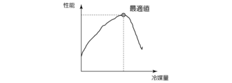
- FIG. 19 is a diagram showing an example of the relationship between the amount of refrigerant and the performance of equipment according to this embodiment.
- FIG. 20 is a diagram showing an example of comparison with catalog values for the relationship between the performance of the device and the air temperature according to this embodiment.
- the performance of the equipment 1 indicates, for example, operation performance such as cooling, heating, dehumidification, and freezing. Note that the power consumption of the device 1 may be used as the performance of the device 1 .
- the equipment management device 2 calculates the estimated refrigerant amount 40 of the equipment 1 having the characteristics as shown in FIG. Then, the device management apparatus 2 summarizes the calculated performance of the device 1 as characteristics as shown in FIG. 19 is determined by numerical calculation based on the device information 20 and the device installation information 30. FIG. Similarly, the example shown in FIG. 20 is also determined by numerical calculation based on the device information 20, published inspection data, or catalog information. The inspection data or catalog information to be published is included in the equipment information 20 .
- the device management system SYS estimates the performance of the device 1 based on the device information 20, the device installation information 30, and the estimated amount of refrigerant, thereby grasping the performance of the device 1. can do. Further, when the device management system SYS has a plurality of devices 1, the device management system SYS can grasp the performance of each device 1 as well as the performance of the plurality of devices 1 as a whole. Furthermore, the device management system SYS compares the estimated performance of each device 1 or the overall performance of a plurality of devices 1 with the device information 20, published inspection data, or catalog information, thereby Performance can be evaluated, and, for example, the adequacy of the performance of the device 1 can be grasped.
- the basic configuration of the equipment management system SYS according to this embodiment is similar to that of the first and second embodiments, but differs in that a general-purpose device is further provided.
- FIG. 21 is a schematic configuration diagram showing an example of a device management system according to this embodiment.
- the equipment management apparatus 2 is configured to be able to communicate with the general-purpose device 5 .
- the general-purpose device 5 is an example of an external device, such as a device having a display screen (eg, smart phone, PC) or a device that emits sound (eg, wireless earphones).
- the basic operation of the equipment management system SYS is the same as in the first to fourth embodiments, but the estimated refrigerant amount 40 of the equipment 1 calculated by the equipment management device 2 or information based on the performance is sent from the general-purpose device 5 The difference is that the output provides visual or auditory guidance or warning to the user.
- the device management device 2 transmits the estimated refrigerant amount 40 or performance information of the device 1 to the general-purpose device 5 to display it.
- the equipment management apparatus 2 transmits information about excess or deficiency of the amount of refrigerant in the equipment 1 determined based on the result of comparison between the value of the estimated refrigerant amount 40 of the equipment 1 and the refrigerant management value to the general-purpose device 5. It may be displayed on the general-purpose device 5 by doing so.
- the equipment management apparatus 2 transmits to the general-purpose device 5 the information of the judgment result based on the comparison between the performance of the equipment 1 and the equipment information 20, inspection data to be published, or catalog information. may be displayed.
- the output unit 406 of the device management device 2 outputs the estimated refrigerant amount 40 or performance information of the device 1 to the communication unit 402 to transmit it to the general-purpose device 5 .
- the general-purpose device 5 acquires the estimated refrigerant amount 40 or performance information of the equipment 1 transmitted from the equipment management apparatus 2 and displays it on the display screen of the general-purpose device 5 .
- the output unit 406 outputs information about the amount of refrigerant in the device 1 to the general-purpose device 5 by outputting the information to the communication unit 402 .
- the general-purpose device 5 acquires the information about the excess or deficiency of the amount of refrigerant in the equipment 1 transmitted from the equipment management apparatus 2 and displays it on the display screen of the general-purpose device 5 .
- the general-purpose device 5 may output the information transmitted from these device management apparatuses 2 by voice.
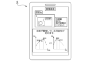
- FIG. 22 is a diagram showing a display example displayed on the general-purpose device 5 according to this embodiment.
- This figure shows a display example of information that guides or warns the value of the estimated refrigerant amount 40, the shortage of the amount of refrigerant in the device 1, the fact that the refrigerant is leaking, the performance determination result, and the like.
- the display example shown in this figure is only an example, and the present invention is not limited to this.
- the visual or auditory guidance or warning is provided, for example, when it is determined that the amount of refrigerant in the device 1 is continuously insufficient. In this case, the refrigerant gas is considered to be leaking. Therefore, the user is urged to contact the administrator or repairer of the device 1, or the device 1 is operated so as to minimize the effect of the refrigerant gas leakage. If it is in the middle, it is intended to prompt the user to perform an operation to stop or to switch to a mode for shutting off refrigerant leakage.
- the performance of the device 1 can be represented by a function with the amount of refrigerant as a parameter.
- the power consumption as an example of the performance of the device 1, if the amount of refrigerant is insufficient, the amount of heat exchanged in the heat exchanger will decrease according to the decrease, so the power consumption will decrease. .
- a similar trend is observed for cooling, heating, dehumidifying, or freezing performance.
- the device management device 2 can obtain the performance of the device 1 based on the estimated amount of refrigerant, and visually display the result to the user or administrator who uses the device 1 via the general-purpose device 5. Alternatively, an audible guidance or warning is provided. Further, even when a plurality of devices 1 are connected, the device management apparatus 2 can obtain the performance of each device 1 based on the refrigerant amount estimated for each device 1 . In addition, the device management apparatus 2 compares the obtained performance of each device 1 with the device information 20, published inspection data, or catalog information so that the performance of each device 1 can be objectively judged.
- the device management device 2 determines that the performance is reduced due to the insufficient amount of refrigerant gas. Visually or audibly guides or warns of the deterioration.
- FIG. 23 is a diagram showing a display example displayed on the general-purpose device 5 according to this embodiment.
- the information of the device the start date of operation, the device name, and the model of the compressor are displayed.
- the installation information of the device information about the installation location of the outdoor unit and the height at which the indoor unit is installed is displayed.
- Graphs of time-series data of the estimated refrigerant amount value and performance of the device 1 and the estimated refrigerant amount value and refrigerant management value are also displayed. These pieces of display information are information that assists work in failure or maintenance.
- the display example shown in this figure is only an example, and the present invention is not limited to this.
- the equipment management system SYS outputs information regarding failure or maintenance of the equipment 1 via the general-purpose device 5 based on the estimation result of the refrigerant amount or performance of the equipment 1 .
- the equipment management system SYS can confirm information that assists work in the failure or maintenance of the equipment 1 . Therefore, according to the present embodiment, it is possible to reduce the burden on the operator when the equipment 1 fails or perform maintenance, and to improve the efficiency of the work.
- the device management system SYS is not limited to cooling or heating, and similarly in the case of dehumidification or freezing, if the environment in which the device 1 is used exceeds the capacity of the device 1, may be dehumidified or refrigerated.
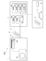
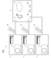
- FIG. 24 is a schematic configuration diagram showing an example of a device management system according to this embodiment.
- the equipment management system SYS consists of equipment 1 of a plurality of owners (owner A, owner B, owner C, . . . ) and equipment management apparatus 2 capable of communicating with each equipment 1.
- An owner is a person, an organization, or the like who owns the device 1 .
- This figure shows a plurality of devices 1 divided by owner in the configuration example of the device management system according to the second embodiment shown in FIG. It is the same in that it is communicably connected to the management device 2 .
- each owner has three devices 1
- the number may be one, two, or four or more.
- the number of owners is also not limited and may include owners in other countries as well as domestic owners.
- the general-purpose device 5 is an example of an external device, such as a device having a display screen (for example, a smartphone, a PC) or a device that emits sound (for example, a wireless earphone). is.
- the general-purpose device 5 is an external device used by each of owner A, owner B, owner C, etc., and is capable of communicating with the device management apparatus 2 .
- the reduction target for the total GWP of greenhouse gas (refrigerant) R410a is set by the Kyoto Protocol.
- the GWP total amount value is a value determined by "GWP (global warming potential) determined by refrigerant type" ⁇ "amount (weight) of refrigerant used".
- the amount (weight) of refrigerant used is, in other words, the amount (weight) of refrigerant charged in the device.
- F-gas (freon gas) regulations in Europe stipulate that the total amount of GWP will be reduced to 20% by 2030. Therefore, in equipment such as air conditioners that use a refrigerant, there is an increasing trend in various countries to reduce the amount of natural refrigerant with a low GWP and the amount of refrigerant used in the equipment.
- the reduction target for the total GWP value since the reduction target for the total GWP value is set, it is necessary to reduce the amount of refrigerant that can be filled in equipment year by year, or switch to a refrigerant with a lower GWP if the same refrigerant is used.
- the equipment sold in the past has remained in the market for 10 to 20 years, and it is essential to recover the refrigerant enclosed in the sold equipment as a social significance. In fact, the refrigerant recovery ratio is 38%, and most of it is released into the atmosphere, giving an adverse effect on global warming.
- the distribution volume of the refrigerant itself is a quota system (Quiota Allocation: distribution permission frame) in order to achieve the reduction target of the total GWP value. If the Quiota Allocation runs out, it cannot be sold. This results in a steep rise in the price of the refrigerant, which affects costs. Therefore, it is necessary to utilize a method of regenerating the refrigerant by reusing the refrigerant recovered from the equipment.
- the device management device 2 acquires the device acquisition data 10 from each of the plurality of devices 1, estimates the refrigerant amount in each of the plurality of devices 1, and Aggregate and manage data.
- FIG. 25 is a schematic block diagram showing an example of the configuration of the device management device 2 according to this embodiment.
- the device management apparatus 2 is the external terminal 3 or the cloud 4, as described above, and includes, for example, a storage unit 401, a communication unit 402, and a processing unit 403, similar to the example shown in FIG.
- the processing unit 403 includes an acquiring unit 404, an estimating unit 405, and an output unit 406 as a functional configuration for estimating the refrigerant amount and managing data by the CPU executing a control program stored in the storage unit 401. , and a data management unit 407 .
- the acquisition unit 404 acquires the device acquisition data 10 (see FIG. 8) from the plurality of devices 1 via the communication unit 402 and stores it in the storage unit 401 .
- the estimation unit 405 estimates each of the refrigerant amounts in the plurality of devices 1 . For example, the estimation unit 405 estimates the amount of refrigerant in the plurality of devices 1 based on the device acquisition data 10 acquired by the acquisition unit 404 and the device information 20 and device installation information 30 stored in the storage unit 401. 40 are calculated respectively.
- the output unit 406 visually or audibly outputs information based on data managed by the data management unit 407 , which will be described later, via the general-purpose device 5 .
- the data management unit 407 associates each of the refrigerant amounts in the plurality of devices 1 estimated by the estimation unit 405 with the refrigerant type and stores them in the storage unit 401 .
- the refrigerant type is the refrigerant type of the refrigerant used in each device 1 .
- the data management unit 407 refers to the device information 20 and identifies the refrigerant type of the refrigerant used in each device 1 .
- the data management unit 407 causes the storage unit 401 to store device refrigerant information such as information on the amount of refrigerant in a plurality of devices 1 estimated by the estimation unit 405 in association with the refrigerant type for each device 1 .
- the data management unit 407 determines the amount of refrigerant for each device 1 based on the amount of refrigerant for each device 1 and the regulation value for the upper limit of the amount of refrigerant that can be used in the space where each of the plurality of devices 1 is installed. It is determined whether or not it is within the regulation value, and determination information based on the determination result is stored in the storage unit 401 .
- the data management unit 407 determines whether or not the refrigerant for each device 1 is to be collected based on the refrigerant type for each device 1, and stores determination information based on the determination result in the storage unit 401. For example, if the type of refrigerant used in the device 1 is prohibited by regulations, the data management unit 407 determines that the refrigerant is to be collected.
- the data management unit 407 stores device refrigerant information associated with the refrigerant type for each device 1, the regulation value, determination information as to whether or not the amount of refrigerant for each device 1 is within the regulation value, and the collected refrigerant for each device 1. Determination information as to whether or not the device is a target is stored as device refrigerant data 410 in the storage unit 401 and managed.
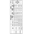
- FIG. 26 is a diagram showing a data example of the device refrigerant data 410 according to this embodiment. Here, an example of data in the case where one device 1 is installed in one space (for example, room) is shown.
- the device refrigerant data 410 stores device refrigerant information, regulation values, determination information, etc. in association with each owner's device 1 .
- the device refrigerant information includes the refrigerant type, the GWP of the refrigerant type, and the refrigerant amount in the device.
- the intra-equipment refrigerant amount is the refrigerant amount (charged refrigerant amount) used for each apparatus 1 and is the value of the estimated refrigerant amount 40 estimated by the estimation unit 405 .
- the GWP total amount value is a value calculated by “GWP ⁇ equipment refrigerant amount”.
- the data management unit 407 may compare the internal refrigerant amount with the refrigerant amount regulation value for each device 1 and determine whether the internal refrigerant amount is within the refrigerant amount regulation value. For example, the data management unit 407 determines whether or not the refrigerant amount in the device is within the refrigerant amount regulation value, and if the device refrigerant amount exceeds the refrigerant amount regulation value, the regulation value is set. Determination information (“regulation”) indicating that the limit is exceeded may be stored in the device refrigerant data 410 .
- regulation Determination information
- the device refrigerant data 410 shown in this figure shows an example in which three devices 1 (two model ZW and one model EW) are installed in the room A.
- the total GWP regulation value is set for one space (here, room A). Therefore, the data management unit 407 calculates the “total GWP value for each space” by summing the “total GWP value for each device” of each of the three devices 1 installed in this room A, and calculates the “total GWP value for each space”. It is determined whether or not the GWP total amount value is within the GWP total amount regulation value.
- the total amount of refrigerant in each device 1 is obtained by dividing the total GWP value of room A by the GWP of the refrigerant type. It may be determined whether or not it is within the value (that is, the refrigerant amount regulation value for room A).
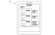
- FIG. 28 is a diagram showing a first example of display of information regarding the amount of refrigerant according to this embodiment.
- This figure shows an example in which information about the amount of refrigerant in the device 1 installed in the room A is displayed on the display screen of the general-purpose device 5 of the owner A.
- FIG. In this example, the type of refrigerant used in each of the three devices 1 installed in room A and the amount of refrigerant in the device (estimated amount of refrigerant 40) are displayed.
- the total refrigerant type and refrigerant amount used in the equipment 1 in room A, the regulation value for the size of room A (the legal regulation value for this refrigerant type), and the refrigerant amount used in room A (total amount of refrigerant) is within the regulation value.
- the total amount of refrigerant (total amount of refrigerant) is within the regulation value, for example, "The total amount of refrigerant is within the standard" is displayed as information indicating that it is within the regulation value.
- FIG. 29 is a diagram showing a second example of display of information regarding the amount of refrigerant according to the present embodiment. Similar to FIG. 28, this figure shows an example in which the display screen of owner A's general-purpose device 5 displays information about the amount of refrigerant in equipment 1 installed in room A. (total amount of refrigerant) exceeds the regulation value. When the total amount of refrigerant (total amount of refrigerant) exceeds the regulation value, information indicating that the regulation value is exceeded is displayed, for example, "Total amount of refrigerant exceeds.”
- FIG. 30 is a diagram showing a third example of display of information regarding the amount of refrigerant according to this embodiment. Similar to FIGS. 28 and 29, this figure shows an example in which information about the amount of refrigerant in the device 1 installed in the room A is displayed on the display screen of the general-purpose device 5 of the owner A. , shows a display example when there is a refrigerant to be collected.
- two of the three devices 1 installed in the room A use refrigerant R32, but one device uses refrigerant R22 whose use is prohibited. Therefore, as information indicating that there is a refrigerant to be collected, for example, "There is a refrigerant to be collected" is displayed.
- FIGS. 28 to 30 show display examples in which three devices 1 are installed in one space (for example, room A). is installed, information about the amount of refrigerant for one vehicle is displayed.
- the information regarding the refrigerant amount of the plurality of devices 1 is displayed in a list, and whether or not the refrigerant amount is within the regulation value is displayed.
- a determination result or a determination result as to whether or not there is a refrigerant to be collected may be displayed for each device 1 .
- the device management system SYS can easily grasp the amount of refrigerant in the plurality of devices 1 installed in the market. Further, the device management system SYS can easily grasp the refrigerant type of the refrigerant used in the plurality of devices 1 installed in the market.
- the device management system SYS can easily grasp whether or not the amount of refrigerant in each of the plurality of devices 1 installed in the market exceeds the regulation value.
- the device management device 2 calculates the total amount of refrigerant for each of the plurality of devices 1 installed in one space and one Based on the regulation value for the upper limit of the amount of refrigerant that can be used in the space, it is determined whether or not the total amount of refrigerant in one space is within the regulation value, and determination information based on the determination result is stored in the storage unit 401.
- the device management apparatus 2 determines whether or not the refrigerant for each device 1 is to be collected based on the refrigerant type for each device 1, and causes the storage unit 401 to store determination information based on the determination result.
- the device management system SYS can easily grasp whether or not the refrigerant type used in each of the plurality of devices 1 installed in the market is subject to recovery.
- the device management system SYS can easily notify users (owners, etc.) of refrigerant types and refrigerant amounts in a plurality of devices 1 installed in the market.
- the notified user may be the owner or the user (person in the space where the device 1 is installed).
- the management method in the device management system SYS is such that the device management device 2 obtains from a plurality of devices 1 having a refrigerant, the refrigerant temperature in the device 1, the electrical input (electrical characteristics) of the device 1, and a step of acquiring device acquisition data 10 (measurement information) indicating the measurement result of environmental information around the device 1; and a step of associating each of the estimated refrigerant amounts in the plurality of devices 1 with the refrigerant type and storing them in the storage unit 401 .
- the device management system SYS can easily grasp the amount of refrigerant in the plurality of devices 1 installed in the market. Further, the device management system SYS can easily grasp the refrigerant type of the refrigerant used in the plurality of devices 1 installed in the market.
- FIG. 31 is a schematic configuration diagram showing an example of a device management system according to this embodiment. This figure differs from the configuration shown in FIG. 24 in that the equipment management device 2 can communicate with the service terminal 6 and the refurbishing factory 7 .
- the service terminal 6 is a portable terminal possessed by a serviceman of a collection company that collects refrigerant from the market (for example, the device 1).
- the service terminal 6 may be a general-purpose device such as a smartphone or tablet PC, or may be a dedicated device.
- the service terminal 6 transmits to the device management apparatus 2 information about the refrigerant type and the amount of refrigerant input by the serviceman when the refrigerant is recovered.
- the estimation unit 405 estimates the estimated amount of refrigerant 40 in the plurality of devices 1 based on the device acquisition data 10 acquired by the acquisition unit 404 and the device information 20 and device installation information 30 stored in the storage unit 401. Calculate each.
- the data management unit 407 sums the amounts of refrigerant in the plurality of devices 1 estimated by the estimation unit 405 for each refrigerant type, and calculates the total amount of refrigerant in the device (hereinafter referred to as the “total amount in the device”). Each refrigerant type is associated and stored in the storage unit 401 . Further, the data management unit 407 associates the refrigerant amount of the recovered refrigerant and the refrigerant amount of the regenerated refrigerant acquired by the acquisition unit 404 with each refrigerant type and stores them in the storage unit 401 .
- the device management device 2 acquires information on the refrigerant type and the amount of refrigerant collected from one of the plurality of devices 1, and estimates a plurality of
- the storage unit 401 stores the total refrigerant amount in the device 1 and the collected refrigerant amount in association with each refrigerant type.
- the equipment management device 2 acquires, for each refrigerant type, information on the amount of regenerated refrigerant that has been regenerated and shipped from any one of the plurality of equipment 1, and obtains the amount of regenerated refrigerant that has been shipped. are stored in the storage unit 401 in association with each refrigerant type.
- the equipment management system SYS can easily grasp the percentage of the refrigerant recovered from the plurality of equipment 1 installed in the market that is being used as regenerated refrigerant. Therefore, the equipment management system SYS can easily grasp the response status of the environmental load to the market, and can appeal the environmental response to the market.
- the basic configuration of the equipment management system SYS according to this embodiment is the same as that of the fifth embodiment or the eighth embodiment.
- the user is notified by visual or auditory output.
- the external device is, for example, the general-purpose device 5 described above.
- the general-purpose device 5 visually or audibly outputs by displaying on the display screen of the general-purpose device 5 or outputting by sound.
- the equipment management system SYS estimates the amount of refrigerant in the equipment 1 and notifies the user of a decrease in the amount of refrigerant, deterioration in performance, lack of performance, etc., and promotes maintenance or replacement of the equipment 1.
- the equipment management system SYS is a model that is subject to environmental regulations based on the refrigerant type of the refrigerant in the equipment 1 (for example, a model that uses a refrigerant whose use is prohibited by regulation). In such a case, the user is notified, and maintenance or replacement of the device 1 is promoted.
- the device management device 2 estimates the amount of refrigerant in the device 1 periodically or at arbitrary timing, and retains data on the estimated amount of refrigerant in chronological order. A correlation formula between refrigerant quantity and performance is maintained, and performance is calculated from the estimated refrigerant quantity. In addition, when the estimated amount of refrigerant decreases from a certain time to a certain time, the device management device 2 predicts performance degradation of the device from the time difference ⁇ t.
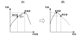
- FIG. 33 is a diagram showing an example of changes in refrigerant amount and performance of the device 1 according to this embodiment. Similar to the example shown in FIG. 19, FIG. 33A is a diagram showing an example of the relationship between the amount of refrigerant and the performance of the device.
- the performance of the device 1 decreases from the optimum value (100% performance) to the current value (80% performance) as the amount of refrigerant decreases.
- the device management apparatus 2 predicts future performance deterioration, as shown in FIG. 33(B).
- the output unit 406 of the device management apparatus 2 transmits information regarding performance, maintenance or replacement (purchase of a new device), etc. to the general-purpose device 5 for the user of the device 1 based on this performance deterioration prediction. By transmitting, it is made to output from the general-purpose device 5 . That is, the output unit 406 provides the user of the device 1 with information based on the amount of refrigerant in the device 1 (information on performance, information on maintenance or replacement) so that the user can easily grasp the state of the device 1. It has a function as a notification part. As a result, the device management system SYS notifies the user of the device 1 of the state of the device 1 such as its performance, and when the performance is degraded, the device 1 is maintained or replaced (purchase of a new device). ) can be recommended.
- the output unit 406 may output from the general-purpose device 5 by transmitting information prompting the general-purpose device 5 to change from the refrigerant R410 with a GWP of 2090 to the refrigerant R32 with a GWP of 675.
- the total GWP amount value can be reduced to be within the total GWP regulation value.
- the output unit 406 may output from the general-purpose device 5 by transmitting information indicating that the refrigerant is to be collected to the general-purpose device 5 . Further, when the refrigerant in the equipment 1 is to be collected, information indicating that the refrigerant is to be collected may be sent to the general-purpose device 5, and information prompting replacement of the equipment may be sent to the general-purpose device 5 to output. .
- the general-purpose device 5 displays this information on the display screen of the general-purpose device 5.
- the general-purpose device 5 may output these pieces of information by voice.
- display examples of the general-purpose device 5 will be described with reference to FIGS.
- FIG. 34 is a diagram showing a first example of display on the general-purpose device 5 according to this embodiment.
- the model name CCC is a device that currently contains the recovery target refrigerant R22.”
- the model name CCC is a device that currently contains the recovery target refrigerant R22.”
- "If you want to replace your device ⁇ here>” is displayed as information prompting you to replace your device.
- a link is set to jump to a site that introduces a replacement model or to a replacement site.
- campaign information or the like to encourage replacement may be displayed, such as "You can purchase at a special price if you want to replace with our product.”
- the display screen of the general-purpose device 5 displays "model BBB is overcharged” as information about the model 1 overcharged with refrigerant among the other models 1 owned by the same owner. Power consumption may be increasing due to overcharging.” is displayed. Further, on the display screen of the general-purpose device 5, "request for maintenance ⁇ here>” is displayed as information prompting maintenance. A link to jump to the site of the maintenance request destination is set in " ⁇ here>".
- FIG. 35 is a diagram showing a second example of display of the general-purpose device according to this embodiment.
- the display screen of the general-purpose device 5 displays information indicating the type of refrigerant charged in each of the three devices 1 installed in the room A and the device to be recovered.
- this is a device for refrigerant recovery
- FIG. 37 is a diagram showing a fourth example of display of the general-purpose device according to this embodiment.
- the display screen of the general-purpose device 5 displays the capacity based on the refrigerant amount of each of the three devices 1 installed in the room A.
- FIG. Here, it is shown that the capacity of two of the three devices 1 is normal at 120%, and the capacity of one device is degraded at 80%.
- "request maintenance ⁇ here>” is displayed as information prompting maintenance in association with the device 1 whose capacity is 80%.
- a link to jump to the site of the maintenance request destination is set in " ⁇ here>".
- the display screen of the general-purpose device 5 also displays information indicating that the capacity of the room A as a whole is sufficient with the total capacity of the three devices 1 .
- the device management device 2 receives from the device 1 having a refrigerant the refrigerant temperature in the device 1, the electrical input (electrical characteristics) of the device 1, and the Device acquisition data 10 (measurement information) indicating measurement results of environmental information around the device 1 is acquired. Then, the device management apparatus 2 estimates the amount of refrigerant in the device 1 based on the acquired device acquisition data 10, the preset device information 20 related to the device 1, and the device installation information 30 related to the installation environment of the device 1. . In addition, the device management device 2 notifies the user (owner, user, etc.) of the device 1 of information based on the estimated amount of refrigerant in the device 1 .
- the device management system SYS estimates the amount of refrigerant in the device 1 and notifies the user of information based on the estimated amount of refrigerant, so that the user can easily grasp the state of the device 1.
- the equipment management device 2 estimates the performance of the equipment 1 based on preset equipment information 20 and equipment installation information 30, and the estimated amount of refrigerant in the equipment 1, and estimates the estimated performance of the equipment 1. to the user of the device 1.
- the device management device 2 notifies the user of the device 1 of information indicating that the refrigerant is a recovery target.
- the device management system SYS estimates the amount of refrigerant in the device 1 and notifies the user of information based on the estimated amount of refrigerant, so that the user can easily grasp the state of the device 1.
- the equipment management system SYS it is possible to create employment for maintenance workers involved in refrigerant recovery work and refrigerant charging work, and employment for development and sales associated with the replacement of the equipment 1.
- an example of an air conditioner capable of switching between cooling operation and heating operation has been described as an example of the device 1, but it may be a dedicated cooling device or a heating dedicated device.
- the refrigerant circuit is for cooling only, excluding the four-way valve 101 in FIG.
- the refrigerant circuit is for heating only, excluding the four-way valve 101 in FIG.
- part or all of the functions of the device management device 2 may be implemented as an integrated circuit such as an LSI (Large Scale Integration). Each function may be individually processorized, or part or all may be integrated and processorized. Also, the method of circuit integration is not limited to LSI, but may be realized by a dedicated circuit or a general-purpose processor. In addition, when an integration circuit technology that replaces LSI appears due to advances in semiconductor technology, an integrated circuit based on this technology may be used.
- LSI Large Scale Integration
Landscapes
- Engineering & Computer Science (AREA)
- Physics & Mathematics (AREA)
- Mechanical Engineering (AREA)
- Thermal Sciences (AREA)
- General Engineering & Computer Science (AREA)
- Air Conditioning Control Device (AREA)
Priority Applications (2)
| Application Number | Priority Date | Filing Date | Title |
|---|---|---|---|
| PCT/JP2022/000881 WO2023135703A1 (ja) | 2022-01-13 | 2022-01-13 | 機器管理システムおよび通知方法 |
| JP2023573713A JP7651016B2 (ja) | 2022-01-13 | 2022-01-13 | 機器管理システムおよび通知方法 |
Applications Claiming Priority (1)
| Application Number | Priority Date | Filing Date | Title |
|---|---|---|---|
| PCT/JP2022/000881 WO2023135703A1 (ja) | 2022-01-13 | 2022-01-13 | 機器管理システムおよび通知方法 |
Publications (1)
| Publication Number | Publication Date |
|---|---|
| WO2023135703A1 true WO2023135703A1 (ja) | 2023-07-20 |
Family
ID=87278667
Family Applications (1)
| Application Number | Title | Priority Date | Filing Date |
|---|---|---|---|
| PCT/JP2022/000881 Ceased WO2023135703A1 (ja) | 2022-01-13 | 2022-01-13 | 機器管理システムおよび通知方法 |
Country Status (2)
| Country | Link |
|---|---|
| JP (1) | JP7651016B2 (https=) |
| WO (1) | WO2023135703A1 (https=) |
Citations (10)
| Publication number | Priority date | Publication date | Assignee | Title |
|---|---|---|---|---|
| JPS4635331Y1 (https=) * | 1969-02-28 | 1971-12-06 | ||
| JP2009079842A (ja) * | 2007-09-26 | 2009-04-16 | Mitsubishi Electric Corp | 冷凍サイクル装置およびその制御方法 |
| WO2010021101A1 (ja) * | 2008-08-19 | 2010-02-25 | ダイキン工業株式会社 | 診断支援装置 |
| WO2010113804A1 (ja) * | 2009-03-30 | 2010-10-07 | 三菱電機株式会社 | 冷凍サイクル装置 |
| WO2011111114A1 (ja) * | 2010-03-12 | 2011-09-15 | 三菱電機株式会社 | 冷凍空調装置 |
| WO2014017161A1 (ja) * | 2012-07-23 | 2014-01-30 | 三菱電機株式会社 | 冷凍空調装置、冷媒漏洩検知装置及び冷媒漏洩検知方法 |
| WO2016174767A1 (ja) * | 2015-04-30 | 2016-11-03 | 三菱電機株式会社 | 冷凍サイクル装置及び冷凍サイクル装置の異常検知システム |
| JP2017026262A (ja) * | 2015-07-27 | 2017-02-02 | 東京電力ホールディングス株式会社 | 計測値処理装置及び計測方法 |
| JP2020180718A (ja) * | 2019-04-23 | 2020-11-05 | 三菱電機株式会社 | 冷媒回収装置 |
| WO2021234810A1 (ja) * | 2020-05-19 | 2021-11-25 | 三菱電機株式会社 | 空気調和システムおよびデータ提供方法 |
Family Cites Families (6)
| Publication number | Priority date | Publication date | Assignee | Title |
|---|---|---|---|---|
| JPH1038354A (ja) * | 1996-07-24 | 1998-02-13 | Toshiba Corp | 空気調和機 |
| JP2010175091A (ja) * | 2009-01-27 | 2010-08-12 | Osaka Gas Co Ltd | エンジン駆動式ヒートポンプ装置 |
| JP5471763B2 (ja) * | 2010-04-19 | 2014-04-16 | 三菱電機株式会社 | 空気調和機、機器システム、情報管理システム、空気調和機の制御方法 |
| JP2013130384A (ja) * | 2011-12-22 | 2013-07-04 | Daikin Industries Ltd | 空気調和装置 |
| JP2015064182A (ja) * | 2013-09-26 | 2015-04-09 | ダイキン工業株式会社 | 空気調和機 |
| JP6297817B2 (ja) * | 2013-11-08 | 2018-03-20 | 東日本旅客鉄道株式会社 | 車両用空気調和機のメンテナンス時期判定方法 |
-
2022
- 2022-01-13 JP JP2023573713A patent/JP7651016B2/ja active Active
- 2022-01-13 WO PCT/JP2022/000881 patent/WO2023135703A1/ja not_active Ceased
Patent Citations (10)
| Publication number | Priority date | Publication date | Assignee | Title |
|---|---|---|---|---|
| JPS4635331Y1 (https=) * | 1969-02-28 | 1971-12-06 | ||
| JP2009079842A (ja) * | 2007-09-26 | 2009-04-16 | Mitsubishi Electric Corp | 冷凍サイクル装置およびその制御方法 |
| WO2010021101A1 (ja) * | 2008-08-19 | 2010-02-25 | ダイキン工業株式会社 | 診断支援装置 |
| WO2010113804A1 (ja) * | 2009-03-30 | 2010-10-07 | 三菱電機株式会社 | 冷凍サイクル装置 |
| WO2011111114A1 (ja) * | 2010-03-12 | 2011-09-15 | 三菱電機株式会社 | 冷凍空調装置 |
| WO2014017161A1 (ja) * | 2012-07-23 | 2014-01-30 | 三菱電機株式会社 | 冷凍空調装置、冷媒漏洩検知装置及び冷媒漏洩検知方法 |
| WO2016174767A1 (ja) * | 2015-04-30 | 2016-11-03 | 三菱電機株式会社 | 冷凍サイクル装置及び冷凍サイクル装置の異常検知システム |
| JP2017026262A (ja) * | 2015-07-27 | 2017-02-02 | 東京電力ホールディングス株式会社 | 計測値処理装置及び計測方法 |
| JP2020180718A (ja) * | 2019-04-23 | 2020-11-05 | 三菱電機株式会社 | 冷媒回収装置 |
| WO2021234810A1 (ja) * | 2020-05-19 | 2021-11-25 | 三菱電機株式会社 | 空気調和システムおよびデータ提供方法 |
Also Published As
| Publication number | Publication date |
|---|---|
| JPWO2023135703A1 (https=) | 2023-07-20 |
| JP7651016B2 (ja) | 2025-03-25 |
Similar Documents
| Publication | Publication Date | Title |
|---|---|---|
| US11769118B2 (en) | Systems and methods for automated diagnostics of HVAC systems | |
| EP2256422B1 (en) | Air conditioning management system, air conditioning system, program, and recording medium | |
| JP4829147B2 (ja) | 空気調和設備 | |
| CN102124277B (zh) | 诊断支援装置 | |
| JP2008510122A (ja) | 冷媒サイクルシステムの監視方法及び監視装置 | |
| EP2071251A1 (en) | Air-conditioning control intermediate device, air-conditioning control system, air-conditioning control method, and air-conditioning control program | |
| CN108758903B (zh) | 空调及其控制方法 | |
| JP2016121867A (ja) | 異常検知装置、空気調和装置、空気調和システム、空調制御装置、異常検知方法、空調制御方法及びプログラム | |
| WO2023135705A1 (ja) | 機器管理システムおよび管理方法 | |
| JP6937261B2 (ja) | 空調制御装置、空調制御方法及びコンピュータプログラム | |
| JP2010048433A (ja) | 診断支援装置 | |
| JP2009115392A (ja) | 省エネルギー制御システム | |
| JP2011214738A (ja) | ダクト循環方式空調システムにおけるエネルギー消費効率管理方法 | |
| CN104089379A (zh) | 地下厂房通风空调系统效能的评定方法 | |
| TW201512607A (zh) | 運轉控制裝置及運轉控制方法 | |
| JP2016017674A (ja) | 外気利用空調システム | |
| JP2009041886A (ja) | 空調熱源設備の性能評価装置 | |
| WO2023135703A1 (ja) | 機器管理システムおよび通知方法 | |
| EP4269911A1 (en) | Air conditioner and operation method thereof | |
| US20240288190A1 (en) | Equipment management system and refrigerant amount estimation method | |
| JP2007240036A (ja) | 空気調和機の診断方法及び診断システム | |
| JP2020076558A (ja) | 空調制御装置、冷媒回路制御装置、検査方法及びプログラム | |
| Othman et al. | Performance evaluation of an actual building air-conditioning system | |
| Dezfouli et al. | Thermal Comfort and Energy Analysis of Fan Coil Unit Cooling Systems in Tropical Buildings | |
| JP2004085088A (ja) | 故障診断装置および故障診断方法 |
Legal Events
| Date | Code | Title | Description |
|---|---|---|---|
| 121 | Ep: the epo has been informed by wipo that ep was designated in this application |
Ref document number: 22920228 Country of ref document: EP Kind code of ref document: A1 |
|
| WWE | Wipo information: entry into national phase |
Ref document number: 2023573713 Country of ref document: JP |
|
| NENP | Non-entry into the national phase |
Ref country code: DE |
|
| 122 | Ep: pct application non-entry in european phase |
Ref document number: 22920228 Country of ref document: EP Kind code of ref document: A1 |