WO2023135703A1 - Device management system and notification method - Google Patents
Device management system and notification method Download PDFInfo
- Publication number
- WO2023135703A1 WO2023135703A1 PCT/JP2022/000881 JP2022000881W WO2023135703A1 WO 2023135703 A1 WO2023135703 A1 WO 2023135703A1 JP 2022000881 W JP2022000881 W JP 2022000881W WO 2023135703 A1 WO2023135703 A1 WO 2023135703A1
- Authority
- WO
- WIPO (PCT)
- Prior art keywords
- refrigerant
- amount
- information
- unit
- equipment
- Prior art date
Links
- 238000000034 method Methods 0.000 title claims description 20
- 239000003507 refrigerant Substances 0.000 claims abstract description 658
- 238000009434 installation Methods 0.000 claims abstract description 81
- 238000005259 measurement Methods 0.000 claims abstract description 46
- 238000012423 maintenance Methods 0.000 claims description 30
- 230000007613 environmental effect Effects 0.000 claims description 25
- 239000002826 coolant Substances 0.000 claims description 18
- 239000007788 liquid Substances 0.000 claims description 10
- 239000010721 machine oil Substances 0.000 claims description 8
- 230000014759 maintenance of location Effects 0.000 claims description 2
- 238000007726 management method Methods 0.000 description 235
- 238000010586 diagram Methods 0.000 description 70
- 230000033228 biological regulation Effects 0.000 description 60
- 238000003860 storage Methods 0.000 description 36
- 238000007689 inspection Methods 0.000 description 33
- 238000004891 communication Methods 0.000 description 32
- RFHAOTPXVQNOHP-UHFFFAOYSA-N fluconazole Chemical compound C1=NC=NN1CC(C=1C(=CC(F)=CC=1)F)(O)CN1C=NC=N1 RFHAOTPXVQNOHP-UHFFFAOYSA-N 0.000 description 32
- 238000001816 cooling Methods 0.000 description 29
- 238000013523 data management Methods 0.000 description 27
- 239000003570 air Substances 0.000 description 26
- 239000007789 gas Substances 0.000 description 26
- 238000010438 heat treatment Methods 0.000 description 24
- 239000012071 phase Substances 0.000 description 17
- 230000007423 decrease Effects 0.000 description 14
- 238000012545 processing Methods 0.000 description 14
- 230000006870 function Effects 0.000 description 12
- 239000003921 oil Substances 0.000 description 12
- 238000011084 recovery Methods 0.000 description 12
- 238000004378 air conditioning Methods 0.000 description 11
- 230000000717 retained effect Effects 0.000 description 11
- XLYOFNOQVPJJNP-UHFFFAOYSA-N water Substances O XLYOFNOQVPJJNP-UHFFFAOYSA-N 0.000 description 11
- 238000005057 refrigeration Methods 0.000 description 8
- 230000006835 compression Effects 0.000 description 7
- 238000007906 compression Methods 0.000 description 7
- 230000006866 deterioration Effects 0.000 description 6
- 230000000694 effects Effects 0.000 description 6
- 239000007791 liquid phase Substances 0.000 description 6
- 230000004044 response Effects 0.000 description 6
- 238000010792 warming Methods 0.000 description 6
- 238000009529 body temperature measurement Methods 0.000 description 5
- 238000004364 calculation method Methods 0.000 description 5
- 238000005516 engineering process Methods 0.000 description 5
- 238000002474 experimental method Methods 0.000 description 5
- 230000008569 process Effects 0.000 description 5
- 230000002829 reductive effect Effects 0.000 description 5
- 230000000007 visual effect Effects 0.000 description 5
- VOPWNXZWBYDODV-UHFFFAOYSA-N Chlorodifluoromethane Chemical compound FC(F)Cl VOPWNXZWBYDODV-UHFFFAOYSA-N 0.000 description 4
- 230000001276 controlling effect Effects 0.000 description 4
- 238000004090 dissolution Methods 0.000 description 4
- 230000007246 mechanism Effects 0.000 description 4
- 230000001681 protective effect Effects 0.000 description 4
- 230000009467 reduction Effects 0.000 description 4
- 230000001105 regulatory effect Effects 0.000 description 4
- 230000003247 decreasing effect Effects 0.000 description 3
- 238000007710 freezing Methods 0.000 description 3
- 230000008014 freezing Effects 0.000 description 3
- 238000009413 insulation Methods 0.000 description 3
- 230000010354 integration Effects 0.000 description 3
- 238000004519 manufacturing process Methods 0.000 description 3
- 238000012802 pre-warming Methods 0.000 description 3
- 230000008929 regeneration Effects 0.000 description 3
- 238000011069 regeneration method Methods 0.000 description 3
- 238000012360 testing method Methods 0.000 description 3
- 239000012080 ambient air Substances 0.000 description 2
- 230000008859 change Effects 0.000 description 2
- 238000007796 conventional method Methods 0.000 description 2
- 230000007812 deficiency Effects 0.000 description 2
- 238000007791 dehumidification Methods 0.000 description 2
- 238000011161 development Methods 0.000 description 2
- 230000018109 developmental process Effects 0.000 description 2
- 238000009826 distribution Methods 0.000 description 2
- 239000005431 greenhouse gas Substances 0.000 description 2
- 230000000737 periodic effect Effects 0.000 description 2
- 239000011150 reinforced concrete Substances 0.000 description 2
- 238000005070 sampling Methods 0.000 description 2
- 230000001052 transient effect Effects 0.000 description 2
- 230000007704 transition Effects 0.000 description 2
- 239000002023 wood Substances 0.000 description 2
- 230000004913 activation Effects 0.000 description 1
- 230000002411 adverse Effects 0.000 description 1
- 230000006399 behavior Effects 0.000 description 1
- 230000015556 catabolic process Effects 0.000 description 1
- 239000003795 chemical substances by application Substances 0.000 description 1
- 238000004140 cleaning Methods 0.000 description 1
- 230000000052 comparative effect Effects 0.000 description 1
- 238000010276 construction Methods 0.000 description 1
- 238000011109 contamination Methods 0.000 description 1
- 230000002950 deficient Effects 0.000 description 1
- 238000006731 degradation reaction Methods 0.000 description 1
- 230000005611 electricity Effects 0.000 description 1
- 230000000670 limiting effect Effects 0.000 description 1
- 230000007257 malfunction Effects 0.000 description 1
- 230000004048 modification Effects 0.000 description 1
- 238000012986 modification Methods 0.000 description 1
- 230000008520 organization Effects 0.000 description 1
- 230000002093 peripheral effect Effects 0.000 description 1
- 238000009419 refurbishment Methods 0.000 description 1
- 230000001172 regenerating effect Effects 0.000 description 1
- 239000004065 semiconductor Substances 0.000 description 1
- 238000004088 simulation Methods 0.000 description 1
- 239000007787 solid Substances 0.000 description 1
Images


Classifications
-
- F—MECHANICAL ENGINEERING; LIGHTING; HEATING; WEAPONS; BLASTING
- F25—REFRIGERATION OR COOLING; COMBINED HEATING AND REFRIGERATION SYSTEMS; HEAT PUMP SYSTEMS; MANUFACTURE OR STORAGE OF ICE; LIQUEFACTION SOLIDIFICATION OF GASES
- F25B—REFRIGERATION MACHINES, PLANTS OR SYSTEMS; COMBINED HEATING AND REFRIGERATION SYSTEMS; HEAT PUMP SYSTEMS
- F25B49/00—Arrangement or mounting of control or safety devices
- F25B49/02—Arrangement or mounting of control or safety devices for compression type machines, plants or systems
Definitions
- This disclosure relates to a device management system and a notification method.
- an air conditioner that estimates the amount of refrigerant in the device by adjusting the temperature so that the temperature of the target space satisfies a predetermined judgment temperature condition and measuring the refrigerant temperature under stable conditions (for example, , see Patent Document 1).
- Patent Document 1 With the conventional technology disclosed in Patent Document 1, it is possible to estimate the amount of refrigerant when the air conditioning load of the outdoor unit and the indoor unit is constant, the compressor frequency is constant, and the refrigeration cycle is stable.
- the air conditioning load on the indoor unit changes depending on factors such as the outside temperature being constant throughout the day, the number of people in the room, and the activity level of the people in the room, an environment where the air conditioning load is constant is realistic. not in Therefore, in the prior art, it is difficult to estimate the amount of refrigerant in an actual use environment, and a special operation is required to estimate the amount of refrigerant. As described above, since there was no mechanism for easily grasping the amount of refrigerant in the device, it was difficult to grasp the state of the device.
- the present disclosure has been made in view of the circumstances described above, and aims to provide a device management system and a notification method that allow users to easily grasp the state of devices.
- a device management system includes a device having a refrigerant, an acquisition unit that acquires measurement information indicating the measurement results of the temperature of the refrigerant in the device, the electrical characteristics of the device, and the environmental information around the device.
- an estimating unit for estimating the amount of refrigerant in the device based on the measurement information acquired by the acquiring unit, preset device information regarding the device, and device installation information regarding the installation environment of the device; a notification unit that notifies a user of the device of information based on the amount of refrigerant in the device estimated by the estimation unit; Prepare.
- the acquisition unit obtains measurement information indicating results of measurement of refrigerant temperature in a device having a refrigerant, electrical characteristics of the device, and environmental information around the device. and an estimating unit, based on the measurement information acquired by the acquiring unit, preset device information related to the device, and device installation information related to the installation environment of the device, the amount of refrigerant in the device and a notification unit notifying a user of the device of information based on the amount of refrigerant in the device estimated by the estimation unit.
- the user can easily grasp the state of the device.
- FIG. 1 is a schematic configuration diagram showing an example of a device management system according to a first embodiment
- FIG. It is a figure which shows an example of the refrigerant circuit of the apparatus which concerns on 1st Embodiment.
- FIG. 3 is an explanatory diagram of measurement locations of temperature measurement points shown in FIG. 2 according to the first embodiment; The figure which shows an example of the refrigerant circuit of the multi-type air conditioner which concerns on 1st Embodiment.
- FIG. 4 is a diagram showing an example of a Mollier diagram immediately after activation according to the first embodiment; The figure which shows an example of the Mollier diagram at the time of the stability which concerns on 1st Embodiment. The figure which shows an example of the electric circuit of the apparatus which concerns on 1st Embodiment.
- FIG. 4 is a diagram showing an example of data items of device acquisition data according to the first embodiment
- FIG. FIG. 5 is a diagram showing an example of device acquisition data transmitted by the device according to the first embodiment
- 1 is a schematic block diagram showing an example configuration of a device management apparatus according to a first embodiment
- FIG. 4 is a flowchart showing an example of refrigerant amount estimation processing according to the first embodiment
- FIG. 4 is an explanatory diagram showing an example of a method for calculating an estimated amount of refrigerant according to the first embodiment
- the schematic block diagram which shows an example of the equipment management system which concerns on 2nd Embodiment.
- FIG. 11 is a diagram showing an example of time-series data of each of a plurality of devices held by a device management apparatus according to the third embodiment;
- the schematic block diagram which shows an example of the equipment management system which concerns on 5th Embodiment.
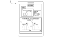
- FIG. 11 is a diagram showing a display example displayed on a general-purpose device according to the fifth embodiment;
- FIG. 11 is a diagram showing a display example displayed on a general-purpose device according to the sixth embodiment;
- FIG. 11 is a schematic configuration diagram showing an example of a device management system according to an eighth embodiment;
- FIG. 11 is a schematic block diagram showing an example of the configuration of a device management apparatus according to an eighth embodiment;
- FIG. 12 is a diagram showing an example of device refrigerant data according to the eighth embodiment;
- FIG. 14 is a diagram showing another data example of device refrigerant data according to the eighth embodiment; The figure which shows the 1st example of the display of the information regarding the refrigerant
- FIG. 21 is a schematic configuration diagram showing an example of a device management system according to a ninth embodiment;
- FIG. 21 is a diagram showing an example of device refrigerant data according to the ninth embodiment;
- FIG. 12 is a diagram showing an example of changes in the refrigerant amount and performance of the device according to the tenth embodiment;
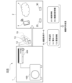
- FIG. 1 is a schematic configuration diagram showing an example of a device management system according to this embodiment.
- the device management system SYS shown in this figure includes a device 1 having a refrigerant and a device management device 2 capable of communicating with the device 1 .
- the device 1 is, for example, an air conditioner that includes an outdoor unit 100 and an indoor unit 200 .
- the device management device 2 is a data management destination that stores communication data from the device 1 and estimates the amount of refrigerant in the device 1 .
- the external terminal 3 and the cloud 4 are exemplified as the device management device 2 .
- the external terminal 3 is a terminal device such as a smartphone or a PC (Personal Computer). In addition to communicating with the device 1 , the external terminal 3 may communicate with the cloud 4 and transmit communication data from the device 1 to the cloud 4 .
- the cloud 4 is a group of arithmetic processing units connected via a communication network such as a public line.
- the device management device 2 may be the external terminal 3 or the cloud 4 .
- the device management system SYS communicates with the device 1 based on device acquisition data 10 acquired by the device 1, device information 20 regarding the device 1, and device installation information 30 regarding the installation environment in which the device 1 is installed.
- a connected external terminal 3 or a device management device 2 such as a cloud 4 estimates the amount of refrigerant in the device 1 .
- the device acquisition data 10 includes a measured value of the coolant temperature in the device 1 (hereinafter referred to as “refrigerant temperature 11”) and a measured value of the electrical characteristics in the device 1 (hereinafter referred to as “electrical input 12”). ) and measurement information such as a measured value of environmental information such as temperature or humidity around the device 1 (hereinafter referred to as “environmental information 13”).
- the device 1 transmits device acquisition data 10 to the device management apparatus 2 .
- the device management device 2 acquires the device acquisition data 10 transmitted from the device 1.
- the device management apparatus 2 also has preset device information 20 and device installation information 30 .
- the device information 20 includes inspection data before shipment.
- the device information 20 includes inspection data (stationary data or time-series data) of refrigerant temperature in the device 1 under specific inspection conditions, electrical characteristics in the device 1, or environmental information, inspection conditions, specifications (configuration) of the device 1 at the time of inspection.
- the device installation information 30 includes the environment or installation state of the place where the device is installed. Details of the device acquisition data 10, the device information 20, and the device installation information 30 will be described later.
- FIG. 2 is a diagram showing an example of a refrigerant circuit of equipment according to the present embodiment.
- the outdoor unit 100 and the indoor unit 200 are connected by inside/outside connection pipes 301 and 302 .
- a refrigerant in a gaseous state passes through the internal/external connection pipe 301 .
- a coolant in a liquid state passes through the internal/external connection pipe 302 .
- the four-way valve 101 provided in the outdoor unit 100 to switch the circulation direction of the refrigerant, the heating operation and the cooling operation are switched.
- the direction of the solid line arrow indicates the direction of refrigerant flow during cooling operation, and the direction of the broken line arrow indicates the direction of refrigerant flow during heating operation.
- gaseous refrigerant compressed by the compressor 102 of the outdoor unit 100 flows through the four-way valve 101 and the internal/external connection pipe 301 to the indoor heat exchanger 201 of the indoor unit 200 .
- the refrigerant in the indoor heat exchanger 201 exchanges heat with the ambient air to warm the ambient air.
- the refrigerant that has become liquid due to heat exchange flows through the internal/external connection pipe 302 to the expansion valve 103 of the outdoor unit 100 , and flows through the expansion valve 103 into the outdoor heat exchanger 104 .
- the refrigerant in the outdoor heat exchanger 104 exchanges heat with the surrounding air.
- Refrigerant in a gaseous state through heat exchange passes through the four-way valve 101 and returns to the compressor 102 .
- gaseous refrigerant compressed by the compressor 102 of the outdoor unit 100 flows through the four-way valve 101 into the outdoor heat exchanger 104 .
- the refrigerant in the outdoor heat exchanger 104 exchanges heat with the surrounding air.
- the refrigerant that has become liquid due to heat exchange flows through the expansion valve 103 and the internal/external connecting pipe 302 into the indoor heat exchanger 201 of the indoor unit 200 .
- the refrigerant in the indoor heat exchanger 201 exchanges heat with the surrounding air to cool the surrounding air.
- the refrigerant that has become gaseous due to heat exchange returns to the compressor 102 of the outdoor unit 100 through the internal/external connection pipe 301 and the four-way valve 101 .
- FIG. 3 is an explanatory diagram of the temperature measurement points T1 to T8 shown in FIG.
- a temperature sensor is provided on each of the outlet side and the inlet side of the compressor 102, the outlet side measuring point T1 is the outlet side measuring point, and the inlet side measuring point T8 is the suction temperature measuring point.
- the expansion valve 103 and the outdoor heat exchanger 104 of the outdoor unit 100 and the indoor heat exchanger 201 of the indoor unit 200 are each provided with three points: the outlet side, the inlet side, and the middle point between the outlet and the inlet. is provided with a temperature sensor.
- the outdoor heat exchanger 104 functions as a condenser during cooling operation.
- Measurement points T2, T2-3, and T3 are measurement points for the inlet temperature, intermediate temperature, and outlet temperature of the condenser during cooling operation, respectively.
- the outdoor heat exchanger 104 functions as an evaporator during heating operation.
- Measurement points T2, T2-3, and T3 are measurement points for the outlet temperature, intermediate temperature, and inlet temperature of the evaporator during heating operation, respectively.
- the measurement point T4 serves as a measurement point for the inlet temperature of the expansion valve 103 during cooling operation, and for the outlet temperature of the expansion valve 103 during heating operation.
- the measurement point T5 serves as a measurement point for the outlet temperature of the expansion valve 103 during cooling operation and for the inlet temperature of the expansion valve 103 during heating operation.
- the device 1 may be a multi-type air conditioner (a so-called package air conditioner) in which a plurality of indoor units 200 are connected to one outdoor unit 100.
- a multi-type air conditioner a so-called package air conditioner
- the number of devices 1 is basically one for one outdoor unit 100 regardless of whether there is one indoor unit 200 or a plurality of indoor units 200 .
- the enthalpy decreases due to heat exchange with the air by the condenser. If the amount of refrigerant gas and the amount of heat exchange in the condenser are sufficient, the measurement point T3 transitions into the liquid phase region (see FIG. 6). On the other hand, if the amount of refrigerant gas is insufficient, heat exchange in the condenser and evaporator will be insufficient.
- FIG. 7 is a diagram showing an example of an electric circuit of the device 1 according to this embodiment.
- the same reference numerals are given to the components corresponding to the parts in FIG.
- the outdoor unit control unit 110 controls switching of the refrigerant flow direction in the four-way valve 101, controls the compressor 102, controls the opening degree of the expansion valve 103, and controls the outdoor fan 105 that blows air to the outdoor heat exchanger 104. Rotation control, etc.
- the compressor 102 includes a compression section 102a and a compressor motor 102b.
- Compression part 102a has a compression mechanism such as a rotary type or a scroll type, compresses the refrigerant sucked from the inlet side, and discharges it from the outlet side.
- Compressor motor 102b includes a three-phase motor whose rotation can be controlled by inverter 120, and drives the compression mechanism of compression section 102a. By controlling the inverter 120, the outdoor unit control section 110 controls the rotation of the compressor motor 102b to control the compression mechanism of the compression section 102a.
- the indoor unit 200 includes an indoor unit control section 210.
- the indoor unit control unit 210 includes a microcomputer, controls each unit of the indoor unit 200, and acquires measurement values of various sensors provided in the indoor unit 200. For example, the indoor unit control unit 210 acquires the measured values of the temperature sensors provided at the refrigerant temperature measurement points T6, T6-7, and T7 described with reference to FIGS. 2 and 3, respectively.
- the indoor unit control unit 210 also controls the rotation of the indoor fan 202 that blows air to the indoor heat exchanger 201, and the like.
- the air conditioning load of the outdoor and indoor units is constant like in a test room.
- the air conditioning load applied to the outdoor unit changes due to the outside temperature not being constant throughout the day.
- the air conditioning load applied to the indoor unit changes depending on the number of people in the room or their activity status.
- the device management device 2 (external The terminal 3 or the cloud 4) estimates the amount of refrigerant in the device 1.
- the equipment management system SYS can accurately estimate the amount of refrigerant in the equipment 1 in the actual use environment without requiring any special operation. A detailed description will be given below.
- Temperature sensors may also be provided in the internal/external connection pipes 301 and 302, and the temperature of the internal/external connection pipe 301 (for example, inlet temperature and outlet temperature) may be included in the coolant temperature 11.
- the coolant temperature 11 is not limited to the temperature at the location described above, and may include the coolant temperature at any location that can be acquired by the device 1 .
- the refrigerant temperature 11 includes measured values of the refrigerant temperature at more points, the higher the refrigerant amount estimation accuracy.
- the environmental information 13 includes, for example, ambient temperature (outdoor temperature, indoor temperature) and humidity (outdoor humidity, indoor humidity) acquired by the outdoor unit 100 and the indoor unit 200 .
- the environment information 13 may include all of the above data items, or may include some of them.
- the environment information 13 preferably includes at least room temperature.
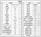
- the common items include the specifications (configuration) of the device 1 at the time of inspection.
- common items include date and time of inspection (No. 1), test room used for inspection (No. 2), manufacturing information and product specifications of the inspected device 1, and the like.
- the manufacturing information includes lot number (No. 3), manufacturing year (No. 6), and the like.
- the model No. 4
- capacity No.
- the receiver is provided, for example, in the vicinity of the connecting portion between the expansion valve 103 of the outdoor unit 100 and the internal/external connection pipe 302 .
- This receiver is provided to store surplus refrigerant because the required amount of refrigerant differs between cooling operation and heating operation.
- the internal volume of the outdoor unit 100 is larger than that of the indoor unit 200, and the amount of refrigerant in the indoor unit 200 serving as a condenser during heating operation is smaller than that of the outdoor unit 100 during cooling operation.
- No. of inspection data items 1 to No. Item 5 is a common inspection condition regardless of the type of equipment 1 .
- the common inspection conditions include test conditions (for example, cooling standard or heating standard), outdoor DB (Dry Bulb), outdoor WB (Wet Bulb), indoor DB, and indoor WB.
- the device information 20 may include all of the above data items, or may include some of them.
- the device information 20 preferably includes at least the refrigerant type and the volume of space through which the refrigerant can flow.
- the volume of the space through which the refrigerant can flow is the internal volume of the compressor 102, the internal volume of the outdoor heat exchanger 104, the internal volume of the indoor heat exchanger 201, the internal volume of the receiver, and the like.
- the volume of the space through which the refrigerant can flow may include part of the internal volume of the compressor 102, the internal volume of the outdoor heat exchanger 104, the internal volume of the indoor heat exchanger 201, and the internal volume of the receiver. and all may be included.
- the device information 20 may include any measurable information at the time of inspection. The more data items included in the device information 20, the higher the refrigerant amount estimation accuracy.
- the device installation information 30 includes the position (latitude, longitude) of the installation location of the device 1, the building specifications, the installation direction (facing north, facing south, etc.), the installation method of the outdoor unit 100 (on the roof, on the ground, on the ceiling, etc.). hanging, wall surface, etc.), the height of the indoor unit 200 (height from the floor surface), the size of the indoor space, the length and diameter of the internal and external connection pipes 301 and 302 that connect the outdoor unit 100 and the indoor unit 200,
- the height difference (indoor/outdoor height difference) between the outdoor unit 100 and the indoor unit 200 is included as information such as the installation location or the installation environment.
- the indoor/outdoor height difference is the height difference between the position where the inside/outside connection pipes 301 and 302 are connected to the outdoor unit 100 and the position where the inside/outside connection pipes 301 and 302 are connected to the indoor unit 200 .
- the device installation information 30 may include all of the above data items, or may include some of them.
- the equipment installation information 30 preferably includes the length and diameter of the internal/external connection pipes 301 and 302, which are related to the volume of the space through which the refrigerant can flow.
- the device installation information 30 may include any information other than the above data items regarding the environment or installation state of the installation location. The more data items included in the equipment installation information 30, the higher the refrigerant amount estimation accuracy.
- the installation location or installation environment of the device 1 differs depending on the user. If the installation location or installation environment is different, the estimation of the refrigerant amount is also affected. For example, regarding the installation location of the device 1, when the outdoor unit 100 is installed on the first floor, when the indoor unit 200 is installed on the first floor and when the indoor unit 200 is installed on the third floor, the outdoor unit The height of the indoor unit 200 with respect to 100 is generally different by about 5m. Therefore, even if the amount of refrigerant in the device 1 excluding the internal/external connection pipes 301 and 302 is the same, the lengths of the internal/external connection pipes 301 and 302 are different, so it is assumed that different behaviors will be exhibited in terms of the refrigeration cycle. . Therefore, it is conceivable that the installation location of the device 1 affects the estimation of the amount of refrigerant.
- the lengths of the internal/external connection pipes 301 and 302 may differ. In that case, since the refrigerant is distributed in the internal/external connection pipes 301 and 302, if the additional refrigerant is not charged for the length of the internal/external connection pipes 301 and 302, the amount of refrigerant in the device 1 excluding the internal/external connection pipes will be reduced. It is conceivable that it will decrease in general and cause a gas shortage. Regarding the installation environment of the device 1, the lengths of the internal/external connection pipes 301 and 302 differ depending on whether the outdoor unit 100 is suspended from the ceiling, placed on the ground, or placed on the roof.
- the air conditioning load differs depending on whether it is facing south and exposed to direct sunlight or facing north and is in the shade, which affects the refrigeration cycle. Therefore, it is conceivable that the installation environment of the device 1 similarly affects the estimation of the amount of refrigerant.
- the insulation performance differs depending on whether the building in which the device 1 is installed is made of wood or reinforced concrete. For example, if the building is made of wood and has low heat insulation, the air conditioning load will increase, which may affect the refrigeration cycle and affect the estimation of the amount of refrigerant.
- the device management apparatus 2 uses the device installation information 30 to estimate the amount of refrigerant according to the installation location or installation environment of the device 1 without fixing the installation location or installation environment of the device 1. be able to.
- FIG. 12 is a schematic block diagram showing an example of the configuration of the device management apparatus 2 according to this embodiment.
- the device management device 2 is the external terminal 3 or the cloud 4 as described above, and includes, for example, a storage unit 401 , a communication unit 402 and a processing unit 403 .
- the storage unit 401 stores control programs for controlling each unit of the device management apparatus 2 and various data.
- the storage unit 401 includes DRAM (Dynamic Random Access Memory), EEPROM (Electrically Erasable Programmable Read Only Memory), Flash ROM, HDD (Hard Disk Drive), SSD (Solid State Drive) ), etc.
- the device information 20 (see FIG. 10) and the device installation information 30 (see FIG. 11) are pre-stored in the storage unit 401 .
- the communication unit 402 performs data communication with the device 1 or other devices by wireless communication.
- the communication unit 402 connects to a communication network such as a wireless LAN (Local Area Network) or the Internet by wireless communication, and performs data communication with the device 1 or other devices. do.
- the communication unit 402 may also support wired communication.
- the processing unit 403 has a CPU (Central Processing Unit) executing a control program stored in the storage unit 401 to perform a refrigerant amount estimation process for estimating the amount of refrigerant. 405 and an output unit 406 .
- the acquisition unit 404 acquires the device acquisition data 10 (see FIG. 8) from the device 1 (for example, the indoor unit 200) via the communication unit 402 and stores it in the storage unit 401.
- FIG. Estimating unit 405 estimates the amount of refrigerant in device 1 .
- the estimated refrigerant amount is referred to as "estimated refrigerant amount 40".
- the estimation unit 405 calculates the estimated refrigerant amount 40 in the device 1 based on the device acquisition data 10 acquired by the acquisition unit 404 and the device information 20 and the device installation information 30 stored in the storage unit 401. calculate.
- the output unit 406 outputs the estimation result of the refrigerant amount by the estimation unit 405 .
- FIG. 13 is a flowchart showing an example of refrigerant amount estimation processing according to the present embodiment.
- the device 1 (for example, the indoor unit 200) sends the device acquired data 10 to the device management device 2, either voluntarily or passively by the user who operates the device 1, periodically (for example, every five minutes). Send.
- the device management apparatus 2 receives the device acquisition data 10 transmitted from the device 1 (step S101).
- the device management apparatus 2 Upon receiving the device acquisition data 10 transmitted from the device 1, the device management apparatus 2 acquires the device acquisition data 10 each time it is received, and stores and accumulates it in the storage unit 401 (step S103).
- the device management device 2 estimates the amount of refrigerant in the device 1 at any timing, in addition to internal periodic processing.
- the device management apparatus 2 determines whether or not it is time to estimate the amount of refrigerant (step S105). If it is not the refrigerant amount estimation timing (NO), the process returns to step S101, and the device management apparatus 2 periodically receives the device acquisition data 10 from the device 1 (step S103).
- the device management device 2 estimates the amount of refrigerant in the device 1 (step S107). Specifically, the equipment management apparatus 2 calculates the estimated refrigerant amount 40 based on the accumulated equipment acquisition data 10 and the equipment information 20 and the equipment installation information 30 held internally in advance. Then, the device management device 2 outputs the estimated refrigerant amount (estimated refrigerant amount 40) (step S109).
- FIG. 14 is an explanatory diagram showing an example of a method for calculating an estimated amount of refrigerant according to this embodiment.
- the equipment management apparatus 2 calculates an estimated refrigerant amount 40 by summing a converted refrigerant amount 41, a dissolved refrigerant amount 42, and a retained refrigerant amount 43, for example.
- the estimated refrigerant amount 40 may be set directly if it can be determined from the refrigerant charging operation or the like.
- the equivalent refrigerant amount 41 is the amount of refrigerant in the main refrigerant state in each part that constitutes the device 1 .
- the converted refrigerant amount 41 indicates the amount of refrigerant in the gas phase portion.
- the converted refrigerant amount 41 indicates the amount of refrigerant in the gas phase portion.
- the converted refrigerant amount 41 indicates the refrigerant amount using the two-phase average density.
- the equivalent refrigerant amount 41 is calculated by multiplying the internal volume of each part of the device 1 by the refrigerant density.
- a converted refrigerant amount 41 is included in the internal volume 31 of the internal/external connection pipes 301 and 302 determined from the equipment installation information 30 (the length and diameter of the internal/external connection pipes 301 and 302) and the equipment information 20. It is calculated by multiplying the internal volume 51 of each part in the equipment 1 and the refrigerant density 50 in each part.
- the refrigerant density in each component can be obtained from the relationship between pressure and density by converting the refrigerant temperature of the equipment acquisition data 10 into pressure.
- the relationship between pressure and density is determined by the type of refrigerant.
- the data of the refrigerant pressure can be directly acquired from the device 1, it can be obtained based on the acquired refrigerant pressure or pressure data.
- Each component described here is a component having a space in which a refrigerant can flow among the components constituting the device 1, and includes, for example, the compressor 102, the outdoor heat exchanger 104, the indoor heat exchanger 201, the receiver, the internal and external They are connecting pipes 301 and 302 and the like.
- the dissolved refrigerant amount 42 is the amount of refrigerant dissolved in the refrigerating machine oil used in the equipment 1 .
- the dissolved refrigerant amount 42 is calculated by summing up the product of the retained oil amount 52 of each part and the oil dissolution ratio 53 of each part for each part.
- the total amount of oil in the equipment 1 is the value of the oil amount in the equipment information 20 shown in FIG.
- a retained oil amount 52 remaining in each component out of the amount of oil in the equipment 1 is determined based on the equipment acquisition data 10, the equipment information 20, and the equipment installation information 30 according to the operating conditions (cooling, heating, etc.). obtained by experiments or numerical calculations.
- the device information 20 further includes a retained oil amount 52 for each component determined by this experiment or numerical calculation.
- the oil dissolution ratio 53 of each component can be calculated using a Daniel chart showing the amount of refrigerant dissolved in refrigerating machine oil according to temperature and pressure by an experimental method.
- the current oil dissolution ratio 53 of each part can be calculated using the measured value of the refrigerant temperature of each part included in the device acquisition data 10 and the Daniel chart. When obtaining using a Daniel chart, it may be calculated by an approximation formula.
- the retained oil amount 52 of each part may target only the parts that have a large internal volume and in which the refrigerating machine oil tends to stagnate, and may exclude the parts in which the refrigerating machine oil is less likely to stagnate.
- refrigerating machine oil tends to stay in the compressor 102, the outdoor heat exchanger 104, and the indoor heat exchanger 201 and is present in large amounts.
- the retained refrigerant amount 43 is the amount of liquid refrigerant retained in each component (receiver, internal/external connection pipes 301, 302, etc.) in the gas-liquid two-phase region. If the cross-sectional area of the coolant channel of each component is small, the flow velocity of the coolant becomes faster, making it difficult for the coolant to stagnate. Therefore, for example, as shown in FIG. 14, the amount of retained refrigerant 43 circulates through the cross-sectional area of the refrigerant flow path of each component and inside the device 1 based on the device acquisition data 10, the device information 20, and the device installation information 30. It can be obtained by experiments or numerical calculations depending on the refrigerant flow rate.
- the flow rate of refrigerant circulating in the device 1 is determined by the frequency of the compressor 102 and the density of the suctioned refrigerant.
- the suctioned refrigerant density can be uniquely obtained from the amount of heat exchange between the condenser and the evaporator in the equipment 1 . Note that it can also be obtained from the intake temperature or pressure acquired by the device 1 .
- the amount of heat exchanged between the condenser and the evaporator is determined by the outdoor or indoor environmental load, and can be obtained from the device acquisition data 10 and the device installation information 30 at this time.
- the device management device 2 controls the refrigerant temperature in the device 1, the electrical input (electrical characteristics) of the device 1, and the environmental information around the device 1. Acquires device acquisition data 10 (measurement information) indicating the measurement result of . Then, the equipment management apparatus 2 calculates an estimated refrigerant amount 40 based on the obtained equipment acquisition data 10 and preset equipment information 20 and equipment installation information 30 to estimate the amount of refrigerant in the equipment 1 . In addition, for example, the estimation of the refrigerant amount may be performed by the external terminal 3 , the cloud 4 , or the cloud 4 via the external terminal 3 .
- the equipment management system SYS can estimate the amount of refrigerant in the equipment 1 during normal operation, unlike the conventional method of estimating the amount of refrigerant. That is, the equipment management system SYS can accurately estimate the amount of refrigerant in the equipment in the actual use environment without requiring any special operation.
- the device information 20 includes at least information about the volume of the space through which the refrigerant can flow within the device 1 and the type of refrigerant possessed by the device 1 .
- the equipment management system SYS can estimate the amount of refrigerant in the space in which the refrigerant can flow in the equipment 1 according to the refrigerant type.
- the device management device 2 calculates the amount of refrigerant in the device 1 based on the volume of the space through which the refrigerant can flow in the device 1 and the refrigerant density determined based on the refrigerant temperature and refrigerant type in the device 1 .
- the device management system SYS can accurately estimate the amount of refrigerant in the device 1 .
- the equipment management device 2 further calculates the amount of refrigerant dissolved in the refrigerating machine oil used in the equipment 1 (dissolved refrigerant amount 42) and the amount of refrigerant in the liquid stagnant portion (accumulated refrigerant amount 43) in the equipment 1.
- the amount of refrigerant is calculated. That is, the equipment management apparatus 2 calculates the estimated refrigerant amount 40 by summing the converted refrigerant amount 41 , the dissolved refrigerant amount 42 , and the retained refrigerant amount 43 .
- the equipment management system SYS can accurately estimate the amount of refrigerant in the equipment 1 even in a transient phenomenon.
- an outdoor unit 100 including a compressor 102, an outdoor heat exchanger 104, and an expansion valve 103, and an indoor unit 200 including an indoor heat exchanger 201 use internal/external connection pipes 301 and 302 through which refrigerant flows.
- the device installation information 30 includes at least information about the volume of the internal/external connection pipes 301 and 302 (for example, the diameter and length of the internal/external connection pipes 301 and 302).
- the device management system SYS can accurately estimate the amount of refrigerant in the device 1, including the connecting portion between the outdoor unit 100 and the indoor unit 200.
- the environmental information around the device 1 includes at least information about the ambient temperature of the device 1 .
- the ambient temperature is the temperature (indoor temperature) of the environment (indoor) in which the indoor unit 200 is installed or the temperature (outdoor temperature) of the environment (outdoor) in which the outdoor unit 100 is installed.
- the device management system SYS can accurately estimate the amount of refrigerant in the device 1 in consideration of the ambient temperature of the device 1 .
- the device management system SYS is equipped with an external terminal 3 or a cloud 4 capable of communicating with the device 1 as the device management device 2 . Accordingly, the device management system SYS can be easily applied to various devices 1 because the device 1 does not need to have a function necessary for estimating the amount of refrigerant.
- the refrigerant amount estimation method for estimating the refrigerant amount in the device 1 having the refrigerant is such that the device management device 2 determines the refrigerant temperature in the device 1, the electrical input of the device 1 ( electrical characteristics), and device acquired data 10 (measurement information) indicating the measurement result of environmental information around the device 1; acquired device acquired data 10; and estimating the amount of refrigerant in the device 1 based on the installation information 30 .
- the equipment management system SYS can estimate the amount of refrigerant in the equipment 1 during normal operation, unlike the conventional method of estimating the amount of refrigerant. That is, the equipment management system SYS can accurately estimate the amount of refrigerant in the equipment in the actual use environment without requiring any special operation.
- FIG. 15 is a schematic configuration diagram showing an example of a device management system according to this embodiment.
- the device management system SYS shown in this figure includes a plurality of devices 1 having refrigerant and a device management device 2 capable of communicating with each device 1 .
- this figure shows an example in which there are three devices 1, the number may be two or four or more.
- the configuration and operation of the refrigerant amount estimation process in the equipment management system SYS are the same as in the first embodiment.
- the acquisition unit 404 acquires the device acquisition data 10 from each of the multiple devices 1 .
- the estimation unit 405 calculates the amount of refrigerant (total amount of refrigerant) in the plurality of devices 1 based on the device acquisition data 10 acquired by the acquisition unit 404 and the preset device information 20 and device installation information 30 .
- the device management system SYS collectively manages the device acquisition data 10, the device information 20, and the device installation information 30 of each of the plurality of devices 1, thereby controlling the total refrigerant amount (refrigerant amount) of the plurality of devices 1. total amount) can be estimated.
- the equipment management system SYS can also individually estimate the amount of refrigerant for each of the plurality of equipment 1 .
- the basic configuration of the equipment management system SYS according to this embodiment is the same as in the first and second embodiments. Also, the basic operation of the equipment management system SYS according to this embodiment is the same as in the first and second embodiments, but differs in that the refrigerant management value is used.
- refrigerants with a high global warming potential tend to gradually reduce their use in the market.
- GWP of R410a is 2090 and GWP of R32 is 675.
- R410a is a refrigerant that has three times as much global warming effect as R32. Therefore, when R410a is used, the impact on the global environment (global warming) is equalized by limiting the amount of refrigerant to one third of the amount of refrigerant when using R32.
- the amount of refrigerant whose use is restricted in the device 1 for each type of refrigerant is the above-mentioned refrigerant management value.
- the refrigerant management value is calculated as the sum of the charged refrigerant amount at the time of shipment of the device 1 and the additional charged refrigerant amount required for the device 1 .
- FIG. 16 is a schematic configuration diagram showing an example of a device management system according to this embodiment.
- the equipment management device 2 estimates the amount of refrigerant in the equipment 1 based on the equipment acquisition data 10, the equipment information 20, and the equipment installation information 30, and calculates the estimated refrigerant amount (estimated refrigerant amount 40) and the refrigerant management value. can be compared to determine whether the amount of refrigerant in the device 1 is excessive or insufficient.
- the configuration is such that the amount of refrigerant in the device 1 is estimated at an arbitrary timing, so time-series data as shown in FIG. 17 can be retained.
- the estimating unit 405 calculates the refrigerant management value of the device 1 based on the sum of the charging refrigerant amount at the time of shipment of the device 1 and the additional charging refrigerant amount required for the device 1 . Then, the estimating unit 405 compares the estimated refrigerant amount value in the device 1 with the refrigerant management value of the device 1, and determines whether the amount of refrigerant in the device is excessive or insufficient.
- FIG. 17 is a diagram showing an example of time-series data held by the device management apparatus. This figure shows time-series data of the refrigerant management value and the estimated refrigerant amount value at each time.
- the estimated refrigerant amount value from time t0 to t1 is an estimated value of the refrigerant amount filled in the device 1 at the time of installation, and corresponds to the charged refrigerant amount of the device 1 at the time of shipment.
- the estimated refrigerant amount value is close to the refrigerant management value at time t2.
- the estimated refrigerant amount after time t3 decreases, and then after time t4, the estimated refrigerant amount reaches a certain value. value stabilizes.
- the device management device 2 can determine whether the amount of refrigerant in the device 1 is excessive or insufficient by comparing the difference between the refrigerant management value and the estimated refrigerant amount value based on the time-series data shown in FIG.
- the equipment management device 2 can grasp that the refrigerant gas is leaking.
- the device management device 2 determines whether the amount of refrigerant in the device 1 is excessive or deficient at an arbitrary timing with high determination accuracy (for example, after 30 minutes have passed since the start of the device 1), or periodically (for example, (every one minute), and output as instantaneous values or time-series data.
- the equipment management device 2 simply determines whether the amount of refrigerant in the equipment 1 is excessive or insufficient when judging whether the amount of refrigerant is excessive or insufficient for one equipment 1 .
- the device management device 2 can also manage the amount of refrigerant used in the market when judging whether the amount of refrigerant is excessive or insufficient for a plurality of devices 1 .
- FIG. 18 is a diagram showing an example of time-series data of each of a plurality of devices 1 (here, device A, device B, and device C) held by the device management apparatus 2. As shown in FIG.
- the device management apparatus 2 obtains the sum of the estimated refrigerant amount values at time t0 when each of the plurality of devices 1 is installed, so that the device management apparatus 2 can grasp the total refrigerant amount of the plurality of devices 1 at the time of installation. can.
- only device A is additionally charged with refrigerant between time t1 and time t2, and the refrigerant gas in device A decreases between time t3 and time t4, so refrigerant leakage occurs.
- device C has refrigerant leakage between time t2 and time t3.
- the devices A to C were removed at time t4, it can be seen that the rest of the refrigerant, excluding the refrigerant leaked from the devices A and C, could be recovered.
- the recovered refrigerant does not affect the environment even if it is replaced with a new device 1 having the same amount of refrigerant.
- the device 1 having the refrigerant can be used continuously.
- the new device 1 uses a different type of refrigerant, it can be replaced without affecting the environment by applying a refrigerant control value according to the type of refrigerant.
- the basic configuration of the equipment management system SYS according to this embodiment is the same as in the first and second embodiments. Further, the basic operation of the device management system SYS according to this embodiment is the same as in the first and second embodiments, but the performance of the device 1 is estimated based on the estimated refrigerant amount 40 and the estimated The difference is that the obtained operating performance is compared with the device information 20 of the device 1, published inspection data, catalog information, or the like.
- the catalog information is information described in the catalog of the manufacturer of the device 1 and includes, for example, numerical values regarding the specifications of the device 1 .
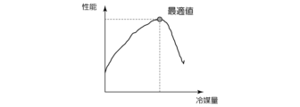
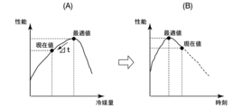
- FIG. 19 is a diagram showing an example of the relationship between the amount of refrigerant and the performance of equipment according to this embodiment.
- FIG. 20 is a diagram showing an example of comparison with catalog values for the relationship between the performance of the device and the air temperature according to this embodiment.
- the performance of the equipment 1 indicates, for example, operation performance such as cooling, heating, dehumidification, and freezing. Note that the power consumption of the device 1 may be used as the performance of the device 1 .
- the equipment management device 2 calculates the estimated refrigerant amount 40 of the equipment 1 having the characteristics as shown in FIG. Then, the device management apparatus 2 summarizes the calculated performance of the device 1 as characteristics as shown in FIG. 19 is determined by numerical calculation based on the device information 20 and the device installation information 30. FIG. Similarly, the example shown in FIG. 20 is also determined by numerical calculation based on the device information 20, published inspection data, or catalog information. The inspection data or catalog information to be published is included in the equipment information 20 .
- the device management system SYS estimates the performance of the device 1 based on the device information 20, the device installation information 30, and the estimated amount of refrigerant, thereby grasping the performance of the device 1. can do. Further, when the device management system SYS has a plurality of devices 1, the device management system SYS can grasp the performance of each device 1 as well as the performance of the plurality of devices 1 as a whole. Furthermore, the device management system SYS compares the estimated performance of each device 1 or the overall performance of a plurality of devices 1 with the device information 20, published inspection data, or catalog information, thereby Performance can be evaluated, and, for example, the adequacy of the performance of the device 1 can be grasped.
- the basic configuration of the equipment management system SYS according to this embodiment is similar to that of the first and second embodiments, but differs in that a general-purpose device is further provided.
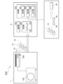
- FIG. 21 is a schematic configuration diagram showing an example of a device management system according to this embodiment.
- the equipment management apparatus 2 is configured to be able to communicate with the general-purpose device 5 .
- the general-purpose device 5 is an example of an external device, such as a device having a display screen (eg, smart phone, PC) or a device that emits sound (eg, wireless earphones).
- the basic operation of the equipment management system SYS is the same as in the first to fourth embodiments, but the estimated refrigerant amount 40 of the equipment 1 calculated by the equipment management device 2 or information based on the performance is sent from the general-purpose device 5 The difference is that the output provides visual or auditory guidance or warning to the user.
- the device management device 2 transmits the estimated refrigerant amount 40 or performance information of the device 1 to the general-purpose device 5 to display it.
- the equipment management apparatus 2 transmits information about excess or deficiency of the amount of refrigerant in the equipment 1 determined based on the result of comparison between the value of the estimated refrigerant amount 40 of the equipment 1 and the refrigerant management value to the general-purpose device 5. It may be displayed on the general-purpose device 5 by doing so.
- the equipment management apparatus 2 transmits to the general-purpose device 5 the information of the judgment result based on the comparison between the performance of the equipment 1 and the equipment information 20, inspection data to be published, or catalog information. may be displayed.
- the output unit 406 of the device management device 2 outputs the estimated refrigerant amount 40 or performance information of the device 1 to the communication unit 402 to transmit it to the general-purpose device 5 .
- the general-purpose device 5 acquires the estimated refrigerant amount 40 or performance information of the equipment 1 transmitted from the equipment management apparatus 2 and displays it on the display screen of the general-purpose device 5 .
- the output unit 406 outputs information about the amount of refrigerant in the device 1 to the general-purpose device 5 by outputting the information to the communication unit 402 .
- the general-purpose device 5 acquires the information about the excess or deficiency of the amount of refrigerant in the equipment 1 transmitted from the equipment management apparatus 2 and displays it on the display screen of the general-purpose device 5 .
- the general-purpose device 5 may output the information transmitted from these device management apparatuses 2 by voice.
- FIG. 22 is a diagram showing a display example displayed on the general-purpose device 5 according to this embodiment.
- This figure shows a display example of information that guides or warns the value of the estimated refrigerant amount 40, the shortage of the amount of refrigerant in the device 1, the fact that the refrigerant is leaking, the performance determination result, and the like.
- the display example shown in this figure is only an example, and the present invention is not limited to this.
- the visual or auditory guidance or warning is provided, for example, when it is determined that the amount of refrigerant in the device 1 is continuously insufficient. In this case, the refrigerant gas is considered to be leaking. Therefore, the user is urged to contact the administrator or repairer of the device 1, or the device 1 is operated so as to minimize the effect of the refrigerant gas leakage. If it is in the middle, it is intended to prompt the user to perform an operation to stop or to switch to a mode for shutting off refrigerant leakage.
- the performance of the device 1 can be represented by a function with the amount of refrigerant as a parameter.
- the power consumption as an example of the performance of the device 1, if the amount of refrigerant is insufficient, the amount of heat exchanged in the heat exchanger will decrease according to the decrease, so the power consumption will decrease. .
- a similar trend is observed for cooling, heating, dehumidifying, or freezing performance.
- the device management device 2 can obtain the performance of the device 1 based on the estimated amount of refrigerant, and visually display the result to the user or administrator who uses the device 1 via the general-purpose device 5. Alternatively, an audible guidance or warning is provided. Further, even when a plurality of devices 1 are connected, the device management apparatus 2 can obtain the performance of each device 1 based on the refrigerant amount estimated for each device 1 . In addition, the device management apparatus 2 compares the obtained performance of each device 1 with the device information 20, published inspection data, or catalog information so that the performance of each device 1 can be objectively judged.
- the device management device 2 determines that the performance is reduced due to the insufficient amount of refrigerant gas. Visually or audibly guides or warns of the deterioration.
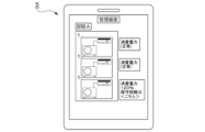
- FIG. 23 is a diagram showing a display example displayed on the general-purpose device 5 according to this embodiment.
- the information of the device the start date of operation, the device name, and the model of the compressor are displayed.
- the installation information of the device information about the installation location of the outdoor unit and the height at which the indoor unit is installed is displayed.
- Graphs of time-series data of the estimated refrigerant amount value and performance of the device 1 and the estimated refrigerant amount value and refrigerant management value are also displayed. These pieces of display information are information that assists work in failure or maintenance.
- the display example shown in this figure is only an example, and the present invention is not limited to this.
- the equipment management system SYS outputs information regarding failure or maintenance of the equipment 1 via the general-purpose device 5 based on the estimation result of the refrigerant amount or performance of the equipment 1 .
- the equipment management system SYS can confirm information that assists work in the failure or maintenance of the equipment 1 . Therefore, according to the present embodiment, it is possible to reduce the burden on the operator when the equipment 1 fails or perform maintenance, and to improve the efficiency of the work.
- the device management system SYS is not limited to cooling or heating, and similarly in the case of dehumidification or freezing, if the environment in which the device 1 is used exceeds the capacity of the device 1, may be dehumidified or refrigerated.
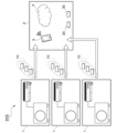
- FIG. 24 is a schematic configuration diagram showing an example of a device management system according to this embodiment.
- the equipment management system SYS consists of equipment 1 of a plurality of owners (owner A, owner B, owner C, . . . ) and equipment management apparatus 2 capable of communicating with each equipment 1.
- An owner is a person, an organization, or the like who owns the device 1 .
- This figure shows a plurality of devices 1 divided by owner in the configuration example of the device management system according to the second embodiment shown in FIG. It is the same in that it is communicably connected to the management device 2 .
- each owner has three devices 1
- the number may be one, two, or four or more.
- the number of owners is also not limited and may include owners in other countries as well as domestic owners.
- the general-purpose device 5 is an example of an external device, such as a device having a display screen (for example, a smartphone, a PC) or a device that emits sound (for example, a wireless earphone). is.
- the general-purpose device 5 is an external device used by each of owner A, owner B, owner C, etc., and is capable of communicating with the device management apparatus 2 .
- the reduction target for the total GWP of greenhouse gas (refrigerant) R410a is set by the Kyoto Protocol.
- the GWP total amount value is a value determined by "GWP (global warming potential) determined by refrigerant type" ⁇ "amount (weight) of refrigerant used".
- the amount (weight) of refrigerant used is, in other words, the amount (weight) of refrigerant charged in the device.
- F-gas (freon gas) regulations in Europe stipulate that the total amount of GWP will be reduced to 20% by 2030. Therefore, in equipment such as air conditioners that use a refrigerant, there is an increasing trend in various countries to reduce the amount of natural refrigerant with a low GWP and the amount of refrigerant used in the equipment.
- the reduction target for the total GWP value since the reduction target for the total GWP value is set, it is necessary to reduce the amount of refrigerant that can be filled in equipment year by year, or switch to a refrigerant with a lower GWP if the same refrigerant is used.
- the equipment sold in the past has remained in the market for 10 to 20 years, and it is essential to recover the refrigerant enclosed in the sold equipment as a social significance. In fact, the refrigerant recovery ratio is 38%, and most of it is released into the atmosphere, giving an adverse effect on global warming.
- the distribution volume of the refrigerant itself is a quota system (Quiota Allocation: distribution permission frame) in order to achieve the reduction target of the total GWP value. If the Quiota Allocation runs out, it cannot be sold. This results in a steep rise in the price of the refrigerant, which affects costs. Therefore, it is necessary to utilize a method of regenerating the refrigerant by reusing the refrigerant recovered from the equipment.
- the device management device 2 acquires the device acquisition data 10 from each of the plurality of devices 1, estimates the refrigerant amount in each of the plurality of devices 1, and Aggregate and manage data.
- FIG. 25 is a schematic block diagram showing an example of the configuration of the device management device 2 according to this embodiment.
- the device management apparatus 2 is the external terminal 3 or the cloud 4, as described above, and includes, for example, a storage unit 401, a communication unit 402, and a processing unit 403, similar to the example shown in FIG.
- the processing unit 403 includes an acquiring unit 404, an estimating unit 405, and an output unit 406 as a functional configuration for estimating the refrigerant amount and managing data by the CPU executing a control program stored in the storage unit 401. , and a data management unit 407 .
- the acquisition unit 404 acquires the device acquisition data 10 (see FIG. 8) from the plurality of devices 1 via the communication unit 402 and stores it in the storage unit 401 .
- the estimation unit 405 estimates each of the refrigerant amounts in the plurality of devices 1 . For example, the estimation unit 405 estimates the amount of refrigerant in the plurality of devices 1 based on the device acquisition data 10 acquired by the acquisition unit 404 and the device information 20 and device installation information 30 stored in the storage unit 401. 40 are calculated respectively.
- the output unit 406 visually or audibly outputs information based on data managed by the data management unit 407 , which will be described later, via the general-purpose device 5 .
- the data management unit 407 associates each of the refrigerant amounts in the plurality of devices 1 estimated by the estimation unit 405 with the refrigerant type and stores them in the storage unit 401 .
- the refrigerant type is the refrigerant type of the refrigerant used in each device 1 .
- the data management unit 407 refers to the device information 20 and identifies the refrigerant type of the refrigerant used in each device 1 .
- the data management unit 407 causes the storage unit 401 to store device refrigerant information such as information on the amount of refrigerant in a plurality of devices 1 estimated by the estimation unit 405 in association with the refrigerant type for each device 1 .
- the data management unit 407 determines the amount of refrigerant for each device 1 based on the amount of refrigerant for each device 1 and the regulation value for the upper limit of the amount of refrigerant that can be used in the space where each of the plurality of devices 1 is installed. It is determined whether or not it is within the regulation value, and determination information based on the determination result is stored in the storage unit 401 .
- the data management unit 407 determines whether or not the refrigerant for each device 1 is to be collected based on the refrigerant type for each device 1, and stores determination information based on the determination result in the storage unit 401. For example, if the type of refrigerant used in the device 1 is prohibited by regulations, the data management unit 407 determines that the refrigerant is to be collected.
- the data management unit 407 stores device refrigerant information associated with the refrigerant type for each device 1, the regulation value, determination information as to whether or not the amount of refrigerant for each device 1 is within the regulation value, and the collected refrigerant for each device 1. Determination information as to whether or not the device is a target is stored as device refrigerant data 410 in the storage unit 401 and managed.
- FIG. 26 is a diagram showing a data example of the device refrigerant data 410 according to this embodiment. Here, an example of data in the case where one device 1 is installed in one space (for example, room) is shown.
- the device refrigerant data 410 stores device refrigerant information, regulation values, determination information, etc. in association with each owner's device 1 .
- the device refrigerant information includes the refrigerant type, the GWP of the refrigerant type, and the refrigerant amount in the device.
- the intra-equipment refrigerant amount is the refrigerant amount (charged refrigerant amount) used for each apparatus 1 and is the value of the estimated refrigerant amount 40 estimated by the estimation unit 405 .
- the GWP total amount value is a value calculated by “GWP ⁇ equipment refrigerant amount”.
- the data management unit 407 may compare the internal refrigerant amount with the refrigerant amount regulation value for each device 1 and determine whether the internal refrigerant amount is within the refrigerant amount regulation value. For example, the data management unit 407 determines whether or not the refrigerant amount in the device is within the refrigerant amount regulation value, and if the device refrigerant amount exceeds the refrigerant amount regulation value, the regulation value is set. Determination information (“regulation”) indicating that the limit is exceeded may be stored in the device refrigerant data 410 .
- regulation Determination information
- the device refrigerant data 410 shown in this figure shows an example in which three devices 1 (two model ZW and one model EW) are installed in the room A.
- the total GWP regulation value is set for one space (here, room A). Therefore, the data management unit 407 calculates the “total GWP value for each space” by summing the “total GWP value for each device” of each of the three devices 1 installed in this room A, and calculates the “total GWP value for each space”. It is determined whether or not the GWP total amount value is within the GWP total amount regulation value.
- the total amount of refrigerant in each device 1 is obtained by dividing the total GWP value of room A by the GWP of the refrigerant type. It may be determined whether or not it is within the value (that is, the refrigerant amount regulation value for room A).
- FIG. 28 is a diagram showing a first example of display of information regarding the amount of refrigerant according to this embodiment.
- This figure shows an example in which information about the amount of refrigerant in the device 1 installed in the room A is displayed on the display screen of the general-purpose device 5 of the owner A.
- FIG. In this example, the type of refrigerant used in each of the three devices 1 installed in room A and the amount of refrigerant in the device (estimated amount of refrigerant 40) are displayed.
- the total refrigerant type and refrigerant amount used in the equipment 1 in room A, the regulation value for the size of room A (the legal regulation value for this refrigerant type), and the refrigerant amount used in room A (total amount of refrigerant) is within the regulation value.
- the total amount of refrigerant (total amount of refrigerant) is within the regulation value, for example, "The total amount of refrigerant is within the standard" is displayed as information indicating that it is within the regulation value.
- FIG. 29 is a diagram showing a second example of display of information regarding the amount of refrigerant according to the present embodiment. Similar to FIG. 28, this figure shows an example in which the display screen of owner A's general-purpose device 5 displays information about the amount of refrigerant in equipment 1 installed in room A. (total amount of refrigerant) exceeds the regulation value. When the total amount of refrigerant (total amount of refrigerant) exceeds the regulation value, information indicating that the regulation value is exceeded is displayed, for example, "Total amount of refrigerant exceeds.”
- FIG. 30 is a diagram showing a third example of display of information regarding the amount of refrigerant according to this embodiment. Similar to FIGS. 28 and 29, this figure shows an example in which information about the amount of refrigerant in the device 1 installed in the room A is displayed on the display screen of the general-purpose device 5 of the owner A. , shows a display example when there is a refrigerant to be collected.
- two of the three devices 1 installed in the room A use refrigerant R32, but one device uses refrigerant R22 whose use is prohibited. Therefore, as information indicating that there is a refrigerant to be collected, for example, "There is a refrigerant to be collected" is displayed.
- FIGS. 28 to 30 show display examples in which three devices 1 are installed in one space (for example, room A). is installed, information about the amount of refrigerant for one vehicle is displayed.
- the information regarding the refrigerant amount of the plurality of devices 1 is displayed in a list, and whether or not the refrigerant amount is within the regulation value is displayed.
- a determination result or a determination result as to whether or not there is a refrigerant to be collected may be displayed for each device 1 .
- the device management system SYS can easily grasp the amount of refrigerant in the plurality of devices 1 installed in the market. Further, the device management system SYS can easily grasp the refrigerant type of the refrigerant used in the plurality of devices 1 installed in the market.
- the device management system SYS can easily grasp whether or not the amount of refrigerant in each of the plurality of devices 1 installed in the market exceeds the regulation value.
- the device management device 2 calculates the total amount of refrigerant for each of the plurality of devices 1 installed in one space and one Based on the regulation value for the upper limit of the amount of refrigerant that can be used in the space, it is determined whether or not the total amount of refrigerant in one space is within the regulation value, and determination information based on the determination result is stored in the storage unit 401.
- the device management apparatus 2 determines whether or not the refrigerant for each device 1 is to be collected based on the refrigerant type for each device 1, and causes the storage unit 401 to store determination information based on the determination result.
- the device management system SYS can easily grasp whether or not the refrigerant type used in each of the plurality of devices 1 installed in the market is subject to recovery.
- the device management system SYS can easily notify users (owners, etc.) of refrigerant types and refrigerant amounts in a plurality of devices 1 installed in the market.
- the notified user may be the owner or the user (person in the space where the device 1 is installed).
- the management method in the device management system SYS is such that the device management device 2 obtains from a plurality of devices 1 having a refrigerant, the refrigerant temperature in the device 1, the electrical input (electrical characteristics) of the device 1, and a step of acquiring device acquisition data 10 (measurement information) indicating the measurement result of environmental information around the device 1; and a step of associating each of the estimated refrigerant amounts in the plurality of devices 1 with the refrigerant type and storing them in the storage unit 401 .
- the device management system SYS can easily grasp the amount of refrigerant in the plurality of devices 1 installed in the market. Further, the device management system SYS can easily grasp the refrigerant type of the refrigerant used in the plurality of devices 1 installed in the market.
- FIG. 31 is a schematic configuration diagram showing an example of a device management system according to this embodiment. This figure differs from the configuration shown in FIG. 24 in that the equipment management device 2 can communicate with the service terminal 6 and the refurbishing factory 7 .
- the service terminal 6 is a portable terminal possessed by a serviceman of a collection company that collects refrigerant from the market (for example, the device 1).
- the service terminal 6 may be a general-purpose device such as a smartphone or tablet PC, or may be a dedicated device.
- the service terminal 6 transmits to the device management apparatus 2 information about the refrigerant type and the amount of refrigerant input by the serviceman when the refrigerant is recovered.
- the estimation unit 405 estimates the estimated amount of refrigerant 40 in the plurality of devices 1 based on the device acquisition data 10 acquired by the acquisition unit 404 and the device information 20 and device installation information 30 stored in the storage unit 401. Calculate each.
- the data management unit 407 sums the amounts of refrigerant in the plurality of devices 1 estimated by the estimation unit 405 for each refrigerant type, and calculates the total amount of refrigerant in the device (hereinafter referred to as the “total amount in the device”). Each refrigerant type is associated and stored in the storage unit 401 . Further, the data management unit 407 associates the refrigerant amount of the recovered refrigerant and the refrigerant amount of the regenerated refrigerant acquired by the acquisition unit 404 with each refrigerant type and stores them in the storage unit 401 .
- the device management device 2 acquires information on the refrigerant type and the amount of refrigerant collected from one of the plurality of devices 1, and estimates a plurality of
- the storage unit 401 stores the total refrigerant amount in the device 1 and the collected refrigerant amount in association with each refrigerant type.
- the equipment management device 2 acquires, for each refrigerant type, information on the amount of regenerated refrigerant that has been regenerated and shipped from any one of the plurality of equipment 1, and obtains the amount of regenerated refrigerant that has been shipped. are stored in the storage unit 401 in association with each refrigerant type.
- the equipment management system SYS can easily grasp the percentage of the refrigerant recovered from the plurality of equipment 1 installed in the market that is being used as regenerated refrigerant. Therefore, the equipment management system SYS can easily grasp the response status of the environmental load to the market, and can appeal the environmental response to the market.
- the basic configuration of the equipment management system SYS according to this embodiment is the same as that of the fifth embodiment or the eighth embodiment.
- the user is notified by visual or auditory output.
- the external device is, for example, the general-purpose device 5 described above.
- the general-purpose device 5 visually or audibly outputs by displaying on the display screen of the general-purpose device 5 or outputting by sound.
- the equipment management system SYS estimates the amount of refrigerant in the equipment 1 and notifies the user of a decrease in the amount of refrigerant, deterioration in performance, lack of performance, etc., and promotes maintenance or replacement of the equipment 1.
- the equipment management system SYS is a model that is subject to environmental regulations based on the refrigerant type of the refrigerant in the equipment 1 (for example, a model that uses a refrigerant whose use is prohibited by regulation). In such a case, the user is notified, and maintenance or replacement of the device 1 is promoted.
- the device management device 2 estimates the amount of refrigerant in the device 1 periodically or at arbitrary timing, and retains data on the estimated amount of refrigerant in chronological order. A correlation formula between refrigerant quantity and performance is maintained, and performance is calculated from the estimated refrigerant quantity. In addition, when the estimated amount of refrigerant decreases from a certain time to a certain time, the device management device 2 predicts performance degradation of the device from the time difference ⁇ t.
- FIG. 33 is a diagram showing an example of changes in refrigerant amount and performance of the device 1 according to this embodiment. Similar to the example shown in FIG. 19, FIG. 33A is a diagram showing an example of the relationship between the amount of refrigerant and the performance of the device.
- the performance of the device 1 decreases from the optimum value (100% performance) to the current value (80% performance) as the amount of refrigerant decreases.
- the device management apparatus 2 predicts future performance deterioration, as shown in FIG. 33(B).
- the output unit 406 of the device management apparatus 2 transmits information regarding performance, maintenance or replacement (purchase of a new device), etc. to the general-purpose device 5 for the user of the device 1 based on this performance deterioration prediction. By transmitting, it is made to output from the general-purpose device 5 . That is, the output unit 406 provides the user of the device 1 with information based on the amount of refrigerant in the device 1 (information on performance, information on maintenance or replacement) so that the user can easily grasp the state of the device 1. It has a function as a notification part. As a result, the device management system SYS notifies the user of the device 1 of the state of the device 1 such as its performance, and when the performance is degraded, the device 1 is maintained or replaced (purchase of a new device). ) can be recommended.
- the output unit 406 may output from the general-purpose device 5 by transmitting information prompting the general-purpose device 5 to change from the refrigerant R410 with a GWP of 2090 to the refrigerant R32 with a GWP of 675.
- the total GWP amount value can be reduced to be within the total GWP regulation value.
- the output unit 406 may output from the general-purpose device 5 by transmitting information indicating that the refrigerant is to be collected to the general-purpose device 5 . Further, when the refrigerant in the equipment 1 is to be collected, information indicating that the refrigerant is to be collected may be sent to the general-purpose device 5, and information prompting replacement of the equipment may be sent to the general-purpose device 5 to output. .
- the general-purpose device 5 displays this information on the display screen of the general-purpose device 5.
- the general-purpose device 5 may output these pieces of information by voice.
- display examples of the general-purpose device 5 will be described with reference to FIGS.
- FIG. 34 is a diagram showing a first example of display on the general-purpose device 5 according to this embodiment.
- the model name CCC is a device that currently contains the recovery target refrigerant R22.”
- the model name CCC is a device that currently contains the recovery target refrigerant R22.”
- "If you want to replace your device ⁇ here>” is displayed as information prompting you to replace your device.
- a link is set to jump to a site that introduces a replacement model or to a replacement site.
- campaign information or the like to encourage replacement may be displayed, such as "You can purchase at a special price if you want to replace with our product.”
- the display screen of the general-purpose device 5 displays "model BBB is overcharged” as information about the model 1 overcharged with refrigerant among the other models 1 owned by the same owner. Power consumption may be increasing due to overcharging.” is displayed. Further, on the display screen of the general-purpose device 5, "request for maintenance ⁇ here>” is displayed as information prompting maintenance. A link to jump to the site of the maintenance request destination is set in " ⁇ here>".
- FIG. 35 is a diagram showing a second example of display of the general-purpose device according to this embodiment.
- the display screen of the general-purpose device 5 displays information indicating the type of refrigerant charged in each of the three devices 1 installed in the room A and the device to be recovered.
- this is a device for refrigerant recovery
- FIG. 37 is a diagram showing a fourth example of display of the general-purpose device according to this embodiment.
- the display screen of the general-purpose device 5 displays the capacity based on the refrigerant amount of each of the three devices 1 installed in the room A.
- FIG. Here, it is shown that the capacity of two of the three devices 1 is normal at 120%, and the capacity of one device is degraded at 80%.
- "request maintenance ⁇ here>” is displayed as information prompting maintenance in association with the device 1 whose capacity is 80%.
- a link to jump to the site of the maintenance request destination is set in " ⁇ here>".
- the display screen of the general-purpose device 5 also displays information indicating that the capacity of the room A as a whole is sufficient with the total capacity of the three devices 1 .
- the device management device 2 receives from the device 1 having a refrigerant the refrigerant temperature in the device 1, the electrical input (electrical characteristics) of the device 1, and the Device acquisition data 10 (measurement information) indicating measurement results of environmental information around the device 1 is acquired. Then, the device management apparatus 2 estimates the amount of refrigerant in the device 1 based on the acquired device acquisition data 10, the preset device information 20 related to the device 1, and the device installation information 30 related to the installation environment of the device 1. . In addition, the device management device 2 notifies the user (owner, user, etc.) of the device 1 of information based on the estimated amount of refrigerant in the device 1 .
- the device management system SYS estimates the amount of refrigerant in the device 1 and notifies the user of information based on the estimated amount of refrigerant, so that the user can easily grasp the state of the device 1.
- the equipment management device 2 estimates the performance of the equipment 1 based on preset equipment information 20 and equipment installation information 30, and the estimated amount of refrigerant in the equipment 1, and estimates the estimated performance of the equipment 1. to the user of the device 1.
- the device management device 2 notifies the user of the device 1 of information indicating that the refrigerant is a recovery target.
- the device management system SYS estimates the amount of refrigerant in the device 1 and notifies the user of information based on the estimated amount of refrigerant, so that the user can easily grasp the state of the device 1.
- the equipment management system SYS it is possible to create employment for maintenance workers involved in refrigerant recovery work and refrigerant charging work, and employment for development and sales associated with the replacement of the equipment 1.
- an example of an air conditioner capable of switching between cooling operation and heating operation has been described as an example of the device 1, but it may be a dedicated cooling device or a heating dedicated device.
- the refrigerant circuit is for cooling only, excluding the four-way valve 101 in FIG.
- the refrigerant circuit is for heating only, excluding the four-way valve 101 in FIG.
- part or all of the functions of the device management device 2 may be implemented as an integrated circuit such as an LSI (Large Scale Integration). Each function may be individually processorized, or part or all may be integrated and processorized. Also, the method of circuit integration is not limited to LSI, but may be realized by a dedicated circuit or a general-purpose processor. In addition, when an integration circuit technology that replaces LSI appears due to advances in semiconductor technology, an integrated circuit based on this technology may be used.
- LSI Large Scale Integration
Abstract
This device management system comprises: a device that has a refrigerant; an acquisition unit that acquires measurement information which indicates measurement results for environment information pertaining to the surroundings of the device, an electrical property of the device, and the refrigerant temperature in the device; an estimation unit which estimates the refrigerant amount inside the device on the basis of the measurement information acquired by the acquisition unit and of device installation information pertaining to the installation environment of the device and device information which pertains to a preset device; and a notification unit which notifies a user of the device of information based on the refrigerant amount in the device estimated by the estimation unit.
Description
本開示は、機器管理システムおよび通知方法に関する。
This disclosure relates to a device management system and a notification method.
対象空間の温度が所定の判定温度条件を満たすように温度調節を行って安定条件下にて冷媒温度を測定することにより、機器内の冷媒量を推定する空気調和機が開示されている(例えば、特許文献1参照)。
Disclosed is an air conditioner that estimates the amount of refrigerant in the device by adjusting the temperature so that the temperature of the target space satisfies a predetermined judgment temperature condition and measuring the refrigerant temperature under stable conditions (for example, , see Patent Document 1).
特許文献1に開示されている従来技術では、室外機及び室内機の空調負荷が一定でかつ、圧縮機周波数が一定となり冷凍サイクルが安定した場合には冷媒量を推定することが可能である。しかしながら、1日を通して外気温が一定でないこと、室内にいる人の人数、または室内にいる人の活動状態などによって室内機にかかる空調負荷が変化するため、空調負荷が一定となる環境は現実的にはない。よって、従来技術では、実使用環境における冷媒量の推定が困難であり、冷媒量を推定するためには特殊な運転が必要であった。このように、機器内の冷媒量を容易に把握する仕組みがなかったため、機器の状態を把握することが困難であった。
With the conventional technology disclosed in Patent Document 1, it is possible to estimate the amount of refrigerant when the air conditioning load of the outdoor unit and the indoor unit is constant, the compressor frequency is constant, and the refrigeration cycle is stable. However, since the air conditioning load on the indoor unit changes depending on factors such as the outside temperature being constant throughout the day, the number of people in the room, and the activity level of the people in the room, an environment where the air conditioning load is constant is realistic. not in Therefore, in the prior art, it is difficult to estimate the amount of refrigerant in an actual use environment, and a special operation is required to estimate the amount of refrigerant. As described above, since there was no mechanism for easily grasping the amount of refrigerant in the device, it was difficult to grasp the state of the device.
本開示は、上記した事情に鑑みてなされたものであり、機器の状態をユーザが容易に把握することができる機器管理システムおよび通知方法を提供することを目的の一つとする。
The present disclosure has been made in view of the circumstances described above, and aims to provide a device management system and a notification method that allow users to easily grasp the state of devices.
本開示に係る機器管理システムは、冷媒を有する機器と、前記機器内の冷媒温度、前記機器の電気的な特性、および前記機器の周囲の環境情報の測定結果を示す測定情報を取得する取得部と、前記取得部が取得した測定情報と、予め設定された前記機器に関する機器情報および前記機器の設置環境に関する機器設置情報とに基づいて、前記機器内の冷媒量を推定する推定部と、前記推定部により推定された前記機器内の冷媒量に基づく情報を、前記機器のユーザに対して通知する通知部と、
を備える。 A device management system according to the present disclosure includes a device having a refrigerant, an acquisition unit that acquires measurement information indicating the measurement results of the temperature of the refrigerant in the device, the electrical characteristics of the device, and the environmental information around the device. an estimating unit for estimating the amount of refrigerant in the device based on the measurement information acquired by the acquiring unit, preset device information regarding the device, and device installation information regarding the installation environment of the device; a notification unit that notifies a user of the device of information based on the amount of refrigerant in the device estimated by the estimation unit;
Prepare.
また、本開示に係る機器管理システムにおける通知方法は、取得部が、冷媒を有する機器内の冷媒温度、前記機器の電気的な特性、および前記機器の周囲の環境情報の測定結果を示す測定情報を取得するステップと、推定部が、前記取得部が取得した測定情報と、予め設定された前記機器に関する機器情報および前記機器の設置環境に関する機器設置情報とに基づいて、前記機器内の冷媒量を推定するステップと、通知部が、前記推定部により推定された前記機器内の冷媒量に基づく情報を、前記機器のユーザに対して通知するステップと、を含む。
Further, in the notification method in the device management system according to the present disclosure, the acquisition unit obtains measurement information indicating results of measurement of refrigerant temperature in a device having a refrigerant, electrical characteristics of the device, and environmental information around the device. and an estimating unit, based on the measurement information acquired by the acquiring unit, preset device information related to the device, and device installation information related to the installation environment of the device, the amount of refrigerant in the device and a notification unit notifying a user of the device of information based on the amount of refrigerant in the device estimated by the estimation unit.
本開示によれば、機器の状態をユーザが容易に把握することができる。
According to the present disclosure, the user can easily grasp the state of the device.
以下、図面を参照しながら実施形態について説明する。
<第1の実施形態>
まず、第1の実施形態について説明する。
[機器管理システムの概要]
図1は、本実施形態に係る機器管理システムの一例を示す概略構成図である。この図に示す機器管理システムSYSは、冷媒を有する機器1と、機器1と通信可能な機器管理装置2とを備えている。機器1は、例えば、室外機100と室内機200とを備える空気調和機である。機器管理装置2は、機器1からの通信データを保存するデータの管理先であるとともに、機器1内の冷媒量を推定する。ここでは、機器管理装置2として、外部端末3およびクラウド4を例示している。 Hereinafter, embodiments will be described with reference to the drawings.
<First embodiment>
First, the first embodiment will be described.
[Overview of equipment management system]
FIG. 1 is a schematic configuration diagram showing an example of a device management system according to this embodiment. The device management system SYS shown in this figure includes adevice 1 having a refrigerant and a device management device 2 capable of communicating with the device 1 . The device 1 is, for example, an air conditioner that includes an outdoor unit 100 and an indoor unit 200 . The device management device 2 is a data management destination that stores communication data from the device 1 and estimates the amount of refrigerant in the device 1 . Here, the external terminal 3 and the cloud 4 are exemplified as the device management device 2 .
<第1の実施形態>
まず、第1の実施形態について説明する。
[機器管理システムの概要]
図1は、本実施形態に係る機器管理システムの一例を示す概略構成図である。この図に示す機器管理システムSYSは、冷媒を有する機器1と、機器1と通信可能な機器管理装置2とを備えている。機器1は、例えば、室外機100と室内機200とを備える空気調和機である。機器管理装置2は、機器1からの通信データを保存するデータの管理先であるとともに、機器1内の冷媒量を推定する。ここでは、機器管理装置2として、外部端末3およびクラウド4を例示している。 Hereinafter, embodiments will be described with reference to the drawings.
<First embodiment>
First, the first embodiment will be described.
[Overview of equipment management system]
FIG. 1 is a schematic configuration diagram showing an example of a device management system according to this embodiment. The device management system SYS shown in this figure includes a
外部端末3は、スマートフォン、PC(Personal Computer)などの端末装置である。外部端末3は、機器1との通信の他、クラウド4と通信し、機器1からの通信データをクラウド4へ送信しても良い。クラウド4は、公衆回線等の通信ネットワークを介した演算処理装置群である。機器管理装置2は、外部端末3であっても良いし、クラウド4であっても良い。
The external terminal 3 is a terminal device such as a smartphone or a PC (Personal Computer). In addition to communicating with the device 1 , the external terminal 3 may communicate with the cloud 4 and transmit communication data from the device 1 to the cloud 4 . The cloud 4 is a group of arithmetic processing units connected via a communication network such as a public line. The device management device 2 may be the external terminal 3 or the cloud 4 .
機器管理システムSYSにおいては、機器1で取得される機器取得データ10と、機器1に関する機器情報20と、機器1が設置されている設置環境に関する機器設置情報30とに基づいて、機器1と通信接続される外部端末3またはクラウド4などの機器管理装置2が機器1内の冷媒量を推定する。
The device management system SYS communicates with the device 1 based on device acquisition data 10 acquired by the device 1, device information 20 regarding the device 1, and device installation information 30 regarding the installation environment in which the device 1 is installed. A connected external terminal 3 or a device management device 2 such as a cloud 4 estimates the amount of refrigerant in the device 1 .
例えば、機器取得データ10には、機器1内の冷媒温度の測定値(以下、「冷媒温度11」と称する)と、機器1内の電気的な特性の測定値(以下、「電気入力12」と称する)と、機器1の周囲の温度または湿度などの環境情報の測定値(以下、「環境情報13」と称する)などの測定情報とが含まれる。機器1は、機器取得データ10を機器管理装置2へ送信する。
For example, the device acquisition data 10 includes a measured value of the coolant temperature in the device 1 (hereinafter referred to as “refrigerant temperature 11”) and a measured value of the electrical characteristics in the device 1 (hereinafter referred to as “electrical input 12”). ) and measurement information such as a measured value of environmental information such as temperature or humidity around the device 1 (hereinafter referred to as “environmental information 13”). The device 1 transmits device acquisition data 10 to the device management apparatus 2 .
機器管理装置2、機器1から送信された機器取得データ10を取得する。また、機器管理装置2は、予め設定された機器情報20および機器設置情報30を有する。機器情報20には、出荷前の検査データが含まれる。例えば、機器情報20には、特定の検査条件下における機器1内の冷媒温度、機器1内の電気的な特性、または環境情報の検査データ(定常データまたは時系列データ)と、検査条件と、検査時点の機器1の仕様(構成)とが含まれる。機器設置情報30には、機器が設置されている場所の環境または設置状態などが含まれる。機器取得データ10、機器情報20、および機器設置情報30の詳細については後述する。
The device management device 2 acquires the device acquisition data 10 transmitted from the device 1. The device management apparatus 2 also has preset device information 20 and device installation information 30 . The device information 20 includes inspection data before shipment. For example, the device information 20 includes inspection data (stationary data or time-series data) of refrigerant temperature in the device 1 under specific inspection conditions, electrical characteristics in the device 1, or environmental information, inspection conditions, specifications (configuration) of the device 1 at the time of inspection. The device installation information 30 includes the environment or installation state of the place where the device is installed. Details of the device acquisition data 10, the device information 20, and the device installation information 30 will be described later.
[機器1の冷媒回路の構成]
図2は、本実施形態に係る機器の冷媒回路の一例を示す図である。室外機100と室内機200とは、内外接続配管301、302によって接続されている。内外接続配管301には、ガス(気体)状態の冷媒が通る。内外接続配管302には、液体状態の冷媒が通る。室外機100内に備えられた四方弁101を切り替えて冷媒の循環方向を切り替えることにより、暖房運転と冷房運転とが切り替わる。実線の矢印の向きが冷房運転時の冷媒の流れの向きを示しており、破線の矢印の向きが暖房運転時の冷媒の流れの向きを示している。 [Configuration of refrigerant circuit of device 1]
FIG. 2 is a diagram showing an example of a refrigerant circuit of equipment according to the present embodiment. Theoutdoor unit 100 and the indoor unit 200 are connected by inside/ outside connection pipes 301 and 302 . A refrigerant in a gaseous state passes through the internal/external connection pipe 301 . A coolant in a liquid state passes through the internal/external connection pipe 302 . By switching the four-way valve 101 provided in the outdoor unit 100 to switch the circulation direction of the refrigerant, the heating operation and the cooling operation are switched. The direction of the solid line arrow indicates the direction of refrigerant flow during cooling operation, and the direction of the broken line arrow indicates the direction of refrigerant flow during heating operation.
図2は、本実施形態に係る機器の冷媒回路の一例を示す図である。室外機100と室内機200とは、内外接続配管301、302によって接続されている。内外接続配管301には、ガス(気体)状態の冷媒が通る。内外接続配管302には、液体状態の冷媒が通る。室外機100内に備えられた四方弁101を切り替えて冷媒の循環方向を切り替えることにより、暖房運転と冷房運転とが切り替わる。実線の矢印の向きが冷房運転時の冷媒の流れの向きを示しており、破線の矢印の向きが暖房運転時の冷媒の流れの向きを示している。 [Configuration of refrigerant circuit of device 1]
FIG. 2 is a diagram showing an example of a refrigerant circuit of equipment according to the present embodiment. The
暖房運転の場合、室外機100の圧縮機102により圧縮されたガス(気体)状態の冷媒が、四方弁101および内外接続配管301を通って室内機200の室内熱交換器201に流れる。室内熱交換器201内の冷媒は周囲の空気と熱交換して周囲の空気を暖める。熱交換によって液体状態となった冷媒は、内外接続配管302を通って室外機100の膨張弁103に流れ、膨張弁103を通って室外熱交換器104に流入する。室外熱交換器104内の冷媒は周囲の空気と熱交換する。熱交換によってガス(気体)状態となった冷媒が四方弁101を通って圧縮機102に戻る。
In the case of heating operation, gaseous refrigerant compressed by the compressor 102 of the outdoor unit 100 flows through the four-way valve 101 and the internal/external connection pipe 301 to the indoor heat exchanger 201 of the indoor unit 200 . The refrigerant in the indoor heat exchanger 201 exchanges heat with the ambient air to warm the ambient air. The refrigerant that has become liquid due to heat exchange flows through the internal/external connection pipe 302 to the expansion valve 103 of the outdoor unit 100 , and flows through the expansion valve 103 into the outdoor heat exchanger 104 . The refrigerant in the outdoor heat exchanger 104 exchanges heat with the surrounding air. Refrigerant in a gaseous state through heat exchange passes through the four-way valve 101 and returns to the compressor 102 .
冷房運転の場合、室外機100の圧縮機102により圧縮されたガス(気体)状態の冷媒が、四方弁101を通って室外熱交換器104に流入する。室外熱交換器104内の冷媒は周囲の空気と熱交換する。熱交換により液体状態となった冷媒は膨張弁103および内外接続配管302を通って室内機200の室内熱交換器201に流入する。室内熱交換器201内の冷媒は周囲の空気と熱交換して周囲の空気を冷やす。熱交換によりガス(気体)状態となった冷媒は、内外接続配管301および四方弁101を通って室外機100の圧縮機102に戻る。
In the case of cooling operation, gaseous refrigerant compressed by the compressor 102 of the outdoor unit 100 flows through the four-way valve 101 into the outdoor heat exchanger 104 . The refrigerant in the outdoor heat exchanger 104 exchanges heat with the surrounding air. The refrigerant that has become liquid due to heat exchange flows through the expansion valve 103 and the internal/external connecting pipe 302 into the indoor heat exchanger 201 of the indoor unit 200 . The refrigerant in the indoor heat exchanger 201 exchanges heat with the surrounding air to cool the surrounding air. The refrigerant that has become gaseous due to heat exchange returns to the compressor 102 of the outdoor unit 100 through the internal/external connection pipe 301 and the four-way valve 101 .
室外機100及び室内機200には、冷媒温度を測定するための温度センサが各部に設けられている。図3は、図2に示す温度の測定点T1~T8の測定箇所の説明図である。圧縮機102の出口側と入口側のそれぞれに温度センサが設けられており、出口側の測定点T1が吐出温度、入り口側の測定点T8が吸入温度の測定点である。
A temperature sensor for measuring the refrigerant temperature is provided in each part of the outdoor unit 100 and the indoor unit 200 . FIG. 3 is an explanatory diagram of the temperature measurement points T1 to T8 shown in FIG. A temperature sensor is provided on each of the outlet side and the inlet side of the compressor 102, the outlet side measuring point T1 is the outlet side measuring point, and the inlet side measuring point T8 is the suction temperature measuring point.
また、室外機100の膨張弁103および室外熱交換器104と、室内機200の室内熱交換器201とのそれぞれには、出口側、入り口側、および出口と入口の間の中間の3か所に温度センサが設けられている。室外熱交換器104は、冷房運転時には凝縮器として機能する。測定点T2、T2-3、T3のそれぞれは、冷房運転時の凝縮器の入口温度、中間温度、出口温度の測定点となる。一方、室外熱交換器104は、暖房運転時には蒸発器として機能する。測定点T2、T2-3、T3のそれぞれは、暖房運転時の蒸発器の出口温度、中間温度、入口温度の測定点となる。
Further, the expansion valve 103 and the outdoor heat exchanger 104 of the outdoor unit 100 and the indoor heat exchanger 201 of the indoor unit 200 are each provided with three points: the outlet side, the inlet side, and the middle point between the outlet and the inlet. is provided with a temperature sensor. The outdoor heat exchanger 104 functions as a condenser during cooling operation. Measurement points T2, T2-3, and T3 are measurement points for the inlet temperature, intermediate temperature, and outlet temperature of the condenser during cooling operation, respectively. On the other hand, the outdoor heat exchanger 104 functions as an evaporator during heating operation. Measurement points T2, T2-3, and T3 are measurement points for the outlet temperature, intermediate temperature, and inlet temperature of the evaporator during heating operation, respectively.
室内熱交換器201は、冷房運転時には蒸発器として機能する。測定点T6、T6-7、T7のそれぞれは、冷房運転時の蒸発器の入口温度、中間温度、出口温度の測定点となる。一方、室内熱交換器201は、暖房運転時には凝縮器として機能する。測定点T6、T6-7、T7のそれぞれは、暖房運転時の凝縮器の出口温度、中間温度、入口温度の測定点となる。
The indoor heat exchanger 201 functions as an evaporator during cooling operation. Measurement points T6, T6-7, and T7 are measurement points for the inlet temperature, intermediate temperature, and outlet temperature of the evaporator during cooling operation, respectively. On the other hand, indoor heat exchanger 201 functions as a condenser during heating operation. Measurement points T6, T6-7, and T7 are measurement points for the outlet temperature, intermediate temperature, and inlet temperature of the condenser during heating operation, respectively.
また、測定点T4は、冷房運転時には膨張弁103の入口温度、暖房運転時には膨張弁103の出口温度の測定点となる。測定点T5は、冷房運転時には膨張弁103の出口温度、暖房運転時には膨張弁103の入口温度の測定点となる。
Also, the measurement point T4 serves as a measurement point for the inlet temperature of the expansion valve 103 during cooling operation, and for the outlet temperature of the expansion valve 103 during heating operation. The measurement point T5 serves as a measurement point for the outlet temperature of the expansion valve 103 during cooling operation and for the inlet temperature of the expansion valve 103 during heating operation.
なお、機器1は、1台の室外機100に複数の室内機200が接続されるマルチ型空気調和機(所謂、パッケージエアコン)であってもよい。
Note that the device 1 may be a multi-type air conditioner (a so-called package air conditioner) in which a plurality of indoor units 200 are connected to one outdoor unit 100.
図4は、マルチ型空気調和機の冷媒回路の一例を示す図である。この図4では、室外機100に2台の室内機200が接続されている場合の冷媒回路の例を示している。この図4において、図2の各部に対応する構成には同一の符号を付している。図示する冷媒回路の構成は、室内機200の数が異なる点を除いて、図2に示す冷媒回路の例と同様である。なお、室内機200の数は、2台に限られるものではない。
FIG. 4 is a diagram showing an example of a refrigerant circuit of a multi-type air conditioner. FIG. 4 shows an example of a refrigerant circuit when two indoor units 200 are connected to the outdoor unit 100. As shown in FIG. In FIG. 4, the same reference numerals are assigned to the components corresponding to those in FIG. The configuration of the illustrated refrigerant circuit is the same as the example of the refrigerant circuit illustrated in FIG. 2 except that the number of indoor units 200 is different. Note that the number of indoor units 200 is not limited to two.
マルチ型空気調和機は、室内機200が複数であるため、例えば、室内機200に対して1号機、2号機、・・・といったように号機の設定がされる。そして、「1号機の吐出温度、凝縮器の入口温度、・・・」、「2号機の吐出温度、凝縮器の入口温度、・・・」といったように号機を付与し、号機ごとに冷媒温度が区別されて取り扱われる。
Since the multi-type air conditioner has a plurality of indoor units 200, for example, the indoor units 200 are set to No. 1, No. 2, and so on. Then, assign the unit number such as "discharge temperature of unit 1, inlet temperature of condenser, ...", "discharge temperature of unit 2, inlet temperature of condenser, ...", and the refrigerant temperature for each unit are treated separately.
なお、本実施形態では、室内機200が1台であっても複数であっても、機器1の数は、基本的に1台の室外機100に対して1台とする。
Note that in this embodiment, the number of devices 1 is basically one for one outdoor unit 100 regardless of whether there is one indoor unit 200 or a plurality of indoor units 200 .
図5及び図6に冷房運転時のモリエル線図の一例を模式的に示す。図5は、起動直後(運転初期)のモリエル線図の一例を示す図である。図6は、安定時のモリエル線図の一例を示す図である。一般に、運転初期は、測定点T1~T8においてすべて気液二相域(二相域)内にある(図5参照)。その後、徐々に、圧縮機102によって冷媒ガスが圧縮されることにより、凝縮器と蒸発器間の圧力差が拡大し、吐出温度の測定点T1ではガス化し気相域内に遷移する(図6参照)。また、凝縮器の出口温度の測定点T3では凝縮器による空気との熱交換によって、エンタルピーが減少する。冷媒ガス量と凝縮器の熱交換量が十分であれば、測定点T3では液相域内に遷移する(図6参照)。一方で、冷媒ガス量が十分でない場合は、凝縮器および蒸発器における熱交換が不十分となる。
Figures 5 and 6 schematically show an example of a Mollier diagram during cooling operation. FIG. 5 is a diagram showing an example of a Mollier diagram immediately after startup (in the initial stage of operation). FIG. 6 is a diagram showing an example of a Mollier diagram at the time of stability. Generally, at the initial stage of operation, all measurement points T1 to T8 are within the gas-liquid two-phase region (two-phase region) (see FIG. 5). After that, as the refrigerant gas is gradually compressed by the compressor 102, the pressure difference between the condenser and the evaporator increases, and at the discharge temperature measurement point T1, it is gasified and transitions into the gas phase region (see FIG. 6). ). Also, at the measurement point T3 of the outlet temperature of the condenser, the enthalpy decreases due to heat exchange with the air by the condenser. If the amount of refrigerant gas and the amount of heat exchange in the condenser are sufficient, the measurement point T3 transitions into the liquid phase region (see FIG. 6). On the other hand, if the amount of refrigerant gas is insufficient, heat exchange in the condenser and evaporator will be insufficient.
[機器1の電気回路の構成]
次に、図7を参照して、機器1の主要な電気回路の一例について説明する。
図7は、本実施形態に係る機器1の電気回路の一例を示す図である。この図7において、図2の各部に対応する構成には同一の符号を付している。 [Configuration of electric circuit of device 1]
Next, an example of main electrical circuits of thedevice 1 will be described with reference to FIG.
FIG. 7 is a diagram showing an example of an electric circuit of thedevice 1 according to this embodiment. In FIG. 7, the same reference numerals are given to the components corresponding to the parts in FIG.
次に、図7を参照して、機器1の主要な電気回路の一例について説明する。
図7は、本実施形態に係る機器1の電気回路の一例を示す図である。この図7において、図2の各部に対応する構成には同一の符号を付している。 [Configuration of electric circuit of device 1]
Next, an example of main electrical circuits of the
FIG. 7 is a diagram showing an example of an electric circuit of the
室外機100は、室外機制御部110を備えている。室外機制御部110は、マイクロコンピュータを含んで構成されており、室外機100の各部の制御、および室外機100に設けられている各種センサの測定値を取得する。例えば、室外機制御部110は、図2及び図3で説明した冷媒温度の測定点T1、T2、T2-3、T3、T4、T5、T8のそれぞれに設けられた温度センサの測定値を取得する。
The outdoor unit 100 includes an outdoor unit control section 110. The outdoor unit control unit 110 includes a microcomputer, controls each unit of the outdoor unit 100 and obtains measurement values of various sensors provided in the outdoor unit 100 . For example, the outdoor unit control unit 110 acquires the measured values of the temperature sensors provided at the refrigerant temperature measurement points T1, T2, T2-3, T3, T4, T5, and T8 described in FIGS. do.
また、室外機制御部110は、四方弁101における冷媒の流れ方向の切り替え制御、圧縮機102の制御、膨張弁103の開度の制御、室外熱交換器104に対して送風する室外ファン105の回転制御などを行う。
In addition, the outdoor unit control unit 110 controls switching of the refrigerant flow direction in the four-way valve 101, controls the compressor 102, controls the opening degree of the expansion valve 103, and controls the outdoor fan 105 that blows air to the outdoor heat exchanger 104. Rotation control, etc.
圧縮機102は、圧縮部102aと、圧縮機モータ102bとを備えている。圧縮部102aは、ロータリ式またはスクロール式などの圧縮機構を有し、入口側から吸入された冷媒を圧縮して出口側から吐出する。圧縮機モータ102bは、インバータ120による回転制御が可能な三相モータを備え、圧縮部102aの圧縮機構を駆動する。室外機制御部110は、インバータ120を制御することにより、圧縮機モータ102bの回転を制御して圧縮部102aの圧縮機構を制御する。
The compressor 102 includes a compression section 102a and a compressor motor 102b. Compression part 102a has a compression mechanism such as a rotary type or a scroll type, compresses the refrigerant sucked from the inlet side, and discharges it from the outlet side. Compressor motor 102b includes a three-phase motor whose rotation can be controlled by inverter 120, and drives the compression mechanism of compression section 102a. By controlling the inverter 120, the outdoor unit control section 110 controls the rotation of the compressor motor 102b to control the compression mechanism of the compression section 102a.
室内機200は、室内機制御部210を備えている。室内機制御部210は、マイクロコンピュータを含んで構成されており、室内機200の各部の制御、および室内機200に設けられている各種センサの測定値を取得する。例えば、室内機制御部210は、図2及び図3で説明した冷媒温度の測定点T6、T6-7、T7のそれぞれに設けられた温度センサの測定値を取得する。また、室内機制御部210は、室内熱交換器201に対して送風する室内ファン202の回転制御などを行う。
The indoor unit 200 includes an indoor unit control section 210. The indoor unit control unit 210 includes a microcomputer, controls each unit of the indoor unit 200, and acquires measurement values of various sensors provided in the indoor unit 200. For example, the indoor unit control unit 210 acquires the measured values of the temperature sensors provided at the refrigerant temperature measurement points T6, T6-7, and T7 described with reference to FIGS. 2 and 3, respectively. The indoor unit control unit 210 also controls the rotation of the indoor fan 202 that blows air to the indoor heat exchanger 201, and the like.
また、室内機200は、無線機器220を備えている。無線機器220は、例えば、室内機200にオプションとして追加される機器付随デバイスの一つである。無線機器220は、無線通信により無線LAN(Local Area Network)またはインターネットなどの通信ネットワークに接続し、機器管理装置2(外部端末3またはクラウド4)とデータ通信を行う。
In addition, the indoor unit 200 includes a wireless device 220. The wireless device 220 is, for example, one of device-associated devices added to the indoor unit 200 as an option. The wireless device 220 connects to a communication network such as a wireless LAN (Local Area Network) or the Internet by wireless communication, and performs data communication with the device management device 2 (the external terminal 3 or the cloud 4).
室内機制御部210は、室外機制御部110と内外通信線310で接続されている。室内機制御部210は、内外通信線310を介して室外機制御部110から取得したデータと、室内機制御部210自身が取得したデータとに基づいて機器取得データ10を生成する。そして、室内機制御部210は、無線機器220を介して機器管理装置2(外部端末3またはクラウド4)へ機器取得データ10を送信する。
The indoor unit control section 210 is connected to the outdoor unit control section 110 via an internal/external communication line 310 . The indoor unit controller 210 generates device acquisition data 10 based on data acquired from the outdoor unit controller 110 via the indoor/outdoor communication line 310 and data acquired by the indoor unit controller 210 itself. Then, the indoor unit control section 210 transmits the device acquisition data 10 to the device management device 2 (the external terminal 3 or the cloud 4) via the wireless device 220. FIG.
ここで、従来の空気調和機では、圧縮機の周波数を固定し、なおかつ、冷凍サイクルが安定しているときの各種冷媒温度または圧力を空気調和機より取得する必要がある。これは、冷媒量を推定する際に、液相域および冷媒の気液二相域の質量を正確に推定するため、冷凍サイクルの特性上、凝縮器の気液二相域における圧力と、凝縮器の出口側のサブクール域を把握する必要があるためである。
Here, in conventional air conditioners, it is necessary to fix the frequency of the compressor and acquire various refrigerant temperatures or pressures from the air conditioner when the refrigeration cycle is stable. When estimating the amount of refrigerant, the mass of the liquid phase region and the gas-liquid two-phase region of the refrigerant are accurately estimated. This is because it is necessary to grasp the subcooled region on the outlet side of the vessel.
すなわち、従来の空気調和機は、室外機および室内機の空調負荷が一定でかつ、圧縮機周波数が一定となり冷凍サイクルが安定した状態では、冷媒量を推定することが可能であった。
In other words, with conventional air conditioners, it was possible to estimate the amount of refrigerant when the air conditioning load of the outdoor and indoor units was constant, the compressor frequency was constant, and the refrigeration cycle was stable.
しかしながら、空気調和機は、試験室のように室外機および室内機の空調負荷が一定となる環境は、現実的にはない。例えば、室外機に着目した場合、1日を通して外気温が一定でないことによって、室外機にかかる空調負荷が変化する。また、室内機に着目した場合、室内にいる人の人数、またはその人の活動状態によって、室内機にかかる空調負荷が変化する。
However, for air conditioners, there is no realistic environment where the air conditioning load of the outdoor and indoor units is constant like in a test room. For example, when focusing on the outdoor unit, the air conditioning load applied to the outdoor unit changes due to the outside temperature not being constant throughout the day. Further, when focusing on the indoor unit, the air conditioning load applied to the indoor unit changes depending on the number of people in the room or their activity status.
したがって、一般に、室内の温度一定(または湿度一定)とするように、空気調和機の圧縮機を制御する場合、圧縮機周波数が可変に遷移する動作となるため、実使用環境を考慮した場合、冷媒量を推定することは困難であった。そのため、冷媒量を推定するためには特殊な運転が必要であった。
Therefore, in general, when controlling the compressor of an air conditioner so as to maintain a constant indoor temperature (or constant humidity), the compressor frequency is variably changed. It was difficult to estimate the amount of refrigerant. Therefore, a special operation was required to estimate the amount of refrigerant.
また、従来技術において、冷媒量を推定するためには、実験または数値シミュレーション等によって、パラメータを定義する必要があるが、機器の仕様の数に応じて、全数評価する必要がある。そのため、開発コストが増加してしまう課題もある。一方で、機器の仕様を汎用的に共通のモデルとなるように定義した場合、冷媒量の推定精度が低下してしまうという課題もあった。
In addition, in the conventional technology, in order to estimate the amount of refrigerant, it is necessary to define parameters by experiments or numerical simulations, etc., but it is necessary to evaluate all of them according to the number of equipment specifications. Therefore, there is also a problem that the development cost increases. On the other hand, there is also the problem that the accuracy of estimating the amount of refrigerant deteriorates when the equipment specifications are defined to be a general-purpose, common model.
そこで、図1を参照して説明したように、本実施形態では、機器取得データ10と、機器情報20と機器設置情報30とに基づいて、機器1と通信接続される機器管理装置2(外部端末3またはクラウド4)が機器1内の冷媒量を推定する。これにより、機器管理システムSYSは、特殊な運転を必要とせず実使用環境において精度よく機器1内の冷媒量を推定することができる。以下、詳細に説明する。
Therefore, as described with reference to FIG. 1, in this embodiment, based on the device acquisition data 10, the device information 20, and the device installation information 30, the device management device 2 (external The terminal 3 or the cloud 4) estimates the amount of refrigerant in the device 1. As a result, the equipment management system SYS can accurately estimate the amount of refrigerant in the equipment 1 in the actual use environment without requiring any special operation. A detailed description will be given below.
[機器取得データの具体例]
まず、機器取得データ10に含まれるデータ項目の具体例について説明する。
図8は、本実施形態に係る機器取得データ10のデータ項目の一例を示す図である。前述したように、機器取得データ10には、冷媒温度11と電気入力12と環境情報13とが含まれる。 [Specific example of device acquisition data]
First, specific examples of data items included in thedevice acquisition data 10 will be described.
FIG. 8 is a diagram showing an example of data items of thedevice acquisition data 10 according to this embodiment. As described above, the device acquisition data 10 includes coolant temperature 11, electrical input 12, and environment information 13. FIG.
まず、機器取得データ10に含まれるデータ項目の具体例について説明する。
図8は、本実施形態に係る機器取得データ10のデータ項目の一例を示す図である。前述したように、機器取得データ10には、冷媒温度11と電気入力12と環境情報13とが含まれる。 [Specific example of device acquisition data]
First, specific examples of data items included in the
FIG. 8 is a diagram showing an example of data items of the
冷媒温度11には、例えば、吐出温度、凝縮器および蒸発器の入口から出口までの任意の箇所の温度(例えば、入口温度、中間温度、出口温度)、膨張弁103の温度(例えば、入口温度、出口温度)、吸入温度等が含まれる。なお、冷媒温度11には、上記の全ての箇所の温度が含まれてもよいし、一部が含まれてもよい。冷媒温度11に、上記の一部が含まれる場合、少なくとも吐出温度が含まれることが好ましい。また、冷媒温度11に、凝縮器および蒸発器の入口温度、中間温度、および出口温度の全てが含まれない場合には、少なくとも中間温度が含まれることが好ましい。
The refrigerant temperature 11 includes, for example, the discharge temperature, the temperature at any point from the inlet to the outlet of the condenser and evaporator (eg, inlet temperature, intermediate temperature, outlet temperature), the temperature of the expansion valve 103 (eg, inlet temperature , outlet temperature), inlet temperature, etc. In addition, the coolant temperature 11 may include the temperatures of all the locations described above, or may include some of them. When the refrigerant temperature 11 includes part of the above, it preferably includes at least the discharge temperature. Also, if the refrigerant temperature 11 does not include all of the inlet temperature, intermediate temperature, and outlet temperature of the condenser and evaporator, it preferably includes at least the intermediate temperature.
なお、内外接続配管301、302にも温度センサを設け、内外接続配管301の温度(例えば、入口温度、出口温度)が冷媒温度11に含まれてもよい。また、冷媒温度11には、上記の箇所の温度に限らず、機器1が取得可能な任意の箇所の冷媒温度が含まれてもよい。より多くの箇所の冷媒温度の測定値が冷媒温度11に含まれるほど、冷媒量の推定精度がより高くなる。
Temperature sensors may also be provided in the internal/ external connection pipes 301 and 302, and the temperature of the internal/external connection pipe 301 (for example, inlet temperature and outlet temperature) may be included in the coolant temperature 11. In addition, the coolant temperature 11 is not limited to the temperature at the location described above, and may include the coolant temperature at any location that can be acquired by the device 1 . The refrigerant temperature 11 includes measured values of the refrigerant temperature at more points, the higher the refrigerant amount estimation accuracy.
電気入力12には、例えば、室外ファン105および室内ファン202の電圧(母線電圧、線間電圧、相電圧)、電流(母線電流、線間電流、相電流)、回転数(現在回転数、司令回転数)、消費電力等が含まれる。また、電気入力12には、例えば、圧縮機102の電圧(母線電圧、線間電圧、相電圧)、電流(母線電流、線間電流、相電流)、周波数(現在周波数、司令周波数)、消費電力等が含まれる。また、電気入力12には、例えば、膨張弁103の開度(現在開度、司令開度)、消費電力等が含まれる。また、電気入力12には、例えば、電源側の電圧(一次電圧)および電流(一次電流)、機器付随デバイス(例えば、無線機器220、ヒータ、空気清浄デバイスなど)の消費電力が含まれる。
The electrical input 12 includes, for example, voltages (bus voltage, line voltage, phase voltage), currents (bus current, line current, phase current), rotation speeds (current rotation speed, command speed), power consumption, etc. Also, the electrical input 12 includes, for example, voltage (bus voltage, line voltage, phase voltage), current (bus current, line current, phase current), frequency (current frequency, command frequency), consumption of the compressor 102, Electricity, etc. are included. Further, the electrical input 12 includes, for example, the degree of opening of the expansion valve 103 (current degree of opening, commanded degree of opening), power consumption, and the like. The electrical input 12 also includes, for example, the voltage (primary voltage) and current (primary current) on the power supply side, and the power consumption of device-attached devices (eg, wireless device 220, heaters, air cleaning devices, etc.).
なお、機器付随デバイスの消費電力は、室外ファン105、室内ファン202、または圧縮機102における電圧、電流、または電力を直接的に取得できない場合に、当該取得できない電圧、電流、または電力を機器1の全体の総和から間接法にて推定するために用いられる。
If the voltage, current, or power of the outdoor fan 105, the indoor fan 202, or the compressor 102 cannot be directly obtained, the power consumption of the device-attached device is determined by the voltage, current, or power that cannot be obtained by the device 1. It is used to estimate by the indirect method from the total sum of
なお、電気入力12には、上記の全てのデータ項目が含まれてもよいし、一部が含まれてもよい。例えば、電気入力12には、少なくとも、室外ファン105および室内ファン202の回転数(現在回転数)と、圧縮機102の母線電流および現在周波数と、膨張弁103の現在開度と含まれることが好ましい。
It should be noted that the electrical input 12 may include all of the above data items, or may include some of them. For example, the electrical input 12 may include at least the number of revolutions (current number of revolutions) of the outdoor fan 105 and the indoor fan 202, the bus current and current frequency of the compressor 102, and the current opening of the expansion valve 103. preferable.
なお、電気入力12には、上記のデータ項目の他、機器1が取得可能な機器1内の任意の電気的な特性が含まれてもよい。より多くのデータ項目が電気入力12に含まれるほど、冷媒量の推定精度がより高くなる。
In addition to the data items described above, the electrical input 12 may include arbitrary electrical characteristics within the device 1 that can be acquired by the device 1 . The more data items included in the electrical input 12, the more accurate the refrigerant quantity estimate.
環境情報13には、例えば、室外機100および室内機200が取得する周囲の温度(室外温度、室内温度)と湿度(室外湿度、室内湿度)とが含まれる。なお、環境情報13には、上記の全てのデータ項目が含まれてもよいし、一部が含まれてもよい。例えば、環境情報13には、少なくとも室内温度が含まれることが好ましい。
The environmental information 13 includes, for example, ambient temperature (outdoor temperature, indoor temperature) and humidity (outdoor humidity, indoor humidity) acquired by the outdoor unit 100 and the indoor unit 200 . The environment information 13 may include all of the above data items, or may include some of them. For example, the environment information 13 preferably includes at least room temperature.
なお、環境情報13には、上記のデータ項目の他、機器1が取得可能な環境情報が含まれてもよい。より多くのデータ項目が環境情報13に含まれるほど、冷媒量の推定精度がより高くなる。
In addition to the above data items, the environment information 13 may include environment information that the device 1 can acquire. The more data items are included in the environmental information 13, the higher the refrigerant amount estimation accuracy.
機器1は、図8を参照して説明した機器取得データ10を、機器管理装置2へ送信する。図9は、機器1が送信する機器取得データ10の一例を示す図である。例えば、機器1は、図9に示すように、一定の時間間隔で測定した機器取得データ10の時系列データを送信する。なお、機器1は、機器取得データ10の送信の際に、ある条件下における定点のデータを送信してもよい。
The device 1 transmits the device acquisition data 10 described with reference to FIG. FIG. 9 is a diagram showing an example of device acquisition data 10 transmitted by the device 1. As shown in FIG. For example, as shown in FIG. 9, the device 1 transmits time-series data of device acquired data 10 measured at regular time intervals. Note that the device 1 may transmit fixed point data under certain conditions when transmitting the device acquired data 10 .
[機器情報の具体例]
次に、機器情報20に含まれるデータ項目の具体例について説明する。
図10は、本実施形態に係る機器情報20のデータ項目の一例を示す図である。前述したように、機器情報20には、出荷前の検査データと、検査条件と、検査時点の機器1の仕様(構成)とが含まれる。 [Specific example of device information]
Next, specific examples of data items included in thedevice information 20 will be described.
FIG. 10 is a diagram showing an example of data items of thedevice information 20 according to this embodiment. As described above, the device information 20 includes pre-shipment inspection data, inspection conditions, and specifications (configuration) of the device 1 at the time of inspection.
次に、機器情報20に含まれるデータ項目の具体例について説明する。
図10は、本実施形態に係る機器情報20のデータ項目の一例を示す図である。前述したように、機器情報20には、出荷前の検査データと、検査条件と、検査時点の機器1の仕様(構成)とが含まれる。 [Specific example of device information]
Next, specific examples of data items included in the
FIG. 10 is a diagram showing an example of data items of the
この図10において、共通項目には、検査時点の機器1の仕様(構成)などが含まれる。例えば、共通項目には、検査日時(No.1)、検査に使用した試験室(No.2)、検査した機器1の製造情報および製品仕様などが含まれる。製造情報には、ロット番号(No.3)、製造年度(No.6)などが含まれる。製品仕様には、機器1の機種(No.4)、能力(No.5)の他、電源仕様、冷媒種と封入量、冷凍機油の種類と油量、圧縮機102の型式、ストロークボリューム、圧縮機モータ102bの仕様、圧縮機102の内容積、室外熱交換器104の内容積、室内熱交換器201の内容積、レシーバの内容積(No.7~No.18)などが含まれる。
In FIG. 10, the common items include the specifications (configuration) of the device 1 at the time of inspection. For example, common items include date and time of inspection (No. 1), test room used for inspection (No. 2), manufacturing information and product specifications of the inspected device 1, and the like. The manufacturing information includes lot number (No. 3), manufacturing year (No. 6), and the like. In addition to the model (No. 4) and capacity (No. 5) of the device 1, the product specifications include power supply specifications, refrigerant type and amount, type and amount of refrigerating machine oil, type of compressor 102, stroke volume, The specifications of the compressor motor 102b, the internal volume of the compressor 102, the internal volume of the outdoor heat exchanger 104, the internal volume of the indoor heat exchanger 201, the internal volume of the receiver (No. 7 to No. 18), etc. are included.
なお、レシーバは、例えば室外機100の膨張弁103と内外接続配管302との接続部分の近傍に設けられている。このレシーバは、冷房運転と暖房運転とで必要冷媒量に差異が出るため、余剰冷媒を貯めるために設けられている。一般に、内容積は室外機100の方が室内機200よりも大きく、暖房運転時に、凝縮器となる室内機200内の冷媒量が冷房運転時の室外機100のときに比べ減少する。
The receiver is provided, for example, in the vicinity of the connecting portion between the expansion valve 103 of the outdoor unit 100 and the internal/external connection pipe 302 . This receiver is provided to store surplus refrigerant because the required amount of refrigerant differs between cooling operation and heating operation. Generally, the internal volume of the outdoor unit 100 is larger than that of the indoor unit 200, and the amount of refrigerant in the indoor unit 200 serving as a condenser during heating operation is smaller than that of the outdoor unit 100 during cooling operation.
また、出荷前の検査データは、特定の検査条件下における機器1内の冷媒温度、機器1内の電気的な特性、または環境情報の検査データ(定常データまたは時系列データ)などである。
In addition, the pre-shipment inspection data includes the refrigerant temperature in the device 1 under specific inspection conditions, electrical characteristics in the device 1, or inspection data of environmental information (steady data or time-series data).
この図10において、検査データの項目のうちNo.1~No.5の項目は、機器1の種類によらず共通の検査条件である。この共通の検査条件には、試験条件(例えば、冷房標準または暖房標準)と、室外DB(Dry Bulb)、室外WB(Wet Bulb)、室内DB、および室内WBなどが含まれる。
In FIG. 10, No. of inspection data items 1 to No. Item 5 is a common inspection condition regardless of the type of equipment 1 . The common inspection conditions include test conditions (for example, cooling standard or heating standard), outdoor DB (Dry Bulb), outdoor WB (Wet Bulb), indoor DB, and indoor WB.
また、検査データの項目のうちNo.8~No.11の項目は、機器毎、または機器の能力帯毎などの個々で異なる検査条件であり、圧縮機102の司令周波数、室内ファン202および室外ファン105の司令回転数、膨張弁103の司令開度などの、個々で異なる検査時の機器の制御設定が含まれる。
In addition, among the inspection data items, the No. 8 to No. Item 11 is an inspection condition that differs for each device or for each performance band of the device, and includes the command frequency of the compressor 102, the command rotation speed of the indoor fan 202 and the outdoor fan 105, and the command opening of the expansion valve 103. such as instrument control settings for each individual examination.
また、検査データの項目のうちNo.6~No.7及びNo.12~No.19の項目は、上記の検査条件下における検査データ(定常データまたは時系列データ)である。例えば、検査データには、室内機200の能力(室内能力)、消費電力、室外熱交換器104および室内熱交換器201の熱特性、吐出温度、凝縮器および蒸発器の入口温度と出口温度、吸入温度などが含まれる。
In addition, among the inspection data items, the No. 6 to No. 7 and no. 12 to No. Item 19 is inspection data (stationary data or time-series data) under the above inspection conditions. For example, the inspection data includes the capacity of the indoor unit 200 (indoor capacity), power consumption, thermal characteristics of the outdoor heat exchanger 104 and the indoor heat exchanger 201, discharge temperature, inlet temperature and outlet temperature of the condenser and evaporator, Inhalation temperature etc. are included.
なお、機器情報20には、上記の全てのデータ項目が含まれてもよいし、一部が含まれてもよい。例えば、機器情報20には、少なくとも冷媒種および冷媒が流れ得る空間の容積が含まれることが好ましい。冷媒が流れ得る空間の容積とは、圧縮機102の内容積、室外熱交換器104の内容積、室内熱交換器201の内容積、レシーバの内容積などのことである。なお、冷媒が流れ得る空間の容積には、圧縮機102の内容積、室外熱交換器104の内容積、室内熱交換器201の内容積、レシーバの内容積の一部が含まれても良いし、全部が含まれても良い。
It should be noted that the device information 20 may include all of the above data items, or may include some of them. For example, the device information 20 preferably includes at least the refrigerant type and the volume of space through which the refrigerant can flow. The volume of the space through which the refrigerant can flow is the internal volume of the compressor 102, the internal volume of the outdoor heat exchanger 104, the internal volume of the indoor heat exchanger 201, the internal volume of the receiver, and the like. The volume of the space through which the refrigerant can flow may include part of the internal volume of the compressor 102, the internal volume of the outdoor heat exchanger 104, the internal volume of the indoor heat exchanger 201, and the internal volume of the receiver. and all may be included.
なお、機器情報20には、上記のデータ項目の他、検査時点における測定可能な任意の情報が含まれてもよい。より多くのデータ項目が機器情報20に含まれるほど、冷媒量の推定精度がより高くなる。
In addition to the above data items, the device information 20 may include any measurable information at the time of inspection. The more data items included in the device information 20, the higher the refrigerant amount estimation accuracy.
また、一般に製品出荷にあたって全数検査の他、抜き取り検査が行われるが、抜き取り検査においては、例えば、直近のロットを代表値として用いる。
Also, in addition to 100% inspection, sampling inspections are generally conducted at the time of product shipment. In sampling inspections, for example, the most recent lot is used as a representative value.
[機器設置情報の具体例]
次に、機器設置情報30に含まれるデータ項目の具体例について説明する。
図11は、本実施形態に係る機器設置情報30のデータ項目の一例を示す図である。前述したように、機器設置情報30には、機器1の設置場所または設置環境などの情報が含まれる。 [Specific example of equipment installation information]
Next, specific examples of data items included in thedevice installation information 30 will be described.
FIG. 11 is a diagram showing an example of data items of thedevice installation information 30 according to this embodiment. As described above, the device installation information 30 includes information such as the installation location or installation environment of the device 1 .
次に、機器設置情報30に含まれるデータ項目の具体例について説明する。
図11は、本実施形態に係る機器設置情報30のデータ項目の一例を示す図である。前述したように、機器設置情報30には、機器1の設置場所または設置環境などの情報が含まれる。 [Specific example of equipment installation information]
Next, specific examples of data items included in the
FIG. 11 is a diagram showing an example of data items of the
例えば、機器設置情報30には、機器1の設置場所の位置(緯度、経度)、建物仕様、設置方角(北向き、南向きなど)、室外機100の設置方法(屋根上、地面置き、天吊り、壁面など)、室内機200の高さ(床面からの高さ)、室内空間の広さ、室外機100と室内機200とを接続する内外接続配管301、302の長さおよび径、室外機100と室内機200との高低差(室内外高低差)などが設置場所または設置環境などの情報として含まれる。ここで、建物の仕様は、例えば、木造、鉄筋コンクリート、マンション、または一軒家といった建物自体の断熱性能を定義するために必要な要素であって、室内機200への負荷計算に必要なパラメータとする。また、室内外高低差は、内外接続配管301、302が室外機100に接続されている位置と、内外接続配管301、302が室内機200に接続されている位置との高低差である。
For example, the device installation information 30 includes the position (latitude, longitude) of the installation location of the device 1, the building specifications, the installation direction (facing north, facing south, etc.), the installation method of the outdoor unit 100 (on the roof, on the ground, on the ceiling, etc.). hanging, wall surface, etc.), the height of the indoor unit 200 (height from the floor surface), the size of the indoor space, the length and diameter of the internal and external connection pipes 301 and 302 that connect the outdoor unit 100 and the indoor unit 200, The height difference (indoor/outdoor height difference) between the outdoor unit 100 and the indoor unit 200 is included as information such as the installation location or the installation environment. Here, the building specifications are elements necessary for defining the thermal insulation performance of the building itself, such as wooden construction, reinforced concrete, condominium, or single-family house, and are parameters necessary for calculating the load on the indoor unit 200. The indoor/outdoor height difference is the height difference between the position where the inside/ outside connection pipes 301 and 302 are connected to the outdoor unit 100 and the position where the inside/ outside connection pipes 301 and 302 are connected to the indoor unit 200 .
なお、機器設置情報30には、上記の全てのデータ項目が含まれてもよいし、一部が含まれてもよい。例えば、機器設置情報30には、冷媒が流れ得る空間の容積に関係する内外接続配管301、302の長さおよび径が含まれることが好ましい。
It should be noted that the device installation information 30 may include all of the above data items, or may include some of them. For example, the equipment installation information 30 preferably includes the length and diameter of the internal/ external connection pipes 301 and 302, which are related to the volume of the space through which the refrigerant can flow.
なお、機器設置情報30には、設置場所の環境または設置状態について、上記のデータ項目の他の任意の情報が含まれてもよい。より多くのデータ項目が機器設置情報30に含まれるほど、冷媒量の推定精度がより高くなる。
Note that the device installation information 30 may include any information other than the above data items regarding the environment or installation state of the installation location. The more data items included in the equipment installation information 30, the higher the refrigerant amount estimation accuracy.
例えば、ユーザによって、機器1の設置場所または設置環境などが異なる。設置場所または設置環境などが異なると、冷媒量の推定にも影響する。例えば、機器1の設置場所に関して、室外機100が一階に設置された場合に、室内機200が一階に設置されたときと、室内機200が三階に設置されたときでは、室外機100に対する室内機200の高さが一般的に5mほど異なる。そのため、内外接続配管301、302を除く機器1内の冷媒量が同等であったとしても、内外接続配管301、302の長さが異なるため、冷凍サイクル上、異なる挙動を示すことが想定される。よって、機器1の設置場所によって、冷媒量の推定に影響を与えることが考えられる。
For example, the installation location or installation environment of the device 1 differs depending on the user. If the installation location or installation environment is different, the estimation of the refrigerant amount is also affected. For example, regarding the installation location of the device 1, when the outdoor unit 100 is installed on the first floor, when the indoor unit 200 is installed on the first floor and when the indoor unit 200 is installed on the third floor, the outdoor unit The height of the indoor unit 200 with respect to 100 is generally different by about 5m. Therefore, even if the amount of refrigerant in the device 1 excluding the internal/ external connection pipes 301 and 302 is the same, the lengths of the internal/ external connection pipes 301 and 302 are different, so it is assumed that different behaviors will be exhibited in terms of the refrigeration cycle. . Therefore, it is conceivable that the installation location of the device 1 affects the estimation of the amount of refrigerant.
なお、室外機100と室内機200との高低差が同等としても、内外接続配管301、302の長さが異なる場合がある。その場合、内外接続配管301、302内に冷媒が分布するため、内外接続配管301、302の長さ分の追加冷媒充填がされていない場合には内外接続配管を除く機器1内の冷媒量が総じて減少しガス不足になることが考えられる。また、機器1の設置環境に関して、室外機100が天吊りの場合と、地面置きの場合と、屋根置きの場合とでは、内外接続配管301、302の長さが異なる。また、室外機100が同じ地面置きの場合でも、南向きに設置されて直射日光があたる場合と、北向きに設置されて日陰の場合とでは空調負荷が異なるため、冷凍サイクルに影響する。よって、機器1の設置環境によっても同様に、冷媒量の推定に影響を与えることが考えられる。
Even if the height difference between the outdoor unit 100 and the indoor unit 200 is the same, the lengths of the internal/ external connection pipes 301 and 302 may differ. In that case, since the refrigerant is distributed in the internal/ external connection pipes 301 and 302, if the additional refrigerant is not charged for the length of the internal/ external connection pipes 301 and 302, the amount of refrigerant in the device 1 excluding the internal/external connection pipes will be reduced. It is conceivable that it will decrease in general and cause a gas shortage. Regarding the installation environment of the device 1, the lengths of the internal/ external connection pipes 301 and 302 differ depending on whether the outdoor unit 100 is suspended from the ceiling, placed on the ground, or placed on the roof. Also, even when the outdoor unit 100 is placed on the ground, the air conditioning load differs depending on whether it is facing south and exposed to direct sunlight or facing north and is in the shade, which affects the refrigeration cycle. Therefore, it is conceivable that the installation environment of the device 1 similarly affects the estimation of the amount of refrigerant.
また、機器1の設置環境に関して、機器1が設置される建物が木造であるか、或いは鉄筋コンクリートであるかによって断熱性能が異なる。例えば、木造で断熱性が低い場合には空調負荷が大きくなるため、冷凍サイクルに影響し、冷媒量の推定にも影響を与えることが考えられる。
In addition, regarding the installation environment of the device 1, the insulation performance differs depending on whether the building in which the device 1 is installed is made of wood or reinforced concrete. For example, if the building is made of wood and has low heat insulation, the air conditioning load will increase, which may affect the refrigeration cycle and affect the estimation of the amount of refrigerant.
したがって、機器管理装置2は、機器設置情報30を用いることにより、機器1の設置場所または設置環境などを固定しなくとも、機器1の設置場所または設置環境などに応じて、冷媒量を推定することができる。
Therefore, the device management apparatus 2 uses the device installation information 30 to estimate the amount of refrigerant according to the installation location or installation environment of the device 1 without fixing the installation location or installation environment of the device 1. be able to.
次に、機器管理装置2の構成および冷媒量を推定する冷媒量推定処理の動作について説明する。
図12は、本実施形態に係る機器管理装置2の構成の一例を示す概略ブロック図である。機器管理装置2は、前述したように、外部端末3またはクラウド4であり、例えば記憶部401と、通信部402と、処理部403とを備えている。 Next, the configuration of thedevice management apparatus 2 and the operation of the refrigerant amount estimation process for estimating the refrigerant amount will be described.
FIG. 12 is a schematic block diagram showing an example of the configuration of thedevice management apparatus 2 according to this embodiment. The device management device 2 is the external terminal 3 or the cloud 4 as described above, and includes, for example, a storage unit 401 , a communication unit 402 and a processing unit 403 .
図12は、本実施形態に係る機器管理装置2の構成の一例を示す概略ブロック図である。機器管理装置2は、前述したように、外部端末3またはクラウド4であり、例えば記憶部401と、通信部402と、処理部403とを備えている。 Next, the configuration of the
FIG. 12 is a schematic block diagram showing an example of the configuration of the
記憶部401は、機器管理装置2の各部を制御する制御プログラムおよび各種データなどを記憶する。例えば、記憶部401は、DRAM(Dynamic Random Access Memory)、EEPROM(Electrically Erasable Programmable Read Only Memory)、フラッシュROM、HDD(Hard Disk Drive)、SSD(Solid State Drive)などを含んで構成されている。記憶部401には、例えば、機器情報20(図10参照)および機器設置情報30(図11参照)が予め記憶される。
The storage unit 401 stores control programs for controlling each unit of the device management apparatus 2 and various data. For example, the storage unit 401 includes DRAM (Dynamic Random Access Memory), EEPROM (Electrically Erasable Programmable Read Only Memory), Flash ROM, HDD (Hard Disk Drive), SSD (Solid State Drive) ), etc. For example, the device information 20 (see FIG. 10) and the device installation information 30 (see FIG. 11) are pre-stored in the storage unit 401 .
通信部402は、無線通信により機器1または他の機器などとデータ通信を行う。例えば、通信部402は、無線通信により無線LAN(Local Area Network)またはインターネットなどの通信ネットワークに接続し、機器1または他の機器などとデータ通信を行う。する。なお、通信部402は、有線通信にも対応しても良い。
The communication unit 402 performs data communication with the device 1 or other devices by wireless communication. For example, the communication unit 402 connects to a communication network such as a wireless LAN (Local Area Network) or the Internet by wireless communication, and performs data communication with the device 1 or other devices. do. Note that the communication unit 402 may also support wired communication.
処理部403は、記憶部401に記憶されている制御プログラムをCPU(Central Processing Unit)が実行することにより、冷媒量を推定する冷媒量推定処理を行う機能構成として、取得部404と、推定部405と、出力部406とを備える。取得部404は、通信部402を介して機器1(例えば、室内機200)から機器取得データ10(図8参照)を取得し、記憶部401に記憶させる。推定部405は、機器1内の冷媒量を推定する。ここでは、推定した冷媒量のことを「推定冷媒量40」と称する。例えば、推定部405は、取得部404により取得された機器取得データ10と、記憶部401に記憶されている機器情報20および機器設置情報30とに基づいて、機器1内の推定冷媒量40を算出する。出力部406は、推定部405による冷媒量の推定結果を出力する。
The processing unit 403 has a CPU (Central Processing Unit) executing a control program stored in the storage unit 401 to perform a refrigerant amount estimation process for estimating the amount of refrigerant. 405 and an output unit 406 . The acquisition unit 404 acquires the device acquisition data 10 (see FIG. 8) from the device 1 (for example, the indoor unit 200) via the communication unit 402 and stores it in the storage unit 401. FIG. Estimating unit 405 estimates the amount of refrigerant in device 1 . Here, the estimated refrigerant amount is referred to as "estimated refrigerant amount 40". For example, the estimation unit 405 calculates the estimated refrigerant amount 40 in the device 1 based on the device acquisition data 10 acquired by the acquisition unit 404 and the device information 20 and the device installation information 30 stored in the storage unit 401. calculate. The output unit 406 outputs the estimation result of the refrigerant amount by the estimation unit 405 .
次に、図13を参照して、機器管理システムSYSにおいて実行される冷媒量推定処理の動作について詳しく説明する。図13は、本実施形態に係る冷媒量推定処理の一例を示すフローチャートである。
Next, with reference to FIG. 13, the operation of the refrigerant amount estimation process executed in the equipment management system SYS will be described in detail. FIG. 13 is a flowchart showing an example of refrigerant amount estimation processing according to the present embodiment.
機器1(例えば、室内機200)は、機器管理装置2に対し、機器1が自発的もしくは機器1を操作するユーザによって受動的に、定期的に(例えば5分おきに)機器取得データ10を送信する。機器管理装置2は、機器1から送信された機器取得データ10を受信する(ステップS101)。
The device 1 (for example, the indoor unit 200) sends the device acquired data 10 to the device management device 2, either voluntarily or passively by the user who operates the device 1, periodically (for example, every five minutes). Send. The device management apparatus 2 receives the device acquisition data 10 transmitted from the device 1 (step S101).
機器管理装置2は、機器1から送信される機器取得データ10を受信すると、受信する度に機器取得データ10を取得して記憶部401に保存して蓄積する(ステップS103)。
Upon receiving the device acquisition data 10 transmitted from the device 1, the device management apparatus 2 acquires the device acquisition data 10 each time it is received, and stores and accumulates it in the storage unit 401 (step S103).
また、機器管理装置2は、内部の定期処理の他、任意のタイミングで機器1内の冷媒量を推定する。機器管理装置2は、冷媒量の推定タイミングであるか否かを判定する(ステップS105)。冷媒量の推定タイミングでない場合(NO)、ステップS101に戻り、機器管理装置2は、機器1から定期的に機器取得データ10を受信する(ステップS103)。
In addition, the device management device 2 estimates the amount of refrigerant in the device 1 at any timing, in addition to internal periodic processing. The device management apparatus 2 determines whether or not it is time to estimate the amount of refrigerant (step S105). If it is not the refrigerant amount estimation timing (NO), the process returns to step S101, and the device management apparatus 2 periodically receives the device acquisition data 10 from the device 1 (step S103).
冷媒量の推定タイミングである場合(YES)、機器管理装置2は、機器1内の冷媒量を推定する(ステップS107)。具体的には、機器管理装置2は、蓄積した機器取得データ10と、予め内部で保持する機器情報20および機器設置情報30とに基づいて、推定冷媒量40を算出する。そして、機器管理装置2は、推定した冷媒量(推定冷媒量40)を出力する(ステップS109)。
When it is time to estimate the amount of refrigerant (YES), the device management device 2 estimates the amount of refrigerant in the device 1 (step S107). Specifically, the equipment management apparatus 2 calculates the estimated refrigerant amount 40 based on the accumulated equipment acquisition data 10 and the equipment information 20 and the equipment installation information 30 held internally in advance. Then, the device management device 2 outputs the estimated refrigerant amount (estimated refrigerant amount 40) (step S109).
ここで、図14を参照して、推定冷媒量40の算出方法について詳しく説明する。図14は、本実施形態に係る推定冷媒量の算出方法の一例を示す説明図である。この図に示すように、機器管理装置2は、例えば、換算冷媒量41と溶解冷媒量42と滞留冷媒量43との和により推定冷媒量40を算出する。なお、推定冷媒量40は、算出値の他、冷媒充填作業等から判別可能な場合、直接設定しても構わない。
Here, a method for calculating the estimated refrigerant amount 40 will be described in detail with reference to FIG. FIG. 14 is an explanatory diagram showing an example of a method for calculating an estimated amount of refrigerant according to this embodiment. As shown in this figure, the equipment management apparatus 2 calculates an estimated refrigerant amount 40 by summing a converted refrigerant amount 41, a dissolved refrigerant amount 42, and a retained refrigerant amount 43, for example. In addition to the calculated value, the estimated refrigerant amount 40 may be set directly if it can be determined from the refrigerant charging operation or the like.
換算冷媒量41は、機器1を構成する各部品において、その部品内における主となる冷媒状態の冷媒量である。例えば、凝縮器入口の気相と液相の体積比率が95:5とするとき、換算冷媒量41は気相部分の冷媒量を示す。一方、凝縮器入口の気相と液相の体積比率が5:95とするとき、換算冷媒量41は気相部分の冷媒量を示す。また、凝縮器入口の気相と液相の体積比率が同比率の場合には、換算冷媒量41は二相平均密度を用いた冷媒量を示す。例えば、換算冷媒量41は、機器1の各部品の内容積と冷媒密度との積により算出される。例えば図14に示すように、換算冷媒量41は、機器設置情報30(内外接続配管301、302の長さおよび径)により求まる内外接続配管301、302の内容積31と、機器情報20に含まれる機器1内の各部品の内容積51と、各部品における冷媒密度50との積により算出される。
The equivalent refrigerant amount 41 is the amount of refrigerant in the main refrigerant state in each part that constitutes the device 1 . For example, when the volume ratio of the gas phase and the liquid phase at the inlet of the condenser is 95:5, the converted refrigerant amount 41 indicates the amount of refrigerant in the gas phase portion. On the other hand, when the volume ratio of the gas phase to the liquid phase at the inlet of the condenser is 5:95, the converted refrigerant amount 41 indicates the amount of refrigerant in the gas phase portion. Further, when the volume ratio of the gas phase and the liquid phase at the inlet of the condenser is the same, the converted refrigerant amount 41 indicates the refrigerant amount using the two-phase average density. For example, the equivalent refrigerant amount 41 is calculated by multiplying the internal volume of each part of the device 1 by the refrigerant density. For example, as shown in FIG. 14, a converted refrigerant amount 41 is included in the internal volume 31 of the internal/ external connection pipes 301 and 302 determined from the equipment installation information 30 (the length and diameter of the internal/external connection pipes 301 and 302) and the equipment information 20. It is calculated by multiplying the internal volume 51 of each part in the equipment 1 and the refrigerant density 50 in each part.
ここで、各部品における冷媒密度は、機器取得データ10の冷媒温度から圧力換算することにより、圧力と密度の関係から求めることができる。圧力と密度の関係は冷媒種によって決まっている。なお、機器1から冷媒圧力のデータを直接的に取得できる場合には、取得した冷媒圧力または圧力のデータをもとに求めることができる。ここで説明する各部品とは、機器1を構成する部品のうち冷媒が流れ得る空間を有する部品であって、例えば、圧縮機102、室外熱交換器104、室内熱交換器201、レシーバ、内外接続配管301、302などである。
Here, the refrigerant density in each component can be obtained from the relationship between pressure and density by converting the refrigerant temperature of the equipment acquisition data 10 into pressure. The relationship between pressure and density is determined by the type of refrigerant. In addition, when the data of the refrigerant pressure can be directly acquired from the device 1, it can be obtained based on the acquired refrigerant pressure or pressure data. Each component described here is a component having a space in which a refrigerant can flow among the components constituting the device 1, and includes, for example, the compressor 102, the outdoor heat exchanger 104, the indoor heat exchanger 201, the receiver, the internal and external They are connecting pipes 301 and 302 and the like.
溶解冷媒量42は、機器1内で使用される冷凍機油へ溶解している冷媒量である。例えば図14に示すように、溶解冷媒量42は、各部品の滞留油量52と各部品の油溶解比率53との部品ごとの積の総和により算出される。ここで機器1内の油量の総量は、図10に示す機器情報20の油量の値である。機器1内の油量のうち各部品のそれぞれに滞留している滞留油量52は、機器取得データ10と機器情報20と機器設置情報30とに基づいて、運転条件(冷房、暖房、など)ごとに、実験または数値計算によって求まる。例えば、この実験または数値計算によって求められた各部品の滞留油量52が機器情報20にさらに含まれている。
The dissolved refrigerant amount 42 is the amount of refrigerant dissolved in the refrigerating machine oil used in the equipment 1 . For example, as shown in FIG. 14, the dissolved refrigerant amount 42 is calculated by summing up the product of the retained oil amount 52 of each part and the oil dissolution ratio 53 of each part for each part. Here, the total amount of oil in the equipment 1 is the value of the oil amount in the equipment information 20 shown in FIG. A retained oil amount 52 remaining in each component out of the amount of oil in the equipment 1 is determined based on the equipment acquisition data 10, the equipment information 20, and the equipment installation information 30 according to the operating conditions (cooling, heating, etc.). obtained by experiments or numerical calculations. For example, the device information 20 further includes a retained oil amount 52 for each component determined by this experiment or numerical calculation.
また、各部品の油溶解比率53は、実験的手法による温度および圧力に応じた冷凍機油への冷媒溶解量を示すダニエルチャートを用いて算出することができる。例えば、機器取得データ10に含まれる各部品の冷媒温度の測定値とダニエルチャートとを用いて、現在の各部品の油溶解比率53を算出することができる。ダニエルチャートを用いて求める際には近似式で算出しても構わない。
Also, the oil dissolution ratio 53 of each component can be calculated using a Daniel chart showing the amount of refrigerant dissolved in refrigerating machine oil according to temperature and pressure by an experimental method. For example, the current oil dissolution ratio 53 of each part can be calculated using the measured value of the refrigerant temperature of each part included in the device acquisition data 10 and the Daniel chart. When obtaining using a Daniel chart, it may be calculated by an approximation formula.
なお、各部品の滞留油量52は、各部品の中で内容積が大きく冷凍機油が滞留しやすい部品のみを対象とし、冷凍機油の滞留が少ない部品は除外しても良い。例えば、冷凍機油は圧縮機102、室外熱交換器104、および室内熱交換器201に滞留しやすく多く存在する。
It should be noted that the retained oil amount 52 of each part may target only the parts that have a large internal volume and in which the refrigerating machine oil tends to stagnate, and may exclude the parts in which the refrigerating machine oil is less likely to stagnate. For example, refrigerating machine oil tends to stay in the compressor 102, the outdoor heat exchanger 104, and the indoor heat exchanger 201 and is present in large amounts.
滞留冷媒量43は、気液二相域において各部品(レシーバ、内外接続配管301、302など)に液体で滞留している冷媒量である。各部品の冷媒流路の断面積が小さければ冷媒流速が早くなり、その分、滞留しにくくなり、断面積が大きければ冷媒流速が遅くなり、その分、滞留しやすくなる。そのため、例えば図14に示すように、滞留冷媒量43は、機器取得データ10と機器情報20と機器設置情報30とに基づいて、各部品の冷媒流路の断面積と機器1内を循環する冷媒流量とに応じて実験または数値計算によって求めることができる。
The retained refrigerant amount 43 is the amount of liquid refrigerant retained in each component (receiver, internal/ external connection pipes 301, 302, etc.) in the gas-liquid two-phase region. If the cross-sectional area of the coolant channel of each component is small, the flow velocity of the coolant becomes faster, making it difficult for the coolant to stagnate. Therefore, for example, as shown in FIG. 14, the amount of retained refrigerant 43 circulates through the cross-sectional area of the refrigerant flow path of each component and inside the device 1 based on the device acquisition data 10, the device information 20, and the device installation information 30. It can be obtained by experiments or numerical calculations depending on the refrigerant flow rate.
なお、主に高低差のある各部品のうち下流部に多く液滞留があるため、それ以外の部品は除外しても構わない。また、滞留冷媒量43は、冷凍サイクルにおいて、過渡現象を対象としており、冷凍サイクルが安定した状態では無視して構わない。
It should be noted that there is a lot of liquid retention in the downstream part of each part that mainly has height differences, so other parts can be excluded. The amount of retained refrigerant 43 is intended for transient phenomena in the refrigeration cycle, and may be ignored when the refrigeration cycle is stable.
また、機器1内を循環する冷媒流量は、圧縮機102の周波数と、吸入冷媒密度によって決定される。吸入冷媒密度は、機器1内の凝縮器と蒸発器の熱交換量によって一意に求めることができる。なお、機器1で取得した吸入温度または圧力からも求めることができる。
Also, the flow rate of refrigerant circulating in the device 1 is determined by the frequency of the compressor 102 and the density of the suctioned refrigerant. The suctioned refrigerant density can be uniquely obtained from the amount of heat exchange between the condenser and the evaporator in the equipment 1 . Note that it can also be obtained from the intake temperature or pressure acquired by the device 1 .
さらに、凝縮器と蒸発器の熱交換量は、室外または室内の環境負荷によって決定され、このとき、機器取得データ10と機器設置情報30とから求めることができる。
Furthermore, the amount of heat exchanged between the condenser and the evaporator is determined by the outdoor or indoor environmental load, and can be obtained from the device acquisition data 10 and the device installation information 30 at this time.
以上説明したように、本実施形態に係る機器管理システムSYSにおいて、機器管理装置2は、機器1内の冷媒温度、機器1の電気入力(電気的な特性)、および機器1の周囲の環境情報の測定結果を示す機器取得データ10(測定情報)を取得する。そして、機器管理装置2は、取得した機器取得データ10と、予め設定された機器情報20および機器設置情報30とに基づいて推定冷媒量40を算出し、機器1内の冷媒量を推定する。なお、例えば、この冷媒量の推定を、外部端末3が行ってもよいし、クラウド4が行ってもよいし、外部端末3を介してクラウド4が行ってもよい。
As described above, in the device management system SYS according to the present embodiment, the device management device 2 controls the refrigerant temperature in the device 1, the electrical input (electrical characteristics) of the device 1, and the environmental information around the device 1. Acquires device acquisition data 10 (measurement information) indicating the measurement result of . Then, the equipment management apparatus 2 calculates an estimated refrigerant amount 40 based on the obtained equipment acquisition data 10 and preset equipment information 20 and equipment installation information 30 to estimate the amount of refrigerant in the equipment 1 . In addition, for example, the estimation of the refrigerant amount may be performed by the external terminal 3 , the cloud 4 , or the cloud 4 via the external terminal 3 .
これにより、機器管理システムSYSは、従来のような冷媒量の推定と異なり、通常運転の中で、機器1内の冷媒量を推定することができる。即ち、機器管理システムSYSは、特殊な運転を必要とせず実使用環境において精度よく機器内の冷媒量を推定することができる。
As a result, the equipment management system SYS can estimate the amount of refrigerant in the equipment 1 during normal operation, unlike the conventional method of estimating the amount of refrigerant. That is, the equipment management system SYS can accurately estimate the amount of refrigerant in the equipment in the actual use environment without requiring any special operation.
例えば、機器情報20には、機器1内で冷媒が流れ得る空間の容積および機器1が有する冷媒種に関する情報が少なくとも含まれる。これにより、機器管理システムSYSは、機器1内で冷媒が流れ得る空間内の冷媒量を、冷媒種に応じて推定することができる。
For example, the device information 20 includes at least information about the volume of the space through which the refrigerant can flow within the device 1 and the type of refrigerant possessed by the device 1 . Thereby, the equipment management system SYS can estimate the amount of refrigerant in the space in which the refrigerant can flow in the equipment 1 according to the refrigerant type.
また、機器管理装置2は、機器1内で冷媒が流れ得る空間の容積と、機器1内の冷媒温度および冷媒種に基づいて求まる冷媒密度とに基づいて機器1内の冷媒量を算出する。これにより、機器管理システムSYSは、機器1内の冷媒量を精度よく推定することができる。
In addition, the device management device 2 calculates the amount of refrigerant in the device 1 based on the volume of the space through which the refrigerant can flow in the device 1 and the refrigerant density determined based on the refrigerant temperature and refrigerant type in the device 1 . As a result, the device management system SYS can accurately estimate the amount of refrigerant in the device 1 .
また、機器管理装置2は、さらに機器1内で使用される冷凍機油へ溶解している冷媒量(溶解冷媒量42)と液滞留部分の冷媒量(滞留冷媒量43)とを、機器1内で冷媒が流れ得る空間の容積と冷媒密度とにより算出した冷媒量(換算冷媒量41)に加えて、機器内1の冷媒量を算出する。つまり、機器管理装置2は、換算冷媒量41と溶解冷媒量42と滞留冷媒量43との和により推定冷媒量40を算出する。これにより、機器管理システムSYSは、過渡現象においても、機器1内の冷媒量を精度よく推定することができる。
In addition, the equipment management device 2 further calculates the amount of refrigerant dissolved in the refrigerating machine oil used in the equipment 1 (dissolved refrigerant amount 42) and the amount of refrigerant in the liquid stagnant portion (accumulated refrigerant amount 43) in the equipment 1. In addition to the amount of refrigerant (converted amount of refrigerant 41) calculated from the volume of the space through which the refrigerant can flow and the density of the refrigerant, the amount of refrigerant in the device 1 is calculated. That is, the equipment management apparatus 2 calculates the estimated refrigerant amount 40 by summing the converted refrigerant amount 41 , the dissolved refrigerant amount 42 , and the retained refrigerant amount 43 . As a result, the equipment management system SYS can accurately estimate the amount of refrigerant in the equipment 1 even in a transient phenomenon.
また、機器1は、圧縮機102、室外熱交換器104、および膨張弁103を備える室外機100と、室内熱交換器201を備える室内機200とが冷媒が流れる内外接続配管301、302を用いて接続されている。そして、機器設置情報30には、少なくとも内外接続配管301、302の容積(例えば、内外接続配管301、302の径および長さ)に関する情報が含まれる。これにより、機器管理システムSYSは、室外機100と室内機200との接続部分も含めて、機器1内の冷媒量を精度よく推定することができる。
In the device 1, an outdoor unit 100 including a compressor 102, an outdoor heat exchanger 104, and an expansion valve 103, and an indoor unit 200 including an indoor heat exchanger 201 use internal/ external connection pipes 301 and 302 through which refrigerant flows. connected. The device installation information 30 includes at least information about the volume of the internal/external connection pipes 301 and 302 (for example, the diameter and length of the internal/external connection pipes 301 and 302). As a result, the device management system SYS can accurately estimate the amount of refrigerant in the device 1, including the connecting portion between the outdoor unit 100 and the indoor unit 200. FIG.
また、機器1の周囲の環境情報には、少なくとも機器1の周囲温度に関する情報が含まれる。例えば、周囲温度とは、室内機200が設置されている環境(室内)の温度(室内温度)または室外機100が設置されている環境(室外)の温度(室外温度)である。これにより、機器管理システムSYSは、機器1の周囲温度を考慮して、機器1内の冷媒量を精度よく推定することができる。
Also, the environmental information around the device 1 includes at least information about the ambient temperature of the device 1 . For example, the ambient temperature is the temperature (indoor temperature) of the environment (indoor) in which the indoor unit 200 is installed or the temperature (outdoor temperature) of the environment (outdoor) in which the outdoor unit 100 is installed. As a result, the device management system SYS can accurately estimate the amount of refrigerant in the device 1 in consideration of the ambient temperature of the device 1 .
また、機器管理システムSYSは、機器管理装置2は、機器1と通信可能な外部端末3またはクラウド4を機器管理装置2として備えている。これにより、機器管理システムSYSは、機器1に冷媒量の推定に必要な機能を持たせる必要が無いため、様々な機器1に容易に適用することができる。
In addition, the device management system SYS is equipped with an external terminal 3 or a cloud 4 capable of communicating with the device 1 as the device management device 2 . Accordingly, the device management system SYS can be easily applied to various devices 1 because the device 1 does not need to have a function necessary for estimating the amount of refrigerant.
また、本実施形態に係る機器管理システムSYSにおいて、冷媒を有する機器1内の冷媒量を推定する冷媒量推定方法は、機器管理装置2が、機器1内の冷媒温度、機器1の電気入力(電気的な特性)、および機器1の周囲の環境情報の測定結果を示す機器取得データ10(測定情報)を取得するステップと、取得した機器取得データ10と、予め設定された機器情報20および機器設置情報30とに基づいて、機器1内の冷媒量を推定するステップと、を含む。
Further, in the device management system SYS according to the present embodiment, the refrigerant amount estimation method for estimating the refrigerant amount in the device 1 having the refrigerant is such that the device management device 2 determines the refrigerant temperature in the device 1, the electrical input of the device 1 ( electrical characteristics), and device acquired data 10 (measurement information) indicating the measurement result of environmental information around the device 1; acquired device acquired data 10; and estimating the amount of refrigerant in the device 1 based on the installation information 30 .
これにより、機器管理システムSYSは、従来のような冷媒量の推定と異なり、通常運転の中で、機器1内の冷媒量を推定することができる。即ち、機器管理システムSYSは、特殊な運転を必要とせず実使用環境において精度よく機器内の冷媒量を推定することができる。
As a result, the equipment management system SYS can estimate the amount of refrigerant in the equipment 1 during normal operation, unlike the conventional method of estimating the amount of refrigerant. That is, the equipment management system SYS can accurately estimate the amount of refrigerant in the equipment in the actual use environment without requiring any special operation.
<第2の実施形態>
次に、第2の実施形態について説明する。
本実施形態における基本的な構成は、第1の実施形態と同様であって、機器管理装置2に接続される機器1が複数である点が異なる。 <Second embodiment>
Next, a second embodiment will be described.
The basic configuration of this embodiment is the same as that of the first embodiment, except that a plurality ofdevices 1 are connected to the device management apparatus 2 .
次に、第2の実施形態について説明する。
本実施形態における基本的な構成は、第1の実施形態と同様であって、機器管理装置2に接続される機器1が複数である点が異なる。 <Second embodiment>
Next, a second embodiment will be described.
The basic configuration of this embodiment is the same as that of the first embodiment, except that a plurality of
図15は、本実施形態に係る機器管理システムの一例を示す概略構成図である。この図に示す機器管理システムSYSは、冷媒を有する複数の機器1と、各機器1と通信可能な機器管理装置2とを備えている。なお、この図では、機器1が3台の例を示しているが、2台であっても良いし、4台以上であっても良い。
FIG. 15 is a schematic configuration diagram showing an example of a device management system according to this embodiment. The device management system SYS shown in this figure includes a plurality of devices 1 having refrigerant and a device management device 2 capable of communicating with each device 1 . Although this figure shows an example in which there are three devices 1, the number may be two or four or more.
機器管理システムSYSにおける冷媒量推定処理の構成および動作は、第1の実施形態と同様である。例えば、機器管理装置2において、取得部404は、複数の機器1のそれぞれから機器取得データ10を取得する。推定部405は、取得部404が取得した機器取得データ10と、予め設定された機器情報20および機器設置情報30とに基づいて複数の機器1における冷媒量(冷媒の総量)を算出する。
The configuration and operation of the refrigerant amount estimation process in the equipment management system SYS are the same as in the first embodiment. For example, in the device management apparatus 2 , the acquisition unit 404 acquires the device acquisition data 10 from each of the multiple devices 1 . The estimation unit 405 calculates the amount of refrigerant (total amount of refrigerant) in the plurality of devices 1 based on the device acquisition data 10 acquired by the acquisition unit 404 and the preset device information 20 and device installation information 30 .
このように、機器管理システムSYSは、複数の機器1のそれぞれの機器取得データ10と機器情報20と機器設置情報30とを一括管理することにより、複数の機器1の全体の冷媒量(冷媒の総量)を推定することができる。また、機器管理システムSYSは、複数の機器1それぞれの冷媒量も個別に推定することもできる。
In this manner, the device management system SYS collectively manages the device acquisition data 10, the device information 20, and the device installation information 30 of each of the plurality of devices 1, thereby controlling the total refrigerant amount (refrigerant amount) of the plurality of devices 1. total amount) can be estimated. The equipment management system SYS can also individually estimate the amount of refrigerant for each of the plurality of equipment 1 .
<第3の実施形態>
次に、第3の実施形態について説明する。
本実施形態に係る機器管理システムSYSの基本的な構成は、第1、2の実施形態と同様である。また、本実施形態に係る機器管理システムSYSの基本的な動作は、第1、2の実施形態と同様であるが、冷媒管理値を使用する点が異なる。 <Third Embodiment>
Next, a third embodiment will be described.
The basic configuration of the equipment management system SYS according to this embodiment is the same as in the first and second embodiments. Also, the basic operation of the equipment management system SYS according to this embodiment is the same as in the first and second embodiments, but differs in that the refrigerant management value is used.
機器1において使用される冷媒種によって、地球環境へ与える影響が異なり、一般に、地球温暖化係数(GWP:Global Warming Potential)が高いものが段階的に、市場での使用を削減する傾向となっている。例えば、市場で使用されている冷媒種としてR410aとR32があるが、R410aのGWPは2090であって、R32のGWPは675である。つまり、R410aはR32に対して3倍ほど温暖化への影響が高い冷媒種である。したがって、R410aを使用する場合には、R32を使用する場合の冷媒量に対して3分の1の冷媒量に制限させることにより、地球環境(温暖化)への影響が同等になる。
Depending on the type of refrigerant used in the device 1, the impact on the global environment differs. In general, refrigerants with a high global warming potential (GWP) tend to gradually reduce their use in the market. there is For example, there are R410a and R32 as refrigerant types used in the market. GWP of R410a is 2090 and GWP of R32 is 675. In other words, R410a is a refrigerant that has three times as much global warming effect as R32. Therefore, when R410a is used, the impact on the global environment (global warming) is equalized by limiting the amount of refrigerant to one third of the amount of refrigerant when using R32.
冷媒種ごとに機器1で使用が制限される冷媒量(冷媒種ごとの基準となる冷媒量)を、上述の冷媒管理値とする。例えば、冷媒管理値は、機器1の出荷時点の充填冷媒量と機器1に必要となる追加充填冷媒量との和により算出される。
The amount of refrigerant whose use is restricted in the device 1 for each type of refrigerant (the reference amount of refrigerant for each type of refrigerant) is the above-mentioned refrigerant management value. For example, the refrigerant management value is calculated as the sum of the charged refrigerant amount at the time of shipment of the device 1 and the additional charged refrigerant amount required for the device 1 .
図16は、本実施形態に係る機器管理システムの一例を示す概略構成図である。
機器管理装置2は、機器取得データ10と機器情報20と機器設置情報30とに基づいて機器1内の冷媒量を推定するとともに、推定した冷媒量(推定冷媒量40)の値と冷媒管理値とを比較し、機器1内の冷媒量の過不足を判定することができる。 FIG. 16 is a schematic configuration diagram showing an example of a device management system according to this embodiment.
Theequipment management device 2 estimates the amount of refrigerant in the equipment 1 based on the equipment acquisition data 10, the equipment information 20, and the equipment installation information 30, and calculates the estimated refrigerant amount (estimated refrigerant amount 40) and the refrigerant management value. can be compared to determine whether the amount of refrigerant in the device 1 is excessive or insufficient.
機器管理装置2は、機器取得データ10と機器情報20と機器設置情報30とに基づいて機器1内の冷媒量を推定するとともに、推定した冷媒量(推定冷媒量40)の値と冷媒管理値とを比較し、機器1内の冷媒量の過不足を判定することができる。 FIG. 16 is a schematic configuration diagram showing an example of a device management system according to this embodiment.
The
例えば、機器管理装置2において、内部の定期処理の他、任意のタイミングで機器1内の冷媒量を推定する構成のため、図17に示すような時系列データを保持することができる。例えば、推定部405は、機器1の出荷時点の充填冷媒量と機器1に必要となる追加充填冷媒量との和により機器1の冷媒管理値を算出する。そして、推定部405は、機器1内の推定冷媒量値と機器1の冷媒管理値との比較を行い、機器内の冷媒量の過不足を判定する。
For example, in the device management device 2, in addition to internal periodic processing, the configuration is such that the amount of refrigerant in the device 1 is estimated at an arbitrary timing, so time-series data as shown in FIG. 17 can be retained. For example, the estimating unit 405 calculates the refrigerant management value of the device 1 based on the sum of the charging refrigerant amount at the time of shipment of the device 1 and the additional charging refrigerant amount required for the device 1 . Then, the estimating unit 405 compares the estimated refrigerant amount value in the device 1 with the refrigerant management value of the device 1, and determines whether the amount of refrigerant in the device is excessive or insufficient.
図17は、機器管理装置が保持する時系列データの一例を示す図である。この図は、各時刻における冷媒管理値と推定冷媒量値との時系列データを示している。時刻t0からt1における推定冷媒量値は、設置時点に機器1に封入されている冷媒量の推定値であり、機器1の出荷時点の充填冷媒量に相当する。次に、時刻t1からt2において、機器に必要となる追加充填冷媒量を機器1へ充填したとすると、時刻t2において推定冷媒量値は冷媒管理値の近傍となる。その後、時刻t3以降に、外的要因等によって機器1内の冷媒量が減少した場合、時刻t3以降における推定冷媒量値は減少し、その後、時刻t4以降において、ある一定の値に推定冷媒量値は安定する。
FIG. 17 is a diagram showing an example of time-series data held by the device management apparatus. This figure shows time-series data of the refrigerant management value and the estimated refrigerant amount value at each time. The estimated refrigerant amount value from time t0 to t1 is an estimated value of the refrigerant amount filled in the device 1 at the time of installation, and corresponds to the charged refrigerant amount of the device 1 at the time of shipment. Next, from time t1 to t2, assuming that the device 1 is charged with the additional amount of refrigerant required for the device, the estimated refrigerant amount value is close to the refrigerant management value at time t2. After time t3, when the amount of refrigerant in the device 1 decreases due to an external factor or the like, the estimated refrigerant amount after time t3 decreases, and then after time t4, the estimated refrigerant amount reaches a certain value. value stabilizes.
機器管理装置2は、図17に示すような時系列データに基づいて冷媒管理値と推定冷媒量値の差異を比較することにより、機器1内の冷媒量の過不足を判定することができる。
The device management device 2 can determine whether the amount of refrigerant in the device 1 is excessive or insufficient by comparing the difference between the refrigerant management value and the estimated refrigerant amount value based on the time-series data shown in FIG.
なお、機器1内の冷媒量が不足していると判定された場合は、冷媒ガスは漏洩し減少しているものとし、一方で、機器1内の冷媒量が過多の場合は、過充填であるものとする。例えば、機器管理装置2は、推定冷媒量値が継続的に減少している場合、冷媒ガスが漏洩していることを把握することができる。
If it is determined that the amount of refrigerant in the device 1 is insufficient, the refrigerant gas is assumed to have leaked and decreased. Assume that there is For example, when the estimated refrigerant amount value is continuously decreasing, the equipment management device 2 can grasp that the refrigerant gas is leaking.
また、機器管理装置2は、機器1内の冷媒量の過不足の判定を、判定精度が高い任意のタイミング(例えば、機器1の起動後30分経過した後など)、或いは周期的(例えば、1分おき)にサンプリングすることで行い、瞬時値または時系列データとして出力する。
In addition, the device management device 2 determines whether the amount of refrigerant in the device 1 is excessive or deficient at an arbitrary timing with high determination accuracy (for example, after 30 minutes have passed since the start of the device 1), or periodically (for example, (every one minute), and output as instantaneous values or time-series data.
例えば、機器管理装置2は、1台の機器1に対して冷媒量の過不足を判定する場合には、単に機器1内の冷媒量の過不足の判定を行う。一方、機器管理装置2は、複数の機器1に対して冷媒量の過不足を判定する場合は、市場での冷媒使用量の管理を行うこともできる。
For example, the equipment management device 2 simply determines whether the amount of refrigerant in the equipment 1 is excessive or insufficient when judging whether the amount of refrigerant is excessive or insufficient for one equipment 1 . On the other hand, the device management device 2 can also manage the amount of refrigerant used in the market when judging whether the amount of refrigerant is excessive or insufficient for a plurality of devices 1 .
例えば、機器管理システムSYSが複数の機器1を備えている場合には、機器管理装置2は、図18に示すような複数の機器1それぞれの各時刻における冷媒管理値と推定冷媒量値との時系列データを得ることができる。図18は、機器管理装置2が保持する複数の機器1(ここでは、機器A、機器B、機器C)それぞれの時系列データの一例を示す図である。
For example, when the device management system SYS includes a plurality of devices 1, the device management device 2 compares the refrigerant management value and the estimated refrigerant amount value at each time for each of the plurality of devices 1 as shown in FIG. Time series data can be obtained. FIG. 18 is a diagram showing an example of time-series data of each of a plurality of devices 1 (here, device A, device B, and device C) held by the device management apparatus 2. As shown in FIG.
機器管理装置2は、複数の機器1のそれぞれを設置した時点の時刻t0の各推定冷媒量値の和を求めることにより、設置した時点における複数の機器1の全体の冷媒量を把握することができる。また、図18に示す例では、機器Aのみ追加の冷媒充填が時刻t1からt2の間あり、その機器Aは時刻t3から時刻t4の間に冷媒ガスが減少しているため冷媒漏洩が発生していることがわかる。同様に、機器Cは時刻t2から時刻t3の間に冷媒漏洩が発生していることがわかる。さらに、時刻t4の時点で、機器A~Cを撤去したとすると、機器Aと機器Cの冷媒漏洩分を除く残りの冷媒を回収できたことがわかる。
The device management apparatus 2 obtains the sum of the estimated refrigerant amount values at time t0 when each of the plurality of devices 1 is installed, so that the device management apparatus 2 can grasp the total refrigerant amount of the plurality of devices 1 at the time of installation. can. In the example shown in FIG. 18, only device A is additionally charged with refrigerant between time t1 and time t2, and the refrigerant gas in device A decreases between time t3 and time t4, so refrigerant leakage occurs. It can be seen that Similarly, it can be seen that device C has refrigerant leakage between time t2 and time t3. Furthermore, assuming that the devices A to C were removed at time t4, it can be seen that the rest of the refrigerant, excluding the refrigerant leaked from the devices A and C, could be recovered.
したがって、冷媒漏洩分は環境に影響を与えるが、冷媒回収分に関しては同等の冷媒量を有する新規の機器1で代替しても環境に影響がないことがわかる。これにより、持続的に、冷媒を有する機器1を使用できるという効果を得られる。なお、新規の機器1において、冷媒種が異なる機器であっても、冷媒種に応じた冷媒管理値を適用することで、環境に影響なく代替することができる。
Therefore, it can be seen that although the leaked refrigerant affects the environment, the recovered refrigerant does not affect the environment even if it is replaced with a new device 1 having the same amount of refrigerant. As a result, it is possible to obtain the effect that the device 1 having the refrigerant can be used continuously. It should be noted that even if the new device 1 uses a different type of refrigerant, it can be replaced without affecting the environment by applying a refrigerant control value according to the type of refrigerant.
<第4の実施形態>
次に、第4の実施形態について説明する。
本実施形態に係る機器管理システムSYSの基本的な構成は、第1、2の実施形態と同様である。また、本実施形態に係る機器管理システムSYSの基本的な動作は、第1、2の実施形態と同様であるが、推定冷媒量40をもとに機器1の性能を推定する点と、推定した運転性能を機器1の機器情報20、公開される検査データ、またはカタログ情報などと比較する点とが異なる。カタログ情報は、機器1のメーカのカタログに記載されている情報であり、例えば、機器1の仕様に関する数値が含まれる。 <Fourth Embodiment>
Next, a fourth embodiment will be described.
The basic configuration of the equipment management system SYS according to this embodiment is the same as in the first and second embodiments. Further, the basic operation of the device management system SYS according to this embodiment is the same as in the first and second embodiments, but the performance of thedevice 1 is estimated based on the estimated refrigerant amount 40 and the estimated The difference is that the obtained operating performance is compared with the device information 20 of the device 1, published inspection data, catalog information, or the like. The catalog information is information described in the catalog of the manufacturer of the device 1 and includes, for example, numerical values regarding the specifications of the device 1 .
次に、第4の実施形態について説明する。
本実施形態に係る機器管理システムSYSの基本的な構成は、第1、2の実施形態と同様である。また、本実施形態に係る機器管理システムSYSの基本的な動作は、第1、2の実施形態と同様であるが、推定冷媒量40をもとに機器1の性能を推定する点と、推定した運転性能を機器1の機器情報20、公開される検査データ、またはカタログ情報などと比較する点とが異なる。カタログ情報は、機器1のメーカのカタログに記載されている情報であり、例えば、機器1の仕様に関する数値が含まれる。 <Fourth Embodiment>
Next, a fourth embodiment will be described.
The basic configuration of the equipment management system SYS according to this embodiment is the same as in the first and second embodiments. Further, the basic operation of the device management system SYS according to this embodiment is the same as in the first and second embodiments, but the performance of the
図19は、本実施形態に係る冷媒量と機器の性能との関係の一例を示す図である。図20は、本実施形態に係る機器の性能と気温との関係についてカタログ値との比較例を示す図である。ここで、機器1の性能とは、例えば、冷房、暖房、除湿、冷凍等の運転性能を指す。なお、機器1の性能は、機器1の消費電力としても良い。
FIG. 19 is a diagram showing an example of the relationship between the amount of refrigerant and the performance of equipment according to this embodiment. FIG. 20 is a diagram showing an example of comparison with catalog values for the relationship between the performance of the device and the air temperature according to this embodiment. Here, the performance of the equipment 1 indicates, for example, operation performance such as cooling, heating, dehumidification, and freezing. Note that the power consumption of the device 1 may be used as the performance of the device 1 .
機器管理装置2は、図19に示すような特性を有する機器1の推定冷媒量40を算出し、算出した推定冷媒量40からその機器1の性能を求める。そして、機器管理装置2は、算出したその機器1の性能を、図20に示すような特性としてまとめる。なお、図19に示す冷媒量と機器1の性能の関係は、機器情報20および機器設置情報30に基づいて数値計算により決定されるものである。同様に、図20に示す例も、機器情報20、公開される検査データ、またはカタログ情報に基づいて数値計算により決定されるものである。なお、公開される検査データまたはカタログ情報は、機器情報20に含まれる。
The equipment management device 2 calculates the estimated refrigerant amount 40 of the equipment 1 having the characteristics as shown in FIG. Then, the device management apparatus 2 summarizes the calculated performance of the device 1 as characteristics as shown in FIG. 19 is determined by numerical calculation based on the device information 20 and the device installation information 30. FIG. Similarly, the example shown in FIG. 20 is also determined by numerical calculation based on the device information 20, published inspection data, or catalog information. The inspection data or catalog information to be published is included in the equipment information 20 .
このように、本実施形態に係る機器管理システムSYSは、機器情報20および機器設置情報30と、推定した冷媒量とに基づいて機器1の性能を推定することにより、その機器1の性能を把握することができる。また、機器管理システムSYSは、複数の機器1を有する場合には、個々の機器1の性能の他、複数の機器1の全体の性能を把握することができる。さらに、機器管理システムSYSは、推定した個々の機器1の性能、または複数の機器1の全体の性能を、機器情報20、公開される検査データ、またはカタログ情報と比較することにより、機器1の性能を評価することができ、例えば機器1の性能の妥当性を把握することができる。
As described above, the device management system SYS according to the present embodiment estimates the performance of the device 1 based on the device information 20, the device installation information 30, and the estimated amount of refrigerant, thereby grasping the performance of the device 1. can do. Further, when the device management system SYS has a plurality of devices 1, the device management system SYS can grasp the performance of each device 1 as well as the performance of the plurality of devices 1 as a whole. Furthermore, the device management system SYS compares the estimated performance of each device 1 or the overall performance of a plurality of devices 1 with the device information 20, published inspection data, or catalog information, thereby Performance can be evaluated, and, for example, the adequacy of the performance of the device 1 can be grasped.
<第5の実施形態>
次に、第5の実施形態について説明する。
本実施形態に係る機器管理システムSYSの基本的な構成は、第1、2の実施形態と同様であるが、さらに、汎用デバイスを備える点が異なる。 <Fifth Embodiment>
Next, a fifth embodiment will be described.
The basic configuration of the equipment management system SYS according to this embodiment is similar to that of the first and second embodiments, but differs in that a general-purpose device is further provided.
図21は、本実施形態に係る機器管理システムの一例を示す概略構成図である。この図において、機器管理装置2は、汎用デバイス5と通信可能な構成である。ここで、汎用デバイス5は、外部機器の一例であって、表示画面を有する機器(例えば、スマートフォン、PC)または音を発する機器(例えば、ワイヤレスイヤホン)等である。
FIG. 21 is a schematic configuration diagram showing an example of a device management system according to this embodiment. In this figure, the equipment management apparatus 2 is configured to be able to communicate with the general-purpose device 5 . Here, the general-purpose device 5 is an example of an external device, such as a device having a display screen (eg, smart phone, PC) or a device that emits sound (eg, wireless earphones).
本実施形態に係る機器管理システムSYSの基本的な動作は実施形態1~4と同様であるが、機器管理装置2が算出する機器1の推定冷媒量40または性能に基づく情報を汎用デバイス5から出力することにより、ユーザに対して視覚的または聴覚的に案内或いは警告を行う点が異なる。
The basic operation of the equipment management system SYS according to this embodiment is the same as in the first to fourth embodiments, but the estimated refrigerant amount 40 of the equipment 1 calculated by the equipment management device 2 or information based on the performance is sent from the general-purpose device 5 The difference is that the output provides visual or auditory guidance or warning to the user.
例えば、機器管理装置2は、機器1の推定冷媒量40または性能の情報を、汎用デバイス5に送信することにより汎用デバイス5に表示させる。また、機器管理装置2は、機器1の推定冷媒量40の値と冷媒管理値との比較結果に基づいて判定した機器1内の冷媒量の過不足についての情報を、汎用デバイス5に送信することにより汎用デバイス5に表示させてもよい。また、機器管理装置2は、機器1の性能と、機器情報20、公開される検査データ、またはカタログ情報との比較に基づく判定結果の情報を、汎用デバイス5に送信することにより汎用デバイス5に表示させてもよい。
For example, the device management device 2 transmits the estimated refrigerant amount 40 or performance information of the device 1 to the general-purpose device 5 to display it. In addition, the equipment management apparatus 2 transmits information about excess or deficiency of the amount of refrigerant in the equipment 1 determined based on the result of comparison between the value of the estimated refrigerant amount 40 of the equipment 1 and the refrigerant management value to the general-purpose device 5. It may be displayed on the general-purpose device 5 by doing so. In addition, the equipment management apparatus 2 transmits to the general-purpose device 5 the information of the judgment result based on the comparison between the performance of the equipment 1 and the equipment information 20, inspection data to be published, or catalog information. may be displayed.
具体的には、機器管理装置2の出力部406は、機器1の推定冷媒量40または性能の情報を通信部402へ出力することにより、汎用デバイス5へ送信する。汎用デバイス5は、機器管理装置2から送信された機器1の推定冷媒量40または性能の情報を取得して、汎用デバイス5の表示画面に表示させる。また、出力部406は、機器1内の冷媒量の過不足についての情報を通信部402へ出力することにより、汎用デバイス5へ送信する。汎用デバイス5は、機器管理装置2から送信された機器1内の冷媒量の過不足についての情報を取得して、汎用デバイス5の表示画面に表示させる。なお、汎用デバイス5は、これらの機器管理装置2から送信される情報を音声によって出力しても良い。
Specifically, the output unit 406 of the device management device 2 outputs the estimated refrigerant amount 40 or performance information of the device 1 to the communication unit 402 to transmit it to the general-purpose device 5 . The general-purpose device 5 acquires the estimated refrigerant amount 40 or performance information of the equipment 1 transmitted from the equipment management apparatus 2 and displays it on the display screen of the general-purpose device 5 . In addition, the output unit 406 outputs information about the amount of refrigerant in the device 1 to the general-purpose device 5 by outputting the information to the communication unit 402 . The general-purpose device 5 acquires the information about the excess or deficiency of the amount of refrigerant in the equipment 1 transmitted from the equipment management apparatus 2 and displays it on the display screen of the general-purpose device 5 . Note that the general-purpose device 5 may output the information transmitted from these device management apparatuses 2 by voice.
図22は、本実施形態に係る汎用デバイス5に表示される表示例を示す図である。この図では、推定冷媒量40の値、機器1内の冷媒量の不足、冷媒が漏洩していること、性能の判定結果などを案内または警告する情報の表示例を示している。なお、この図に示す表示例は一例であって、これに限られるものではない。
FIG. 22 is a diagram showing a display example displayed on the general-purpose device 5 according to this embodiment. This figure shows a display example of information that guides or warns the value of the estimated refrigerant amount 40, the shortage of the amount of refrigerant in the device 1, the fact that the refrigerant is leaking, the performance determination result, and the like. Note that the display example shown in this figure is only an example, and the present invention is not limited to this.
なお、視覚的または聴覚的に案内或いは警告は、例えば、継続的に、機器1内の冷媒量が不足していることが判断された場合に行われる。この場合、冷媒ガスは漏洩していると考えられるため、冷媒ガスの漏洩の影響を最小限にするように、機器1の管理者または修理業者への連絡をユーザに促す、或いは機器1の運転中であれば停止または冷媒漏洩を遮断するモードへ移行させる操作をユーザに促すことを目的としている。
The visual or auditory guidance or warning is provided, for example, when it is determined that the amount of refrigerant in the device 1 is continuously insufficient. In this case, the refrigerant gas is considered to be leaking. Therefore, the user is urged to contact the administrator or repairer of the device 1, or the device 1 is operated so as to minimize the effect of the refrigerant gas leakage. If it is in the middle, it is intended to prompt the user to perform an operation to stop or to switch to a mode for shutting off refrigerant leakage.
ここで、ある環境条件または機器1の運転条件において、冷媒量以外のその他条件が一致するとしたとき、機器1の性能は、冷媒量をパラメータとする関数で表すことができる。消費電力を機器1の性能の例とした場合、冷媒量が不足している場合には、その減少量に応じて、熱交換器での交換熱量が減少するため、消費電力が減少していく。冷房、暖房、除湿、または冷凍の運転性能についても、同様の傾向がみられる。
Here, under certain environmental conditions or operating conditions of the device 1, when conditions other than the amount of refrigerant match, the performance of the device 1 can be represented by a function with the amount of refrigerant as a parameter. Taking the power consumption as an example of the performance of the device 1, if the amount of refrigerant is insufficient, the amount of heat exchanged in the heat exchanger will decrease according to the decrease, so the power consumption will decrease. . A similar trend is observed for cooling, heating, dehumidifying, or freezing performance.
したがって、機器管理装置2は、推定した冷媒量に基づいて機器1の性能を求めることができ、その結果を、機器1を使用するユーザまたは管理者などに対し、汎用デバイス5を介して視覚的または聴覚的に案内或いは警告を行う。また、機器管理装置2は、複数の機器1が接続されている場合においても、それぞれの機器1について推定した冷媒量に基づいて、機器1のそれぞれの性能を求めることができる。なお、機器管理装置2は、このとき得られる機器1それぞれの性能を客観的判断できるよう、機器情報20、公開される検査データ、またはカタログ情報と比較する。
Therefore, the device management device 2 can obtain the performance of the device 1 based on the estimated amount of refrigerant, and visually display the result to the user or administrator who uses the device 1 via the general-purpose device 5. Alternatively, an audible guidance or warning is provided. Further, even when a plurality of devices 1 are connected, the device management apparatus 2 can obtain the performance of each device 1 based on the refrigerant amount estimated for each device 1 . In addition, the device management apparatus 2 compares the obtained performance of each device 1 with the device information 20, published inspection data, or catalog information so that the performance of each device 1 can be objectively judged.
また、機器管理装置2は、機器1の冷媒管理値に対して機器1内の冷媒量が不足し機器1の性能の低下がみられた場合、冷媒ガス量が不足していることにより性能が低下していることを、視覚的または聴覚的に案内或いは警告を行う。
Further, when the performance of the device 1 is degraded due to an insufficient amount of refrigerant in the device 1 with respect to the refrigerant management value of the device 1, the device management device 2 determines that the performance is reduced due to the insufficient amount of refrigerant gas. Visually or audibly guides or warns of the deterioration.
このように、本実施形態に係る機器管理システムSYSは、機器1の冷媒量または性能の推定結果に基づいて、汎用デバイス5を介して視覚的または聴覚的に案内或いは警告する情報を出力する。これにより、機器管理システムSYSは、機器1を使用するユーザまたは機器1のメンテナンスを行う作業者または修理業者、管理者などの様々な人(例えば、不特定多数の人)がその機器1の状態を容易に把握することができる。
In this way, the equipment management system SYS according to the present embodiment outputs visual or auditory guidance or warning information via the general-purpose device 5 based on the estimation result of the refrigerant amount or performance of the equipment 1 . As a result, the device management system SYS allows various people (for example, an unspecified number of people) such as a user who uses the device 1, a worker who maintains the device 1, a repairer, a manager, etc., to check the state of the device 1. can be easily grasped.
<第6の実施形態>
次に、第6の実施形態について説明する。
本実施形態に係る機器管理システムSYSの基本的な構成および動作は第5の実施形態と同様であり、機器管理装置2から汎用デバイス5へ情報を送信して表示させる。本実施形態では、汎用デバイス5に表示させる内容が第5の実施形態と異なる。 <Sixth embodiment>
Next, a sixth embodiment will be described.
The basic configuration and operation of the equipment management system SYS according to this embodiment are the same as those of the fifth embodiment, and information is transmitted from theequipment management apparatus 2 to the general-purpose device 5 and displayed. In this embodiment, the contents displayed on the general-purpose device 5 are different from those in the fifth embodiment.
次に、第6の実施形態について説明する。
本実施形態に係る機器管理システムSYSの基本的な構成および動作は第5の実施形態と同様であり、機器管理装置2から汎用デバイス5へ情報を送信して表示させる。本実施形態では、汎用デバイス5に表示させる内容が第5の実施形態と異なる。 <Sixth embodiment>
Next, a sixth embodiment will be described.
The basic configuration and operation of the equipment management system SYS according to this embodiment are the same as those of the fifth embodiment, and information is transmitted from the
機器管理装置2は、算出した機器1の冷媒量または性能、機器取得データ10、機器情報20、機器設置情報30などに基づいて、機器1の故障またはメンテナンスに関する情報を汎用デバイス5へ送信することにより汎用デバイス5に表示させる。故障またはメンテナンスに関する情報とは、例えば、故障またはメンテナンスの作業において補助となる情報であって作業者に有益な情報である。
The device management apparatus 2 transmits information regarding failure or maintenance of the device 1 to the general-purpose device 5 based on the calculated refrigerant amount or performance of the device 1, device acquisition data 10, device information 20, device installation information 30, and the like. is displayed on the general-purpose device 5. Information related to failure or maintenance is, for example, information that assists in failure or maintenance work and is information that is useful to the operator.
具体的には、機器管理装置2の出力部406は、機器1の故障またはメンテナンスに関する情報を通信部402へ出力することにより、汎用デバイス5へ送信する。汎用デバイス5は、機器管理装置2から送信された故障またはメンテナンスに関する情報を取得して、汎用デバイス5の表示画面に表示させる。なお、汎用デバイス5は、これらの機器管理装置2から送信される情報を音声によって出力しても良い。
Specifically, the output unit 406 of the device management apparatus 2 outputs information regarding the failure or maintenance of the device 1 to the communication unit 402 to transmit the information to the general-purpose device 5 . The general-purpose device 5 acquires the information about the failure or maintenance transmitted from the equipment management apparatus 2 and displays it on the display screen of the general-purpose device 5 . Note that the general-purpose device 5 may output the information transmitted from these device management apparatuses 2 by voice.
図23は、本実施形態に係る汎用デバイス5に表示される表示例を示す図である。この図に示す表示例には、機器1の情報として、運転開始日、機器名、および圧縮機の型式が表示されている。また、機器1の設置情報として、室外機の設置場所、室内機が設置されている高さについての情報が表示されている。また、機器1の推定冷媒量値および性能と、推定冷媒量値および冷媒管理値の時系列データのグラフが表示されている。これらの表示情報は、故障またはメンテナンスにおける作業の補助となる情報である。なお、この図に示す表示例は一例であって、これに限られるものではない。例えば、図23に示す表示例によれば、瞬時値または時系列として機器1内の冷媒量を把握することができるとともに、機器1の故障またはメンテナンスにおける作業の補助となる情報を確認することができる。
FIG. 23 is a diagram showing a display example displayed on the general-purpose device 5 according to this embodiment. In the display example shown in this figure, as the information of the device 1, the start date of operation, the device name, and the model of the compressor are displayed. Further, as the installation information of the device 1, information about the installation location of the outdoor unit and the height at which the indoor unit is installed is displayed. Graphs of time-series data of the estimated refrigerant amount value and performance of the device 1 and the estimated refrigerant amount value and refrigerant management value are also displayed. These pieces of display information are information that assists work in failure or maintenance. Note that the display example shown in this figure is only an example, and the present invention is not limited to this. For example, according to the display example shown in FIG. 23, it is possible to grasp the amount of refrigerant in the device 1 as an instantaneous value or a time series, and to confirm information that assists work in the event of a failure or maintenance of the device 1. can.
このように、本実施形態に係る機器管理システムSYSは、機器1の冷媒量または性能の推定結果に基づいて、汎用デバイス5を介して機器1の故障またはメンテナンスに関する情報を出力する。これにより、機器管理システムSYSは、機器1の故障またはメンテナンスにおける作業の補助となる情報を確認することができる。よって、本実施形態によれば、機器1の故障またはメンテナンスにおける作業者の負荷の低減と、作業の効率化を図ることができる。
As described above, the equipment management system SYS according to the present embodiment outputs information regarding failure or maintenance of the equipment 1 via the general-purpose device 5 based on the estimation result of the refrigerant amount or performance of the equipment 1 . As a result, the equipment management system SYS can confirm information that assists work in the failure or maintenance of the equipment 1 . Therefore, according to the present embodiment, it is possible to reduce the burden on the operator when the equipment 1 fails or perform maintenance, and to improve the efficiency of the work.
<第7の実施形態>
次に、第7の実施形態について説明する。
本実施形態に係る機器管理システムSYSの基本的な構成および動作は第4の実施形態と同様である。 <Seventh Embodiment>
Next, a seventh embodiment will be described.
The basic configuration and operation of the equipment management system SYS according to this embodiment are the same as those of the fourth embodiment.
次に、第7の実施形態について説明する。
本実施形態に係る機器管理システムSYSの基本的な構成および動作は第4の実施形態と同様である。 <Seventh Embodiment>
Next, a seventh embodiment will be described.
The basic configuration and operation of the equipment management system SYS according to this embodiment are the same as those of the fourth embodiment.
第4の実施形態で説明したように、機器管理装置2は、機器1内の冷媒量に基づいて機器1の性能を推定する。本実施形態では、機器管理装置2は、推定した機器1の性能に基づいて、機器1を使用する環境が機器1の保有する能力を超える可能性がある場合に、予冷または予暖にて事前に機器1を運転させる。
As described in the fourth embodiment, the equipment management device 2 estimates the performance of the equipment 1 based on the amount of refrigerant inside the equipment 1 . In this embodiment, based on the estimated performance of the device 1, the device management apparatus 2 performs pre-cooling or pre-warming when there is a possibility that the environment in which the device 1 is used exceeds the capacity of the device 1. to operate the device 1.
例えば、正規の充填量(冷媒管理値を満たす冷媒量)の機器1に比較して、冷媒量が低下している機器1は、性能が低下しているため、圧縮機102の周波数を増加させる等の制御を行うが、周波数の増加による圧力上昇によって、保護動作により断続的に停止する場合がある。
For example, compared to a device 1 with a regular charging amount (refrigerant amount that satisfies the refrigerant management value), the performance of the device 1 with a reduced refrigerant amount is degraded, so the frequency of the compressor 102 is increased. However, due to the pressure increase due to the increase in frequency, the operation may stop intermittently due to protective operation.
この場合、機器1は、例えば冷房運転において設定温度に到達するまでの時間が長くなり、機器1の保有する能力以上に室内の空調負荷が増加した場合には、室温が低下せず、上昇していくことが考えられる。そこで、機器管理装置2は、機器1に予冷を行わせることにより、室内の空調負荷を低減させ、性能が低下している機器1であっても、保護動作に入らないようにする。
In this case, the device 1 takes longer to reach the set temperature in cooling operation, for example, and if the air conditioning load in the room increases beyond the capacity of the device 1, the room temperature does not decrease, but increases. It is conceivable to continue Therefore, the equipment management apparatus 2 reduces the air conditioning load in the room by causing the equipment 1 to perform pre-cooling so that even the equipment 1 whose performance is degraded does not enter the protection operation.
例えば、機器1において冷房または暖房の運転の予約がされている場合、機器管理装置2(処理部403)は、通信部402を介して機器1から予約時間を取得するとともに、現在の環境(例えば、温度)が、推定冷媒量値に基づいて求めた機器1の性能による冷房または暖房の能力を超える可能性があるか否かを判定する。処理部403は、現在の環境が機器1の性能による冷房または暖房の能力を超える可能性があると判定した場合、予約時間よりも事前に機器1を冷房または暖房運転させる指示を機器1へ通信部402を介して送信する。機器1は、この指示を受けることに応じて予冷または予暖の運転を行う。
For example, when the equipment 1 is reserved for cooling or heating operation, the equipment management apparatus 2 (processing unit 403) acquires the reservation time from the equipment 1 via the communication unit 402, and the current environment (for example, , temperature) may exceed the cooling or heating capacity of the device 1 obtained based on the estimated refrigerant amount value. If the processing unit 403 determines that the current environment may exceed the cooling or heating capability of the device 1, it sends an instruction to the device 1 to operate the device 1 for cooling or heating before the reserved time. 402. The device 1 performs a precooling or prewarming operation in response to receiving this instruction.
このように、本実施形態に係る機器管理システムSYSは、機器1の性能に基づいて、機器1に対して予冷または予暖の運転制御をさせる。これにより、機器管理システムSYSは、機器1を使用する環境が機器1の保有する能力を超える場合に、予冷または予暖を行わない場合に比較して、機器1を安定的に運転させることができる。
Thus, the equipment management system SYS according to the present embodiment controls the operation of precooling or preheating of the equipment 1 based on the performance of the equipment 1 . As a result, when the environment in which the device 1 is used exceeds the capacity of the device 1, the device management system SYS can stably operate the device 1 compared to when precooling or preheating is not performed. can.
例えば、環境が機器1の保有する能力を超える場合、機器1は、負荷に耐えられず機器1自体の保護のために運転を停止する、或いは運転を抑制するといった保護動作を行うことがある。機器1は、保護動作を行うと機器1を使用することができなくなるため、機器1を使用するユーザを不快にさせてしまうことがある。本実施形態によれば、機器1の性能に基づいて、機器1に対して予冷または予暖の運転制御をさせるため、このような機器1の保護動作が起きてしまうことを抑制することができる。例えば、汚損または風路閉塞による熱交換器の熱交換性能の低下、または冷媒ガスの不足といった要因により性能が低下している機器1であっても、使用上の影響を最小限にすることができる。
For example, when the environment exceeds the capacity of the device 1, the device 1 may take a protective action such as stopping or suppressing the operation to protect the device 1 itself because it cannot withstand the load. Since the device 1 cannot be used after the protective operation is performed, the user using the device 1 may feel uncomfortable. According to the present embodiment, precooling or prewarming operation control is performed on the device 1 based on the performance of the device 1, so that the occurrence of such protective operation of the device 1 can be suppressed. . For example, even if the performance of the device 1 is degraded due to factors such as deterioration of the heat exchange performance of the heat exchanger due to contamination or air duct blockage, or lack of refrigerant gas, it is possible to minimize the impact on use. can.
なお、機器管理システムSYSは、冷房または暖房に限らず、除湿または冷凍の場合も同様に、機器1を使用する環境が機器1の保有する能力を超える場合に、予約時間よりも事前に機器1を除湿または冷凍運転させてもよい。
It should be noted that the device management system SYS is not limited to cooling or heating, and similarly in the case of dehumidification or freezing, if the environment in which the device 1 is used exceeds the capacity of the device 1, may be dehumidified or refrigerated.
<第8の実施形態>
次に、第8の実施形態について説明する。
本実施形態に係る機器管理システムSYSの基本的な構成は、第2の実施形態と同様であり、冷媒を有する複数の機器1から機器取得データ10を取得し、複数の機器1内の冷媒量をそれぞれ推定する。 <Eighth Embodiment>
Next, an eighth embodiment will be described.
The basic configuration of the device management system SYS according to the present embodiment is the same as that of the second embodiment. are estimated respectively.
図24は、本実施形態に係る機器管理システムの一例を示す概略構成図である。この図において、機器管理システムSYSは、複数の所有者(所有者A、所有者B、所有者C、・・・)の各機器1と、各機器1と通信可能な機器管理装置2とを備えている。所有者とは、機器1を所有する人、組織などである。この図は、図15に示す第2の実施形態に係る機器管理システムの構成例に対して、複数の機器1を所有者毎に分けて示しているが、基本的に複数の機器1と機器管理装置2とが通信可能に接続される点で同様である。
FIG. 24 is a schematic configuration diagram showing an example of a device management system according to this embodiment. In this figure, the equipment management system SYS consists of equipment 1 of a plurality of owners (owner A, owner B, owner C, . . . ) and equipment management apparatus 2 capable of communicating with each equipment 1. I have. An owner is a person, an organization, or the like who owns the device 1 . This figure shows a plurality of devices 1 divided by owner in the configuration example of the device management system according to the second embodiment shown in FIG. It is the same in that it is communicably connected to the management device 2 .
なお、各所有者の機器1が3台の例を示しているが、1台または2台であっても良いし、4台以上であっても良い。所有者の数も限定されず、また国内の所有者に限らず、他の国の所有者が含まれてもよい。
Although an example in which each owner has three devices 1 is shown, the number may be one, two, or four or more. The number of owners is also not limited and may include owners in other countries as well as domestic owners.
また、汎用デバイス5は、図21を参照して説明したように、外部機器の一例であって、表示画面を有する機器(例えば、スマートフォン、PC)または音を発する機器(例えば、ワイヤレスイヤホン)等である。汎用デバイス5は、所有者A、所有者B、所有者Cなどのそれぞれが使用する外部機器であり、機器管理装置2と通信可能である。
Also, as described with reference to FIG. 21, the general-purpose device 5 is an example of an external device, such as a device having a display screen (for example, a smartphone, a PC) or a device that emits sound (for example, a wireless earphone). is. The general-purpose device 5 is an external device used by each of owner A, owner B, owner C, etc., and is capable of communicating with the device management apparatus 2 .
近年、地球温暖化防止を目的とし、温室効果ガスの使用が段階的に規制されている。日本をはじめとして京都議定書による温室効果ガス(冷媒)R410aのGWP総量値の削減目標が掲げられている。GWP総量値とは、「冷媒種で決まるGWP(地球温暖化係数)」×「使用されている冷媒量(重量)」で決まる値である。使用されている冷媒量(重量)とは、換言すると、機器に充填されている冷媒量(重量)である。また、欧州におけるF-gas(フロンガス)規制では、2030年までにGWP総量値を20%まで削減することが掲げられている。そのため、空調機等の冷媒を有する機器において、GWPが小さい自然冷媒や機器の使用冷媒量を削減する動きが各国で加速している。
In recent years, the use of greenhouse gases has been gradually regulated in order to prevent global warming. In Japan and other countries, the reduction target for the total GWP of greenhouse gas (refrigerant) R410a is set by the Kyoto Protocol. The GWP total amount value is a value determined by "GWP (global warming potential) determined by refrigerant type"×"amount (weight) of refrigerant used". The amount (weight) of refrigerant used is, in other words, the amount (weight) of refrigerant charged in the device. In addition, F-gas (freon gas) regulations in Europe stipulate that the total amount of GWP will be reduced to 20% by 2030. Therefore, in equipment such as air conditioners that use a refrigerant, there is an increasing trend in various countries to reduce the amount of natural refrigerant with a low GWP and the amount of refrigerant used in the equipment.
したがって、GWP総量値の削減目標が定められていることから、同一冷媒であれば、機器に充填できる冷媒量を年々減少させるか、GWPの低い冷媒へ転換していく必要がある。一方で、過去に販売した機器は市場で10~20年残存しており、社会的意義として、販売した機器に封入されている冷媒を回収することは不可欠である。実際、冷媒回収比率は38%と、その多くは大気に放出され、地球温暖化への悪影響を与えている。
Therefore, since the reduction target for the total GWP value is set, it is necessary to reduce the amount of refrigerant that can be filled in equipment year by year, or switch to a refrigerant with a lower GWP if the same refrigerant is used. On the other hand, the equipment sold in the past has remained in the market for 10 to 20 years, and it is essential to recover the refrigerant enclosed in the sold equipment as a social significance. In fact, the refrigerant recovery ratio is 38%, and most of it is released into the atmosphere, giving an adverse effect on global warming.
また、欧州におけるF-gas(フロンガス)規制では、GWP総量値の削減目標の達成のため、冷媒自体の流通量が割当制(Quiota Alloation:流通許可枠)となっている。Quiota Alloationがなくなった場合、販売できない。これは、冷媒の価格高騰となるためコストへ影響する。そのため、機器より回収した冷媒の再利用による再生冷媒といった方法を活用していく必要がある。
In addition, in the F-gas (freon gas) regulations in Europe, the distribution volume of the refrigerant itself is a quota system (Quiota Allocation: distribution permission frame) in order to achieve the reduction target of the total GWP value. If the Quiota Allocation runs out, it cannot be sold. This results in a steep rise in the price of the refrigerant, which affects costs. Therefore, it is necessary to utilize a method of regenerating the refrigerant by reusing the refrigerant recovered from the equipment.
そこで、本実施形態に係る機器管理システムSYSでは、機器管理装置2は、複数の機器1のそれぞれから機器取得データ10を取得して複数の機器1内の冷媒量をそれぞれ推定し、冷媒量に関するデータを集約及び管理する。
Therefore, in the device management system SYS according to the present embodiment, the device management device 2 acquires the device acquisition data 10 from each of the plurality of devices 1, estimates the refrigerant amount in each of the plurality of devices 1, and Aggregate and manage data.
図25は、本実施形態に係る機器管理装置2の構成の一例を示す概略ブロック図である。この図において、図12の各部に対応する構成には、同一の符号を付している。機器管理装置2は、前述したように、外部端末3またはクラウド4であり、図12に示す例と同様に、例えば記憶部401と、通信部402と、処理部403とを備えている。
FIG. 25 is a schematic block diagram showing an example of the configuration of the device management device 2 according to this embodiment. In this figure, the same reference numerals are given to the components corresponding to the parts in FIG. The device management apparatus 2 is the external terminal 3 or the cloud 4, as described above, and includes, for example, a storage unit 401, a communication unit 402, and a processing unit 403, similar to the example shown in FIG.
処理部403は、記憶部401に記憶されている制御プログラムをCPUが実行することにより、冷媒量の推定及びデータの管理を行う機能構成として、取得部404と、推定部405と、出力部406、データ管理部407とを備える。取得部404は、通信部402を介して複数の機器1から機器取得データ10(図8参照)を取得し、記憶部401に記憶させる。推定部405は、複数の機器1内の冷媒量のそれぞれを推定する。例えば、推定部405は、取得部404により取得された機器取得データ10と、記憶部401に記憶されている機器情報20および機器設置情報30とに基づいて、複数の機器1内の推定冷媒量40をそれぞれ算出する。出力部406は、後述するデータ管理部407が管理するデータに基づく情報を、汎用デバイス5を介して視覚的または聴覚的に出力する。
The processing unit 403 includes an acquiring unit 404, an estimating unit 405, and an output unit 406 as a functional configuration for estimating the refrigerant amount and managing data by the CPU executing a control program stored in the storage unit 401. , and a data management unit 407 . The acquisition unit 404 acquires the device acquisition data 10 (see FIG. 8) from the plurality of devices 1 via the communication unit 402 and stores it in the storage unit 401 . The estimation unit 405 estimates each of the refrigerant amounts in the plurality of devices 1 . For example, the estimation unit 405 estimates the amount of refrigerant in the plurality of devices 1 based on the device acquisition data 10 acquired by the acquisition unit 404 and the device information 20 and device installation information 30 stored in the storage unit 401. 40 are calculated respectively. The output unit 406 visually or audibly outputs information based on data managed by the data management unit 407 , which will be described later, via the general-purpose device 5 .
データ管理部407は、推定部405により推定された複数の機器1内の冷媒量のそれぞれを冷媒種と関連付けて記憶部401に記憶させる。冷媒種は、各機器1で使用されている冷媒の冷媒種である。データ管理部407は、機器情報20を参照して、各機器1で使用されている冷媒の冷媒種を特定する。
The data management unit 407 associates each of the refrigerant amounts in the plurality of devices 1 estimated by the estimation unit 405 with the refrigerant type and stores them in the storage unit 401 . The refrigerant type is the refrigerant type of the refrigerant used in each device 1 . The data management unit 407 refers to the device information 20 and identifies the refrigerant type of the refrigerant used in each device 1 .
例えば、データ管理部407は、推定部405により推定された複数の機器1内の冷媒量の情報などの機器冷媒情報を、機器1毎に冷媒種と関連付けて記憶部401に記憶させる。また、データ管理部407は、機器1毎の冷媒量と、複数の機器1のそれぞれが設置されている空間で使用できる冷媒量の上限の規制値とに基づいて、機器1毎の冷媒量が規制値内であるか否かを判定し、判定結果に基づく判定情報を記憶部401に記憶させる。
For example, the data management unit 407 causes the storage unit 401 to store device refrigerant information such as information on the amount of refrigerant in a plurality of devices 1 estimated by the estimation unit 405 in association with the refrigerant type for each device 1 . In addition, the data management unit 407 determines the amount of refrigerant for each device 1 based on the amount of refrigerant for each device 1 and the regulation value for the upper limit of the amount of refrigerant that can be used in the space where each of the plurality of devices 1 is installed. It is determined whether or not it is within the regulation value, and determination information based on the determination result is stored in the storage unit 401 .
また、データ管理部407は、機器1毎の冷媒種に基づいて、機器1毎の冷媒が回収対象であるか否かを判定し、判定結果に基づく判定情報を記憶部401に記憶させる。例えば、データ管理部407は、機器1で使用されている冷媒の冷媒種が、規制により使用が禁止されているものである場合、回収対象であると判定する。
In addition, the data management unit 407 determines whether or not the refrigerant for each device 1 is to be collected based on the refrigerant type for each device 1, and stores determination information based on the determination result in the storage unit 401. For example, if the type of refrigerant used in the device 1 is prohibited by regulations, the data management unit 407 determines that the refrigerant is to be collected.
データ管理部407は、これらの機器1毎に冷媒種と関連付けた機器冷媒情報、規制値、機器1毎の冷媒量が規制値内であるか否かの判定情報、機器1毎の冷媒が回収対象であるか否かの判定情報などを、機器冷媒データ410として記憶部401に記憶させて管理する。
The data management unit 407 stores device refrigerant information associated with the refrigerant type for each device 1, the regulation value, determination information as to whether or not the amount of refrigerant for each device 1 is within the regulation value, and the collected refrigerant for each device 1. Determination information as to whether or not the device is a target is stored as device refrigerant data 410 in the storage unit 401 and managed.
次に、記憶部401に記憶される機器冷媒データ410について説明する。
図26は、本実施形態に係る機器冷媒データ410のデータ例を示す図である。ここでは、1つの空間(例えば、部屋)に設置されている機器1が1台である場合のデータ例を示している。 Next, the devicerefrigerant data 410 stored in the storage unit 401 will be described.
FIG. 26 is a diagram showing a data example of the devicerefrigerant data 410 according to this embodiment. Here, an example of data in the case where one device 1 is installed in one space (for example, room) is shown.
図26は、本実施形態に係る機器冷媒データ410のデータ例を示す図である。ここでは、1つの空間(例えば、部屋)に設置されている機器1が1台である場合のデータ例を示している。 Next, the device
FIG. 26 is a diagram showing a data example of the device
機器冷媒データ410には、各所有者の機器1毎に、機器冷媒情報、規制値、判定情報などが関連付けられて格納される。機器冷媒情報には、冷媒種と、その冷媒種のGWPと、機器内冷媒量が含まれる。機器内冷媒量は、機器1毎に使用されている冷媒量(充填冷媒量)であり、推定部405により推定された推定冷媒量40の値である。GWP総量値は、「GWP×機器内冷媒量」で算出される値である。
The device refrigerant data 410 stores device refrigerant information, regulation values, determination information, etc. in association with each owner's device 1 . The device refrigerant information includes the refrigerant type, the GWP of the refrigerant type, and the refrigerant amount in the device. The intra-equipment refrigerant amount is the refrigerant amount (charged refrigerant amount) used for each apparatus 1 and is the value of the estimated refrigerant amount 40 estimated by the estimation unit 405 . The GWP total amount value is a value calculated by “GWP×equipment refrigerant amount”.
規制値には、GWP総量規制値、冷媒量規制値などが含まれる。GWP総量規制値は、GWP総量値の上限の規制値である。例えば、GWP総量規制値は、「機器1に充填されている冷媒の冷媒種で決まるGWP」×「機器1が設置されている空間で使用できる冷媒量(重量)の上限」により決まる。一例として、GWP総量規制値は、冷媒R410aのGWP総量値の削減目標に基づいて、機器1が設置されている空間の大きさいに応じたGWP総量規制値が設定されている。冷媒量規制値は、GWP総量規制値を冷媒量の規制値に換算したものであり、「GWP総量規制値/機器1で使用されている冷媒のGWP」で算出される。
The regulatory values include the GWP total amount regulatory value, the refrigerant amount regulatory value, and so on. The GWP total amount regulation value is the upper limit regulation value of the GWP total amount value. For example, the GWP total amount regulation value is determined by "the GWP determined by the type of refrigerant charged in the device 1" x "the upper limit of the refrigerant amount (weight) that can be used in the space where the device 1 is installed". As an example, the total GWP amount regulation value is set according to the size of the space in which the device 1 is installed, based on the reduction target of the total GWP amount value of refrigerant R410a. The refrigerant amount regulation value is obtained by converting the GWP total amount regulation value into a refrigerant amount regulation value, and is calculated by "the GWP total amount regulation value/the GWP of the refrigerant used in the device 1".
データ管理部407は、機器1毎にGWP総量値とGWP総量規制値とを比較し、GWP総量値がGWP総量規制値内であるか否かを判定する。そして、データ管理部407は、GWP総量値がGWP総量規制値内であるか否かを判定した判定結果に基づいて、GWP総量値がGWP総量規制値を超えている場合、規制値を超えていることを示す判定情報(「規制」)を機器冷媒データ410に格納する。
The data management unit 407 compares the GWP total amount value and the GWP total amount regulation value for each device 1, and determines whether or not the GWP total amount value is within the GWP total amount regulation value. Then, if the total GWP value exceeds the total GWP regulation value, the data management unit 407 exceeds the regulation value based on the determination result of whether or not the total GWP value is within the total GWP regulation value. Determination information (“restriction”) indicating that the equipment refrigerant data 410 is stored.
なお、データ管理部407は、機器1毎に機器内冷媒量と冷媒量規制値とを比較し、機器内冷媒量が冷媒量規制値内であるか否かを判定してもよい。例えば、データ管理部407は、機器内冷媒量が冷媒量規制値内であるか否かを判定した判定結果に基づいて、機器内冷媒量が冷媒量規制値を超えている場合、規制値を超えていることを示す判定情報(「規制」)を機器冷媒データ410に格納してもよい。
Note that the data management unit 407 may compare the internal refrigerant amount with the refrigerant amount regulation value for each device 1 and determine whether the internal refrigerant amount is within the refrigerant amount regulation value. For example, the data management unit 407 determines whether or not the refrigerant amount in the device is within the refrigerant amount regulation value, and if the device refrigerant amount exceeds the refrigerant amount regulation value, the regulation value is set. Determination information (“regulation”) indicating that the limit is exceeded may be stored in the device refrigerant data 410 .
また、データ管理部407は、機器1毎に使用されている冷媒(充填されている冷媒)の冷媒種に基づいて、それぞれの冷媒が回収対象であるか否かを判定する。例えば、データ管理部407は、機器1で使用されている冷媒(充填されている冷媒)の冷媒種が、規制により使用が禁止されている冷媒種(例えば、R22)である場合、回収対象であると判定する。そして、データ管理部407は、判定結果に基づいて、回収対象であると判定した場合、回収対象であることを示す判定情報(「回収対象」)を機器冷媒データ410に格納する。
In addition, the data management unit 407 determines whether or not each refrigerant is a recovery target based on the type of refrigerant used (filled refrigerant) in each device 1 . For example, the data management unit 407 determines that if the type of refrigerant (filled refrigerant) used in the device 1 is a refrigerant whose use is prohibited by regulation (for example, R22), it is not a collection target. Determine that there is. Then, when the data management unit 407 determines that the refrigerant is a collection target based on the determination result, the data management unit 407 stores determination information indicating that the refrigerant is a collection target (“collection target”) in the device refrigerant data 410 .
次に、図27を参照して、1つの空間(例えば、部屋)に設置されている機器1が複数台である場合の機器冷媒データ410のデータ例を説明する。
図27は、本実施形態に係る機器冷媒データ410の他のデータ例を示す図である。ここでは、1つの空間(例えば、部屋)に設置されている機器1が複数台である場合の機器冷媒データ410の一例を示している。 Next, with reference to FIG. 27, a data example of thedevice coolant data 410 when there are a plurality of devices 1 installed in one space (for example, room) will be described.
FIG. 27 is a diagram showing another data example of the devicerefrigerant data 410 according to this embodiment. Here, an example of the device refrigerant data 410 is shown when a plurality of devices 1 are installed in one space (for example, room).
図27は、本実施形態に係る機器冷媒データ410の他のデータ例を示す図である。ここでは、1つの空間(例えば、部屋)に設置されている機器1が複数台である場合の機器冷媒データ410の一例を示している。 Next, with reference to FIG. 27, a data example of the
FIG. 27 is a diagram showing another data example of the device
この図に示す機器冷媒データ410では、室内Aに機器1が3台(機種ZWが2台と、機種EWが1台)設置されている例を示している。GWP総量規制値は、1つの空間(ここでは、部屋A)に設定されている。そのため、データ管理部407は、この部屋Aに設置されている3台の機器1それぞれの「機器毎のGWP総量値」の合計により「空間毎のGWP総量値」を算出し、「空間毎のGWP総量値」がGWP総量規制値内であるか否かを判定する。そして、データ管理部407は、「空間毎のGWP総量値」がGWP総量規制値内であるか否かを判定した判定結果に基づいて、「空間毎のGWP総量値」がGWP総量規制値を超えている場合、規制値を超えていることを示す判定情報(「規制」)を機器冷媒データ410に格納する。
The device refrigerant data 410 shown in this figure shows an example in which three devices 1 (two model ZW and one model EW) are installed in the room A. The total GWP regulation value is set for one space (here, room A). Therefore, the data management unit 407 calculates the “total GWP value for each space” by summing the “total GWP value for each device” of each of the three devices 1 installed in this room A, and calculates the “total GWP value for each space”. It is determined whether or not the GWP total amount value is within the GWP total amount regulation value. Then, the data management unit 407 determines whether or not the “total GWP value for each space” is within the total GWP regulation value, based on the determination result, and the “total GWP value for each space” exceeds the total GWP regulation value. If it exceeds the regulation value, determination information (“regulation”) indicating that the regulation value is exceeded is stored in the device refrigerant data 410 .
なお、部屋Aに設置されている機器1の全てが同一の冷媒種の場合には、各機器1の機器内冷媒量の合計が、部屋AのGWP総量値を当該冷媒種のGWPで除算した値(即ち、部屋Aの冷媒量規制値)内であるか否かを判定してもよい。
In addition, when all the devices 1 installed in room A are of the same refrigerant type, the total amount of refrigerant in each device 1 is obtained by dividing the total GWP value of room A by the GWP of the refrigerant type. It may be determined whether or not it is within the value (that is, the refrigerant amount regulation value for room A).
次に、機器管理装置2が管理する機器冷媒データ410に基づく出力例について説明する。機器管理装置2の出力部406は、データ管理部407が管理する機器冷媒データ410に基づいて、各機器1の冷媒量に関する情報を、通信部402へ出力することにより、各機器1の所有者の汎用デバイス5へ送信する。例えば、所有者は、ユーザ情報と、所有者が設定している機器1の情報、設置場所の情報等を予め登録しておくことにより、機器管理装置2は、その登録情報を参照して、各機器1の冷媒量に関する情報を各機器1の所有者の汎用デバイス5へ送信する。
Next, an output example based on the device refrigerant data 410 managed by the device management device 2 will be described. The output unit 406 of the device management apparatus 2 outputs information regarding the refrigerant amount of each device 1 to the communication unit 402 based on the device refrigerant data 410 managed by the data management unit 407, thereby identifying the owner of each device 1. to the general-purpose device 5. For example, the owner registers in advance user information, information on the device 1 set by the owner, information on the installation location, etc., so that the device management apparatus 2 refers to the registered information, Information about the amount of refrigerant in each device 1 is transmitted to the general-purpose device 5 of the owner of each device 1 .
汎用デバイス5は、機器管理装置2から送信された機器1の冷媒量に関する情報を、視覚的または聴覚的に出力する。ここでは、視覚的に出力する例として、汎用デバイス5の表示画面に表示される例について説明する。なお、汎用デバイス5は、聴覚的に出力する場合には、汎用デバイス5のスピーカまたは音声出力端子(例えば、イヤホンジャック)から音声によって出力してもよい。
The general-purpose device 5 visually or audibly outputs the information regarding the amount of refrigerant in the equipment 1 transmitted from the equipment management device 2 . Here, as an example of visual output, an example of display on the display screen of the general-purpose device 5 will be described. In addition, the general-purpose device 5 may output audio from a speaker or an audio output terminal (for example, an earphone jack) of the general-purpose device 5 when outputting audibly.
図28は、本実施形態に係る冷媒量に関する情報の表示の第1例を示す図である。この図は、所有者Aの汎用デバイス5の表示画面に、部屋Aに設置されている機器1の冷媒量に関する情報が表示されている例を示している。この例では、部屋Aに設置されている3台の機器1それぞれで使用されている冷媒種及び機器内冷媒量(推定冷媒量40)が表示されている。また、部屋Aの機器1で使用されている冷媒種及び冷媒量の合計と、部屋Aの大きさに対する規制値(この冷媒種の法規制の値)と、部屋Aで使用されている冷媒量の合計(冷媒総量)が規制値内であるか否かの判定結果とが表示される。冷媒量の合計(冷媒総量)が規制値内である場合には、規制値内であることを示す情報として、例えば「冷媒総量は、基準内です。」などが表示される。
FIG. 28 is a diagram showing a first example of display of information regarding the amount of refrigerant according to this embodiment. This figure shows an example in which information about the amount of refrigerant in the device 1 installed in the room A is displayed on the display screen of the general-purpose device 5 of the owner A. FIG. In this example, the type of refrigerant used in each of the three devices 1 installed in room A and the amount of refrigerant in the device (estimated amount of refrigerant 40) are displayed. Also, the total refrigerant type and refrigerant amount used in the equipment 1 in room A, the regulation value for the size of room A (the legal regulation value for this refrigerant type), and the refrigerant amount used in room A (total amount of refrigerant) is within the regulation value. When the total amount of refrigerant (total amount of refrigerant) is within the regulation value, for example, "The total amount of refrigerant is within the standard" is displayed as information indicating that it is within the regulation value.
図29は、本実施形態に係る冷媒量に関する情報の表示の第2例を示す図である。この図は、図28と同様に、所有者Aの汎用デバイス5の表示画面に、部屋Aに設置されている機器1の冷媒量に関する情報が表示されている例を示しているが、冷媒量の合計(冷媒総量)が規制値を超えている場合の表示例を示している。冷媒量の合計(冷媒総量)が規制値を超えている場合には、規制値を超えていることを示す情報として、例えば「冷媒総量がオーバーしています。」などが表示される。
FIG. 29 is a diagram showing a second example of display of information regarding the amount of refrigerant according to the present embodiment. Similar to FIG. 28, this figure shows an example in which the display screen of owner A's general-purpose device 5 displays information about the amount of refrigerant in equipment 1 installed in room A. (total amount of refrigerant) exceeds the regulation value. When the total amount of refrigerant (total amount of refrigerant) exceeds the regulation value, information indicating that the regulation value is exceeded is displayed, for example, "Total amount of refrigerant exceeds."
図30は、本実施形態に係る冷媒量に関する情報の表示の第3例を示す図である。この図は、図28及び図29と同様に、所有者Aの汎用デバイス5の表示画面に、部屋Aに設置されている機器1の冷媒量に関する情報が表示されている例を示しているが、回収対象の冷媒がある場合の表示例を示している。ここでは、部屋Aに設置されている3台の機器1のうちの2台は冷媒R32が使用されているが、1台は使用が禁止されている冷媒R22が使用されている。そのため、回収対象の冷媒があることを示す情報として、例えば「回収対象の冷媒があります。」などが表示される。
FIG. 30 is a diagram showing a third example of display of information regarding the amount of refrigerant according to this embodiment. Similar to FIGS. 28 and 29, this figure shows an example in which information about the amount of refrigerant in the device 1 installed in the room A is displayed on the display screen of the general-purpose device 5 of the owner A. , shows a display example when there is a refrigerant to be collected. Here, two of the three devices 1 installed in the room A use refrigerant R32, but one device uses refrigerant R22 whose use is prohibited. Therefore, as information indicating that there is a refrigerant to be collected, for example, "There is a refrigerant to be collected" is displayed.
なお、図28~30の表示例では、1つの空間(例えば、部屋A)に3台の機器1が設置されている場合の表示例を示しているが、1つの空間に1台の機器1が設置されている場合には、1台分の冷媒量に関する情報が表示される。なお、1台の機器1が設置されている空間が複数ある所有者の場合には、複数の機器1の冷媒量に関する情報が一覧で表示され、冷媒量が規制値内であるか否かの判定結果、または回収対象の冷媒があるか否かの判定結果などが機器1毎に表示されても良い。
28 to 30 show display examples in which three devices 1 are installed in one space (for example, room A). is installed, information about the amount of refrigerant for one vehicle is displayed. In addition, in the case of the owner who has a plurality of spaces in which one device 1 is installed, the information regarding the refrigerant amount of the plurality of devices 1 is displayed in a list, and whether or not the refrigerant amount is within the regulation value is displayed. A determination result or a determination result as to whether or not there is a refrigerant to be collected may be displayed for each device 1 .
以上説明したように、本実施形態に係る機器管理システムSYSにおいて、機器管理装置2は、冷媒を有する複数の機器1のそれぞれから、機器1内の冷媒温度、機器1の電気入力(電気的な特性)、および機器1の周囲の環境情報の測定結果を示す機器取得データ10(測定情報)を取得する。そして、機器管理装置2は、取得した機器取得データ10と、予め設定された機器情報20および機器設置情報30とに基づいて複数の機器1内の冷媒量のそれぞれを推定する。また、機器管理装置2は、推定した複数の機器1内の冷媒量のそれぞれを冷媒種と関連付けて記憶部401に記憶させる。なお、この機器管理装置2による冷媒量の推定および推定した冷媒量の記憶は、例えば、外部端末3が行ってもよいし、クラウド4が行ってもよいし、外部端末3を介してクラウド4が行ってもよい。
As described above, in the device management system SYS according to the present embodiment, the device management device 2 receives the coolant temperature in the device 1 and the electrical input (electrical characteristics), and device acquisition data 10 (measurement information) indicating measurement results of environmental information around the device 1 are acquired. Then, the device management apparatus 2 estimates the amount of refrigerant in each of the plurality of devices 1 based on the acquired device acquisition data 10 and the preset device information 20 and device installation information 30 . In addition, the device management apparatus 2 associates each of the estimated refrigerant amounts in the plurality of devices 1 with the refrigerant type and stores them in the storage unit 401 . The estimation of the refrigerant amount and the storage of the estimated refrigerant amount by the device management device 2 may be performed by the external terminal 3, the cloud 4, or the cloud 4 via the external terminal 3, for example. may go.
これにより、機器管理システムSYSは、市場に設置されている複数の機器1内の冷媒量を容易に把握することができる。また、機器管理システムSYSは、市場に設置されている複数の機器1で使用されている冷媒の冷媒種を容易に把握することができる。
As a result, the device management system SYS can easily grasp the amount of refrigerant in the plurality of devices 1 installed in the market. Further, the device management system SYS can easily grasp the refrigerant type of the refrigerant used in the plurality of devices 1 installed in the market.
また、機器管理装置2は、推定した複数の機器1内の冷媒量のそれぞれを機器1毎に冷媒種と関連付けた情報を記憶部401に記憶させる。また、機器管理装置2は、機器1毎の冷媒量と、複数の機器1のそれぞれが設置されている空間で使用できる冷媒量の上限の規制値とに基づいて、機器1毎の冷媒量が規制値内であるか否かを判定し、判定結果に基づく判定情報を記憶部401に記憶させる。
In addition, the device management apparatus 2 causes the storage unit 401 to store information in which each of the estimated refrigerant amounts in the plurality of devices 1 is associated with the refrigerant type for each device 1 . In addition, the equipment management device 2 determines the amount of refrigerant for each device 1 based on the amount of refrigerant for each device 1 and the regulation value for the upper limit of the amount of refrigerant that can be used in the space where each of the plurality of devices 1 is installed. It is determined whether or not it is within the regulation value, and determination information based on the determination result is stored in the storage unit 401 .
これにより、機器管理システムSYSは、市場に設置されている複数の機器1内の冷媒量のそれぞれが規制値を超えているか否かを容易に把握することができる。
As a result, the device management system SYS can easily grasp whether or not the amount of refrigerant in each of the plurality of devices 1 installed in the market exceeds the regulation value.
また、機器管理装置2は、1つの空間(例えば、部屋)に複数の機器1が設置されている場合、1つの空間に設置されている複数の機器1毎の冷媒量の合計と、1つの空間で使用できる冷媒量の上限の規制値とに基づいて、1つの空間内の冷媒量の合計が規制値内であるか否かを判定し、判定結果に基づく判定情報を記憶部401に記憶させる。
Further, when a plurality of devices 1 are installed in one space (for example, a room), the device management device 2 calculates the total amount of refrigerant for each of the plurality of devices 1 installed in one space and one Based on the regulation value for the upper limit of the amount of refrigerant that can be used in the space, it is determined whether or not the total amount of refrigerant in one space is within the regulation value, and determination information based on the determination result is stored in the storage unit 401. Let
これにより、機器管理システムSYSは、市場に設置されている複数の機器1内の冷媒量が、設置されている空間(例えば、部屋)毎に規制値を超えているか否かを容易に把握することができる。
As a result, the device management system SYS can easily grasp whether or not the amount of refrigerant in a plurality of devices 1 installed in the market exceeds the regulation value for each space (for example, room) where they are installed. be able to.
また、機器管理装置2は、機器1毎の冷媒種に基づいて、機器1毎の冷媒が回収対象であるか否かを判定し、判定結果に基づく判定情報を記憶部401に記憶させる。
In addition, the device management apparatus 2 determines whether or not the refrigerant for each device 1 is to be collected based on the refrigerant type for each device 1, and causes the storage unit 401 to store determination information based on the determination result.
これにより、機器管理システムSYSは、市場に設置されている複数の機器1のそれぞれで使用されている冷媒の冷媒種が回収対象であるか否かを容易に把握することができる。
As a result, the device management system SYS can easily grasp whether or not the refrigerant type used in each of the plurality of devices 1 installed in the market is subject to recovery.
また、機器管理装置2は、記憶部401に記憶されている機器1内の冷媒量と冷媒種の情報を、汎用デバイス5(外部機器の一例)を介して視覚的または聴覚的に出力する。
In addition, the equipment management device 2 visually or audibly outputs information on the refrigerant amount and refrigerant type in the equipment 1 stored in the storage unit 401 via the general-purpose device 5 (an example of the external equipment).
これにより、機器管理システムSYSは、市場に設置されている複数の機器1内の冷媒種および冷媒量について、ユーザ(所有者など)へ容易に通知することができる。なお、通知するユーザは、所有者であってもよいし、使用者(機器1が設置されている空間に居る人)であってもよい。
As a result, the device management system SYS can easily notify users (owners, etc.) of refrigerant types and refrigerant amounts in a plurality of devices 1 installed in the market. Note that the notified user may be the owner or the user (person in the space where the device 1 is installed).
また、機器管理装置2は、記憶部401に記憶されている判定情報を、汎用デバイス5(外部機器の一例)を介して視覚的または聴覚的に出力する。例えば、機器管理装置2は、機器1毎の冷媒量が規制値内であるか否かの判定結果に基づく判定情報、1つの空間内の冷媒量の合計が規制値内であるか否かの判定結果に基づく判定情報、または機器1毎の冷媒が回収対象であるか否かの判定結果に基づく判定情報を、汎用デバイス5(外部機器の一例)を介して視覚的または聴覚的に出力する。
In addition, the device management apparatus 2 visually or audibly outputs the determination information stored in the storage unit 401 via the general-purpose device 5 (an example of an external device). For example, the device management device 2 provides determination information based on the determination result as to whether the amount of refrigerant for each device 1 is within the regulation value, and whether or not the total amount of refrigerant in one space is within the regulation value. Judgment information based on the judgment result or judgment information based on the judgment result as to whether the refrigerant of each device 1 is to be collected is visually or audibly output via the general-purpose device 5 (an example of an external device). .
これにより、機器管理システムSYSは、市場に設置されている複数の機器1内の冷媒が回収対象であるか否かを、ユーザ(所有者など)へ容易に通知することができる。なお、通知するユーザは、所有者であってもよいし、使用者(機器1が設置されている空間に居る人)であってもよい。
As a result, the device management system SYS can easily notify users (owners, etc.) of whether or not the refrigerant in the plurality of devices 1 installed in the market is subject to recovery. Note that the notified user may be the owner or the user (person in the space where the device 1 is installed).
また、本実施形態に係る機器管理システムSYSにおける管理方法は、機器管理装置2が、冷媒を有する複数の機器1から、機器1内の冷媒温度、機器1の電気入力(電気的な特性)、および機器1の周囲の環境情報の測定結果を示す機器取得データ10(測定情報)を取得するステップと、取得した機器取得データ10と、予め設定された機器情報20および機器設置情報30とに基づいて複数の機器1内の冷媒量のそれぞれを推定するステップと、推定した複数の機器1内の冷媒量のそれぞれを冷媒種と関連付けて記憶部401に記憶させるステップと、を含む。
In addition, the management method in the device management system SYS according to the present embodiment is such that the device management device 2 obtains from a plurality of devices 1 having a refrigerant, the refrigerant temperature in the device 1, the electrical input (electrical characteristics) of the device 1, and a step of acquiring device acquisition data 10 (measurement information) indicating the measurement result of environmental information around the device 1; and a step of associating each of the estimated refrigerant amounts in the plurality of devices 1 with the refrigerant type and storing them in the storage unit 401 .
これにより、機器管理システムSYSは、市場に設置されている複数の機器1内の冷媒量を容易に把握することができる。また、機器管理システムSYSは、市場に設置されている複数の機器1で使用されている冷媒の冷媒種を容易に把握することができる。
As a result, the device management system SYS can easily grasp the amount of refrigerant in the plurality of devices 1 installed in the market. Further, the device management system SYS can easily grasp the refrigerant type of the refrigerant used in the plurality of devices 1 installed in the market.
<第9の実施形態>
次に、第9の実施形態について説明する。
本実施形態に係る機器管理システムSYSの基本的な構成は、第2及び第8の実施形態と同様であり、冷媒を有する複数の機器1から機器取得データ10を取得し、複数の機器1内の冷媒量をそれぞれ推定するが、市場に出荷した複数の機器1の全体において、冷媒種毎に冷媒量を管理する点が異なる。 <Ninth Embodiment>
Next, a ninth embodiment will be described.
The basic configuration of the device management system SYS according to this embodiment is the same as in the second and eighth embodiments, and acquiresdevice acquisition data 10 from a plurality of devices 1 having refrigerant, However, the difference is that the amount of refrigerant is managed for each type of refrigerant in the entire plurality of devices 1 shipped to the market.
次に、第9の実施形態について説明する。
本実施形態に係る機器管理システムSYSの基本的な構成は、第2及び第8の実施形態と同様であり、冷媒を有する複数の機器1から機器取得データ10を取得し、複数の機器1内の冷媒量をそれぞれ推定するが、市場に出荷した複数の機器1の全体において、冷媒種毎に冷媒量を管理する点が異なる。 <Ninth Embodiment>
Next, a ninth embodiment will be described.
The basic configuration of the device management system SYS according to this embodiment is the same as in the second and eighth embodiments, and acquires
図31は、本実施形態に係る機器管理システムの一例を示す概略構成図である。この図では、機器管理装置2が、サービス端末6及び再生工場7と通信可能である点が、図24に示す構成と異なる。サービス端末6は、市場(例えば、機器1)から冷媒を回収する回収業者のサービスマンが所持する携帯型の端末である。
FIG. 31 is a schematic configuration diagram showing an example of a device management system according to this embodiment. This figure differs from the configuration shown in FIG. 24 in that the equipment management device 2 can communicate with the service terminal 6 and the refurbishing factory 7 . The service terminal 6 is a portable terminal possessed by a serviceman of a collection company that collects refrigerant from the market (for example, the device 1).
サービス端末6は、スマートフォン、タブレット型PCなどの汎用デバイスであっても良いし、専用のデバイスであっても良い。サービス端末6は、サービスマンが冷媒を回収する際に入力した回収冷媒の冷媒種及び冷媒量の情報を機器管理装置2へ送信する。
The service terminal 6 may be a general-purpose device such as a smartphone or tablet PC, or may be a dedicated device. The service terminal 6 transmits to the device management apparatus 2 information about the refrigerant type and the amount of refrigerant input by the serviceman when the refrigerant is recovered.
再生工場7は、回収業者によって回収された冷媒(以下「回収冷媒」と称する)が配送され、配送された回収冷媒を再生して、再生した冷媒(以下、「再生冷媒」と称する)を出荷する工場である。再生工場7は、再生冷媒を出荷した際に、出荷した再生冷媒の冷媒種及び冷媒量の情報を機器管理装置2へ送信する。
The regeneration factory 7 receives the refrigerant recovered by the recovery agent (hereinafter referred to as “recovered refrigerant”), regenerates the delivered recovered refrigerant, and ships the regenerated refrigerant (hereinafter referred to as “regenerated refrigerant”). It is a factory that When the regenerated refrigerant is shipped, the regeneration factory 7 transmits information on the refrigerant type and amount of the shipped regenerated refrigerant to the equipment management device 2 .
本実施形態に係る機器管理装置2の基本的な構成は、図2に示す構成と同様である。取得部404は、通信部402を介して複数の機器1から機器取得データ10(図8参照)を取得する他に、サービス端末6から送信された回収冷媒の冷媒種及び冷媒量の情報、及び再生工場7から送信された再生冷媒の冷媒種及び冷媒量の情報を取得し、記憶部401に記憶させて管理する。
The basic configuration of the device management device 2 according to this embodiment is the same as the configuration shown in FIG. The acquisition unit 404 acquires the device acquisition data 10 (see FIG. 8) from the plurality of devices 1 via the communication unit 402, and also receives information on the refrigerant type and refrigerant amount of the recovered refrigerant transmitted from the service terminal 6, and Information on the refrigerant type and refrigerant amount of the regenerated refrigerant transmitted from the regeneration factory 7 is acquired, stored in the storage unit 401, and managed.
推定部405は、取得部404により取得された機器取得データ10と、記憶部401に記憶されている機器情報20および機器設置情報30とに基づいて、複数の機器1内の推定冷媒量40をそれぞれ算出する。
The estimation unit 405 estimates the estimated amount of refrigerant 40 in the plurality of devices 1 based on the device acquisition data 10 acquired by the acquisition unit 404 and the device information 20 and device installation information 30 stored in the storage unit 401. Calculate each.
データ管理部407は、推定部405により推定された複数の機器1内の冷媒量のそれぞれを冷媒種毎に合計して、機器内の冷媒の総量(以下、「機器内総量」と称する)として冷媒種毎に関連付けて記憶部401に記憶させる。また、データ管理部407は、取得部404により取得された回収冷媒の冷媒量及び再生冷媒の冷媒量を冷媒種毎に関連付けて記憶部401に記憶させる。
The data management unit 407 sums the amounts of refrigerant in the plurality of devices 1 estimated by the estimation unit 405 for each refrigerant type, and calculates the total amount of refrigerant in the device (hereinafter referred to as the “total amount in the device”). Each refrigerant type is associated and stored in the storage unit 401 . Further, the data management unit 407 associates the refrigerant amount of the recovered refrigerant and the refrigerant amount of the regenerated refrigerant acquired by the acquisition unit 404 with each refrigerant type and stores them in the storage unit 401 .
また、データ管理部407は、冷媒種毎の機器内総量と回収冷媒の冷媒量とに基づいて、市場に残存している冷媒量(「機器内総量」-「回収冷媒の冷媒量」)を冷媒種毎に算出する。また、データ管理部407は、回収冷媒の冷媒量と再生冷媒の冷媒量とに基づいて、回収冷媒のうち再生冷媒として出荷した割合(「再生冷媒の冷媒量」-「回収冷媒の冷媒量」)を算出する。データ管理部407は、これらの冷媒に関する情報を機器冷媒データ410として記憶部401に記憶させて管理する。
In addition, the data management unit 407 calculates the amount of refrigerant remaining in the market ("total amount in device" - "refrigerant amount of recovered refrigerant") based on the total amount in the device for each refrigerant type and the amount of recovered refrigerant. Calculate for each refrigerant type. In addition, based on the amount of recovered refrigerant and the amount of recovered refrigerant, the data management unit 407 determines the ratio of the recovered refrigerant shipped as the recovered refrigerant ("amount of recovered refrigerant" - "amount of recovered refrigerant"). ) is calculated. The data management unit 407 stores information about these refrigerants as the device refrigerant data 410 in the storage unit 401 and manages the information.
図32は、本実施形態に係る機器冷媒データ410のデータ例を示す図である。機器冷媒データ410には、市場における機器内総量、回収冷媒の冷媒量(回収量)、市場に残存している冷媒量(市場残存量)、規制可否、回収冷媒のうち再生冷媒として出荷した割合(再生冷媒)などの情報が関連付けられている。なお、この図で、規制可否において「規制」が関連付けられている冷媒種は、回収対象の冷媒種(即ち、使用が禁止されている冷媒種)である。回収対象の冷媒種は、再生冷媒として出荷されない。
FIG. 32 is a diagram showing a data example of the equipment refrigerant data 410 according to this embodiment. Equipment refrigerant data 410 includes the total amount of refrigerant in the equipment in the market, the amount of recovered refrigerant (recovered amount), the amount of refrigerant remaining in the market (residual amount in the market), whether regulation is possible, and the percentage of recovered refrigerant shipped as recycled refrigerant. Information such as (regenerated refrigerant) is associated. It should be noted that in this figure, refrigerant types associated with "regulation" in the regulation propriety are refrigerant types to be recovered (that is, refrigerant types whose use is prohibited). The refrigerant species to be recovered is not shipped as regenerated refrigerant.
以上説明したように、本実施形態に係る機器管理システムSYSにおいて、機器管理装置2は、複数の機器1のいずれかから回収された冷媒の冷媒種及び冷媒量の情報を取得し、推定した複数の機器1内の冷媒量の合計と回収された冷媒量とを冷媒種毎に関連付けて記憶部401に記憶させる。
As described above, in the device management system SYS according to the present embodiment, the device management device 2 acquires information on the refrigerant type and the amount of refrigerant collected from one of the plurality of devices 1, and estimates a plurality of The storage unit 401 stores the total refrigerant amount in the device 1 and the collected refrigerant amount in association with each refrigerant type.
これにより、機器管理システムSYSは、市場に設置されている複数の機器1から回収した冷媒量を容易に把握することができる。よって、機器管理システムSYSは、市場に対する環境負荷への対応状況を容易に把握することができ、市場に対して環境対応をアピールすることもできる。
As a result, the device management system SYS can easily grasp the amount of refrigerant collected from the plurality of devices 1 installed in the market. Therefore, the equipment management system SYS can easily grasp the response status of the environmental load to the market, and can appeal the environmental response to the market.
また、機器管理装置2は、複数の機器1のいずれかから回収された冷媒を再生して出荷された再生冷媒の冷媒量の情報を冷媒種毎に取得し、出荷された再生冷媒の冷媒量を、さらに冷媒種毎に関連付けて記憶部401に記憶させる。
In addition, the equipment management device 2 acquires, for each refrigerant type, information on the amount of regenerated refrigerant that has been regenerated and shipped from any one of the plurality of equipment 1, and obtains the amount of regenerated refrigerant that has been shipped. are stored in the storage unit 401 in association with each refrigerant type.
これにより、機器管理システムSYSは、市場に設置されている複数の機器1から回収した冷媒のうち再生冷媒として利用している割合を容易に把握することができる。よって、機器管理システムSYSは、市場に対する環境負荷への対応状況を容易に把握することができ、市場に対して環境対応をアピールすることもできる。
As a result, the equipment management system SYS can easily grasp the percentage of the refrigerant recovered from the plurality of equipment 1 installed in the market that is being used as regenerated refrigerant. Therefore, the equipment management system SYS can easily grasp the response status of the environmental load to the market, and can appeal the environmental response to the market.
<第10の実施形態>
次に、第10の実施形態について説明する。
本実施形態に係る機器管理システムSYSの基本的な構成は、第5の実施形態または第8の実施形態などと同様であり、複数の機器1内の冷媒量または性能などに関する情報を外部機器から視覚的または聴覚的に出力することにより、ユーザに対して通知する。外部機器は、例えば、前述した汎用デバイス5である。汎用デバイス5は、汎用デバイス5の表示画面に表示または音声によって出力することにより、視覚的または聴覚的に出力する。 <Tenth Embodiment>
Next, a tenth embodiment will be described.
The basic configuration of the equipment management system SYS according to this embodiment is the same as that of the fifth embodiment or the eighth embodiment. The user is notified by visual or auditory output. The external device is, for example, the general-purpose device 5 described above. The general-purpose device 5 visually or audibly outputs by displaying on the display screen of the general-purpose device 5 or outputting by sound.
次に、第10の実施形態について説明する。
本実施形態に係る機器管理システムSYSの基本的な構成は、第5の実施形態または第8の実施形態などと同様であり、複数の機器1内の冷媒量または性能などに関する情報を外部機器から視覚的または聴覚的に出力することにより、ユーザに対して通知する。外部機器は、例えば、前述した汎用デバイス5である。汎用デバイス5は、汎用デバイス5の表示画面に表示または音声によって出力することにより、視覚的または聴覚的に出力する。 <Tenth Embodiment>
Next, a tenth embodiment will be described.
The basic configuration of the equipment management system SYS according to this embodiment is the same as that of the fifth embodiment or the eighth embodiment. The user is notified by visual or auditory output. The external device is, for example, the general-
従来、機器に故障になる要因があっても気づくことができず、故障してしまうまで機器のユーザ(所有者、使用者など)はそのまま使用を続けてしまうことがある。また、機器の性能低下は冷媒ガスの大気流出がその要因の多くをしめており、地球温暖化を抑制させるためにも、早期に対応が必要である。
Conventionally, even if there is a factor that causes a device to malfunction, it is not possible to notice it, and the user (owner, user, etc.) of the device may continue to use it until it fails. In addition, the outflow of refrigerant gas into the atmosphere is a major cause of the deterioration in equipment performance.
そこで、機器管理システムSYSは、機器1内の冷媒量を推定することにより、冷媒量の減少、性能の低下、性能不足などをユーザへ通知し、機器1のメンテナンスまたは買い替えなどの促進を行う。また、機器管理システムSYSは、機器1内の冷媒の冷媒種に基づいて、環境に対する法規制の対象となる機種(例えば、規制により使用が禁止されている冷媒を使用している機種)である場合にはユーザへ通知し、機器1のメンテナンスまたは買い替えなどの促進を行う。
Therefore, the equipment management system SYS estimates the amount of refrigerant in the equipment 1 and notifies the user of a decrease in the amount of refrigerant, deterioration in performance, lack of performance, etc., and promotes maintenance or replacement of the equipment 1. In addition, the equipment management system SYS is a model that is subject to environmental regulations based on the refrigerant type of the refrigerant in the equipment 1 (for example, a model that uses a refrigerant whose use is prohibited by regulation). In such a case, the user is notified, and maintenance or replacement of the device 1 is promoted.
例えば、機器管理装置2は、機器1内の冷媒量を定期的または任意のタイミングで推定することにより、推定した冷媒量のデータを時系列に保持する。冷媒量と性能の相関式を保持し、推定した冷媒量から性能を試算する。また、機器管理装置2は、ある時刻からある時刻において推定した冷媒量が減少したとき、その時間差Δtから、機器の性能低下を予測する。
For example, the device management device 2 estimates the amount of refrigerant in the device 1 periodically or at arbitrary timing, and retains data on the estimated amount of refrigerant in chronological order. A correlation formula between refrigerant quantity and performance is maintained, and performance is calculated from the estimated refrigerant quantity. In addition, when the estimated amount of refrigerant decreases from a certain time to a certain time, the device management device 2 predicts performance degradation of the device from the time difference Δt.
図33は、本実施形態に係る機器1の冷媒量および性能の変化の一例を示す図である。図33の(A)は、図19に示す例と同様に、冷媒量と機器の性能との関係の一例を示す図である。機器1の性能が冷媒量の減少に従って、最適値(100%性能)から現在値(80%性能)まで低下している。機器管理装置2は、最適値(100%性能)の時刻から現在値(80%性能)の時刻までの時間差Δtから、図33の(B)に示すように、将来の性能低下を予測する。
FIG. 33 is a diagram showing an example of changes in refrigerant amount and performance of the device 1 according to this embodiment. Similar to the example shown in FIG. 19, FIG. 33A is a diagram showing an example of the relationship between the amount of refrigerant and the performance of the device. The performance of the device 1 decreases from the optimum value (100% performance) to the current value (80% performance) as the amount of refrigerant decreases. Based on the time difference Δt from the time of the optimum value (100% performance) to the time of the current value (80% performance), the device management apparatus 2 predicts future performance deterioration, as shown in FIG. 33(B).
例えば、機器管理装置2の出力部406は、この性能低下の予測に基づいて、機器1のユーザに対して、性能に関する情報、メンテナンスまたは買い替え(新しい機器の購入)などの情報を汎用デバイス5に送信することにより、汎用デバイス5から出力させる。即ち、出力部406は、機器1の状態をユーザが容易に把握できるように、機器1内の冷媒量に基づく情報(性能に関する情報、メンテナンスまたは買い替えなどの情報)を機器1のユーザに対して通知部としての機能を有する。これにより、機器管理システムSYSは、機器1のユーザに対して、機器1の性能などの状態を通知するとともに、性能が低下している場合には、機器1のメンテナンスまたは買い替え(新しい機器の購入)などを勧めることができる。
For example, the output unit 406 of the device management apparatus 2 transmits information regarding performance, maintenance or replacement (purchase of a new device), etc. to the general-purpose device 5 for the user of the device 1 based on this performance deterioration prediction. By transmitting, it is made to output from the general-purpose device 5 . That is, the output unit 406 provides the user of the device 1 with information based on the amount of refrigerant in the device 1 (information on performance, information on maintenance or replacement) so that the user can easily grasp the state of the device 1. It has a function as a notification part. As a result, the device management system SYS notifies the user of the device 1 of the state of the device 1 such as its performance, and when the performance is degraded, the device 1 is maintained or replaced (purchase of a new device). ) can be recommended.
また、例えば、図26に示す機器冷媒データ410において、所有者Bの形名EEEの機器1の冷媒種はR410であり、機器1内の冷媒量が規制値を超えている。そのため、出力部406は、GWPが2090の冷媒R410からGWPが675の冷媒R32に変更することを促す情報を汎用デバイス5に送信することにより、汎用デバイス5から出力させてもよい。GWPが低い冷媒種へ変更することにより、GWP総量値を減少させGWP総量規制値内に収めることができる。
Also, for example, in the equipment refrigerant data 410 shown in FIG. 26, the refrigerant type of the equipment 1 of the model name EEE of the owner B is R410, and the amount of refrigerant in the equipment 1 exceeds the regulation value. Therefore, the output unit 406 may output from the general-purpose device 5 by transmitting information prompting the general-purpose device 5 to change from the refrigerant R410 with a GWP of 2090 to the refrigerant R32 with a GWP of 675. By changing to a refrigerant type with a lower GWP, the total GWP amount value can be reduced to be within the total GWP regulation value.
また、出力部406は、機器1内の冷媒が回収対象である場合、回収対象であることを示す情報を汎用デバイス5に送信することにより、汎用デバイス5から出力させてもよい。また、機器1内の冷媒が回収対象である場合、回収対象であることを示す情報に加え、機器の買い替えを促す情報を汎用デバイス5に送信することにより、汎用デバイス5から出力させてもよい。
Further, when the refrigerant in the device 1 is to be collected, the output unit 406 may output from the general-purpose device 5 by transmitting information indicating that the refrigerant is to be collected to the general-purpose device 5 . Further, when the refrigerant in the equipment 1 is to be collected, information indicating that the refrigerant is to be collected may be sent to the general-purpose device 5, and information prompting replacement of the equipment may be sent to the general-purpose device 5 to output. .
例えば、汎用デバイス5は、こられの情報を汎用デバイス5の表示画面に表示させる。なお、汎用デバイス5は、これらの情報を音声によって出力しても良い。ここでは、図34~38を参照して、汎用デバイス5の表示例について説明する。
For example, the general-purpose device 5 displays this information on the display screen of the general-purpose device 5. Note that the general-purpose device 5 may output these pieces of information by voice. Here, display examples of the general-purpose device 5 will be described with reference to FIGS.
図34は、本実施形態に係る汎用デバイス5の表示の第1例を示す図である。この図では、汎用デバイス5の表示画面には、機器1で回収対象の冷媒が使用されていることを示す情報として、「形名CCCは、現在回収対象の冷媒R22を含む機器です。」が表示されている。また、汎用デバイス5の表示画面には、機器の買い替えを促す情報として、「機器の買い替えを行う場合は<こちら>」が表示されている。「<こちら>」には、買い替えの機種を紹介するサイトまたは買い替え先のサイトへジャンプするリンクが設定されている。また、汎用デバイス5の表示画面には、「当社製品へ買替えを行う場合は、特別価格で購入できます」といったような、買い替えを促すためのキャンペーン情報なども表示されてもよい。
FIG. 34 is a diagram showing a first example of display on the general-purpose device 5 according to this embodiment. In this figure, on the display screen of the general-purpose device 5, as information indicating that the recovery target refrigerant is being used in the device 1, "The model name CCC is a device that currently contains the recovery target refrigerant R22." is displayed. Further, on the display screen of the general-purpose device 5, "If you want to replace your device <here>" is displayed as information prompting you to replace your device. In "<here>", a link is set to jump to a site that introduces a replacement model or to a replacement site. Also, on the display screen of the general-purpose device 5, campaign information or the like to encourage replacement may be displayed, such as "You can purchase at a special price if you want to replace with our product."
また、この図において、汎用デバイス5の表示画面には、同一所有者の他の機種1のうち冷媒が過充填されている機種1の情報として、「形名BBBは、過充填されています。過充填によって、消費電力が増加している可能性があります。」が表示されている。また、汎用デバイス5の表示画面には、メンテナンスを促す情報として、「保守希望は<こちら>」が表示されている。「<こちら>」には、メンテナンスの依頼先のサイトへジャンプするリンクが設定されている。
In addition, in this figure, the display screen of the general-purpose device 5 displays "model BBB is overcharged" as information about the model 1 overcharged with refrigerant among the other models 1 owned by the same owner. Power consumption may be increasing due to overcharging." is displayed. Further, on the display screen of the general-purpose device 5, "request for maintenance <here>" is displayed as information prompting maintenance. A link to jump to the site of the maintenance request destination is set in "<here>".
図35は、本実施形態に係る汎用デバイスの表示の第2例を示す図である。この図では、汎用デバイス5の表示画面には、部屋Aに設置されている3台の機器1のそれぞれに充填されている冷媒の冷媒種と回収対象の機器を示す情報が表示されている。ここでは、冷媒R22が充填されている機器1に関連付けて「冷媒回収対象の機器です。」が表示されている。
FIG. 35 is a diagram showing a second example of display of the general-purpose device according to this embodiment. In this figure, the display screen of the general-purpose device 5 displays information indicating the type of refrigerant charged in each of the three devices 1 installed in the room A and the device to be recovered. Here, "this is a device for refrigerant recovery" is displayed in association with the device 1 filled with the refrigerant R22.
図36は、本実施形態に係る汎用デバイスの表示の第3例を示す図である。この図では、汎用デバイス5の表示画面には、部屋Aに設置されている3台の機器1のそれぞれの冷媒量に基づく消費電力が表示されている。ここでは、3台の機器1のうちの2台の消費電力が100%で正常であり、1台の消費電力が120%で上昇していることを示している。また、消費電力が120%の機器1に関連付けて、メンテナンスを促す情報として、「保守依頼は<こちら>」が表示されている。「<こちら>」には、メンテナンスの依頼先のサイトへジャンプするリンクが設定されている。
FIG. 36 is a diagram showing a third example of display of the general-purpose device according to this embodiment. In this figure, the display screen of the general-purpose device 5 displays the power consumption based on the refrigerant amount of each of the three devices 1 installed in the room A. FIG. Here, the power consumption of two of the three devices 1 is 100%, which is normal, and the power consumption of one device is 120%, indicating an increase. In addition, "request maintenance <here>" is displayed as information prompting maintenance in association with the device 1 whose power consumption is 120%. A link to jump to the site of the maintenance request destination is set in "<here>".
図37は、本実施形態に係る汎用デバイスの表示の第4例を示す図である。この図では、汎用デバイス5の表示画面には、部屋Aに設置されている3台の機器1のそれぞれの冷媒量に基づく能力が表示されている。ここでは、3台の機器1のうちの2台の能力が120%で正常であり、1台の能力が80%で低下していることを示している。また、能力が80%の機器1に関連付けて、メンテナンスを促す情報として、「保守依頼は<こちら>」が表示されている。「<こちら>」には、メンテナンスの依頼先のサイトへジャンプするリンクが設定されている。また、汎用デバイス5の表示画面には、3台の機器1の能力の合計で、部屋A全体としては能力が足りていることを示す情報が表示されている。
FIG. 37 is a diagram showing a fourth example of display of the general-purpose device according to this embodiment. In this figure, the display screen of the general-purpose device 5 displays the capacity based on the refrigerant amount of each of the three devices 1 installed in the room A. FIG. Here, it is shown that the capacity of two of the three devices 1 is normal at 120%, and the capacity of one device is degraded at 80%. In addition, "request maintenance <here>" is displayed as information prompting maintenance in association with the device 1 whose capacity is 80%. A link to jump to the site of the maintenance request destination is set in "<here>". The display screen of the general-purpose device 5 also displays information indicating that the capacity of the room A as a whole is sufficient with the total capacity of the three devices 1 .
図38は、本実施形態に係る汎用デバイスの表示の第5例を示す図である。この図では、汎用デバイス5の表示画面には、部屋Aに設置されている機器1の冷媒量が80%に低下していることと、メンテナンスを促す情報として、「保守依頼は<こちら>」が表示されている。「<こちら>」には、メンテナンスの依頼先のサイトへジャンプするリンクが設定されている。また、汎用デバイス5の表示画面には、冷媒量が減少(不足)したことにより冷媒が漏洩している可能性があることを示す情報が表示されている。なお、ここでは、機器1の状態を示す情報の詳細として、図33に示す機器1の冷媒量および性能の変化を示すデータが表示されている。
FIG. 38 is a diagram showing a fifth example of display of the general-purpose device according to this embodiment. In this figure, the display screen of the general-purpose device 5 indicates that the amount of refrigerant in the device 1 installed in the room A has decreased to 80%, and information prompting maintenance, "Request maintenance <here>". is displayed. A link to jump to the site of the maintenance request destination is set in "<here>". Further, the display screen of the general-purpose device 5 displays information indicating that the refrigerant may be leaking due to a decrease (insufficient) in the amount of refrigerant. Here, as details of the information indicating the state of the device 1, data indicating changes in the refrigerant amount and performance of the device 1 shown in FIG. 33 are displayed.
なお、図34~38に示す各表示例は、一例であって表示する情報の内容は任意に変更することができる。例えば、表示例としては、第4の実施形態において図22に示す表示例も適用できる。また、表示例として、第8の実施形態において図28~30に示す表示例も適用できる。
It should be noted that each display example shown in FIGS. 34 to 38 is an example, and the contents of the displayed information can be changed arbitrarily. For example, as a display example, the display example shown in FIG. 22 in the fourth embodiment can also be applied. As display examples, the display examples shown in FIGS. 28 to 30 in the eighth embodiment can also be applied.
以上説明したように、本実施形態に係る機器管理システムSYSにおいて、機器管理装置2は、冷媒を有する機器1から、機器1内の冷媒温度、機器1の電気入力(電気的な特性)、および機器1の周囲の環境情報の測定結果を示す機器取得データ10(測定情報)を取得する。そして、機器管理装置2は、取得した機器取得データ10と、予め設定された機器1に関する機器情報20および機器1の設置環境に関する機器設置情報30とに基づいて機器1内の冷媒量を推定する。また、機器管理装置2は、推定した機器1内の冷媒量に基づく情報を機器1のユーザ(所有者、使用者など)に対して通知する。
As described above, in the device management system SYS according to the present embodiment, the device management device 2 receives from the device 1 having a refrigerant the refrigerant temperature in the device 1, the electrical input (electrical characteristics) of the device 1, and the Device acquisition data 10 (measurement information) indicating measurement results of environmental information around the device 1 is acquired. Then, the device management apparatus 2 estimates the amount of refrigerant in the device 1 based on the acquired device acquisition data 10, the preset device information 20 related to the device 1, and the device installation information 30 related to the installation environment of the device 1. . In addition, the device management device 2 notifies the user (owner, user, etc.) of the device 1 of information based on the estimated amount of refrigerant in the device 1 .
これにより、機器管理システムSYSは、機器1内の冷媒量を推定し、推定した冷媒量に基づく情報をユーザに対して通知するため、機器1の状態をユーザが容易に把握することができる。
As a result, the device management system SYS estimates the amount of refrigerant in the device 1 and notifies the user of information based on the estimated amount of refrigerant, so that the user can easily grasp the state of the device 1.
例えば、機機器管理装置2は、予め設定された機器情報20および機器設置情報30と、推定した機器1内の冷媒量とに基づいて、機器1の性能を推定し、推定した機器1の性能に関する情報を機器1のユーザに対して通知する。
For example, the equipment management device 2 estimates the performance of the equipment 1 based on preset equipment information 20 and equipment installation information 30, and the estimated amount of refrigerant in the equipment 1, and estimates the estimated performance of the equipment 1. to the user of the device 1.
これにより、機器管理システムSYSは、機器1の性能の状態をユーザが容易に把握することができる。
As a result, the device management system SYS allows the user to easily grasp the performance state of the device 1 .
また、機器管理装置2は、機器1で使用されている冷媒が回収対象の冷媒種である場合、回収対象であることを示す情報を機器1のユーザに対して通知する。
Further, when the refrigerant used in the device 1 is of the recovery target refrigerant type, the device management device 2 notifies the user of the device 1 of information indicating that the refrigerant is a recovery target.
これにより、機器管理システムSYSは、機器1内の冷媒が回収対象である場合には、回収対象であることをユーザが容易に把握することができる。
As a result, when the refrigerant in the equipment 1 is to be collected, the equipment management system SYS allows the user to easily understand that the refrigerant is to be collected.
また、機器管理装置2は、推定した機器1の性能または機器1で使用されている冷媒の冷媒種に基づいて機器1の保守に関する情報を機器1のユーザに対して通知する。
In addition, the device management apparatus 2 notifies the user of the device 1 of information regarding maintenance of the device 1 based on the estimated performance of the device 1 or the refrigerant type of the refrigerant used in the device 1 .
これにより、機器管理システムSYSは、機器1の性能が低下した場合または機器1内の冷媒が回収対象である場合には、ユーザに対して機器1のメンテナンスを促進することができる。
As a result, the equipment management system SYS can prompt the user to maintain the equipment 1 when the performance of the equipment 1 is degraded or when the refrigerant in the equipment 1 is to be recovered.
また、機器管理装置2は、推定した機器1の性能または機器1で使用されている冷媒の冷媒種に基づいて機器1の買い替えに関する情報を機器1のユーザに対して通知する。
In addition, the device management apparatus 2 notifies the user of the device 1 of information regarding replacement of the device 1 based on the estimated performance of the device 1 or the refrigerant type of the refrigerant used in the device 1 .
これにより、機器管理システムSYSは、機器1の性能が低下した場合または機器1内の冷媒が回収対象である場合には、ユーザに対して機器1の買い替えを促進することができる。
As a result, the equipment management system SYS can encourage the user to replace the equipment 1 when the performance of the equipment 1 is degraded or when the refrigerant in the equipment 1 is to be recovered.
また、機器管理装置2は、機器1のユーザに対して通知する情報を、汎用デバイス5(外部機器の一例)を介して視覚的または聴覚的に出力する。
In addition, the device management apparatus 2 visually or audibly outputs information to be notified to the user of the device 1 via the general-purpose device 5 (an example of the external device).
これにより、機器管理システムSYSは、市場に設置されている機器1の性能または充填されている冷媒が回収対象であるかなどの状態を、ユーザ(所有者など)へ容易に通知することができる。また、機器管理システムSYSは、市場に設置されている機器1のメンテナンスまたは買い替えを促進することができる。
As a result, the device management system SYS can easily notify the user (owner, etc.) of the performance of the device 1 installed in the market or the status of whether or not the refrigerant filled therein is subject to recovery. . In addition, the equipment management system SYS can promote maintenance or replacement of the equipment 1 installed in the market.
なお、機器管理装置2は、機器1のユーザに対して通知する情報を、汎用デバイス5に代えて又は加えて、機器管理装置2自身(例えば、外部端末3)が視覚的または聴覚的に出力してもよい。また、機器管理装置2は、機器1のユーザに対して通知する情報を、汎用デバイス5に代えて又は加えて、機器1(例えば、室内機200)を介して視覚的または聴覚的に出力してもよい。また、機器管理装置2は、機器1のユーザに対して通知する情報を、汎用デバイス5に代えて又は加えて、機器1のリモートコントローラ(不図示)を介して視覚的または聴覚的に出力してもよい。
Note that the device management device 2 itself (for example, the external terminal 3) visually or aurally outputs information to be notified to the user of the device 1 instead of or in addition to the general-purpose device 5. You may In addition, the device management apparatus 2 visually or audibly outputs information to be notified to the user of the device 1 via the device 1 (for example, the indoor unit 200) instead of or in addition to the general-purpose device 5. may Further, the device management apparatus 2 visually or audibly outputs information to be notified to the user of the device 1 via a remote controller (not shown) of the device 1 instead of or in addition to the general-purpose device 5. may
また、本実施形態に係る機器管理システムSYSにおける通知方法は、機器管理装置2が、冷媒を有する機器1から、機器1内の冷媒温度、機器1の電気入力(電気的な特性)、および機器1の周囲の環境情報の測定結果を示す機器取得データ10(測定情報)を取得するステップと、取得した機器取得データ10と、予め設定された機器1に関する機器情報20および機器1の設置環境に関する機器設置情報30とに基づいて、機器1内の冷媒量を推定するステップと、推定した機器1内の冷媒量に基づく情報を、機器1のユーザに対して通知するステップと、を含む。
In addition, the notification method in the device management system SYS according to the present embodiment is such that the device management apparatus 2 receives from the device 1 having a refrigerant the refrigerant temperature in the device 1, the electrical input (electrical characteristics) of the device 1, and the device a step of acquiring device acquisition data 10 (measurement information) indicating the measurement result of environmental information around the device 1; the acquired device acquisition data 10; a step of estimating the amount of refrigerant in the device 1 based on the device installation information 30; and a step of notifying the user of the device 1 of information based on the estimated amount of refrigerant in the device 1.
これにより、機器管理システムSYSは、機器1内の冷媒量を推定し、推定した冷媒量に基づく情報をユーザに対して通知するため、機器1の状態をユーザが容易に把握することができる。
As a result, the device management system SYS estimates the amount of refrigerant in the device 1 and notifies the user of information based on the estimated amount of refrigerant, so that the user can easily grasp the state of the device 1.
また、本実施形態に係る機器管理システムSYSによれば、冷媒の回収作業および冷媒の充填作業に携わる保守業者の雇用、および機器1の買い替えにともなう開発および販売などの雇用を生むことができる。
In addition, according to the equipment management system SYS according to the present embodiment, it is possible to create employment for maintenance workers involved in refrigerant recovery work and refrigerant charging work, and employment for development and sales associated with the replacement of the equipment 1.
以上、各実施形態について図面を参照して詳述してきたが、具体的な構成はこれらの実施形態に限られるものではなく、各実施形態を組み合わせたり、各実施形態を適宜、変形、省略したりすることが可能である。
As described above, each embodiment has been described in detail with reference to the drawings, but the specific configuration is not limited to these embodiments, and each embodiment may be combined, modified, or omitted as appropriate. It is possible to
なお、上記実施形態において、機器1の例として冷房運転と暖房運転とを切り替え可能な空気調和機の例を説明したが、冷房専用機または暖房専用機としてもよい。冷房専用機の場合には、図2において四方弁101を除いた冷房のみの冷媒回路となる。また、暖房専用機の場合には、図2において四方弁101を除いた暖房のみの冷媒回路となる。
In the above embodiment, an example of an air conditioner capable of switching between cooling operation and heating operation has been described as an example of the device 1, but it may be a dedicated cooling device or a heating dedicated device. In the case of a cooling-only machine, the refrigerant circuit is for cooling only, excluding the four-way valve 101 in FIG. Also, in the case of a machine dedicated to heating, the refrigerant circuit is for heating only, excluding the four-way valve 101 in FIG.
また、機器1は、冷媒を有する機器であれば、空気調和機に限定されるものではない。例えば、機器1は、凝縮器と蒸発器とが一式となった冷蔵庫または冷凍庫などであっても良い。冷蔵庫または冷凍庫の場合も冷房のみの冷媒回路となる。
Also, the device 1 is not limited to an air conditioner as long as it has a refrigerant. For example, the device 1 may be a refrigerator or a freezer in which a condenser and an evaporator are combined. In the case of a refrigerator or a freezer, the refrigerant circuit is for cooling only.
また、例えば、機器1は、給湯器(ATW:Air To Water)であっても良い。図39は、機器1が給湯器である場合の冷媒回路の一例を示す図である。この図39において、図2の各部に対応する構成には同一の符号を付している。機器1(給湯器)は、ガスクーラ205の熱交換量を試算する際、冷媒のガスクーラ205の出入口温度T6、T7の代わりに、水回路の出入口温度T6’、T7’を用いても良い。
Also, for example, the device 1 may be a water heater (ATW: Air To Water). FIG. 39 is a diagram showing an example of a refrigerant circuit when device 1 is a water heater. In FIG. 39, the same reference numerals are given to the components corresponding to the parts in FIG. When the device 1 (water heater) estimates the amount of heat exchanged by the gas cooler 205, instead of the inlet and outlet temperatures T6 and T7 of the gas cooler 205 for the refrigerant, the inlet and outlet temperatures T6' and T7' of the water circuit may be used.
また、図5及び図6に示すモリエル線図の例は、冷媒種によって異なる。例えば、給湯器で用いられるCO2冷媒は、運転中に超臨界となるため液相~気相の区別がないが、圧力とエンタルピー変化の関係は、図6に示す例と同様である。また、給湯器では、ガスクーラ205の部分の冷媒温度が測定できない場合、冷媒循環量、水回路の水量、水回路の出入口温度T6’、T7’、および熱交換効率から換算できる。
Also, the examples of Mollier diagrams shown in FIGS. 5 and 6 differ depending on the type of refrigerant. For example, the CO2 refrigerant used in water heaters becomes supercritical during operation, so there is no distinction between a liquid phase and a gas phase, but the relationship between pressure and enthalpy change is the same as the example shown in FIG. In the water heater, when the refrigerant temperature in the gas cooler 205 portion cannot be measured, it can be converted from the refrigerant circulation amount, the water amount in the water circuit, the inlet/outlet temperatures T6' and T7' of the water circuit, and the heat exchange efficiency.
また、上記実施形態では、機器管理装置2が外部端末3またはクラウド4である例を説明したが、これに限られるものではない。例えば、機器管理装置2は、機器1に備えられてもよい。
Also, in the above embodiment, an example in which the device management device 2 is the external terminal 3 or the cloud 4 has been described, but it is not limited to this. For example, the device management device 2 may be provided in the device 1 .
なお、機器管理装置2の機能を実現するためのプログラムをコンピュータ読み取り可能な記録媒体に記録して、この記録媒体に記録されたプログラムをコンピュータシステムに読み込ませ、実行することにより機器管理装置2の処理を行ってもよい。なお、ここでいう「コンピュータシステム」とは、OSおよび周辺機器等のハードウェアを含むものとする。
A program for realizing the functions of the device management apparatus 2 is recorded in a computer-readable recording medium, and the program recorded in the recording medium is read by a computer system and executed. processing may be performed. It should be noted that the "computer system" here includes an OS and hardware such as peripheral devices.
また、「コンピュータ読み取り可能な記録媒体」とは、フレキシブルディスク、光磁気ディスク、ROM、CD-ROM等の可搬媒体、コンピュータシステムに内蔵されるハードディスク等の記憶装置のことをいう。さらに「コンピュータ読み取り可能な記録媒体」とは、インターネット等のネットワークまたは電話回線等の通信回線を介してプログラムを送信する場合の通信線のように、短時間の間、動的にプログラムを保持するもの、その場合のサーバまたはクライアントとなるコンピュータシステム内部の揮発性メモリのように、一定時間プログラムを保持しているものを含むものとする。また上記プログラムは、前述した機能の一部を実現するためのものであっても良く、さらに前述した機能をコンピュータシステムにすでに記録されているプログラムとの組み合わせで実現できるものであってもよい。また、上記のプログラムを所定のサーバに記憶させておき、他の装置からの要求に応じて、当該プログラムを通信回線を介して配信(ダウンロード等)させるようにしてもよい。
In addition, "computer-readable recording medium" refers to portable media such as flexible disks, magneto-optical disks, ROMs and CD-ROMs, and storage devices such as hard disks built into computer systems. Furthermore, "computer-readable recording medium" refers to a program that dynamically retains a program for a short period of time, like a communication line when transmitting a program via a network such as the Internet or a communication line such as a telephone line. volatile memory inside a computer system that is a server or a client in that case, which holds a program for a certain period of time. Further, the program may be for realizing part of the functions described above, or may be capable of realizing the functions described above in combination with a program already recorded in the computer system. Alternatively, the above program may be stored in a predetermined server, and distributed (downloaded, etc.) via a communication line in response to a request from another device.
また、機器管理装置2の機能の一部、または全部を、LSI(Large SCale Integration)等の集積回路として実現してもよい。各機能は個別にプロセッサ化してもよいし、一部、又は全部を集積してプロセッサ化してもよい。また、集積回路化の手法はLSIに限らず専用回路、または汎用プロセッサで実現してもよい。また、半導体技術の進歩によりLSIに代替する集積回路化の技術が出現した場合、当該技術による集積回路を用いてもよい。
Also, part or all of the functions of the device management device 2 may be implemented as an integrated circuit such as an LSI (Large Scale Integration). Each function may be individually processorized, or part or all may be integrated and processorized. Also, the method of circuit integration is not limited to LSI, but may be realized by a dedicated circuit or a general-purpose processor. In addition, when an integration circuit technology that replaces LSI appears due to advances in semiconductor technology, an integrated circuit based on this technology may be used.
1 機器
2 機器管理装置
3 外部端末
4 クラウド
5 汎用デバイス
6 サービス端末
7 再生工場
10 機器取得データ
11 冷媒温度
12 電気入力
13 環境情報
20 機器情報
30 機器設置情報
31 内外接続配管の内容積
40 推定冷媒量
41 換算冷媒量
42 溶解冷媒量
43 滞留冷媒量
50 冷媒密度
51 機器内の各部品の内容積
52 滞留油量
53 油溶解比率
100 室外機
101 四方弁
102 圧縮機
102a 圧縮部
102b 圧縮機モータ
103 膨張弁
104 室外熱交換器
105 室外ファン
110 室外機制御部
120 インバータ
200 室内機
201 室内熱交換器
202 室内ファン
210 室内機制御部
220 無線機器
301,302 内外接続配管
310 内外通信線
401 記憶部
402 通信部
403 処理部
404 取得部
405 推定部
406 出力部
407 データ管理部
410 機器冷媒データ
SYS 機器管理システム 1Device 2 Device Management Device 3 External Terminal 4 Cloud 5 General Device 6 Service Terminal 7 Refurbishment Factory 10 Device Acquisition Data 11 Refrigerant Temperature 12 Electrical Input 13 Environmental Information 20 Device Information 30 Device Installation Information 31 Internal Volume of Internal/External Connection Piping 40 Estimated Refrigerant Quantity 41 Converted refrigerant amount 42 Dissolved refrigerant amount 43 Remaining refrigerant amount 50 Refrigerant density 51 Internal volume of each component in equipment 52 Remaining oil amount 53 Oil dissolution ratio 100 Outdoor unit 101 Four-way valve 102 Compressor 102a Compressor 102b Compressor motor 103 Expansion valve 104 outdoor heat exchanger 105 outdoor fan 110 outdoor unit control unit 120 inverter 200 indoor unit 201 indoor heat exchanger 202 indoor fan 210 indoor unit control unit 220 wireless device 301, 302 internal/external connection pipe 310 internal/external communication line 401 storage unit 402 Communication unit 403 Processing unit 404 Acquisition unit 405 Estimation unit 406 Output unit 407 Data management unit 410 Equipment refrigerant data SYS Equipment management system
2 機器管理装置
3 外部端末
4 クラウド
5 汎用デバイス
6 サービス端末
7 再生工場
10 機器取得データ
11 冷媒温度
12 電気入力
13 環境情報
20 機器情報
30 機器設置情報
31 内外接続配管の内容積
40 推定冷媒量
41 換算冷媒量
42 溶解冷媒量
43 滞留冷媒量
50 冷媒密度
51 機器内の各部品の内容積
52 滞留油量
53 油溶解比率
100 室外機
101 四方弁
102 圧縮機
102a 圧縮部
102b 圧縮機モータ
103 膨張弁
104 室外熱交換器
105 室外ファン
110 室外機制御部
120 インバータ
200 室内機
201 室内熱交換器
202 室内ファン
210 室内機制御部
220 無線機器
301,302 内外接続配管
310 内外通信線
401 記憶部
402 通信部
403 処理部
404 取得部
405 推定部
406 出力部
407 データ管理部
410 機器冷媒データ
SYS 機器管理システム 1
Claims (12)
- 冷媒を有する機器と、
前記機器内の冷媒温度、前記機器の電気的な特性、および前記機器の周囲の環境情報の測定結果を示す測定情報を取得する取得部と、
前記取得部が取得した測定情報と、予め設定された前記機器に関する機器情報および前記機器の設置環境に関する機器設置情報とに基づいて、前記機器内の冷媒量を推定する推定部と、
前記推定部により推定された前記機器内の冷媒量に基づく情報を、前記機器のユーザに対して通知する通知部と、
を備える機器管理システム。 a device having a refrigerant;
an acquisition unit that acquires measurement information indicating measurement results of refrigerant temperature in the device, electrical characteristics of the device, and environmental information around the device;
an estimating unit for estimating the amount of refrigerant in the device based on the measurement information acquired by the acquiring unit, preset device information regarding the device, and device installation information regarding the installation environment of the device;
a notification unit that notifies a user of the device of information based on the amount of refrigerant in the device estimated by the estimation unit;
equipment management system. - 前記推定部は、
前記機器情報および前記機器設置情報と、推定した前記機器内の冷媒量とに基づいて、前記機器の性能を推定し、
前記通知部は、
前記推定部により推定された前記機器の性能に関する情報を前記機器のユーザに対して通知する、
請求項1に記載の機器管理システム。 The estimation unit
estimating the performance of the device based on the device information, the device installation information, and the estimated amount of refrigerant in the device;
The notification unit
Notifying a user of the device of information regarding the performance of the device estimated by the estimation unit;
The equipment management system according to claim 1. - 前記通知部は、
前記機器で使用されている冷媒が回収対象の冷媒種である場合、回収対象であることを示す情報を前記機器のユーザに対して通知する、
請求項1に記載の機器管理システム。 The notification unit
If the refrigerant used in the equipment is of a refrigerant type to be collected, notifying the user of the equipment of information indicating that the refrigerant is to be collected;
The equipment management system according to claim 1. - 前記通知部は、
前記推定部により推定された前記機器の性能または前記機器で使用されている冷媒の冷媒種に基づいて前記機器の保守に関する情報を前記機器のユーザに対して通知する、
請求項1に記載の機器管理システム。 The notification unit
Notifying a user of the device of information regarding maintenance of the device based on the performance of the device estimated by the estimation unit or the refrigerant type of the refrigerant used in the device;
The equipment management system according to claim 1. - 前記通知部は、
前記推定部により推定された前記機器の性能または前記機器で使用されている冷媒の冷媒種に基づいて前記機器の買い替えに関する情報を前記機器のユーザに対して通知する、
請求項1に記載の機器管理システム。 The notification unit
Notifying the user of the device of information regarding replacement of the device based on the performance of the device estimated by the estimation unit or the refrigerant type of the refrigerant used in the device;
The equipment management system according to claim 1. - 前記通知部は、
前記機器のユーザに対して通知する情報を、外部機器を介して視覚的または聴覚的に出力する、
請求項1から請求項5のいずれか一項に記載の機器管理システム。 The notification unit
Visually or audibly outputting information to be notified to the user of the device via an external device;
The equipment management system according to any one of claims 1 to 5. - 前記機器情報には、前記機器内で冷媒が流れ得る空間の容積および前記機器が有する冷媒種に関する情報が少なくとも含まれる、
請求項1に記載の機器管理システム。 The device information includes at least information on the volume of space in which the refrigerant can flow and the type of refrigerant possessed by the device.
The equipment management system according to claim 1. - 前記推定部は、
前記機器内で冷媒が流れ得る空間の容積と、前記機器内の冷媒温度および前記冷媒種に基づいて求まる冷媒密度とに基づいて前記機器内の冷媒量を算出する、
請求項7に記載の機器管理システム。 The estimation unit
calculating the amount of refrigerant in the device based on the volume of the space in which the refrigerant can flow in the device and the refrigerant density determined based on the refrigerant temperature in the device and the refrigerant type;
The equipment management system according to claim 7. - 前記推定部は、
さらに前記機器内で使用される冷凍機油へ溶解している冷媒量と液滞留部分の冷媒量とを前記算出した冷媒量に加えて、前記機器内の冷媒量を算出する、
請求項8に記載の機器管理システム。 The estimation unit
Further calculating the amount of refrigerant in the equipment by adding the amount of refrigerant dissolved in the refrigerating machine oil used in the equipment and the amount of refrigerant in the liquid retention portion to the calculated amount of refrigerant,
The equipment management system according to claim 8. - 前記機器は、圧縮機、室外熱交換器、および膨張弁を備える室外機と、室内熱交換器を備える室内機とが冷媒が流れる接続配管で接続されており、
前記機器設置情報には、少なくとも前記接続配管の容積に関する情報が含まれる、
請求項1に記載の機器管理システム。 In the device, an outdoor unit including a compressor, an outdoor heat exchanger, and an expansion valve, and an indoor unit including an indoor heat exchanger are connected by a connecting pipe through which a refrigerant flows,
The device installation information includes at least information about the volume of the connecting pipe,
The equipment management system according to claim 1. - 前記機器の周囲の環境情報には、少なくとも前記機器の周囲温度に関する情報が含まれる、
請求項1に記載の機器管理システム。 The information about the environment surrounding the device includes at least information about the ambient temperature of the device.
The equipment management system according to claim 1. - 機器管理システムにおける通知方法であって、
取得部が、冷媒を有する機器内の冷媒温度、前記機器の電気的な特性、および前記機器の周囲の環境情報の測定結果を示す測定情報を取得するステップと、
推定部が、前記取得部が取得した測定情報と、予め設定された前記機器に関する機器情報および前記機器の設置環境に関する機器設置情報とに基づいて、前記機器内の冷媒量を推定するステップと、
通知部が、前記推定部により推定された前記機器内の冷媒量に基づく情報を、前記機器のユーザに対して通知するステップと、
を含む通知方法。 A notification method in a device management system,
an acquisition unit acquiring measurement information indicating measurement results of a coolant temperature in a device containing the coolant, electrical characteristics of the device, and environmental information around the device;
an estimating unit estimating the amount of refrigerant in the device based on the measurement information acquired by the acquiring unit, preset device information regarding the device, and device installation information regarding the installation environment of the device;
a notification unit notifying a user of the device of information based on the amount of refrigerant in the device estimated by the estimation unit;
Notification methods, including;
Priority Applications (2)
| Application Number | Priority Date | Filing Date | Title |
|---|---|---|---|
| PCT/JP2022/000881 WO2023135703A1 (en) | 2022-01-13 | 2022-01-13 | Device management system and notification method |
| JP2023573713A JPWO2023135703A1 (en) | 2022-01-13 | 2022-01-13 |
Applications Claiming Priority (1)
| Application Number | Priority Date | Filing Date | Title |
|---|---|---|---|
| PCT/JP2022/000881 WO2023135703A1 (en) | 2022-01-13 | 2022-01-13 | Device management system and notification method |
Publications (1)
| Publication Number | Publication Date |
|---|---|
| WO2023135703A1 true WO2023135703A1 (en) | 2023-07-20 |
Family
ID=87278667
Family Applications (1)
| Application Number | Title | Priority Date | Filing Date |
|---|---|---|---|
| PCT/JP2022/000881 WO2023135703A1 (en) | 2022-01-13 | 2022-01-13 | Device management system and notification method |
Country Status (2)
| Country | Link |
|---|---|
| JP (1) | JPWO2023135703A1 (en) |
| WO (1) | WO2023135703A1 (en) |
Citations (10)
| Publication number | Priority date | Publication date | Assignee | Title |
|---|---|---|---|---|
| JPS4635331Y1 (en) * | 1969-02-28 | 1971-12-06 | ||
| JP2009079842A (en) * | 2007-09-26 | 2009-04-16 | Mitsubishi Electric Corp | Refrigerating cycle device and its control method |
| WO2010021101A1 (en) * | 2008-08-19 | 2010-02-25 | ダイキン工業株式会社 | Diagnostic aid device |
| WO2010113804A1 (en) * | 2009-03-30 | 2010-10-07 | 三菱電機株式会社 | Refrigeration cycle device |
| WO2011111114A1 (en) * | 2010-03-12 | 2011-09-15 | 三菱電機株式会社 | Refrigeration air conditioning device |
| WO2014017161A1 (en) * | 2012-07-23 | 2014-01-30 | 三菱電機株式会社 | Refrigeration and air conditioning device, refrigerant leak detector, and method for detecting refrigerant leaks |
| WO2016174767A1 (en) * | 2015-04-30 | 2016-11-03 | 三菱電機株式会社 | Refrigeration cycle device and system for detecting annormalities in refrigeration cycle device |
| JP2017026262A (en) * | 2015-07-27 | 2017-02-02 | 東京電力ホールディングス株式会社 | Measurement value processing device and measurement method |
| JP2020180718A (en) * | 2019-04-23 | 2020-11-05 | 三菱電機株式会社 | Refrigerant recovery device |
| WO2021234810A1 (en) * | 2020-05-19 | 2021-11-25 | 三菱電機株式会社 | Air conditioning system and data provision method |
-
2022
- 2022-01-13 WO PCT/JP2022/000881 patent/WO2023135703A1/en active Application Filing
- 2022-01-13 JP JP2023573713A patent/JPWO2023135703A1/ja active Pending
Patent Citations (10)
| Publication number | Priority date | Publication date | Assignee | Title |
|---|---|---|---|---|
| JPS4635331Y1 (en) * | 1969-02-28 | 1971-12-06 | ||
| JP2009079842A (en) * | 2007-09-26 | 2009-04-16 | Mitsubishi Electric Corp | Refrigerating cycle device and its control method |
| WO2010021101A1 (en) * | 2008-08-19 | 2010-02-25 | ダイキン工業株式会社 | Diagnostic aid device |
| WO2010113804A1 (en) * | 2009-03-30 | 2010-10-07 | 三菱電機株式会社 | Refrigeration cycle device |
| WO2011111114A1 (en) * | 2010-03-12 | 2011-09-15 | 三菱電機株式会社 | Refrigeration air conditioning device |
| WO2014017161A1 (en) * | 2012-07-23 | 2014-01-30 | 三菱電機株式会社 | Refrigeration and air conditioning device, refrigerant leak detector, and method for detecting refrigerant leaks |
| WO2016174767A1 (en) * | 2015-04-30 | 2016-11-03 | 三菱電機株式会社 | Refrigeration cycle device and system for detecting annormalities in refrigeration cycle device |
| JP2017026262A (en) * | 2015-07-27 | 2017-02-02 | 東京電力ホールディングス株式会社 | Measurement value processing device and measurement method |
| JP2020180718A (en) * | 2019-04-23 | 2020-11-05 | 三菱電機株式会社 | Refrigerant recovery device |
| WO2021234810A1 (en) * | 2020-05-19 | 2021-11-25 | 三菱電機株式会社 | Air conditioning system and data provision method |
Also Published As
| Publication number | Publication date |
|---|---|
| JPWO2023135703A1 (en) | 2023-07-20 |
Similar Documents
| Publication | Publication Date | Title |
|---|---|---|
| US11769118B2 (en) | Systems and methods for automated diagnostics of HVAC systems | |
| US10352602B2 (en) | Portable method and apparatus for monitoring refrigerant-cycle systems | |
| EP2256422B1 (en) | Air conditioning management system, air conditioning system, program, and recording medium | |
| Aynur et al. | Integration of variable refrigerant flow and heat pump desiccant systems for the cooling season | |
| JP4829147B2 (en) | Air conditioning equipment | |
| US20080234869A1 (en) | Remote Performance Monitor and Remote Performance Monitoring Method | |
| EP2148147A2 (en) | Method of controlling air conditioner | |
| WO2010021101A1 (en) | Diagnostic aid device | |
| JP2016121867A (en) | Abnormality detection device, air conditioning device, air conditioning system, air conditioning control device, abnormality detection method, air conditioning control method and program | |
| JP2013213669A (en) | Equipment system | |
| MX2007001671A (en) | Method and apparatus for monitoring refrigerant-cycle systems. | |
| KR20160042671A (en) | Central control apparatus for controlling facilities, facility control system comprising the same, and method for controlling facilities | |
| JP2011214738A (en) | Method of managing energy consumption efficiency in duct circulation type air conditioning system | |
| JP2009115392A (en) | Energy-saving control system | |
| JP4290705B2 (en) | Diagnostic method and diagnostic system for air conditioner | |
| Sarbu et al. | Experimental and numerical investigations of the energy efficiency of conventional air conditioning systems in cooling mode and comfort assurance in office buildings | |
| JP2012233620A (en) | Air conditioning apparatus, air conditioning method, and program | |
| WO2023135703A1 (en) | Device management system and notification method | |
| JP7072398B2 (en) | Integrated air conditioner management equipment and management program | |
| WO2023135705A1 (en) | Device management system and management method | |
| TW201512607A (en) | Operation control device and operation control method | |
| WO2023135696A1 (en) | Device management system and refrigerant amount estimation method | |
| KR20190089643A (en) | Integrated Monitoring and Control System for a Plurality of Standalone type Air Conditioners deployed and distributed in a wide indoor area | |
| JP2020076558A (en) | Air conditioning control device, refrigerant circuit control device, inspection method and program | |
| JP2019196885A (en) | Control device, air conditioner, air conditioning system, air conditioner control method, and program |
Legal Events
| Date | Code | Title | Description |
|---|---|---|---|
| 121 | Ep: the epo has been informed by wipo that ep was designated in this application |
Ref document number: 22920228 Country of ref document: EP Kind code of ref document: A1 |
|
| WWE | Wipo information: entry into national phase |
Ref document number: 2023573713 Country of ref document: JP |