WO2023105743A1 - 手乾燥装置 - Google Patents
手乾燥装置 Download PDFInfo
- Publication number
- WO2023105743A1 WO2023105743A1 PCT/JP2021/045484 JP2021045484W WO2023105743A1 WO 2023105743 A1 WO2023105743 A1 WO 2023105743A1 JP 2021045484 W JP2021045484 W JP 2021045484W WO 2023105743 A1 WO2023105743 A1 WO 2023105743A1
- Authority
- WO
- WIPO (PCT)
- Prior art keywords
- heater
- hand
- energization
- power supply
- voltage
- Prior art date
- Legal status (The legal status is an assumption and is not a legal conclusion. Google has not performed a legal analysis and makes no representation as to the accuracy of the status listed.)
- Ceased
Links
Images



Classifications
-
- A—HUMAN NECESSITIES
- A47—FURNITURE; DOMESTIC ARTICLES OR APPLIANCES; COFFEE MILLS; SPICE MILLS; SUCTION CLEANERS IN GENERAL
- A47K—SANITARY EQUIPMENT; ACCESSORIES THEREFOR, e.g. TOILET ACCESSORIES
- A47K10/00—Body-drying implements; Toilet paper; Holders therefor
- A47K10/48—Drying by means of hot air
Definitions
- the present disclosure relates to a hand drying device that dries wet hands by blowing an air stream.
- the hand dryer When a hand is detected in the hand insertion part of the hand dryer, the hand dryer activates the air blower to suck air from the suction port, heats the air sucked from the suction port with the heater, and discharges the heated air. It is sprayed from a nozzle provided in the hand insertion part. At this time, the hands can be dried more quickly by using warm air, which is a flow of air heated by a heater, compared to the case of using low-temperature air.
- An AC power supply is used to power the heater of the hand dryer.
- AC power supplies include a 100V system AC power supply that supplies an AC voltage between 100V and 120V, and a 200V system AC power supply that supplies an AC voltage between 200V and 240V.
- heaters with different specifications are used depending on the power supply voltage. That is, a hand dryer used with a 100V AC power supply is equipped with a 100V heater, and a hand dryer used with a 200V AC power supply is equipped with a 200V heater. Preparing products with different specifications according to the voltage value of the AC power supply causes an increase in the number of models and an increase in cost.
- Patent Document 1 discloses a method of sharing a motor regardless of the power supply voltage.
- a power supply device configured to detect the voltage value of an AC voltage, switch between voltage doubler rectification and full-wave rectification according to the voltage value, generate a DC voltage of the same voltage value, and supply it to a load. is disclosed.
- a DC load of the same specification that is, a motor.
- Patent Document 1 is for standardizing the loads used in direct current, and cannot standardize the loads used in alternating current. In other words, the technology described in Patent Document 1 cannot be applied to common heaters in hand dryers. As described above, in the hand dryer, heaters to which AC voltage is applied must have different specifications for each type of power supply voltage, so it is difficult to standardize the heater regardless of the model. . As a result, there is a problem that the number of models of hand dryers and cost increase.
- the present disclosure has been made in view of the above, and is a hand dryer that can share heaters between products with different types of power supply voltages without using heaters with different specifications for each type of power supply voltage. Aimed at obtaining a device.
- the hand dryer of the present disclosure includes a housing having a hand insertion portion, a nozzle for injecting an air flow to the hand insertion portion, and an air blower for generating the air flow.
- a heater connected to an AC power supply for heating the airflow; a hand detection unit for detecting the hand inserted into the hand insertion unit; and a control unit that controls the blower unit and the heater.
- the control unit has a voltage estimation circuit that estimates the voltage value of the AC power supply, and a control circuit that controls energization of the heater according to the voltage value.
- the hand drying apparatus has the effect of allowing products with different types of power supply voltages to share heaters without using heaters with different specifications for each type of power supply voltage.
- a perspective view of a hand dryer according to Embodiment 1 Sectional view of hand dryer according to Embodiment 1 1 is a diagram showing an example of a schematic configuration of a circuit of a control unit of a hand dryer according to Embodiment 1;
- FIG. Diagram for explaining the operating principle of phase control Flowchart showing an example of the procedure of the control method for the hand dryer according to the first embodiment
- a diagram showing an example of heater control setting information FIG. 10 is a diagram showing an example of the relationship between heater energization time and temperature in the hand dryer according to the second embodiment;
- FIG. 10 is a diagram showing an example of the relationship between power supply time and power consumption in the hand dryer according to the second embodiment;
- FIG. 11 is a diagram showing an example of the relationship between power supply time and power consumption in the hand dryer according to the third embodiment;
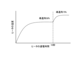
- FIG. 10 is a diagram showing an example of the relationship between heater power-on time and temperature in the hand dryer according to the fourth embodiment; Flowchart showing an example of the procedure of the heater output control method according to the fourth embodiment
- FIG. 1 is a perspective view of a hand dryer according to Embodiment 1.
- FIG. 2 is a cross-sectional view of the hand dryer according to Embodiment 1, and is a cross-sectional view taken along line II-II in FIG.
- the hand dryer 1 includes a housing 3 having a hand insertion portion 2 into which a hand can be inserted.
- the upper portion and both side portions of the hand insertion portion 2 are open. A hand can be inserted into the hand insertion part 2 from the upper part and both sides.
- the housing 3 forms the outer shell of the hand dryer 1 as a whole.
- the front part 4 is a part of the housing 3 and is a part on the front side of the hand insertion part 2 .
- the back portion 5 is a part of the housing 3 and is a portion on the back side of the hand insertion portion 2 .
- the front side is the side where the user using the hand dryer 1 is located when viewed from the hand dryer 1 .
- the back side is the side opposite to the front side when viewed from the hand dryer 1 .
- the water receiving part 6 is located at the lowest part of the hand insertion part 2.
- the water receiving portion 6 is provided with a drain port (not shown) for discharging the received water to the drain tank 7 .
- the housing 3 is provided with a drainage channel (not shown) through which water flows from the drainage port to the drain tank 7 .
- the drain tank 7 stores water from the drainage channel.
- the drain tank 7 is provided on the front side of the lower portion of the housing 3 .
- the drain tank 7 is detachable from the housing 3.
- the hand dryer 1 includes an air blower 10 that generates airflow inside the housing 3 .
- the blower unit 10 is provided inside the housing 3 .
- the air blower 10 includes a motor 21 such as a DC (Direct Current) brushless motor, which is a drive source, and a turbo fan 22 that rotates when the motor 21 is driven.
- An example of the blower 10 is a high-pressure airflow generator.
- the hand dryer 1 includes a front side nozzle 11 and a back side nozzle 12 that jet an air flow to the hand insertion portion 2 .
- the front side nozzle 11 and the back side nozzle 12 correspond to nozzles.
- the front nozzle 11 is provided on the surface of the front portion 4 on the side of the hand insertion portion 2 .
- the back side nozzle 12 is provided on the surface of the back portion 5 on the side of the hand insertion portion 2 .
- the hand dryer 1 jets the airflow that has passed through the duct 13 inside the front part 4 from the blower part 10 to the hand insertion part 2 from the front nozzle 11.
- the hand dryer 1 jets the airflow that has passed through the duct 14 inside the back portion 5 from the air blowing portion 10 to the hand insertion portion 2 from the back side nozzle 12 .
- the hand dryer 1 includes a hand detection section 15 that detects a hand inserted into the hand insertion section 2.
- the hand detection section 15 is built in the back section 5 .
- An example of the hand detection unit 15 is a ranging sensor.
- a distance measuring sensor includes a light emitting element that emits infrared light and a light receiving element that detects infrared light reflected by a hand, which is an object to be measured.
- the hand detection section 15 detects the presence or absence of a hand in the hand insertion section 2 based on the angle of the infrared light incident on the light receiving element.
- the hand detection unit 15 may be a sensor other than a distance measuring sensor as long as it can detect a hand inserted into the hand insertion unit 2 .
- the hand detection section 15 may be built in the front section 4 .
- the hand drying device 1 includes a heater 23 that heats the airflow sent out to the ducts 13,14.
- the heater 23 is provided in an air passage between the air blower 10 and the front nozzle 11 and the rear nozzle 12 .
- the housing 3 has an intake port 16 for sucking air.
- the intake port 16 is provided at the bottom of the housing 3 .
- the air blower 10 takes in an air flow from an air inlet 16 to a duct 17 inside the housing 3 and sends out the air flow from the duct 17 to the ducts 13 and 14 .
- An air filter 18 is attached to the intake port 16 to remove foreign matter from the airflow taken into the duct 17 .
- a control unit 30 that controls the entire hand dryer 1 is provided inside the housing 3 .
- Control unit 30 controls blower unit 10 and heater 23 based on a detection signal from hand detection unit 15 indicating that a hand has been detected. Specifically, when the hand detection unit 15 detects a hand, the control unit 30 energizes the heater 23 and drives the blower unit 10 . When the hand is removed from the hand insertion portion 2 and the hand is no longer detected by the hand detection portion 15 , the control portion 30 stops the heater 23 and the blower portion 10 .
- the high-pressure airflow generated by the air blowing portion 10 is heated by the heater 23, and the front side wall surface of the hand insertion portion 2 is heated. It is guided to the front side nozzle 11 provided and the rear side nozzle 12 provided on the rear side wall surface. Then, high-speed airflow is jetted from the front nozzle 11 and the rear nozzle 12 into the hand inserting portion 2 to blow off the moisture adhering to the hand inserted into the hand inserting portion 2. - ⁇ The blown water is led to a drain tank 7 through a drain port provided in a water receiving part 6 below the hand insertion part 2 and is stored in the drain tank 7. ⁇
- FIG. 3 is a diagram showing an example of the schematic configuration of the circuit of the control unit of the hand dryer according to the first embodiment. Note that FIG. 3 schematically shows the layout of each circuit, and does not show an actual circuit diagram.
- the control unit 30 includes a zero-cross detection circuit 31 , a triac 32 , a DC bus power supply 33 , a voltage detection circuit 34 , a power supply circuit 35 and a microcontroller circuit 36 .
- the microcontroller circuit 36 is hereinafter referred to as microcomputer circuit 36 .
- the zero cross detection circuit 31 is a circuit that detects a zero cross when the AC voltage of the AC power supply 40 becomes zero.
- Triac 32 is an electronic component that drives heater 23 . As shown in FIG. 3, heater 23 is connected in series with triac 32 . Also, the heater 23 is connected to an AC power supply 40 .
- the specifications, that is, the type of the hand dryer 1 differ depending on the voltage of the AC power source 40, but the heater 23 is of the same type regardless of the voltage of the AC power source 40, that is, regardless of the type of the hand dryer 1. is used.
- the DC bus power supply 33 rectifies and smoothes the power supplied from the AC power supply 40 to generate a DC bus voltage.
- the DC bus power supply 33 generates a DC bus voltage corresponding to the effective value of the voltage of the AC power supply 40 .
- the effective value of the voltage of the AC power supply 40 is also called the voltage value of the AC power supply 40 .
- a voltage detection circuit 34 detects the voltage value of the DC bus voltage.
- the voltage detection circuit 34 detects the voltage value of the DC bus voltage, and when the voltage value of the DC bus power supply 33 and the voltage value of the AC power supply 40 are associated, A voltage value of the AC power supply 40 can be estimated.
- the voltage detection circuit 34 may be any circuit that can detect or estimate the voltage value of the AC power supply 40 .
- Voltage detection circuit 34 corresponds to a voltage estimation circuit.
- the power supply circuit 35 is a circuit that generates AC power for driving the motor 21 from the DC bus voltage.
- a motor 21 is connected to the power supply circuit 35 .
- An example of the power supply circuit 35 is an inverter circuit.
- the microcomputer circuit 36 controls energization of the heater 23 according to the voltage value of the AC power supply 40 . Specifically, the microcomputer circuit 36 performs heater control settings, which are settings related to energization of the heater 23 , according to the voltage value of the AC power supply 40 .
- the heater control setting is performed, in one example, when the hand dryer 1 is powered on.
- the microcomputer circuit 36 uses the voltage detection value, which is the voltage of the DC bus power supply 33 detected by the voltage detection circuit 34 , as the voltage value of the AC power supply 40 supplied to the hand dryer 1 .
- the microcomputer circuit 36 determines the energization ratio, which is the ratio of the period of energization to the heater 23 according to the magnitude of the voltage value of the AC power supply 40 in the determined period. This energization rate corresponds to the heater energization rate.
- the defined period can be one cycle of the voltage of the AC power supply 40 .
- the timing of the ON command to the gate of the triac 32 is set so as to achieve the determined energization ratio.
- the energization ratio that is, the setting of the ON command timing is the heater control setting.
- the microcomputer circuit 36 controls the power supply circuit 35 connected to the triac 32 and the motor 21 based on information from the hand detection unit 15, heater control settings, and information from the zero cross detection circuit 31. As a result, blowing of warm air to the hand insertion portion 2 while the hand is being inserted into the hand insertion portion 2 is controlled. Although not shown, the microcomputer circuit 36 is also electrically connected to the hand detection unit 15 shown in FIG. does not exist. The microcomputer circuit 36 corresponds to a control circuit.
- the heater 23 and triac 32 are connected between the AC power supply 40 and the DC bus power supply 33 .
- Zero-cross detection circuit 31 is connected between AC power supply 40 and heater 23 and triac 32 .
- the voltage detection circuit 34 is connected to the output side of the DC bus power supply 33 .
- the microcomputer circuit 36 generates an ON command or an OFF command based on the heater control settings and information from the zero cross detection circuit 31 and outputs it to the gate (not shown) of the triac 32 .
- Triac 32 is turned on or off based on an on command or off command from microcomputer circuit 36 .
- the heater 23 is configured to be driven by phase control.
- FIG. 4 is a diagram for explaining the operating principle of phase control.
- FIG. 4 shows an input voltage waveform VI, a gate input signal GI which is a signal input to the gate of the triac 32, and a voltage waveform VH applied to the heater 23.
- FIG. In these figures, the horizontal axis indicates time.
- the vertical axis of the input voltage waveform VI and the voltage waveform VH applied to the heater 23 indicates voltage
- the vertical axis of the gate input signal GI indicates ON or OFF of the signal.
- the timing at which the triac 32 is turned off is the case where the input voltage waveform VI becomes zero, and the current flowing through the triac 32 becomes zero at this timing. Therefore, the microcomputer circuit 36 does not output the OFF command. That is, the gate input signal GI indicates ON commands GI1, GI2 and GI3 output from the microcomputer circuit 36.
- Phase control is a control method in which the AC voltage is directly turned on or off by the triac 32 to vary the applied voltage. change.
- a power supply zero cross point is a point at which the voltage becomes zero in the input voltage waveform VI.
- the microcomputer circuit 36 outputs ON commands GI1, GI2, and GI3 to the triac 32 every half cycle of the input voltage waveform VI.
- the microcomputer circuit 36 outputs ON commands GI1, GI2 and GI3 at times t1, t3 and t5.
- an ON command GI1 is output from the microcomputer circuit 36 to the gate of the triac 32 at time t1
- the triac 32 is turned on at time t1, and current flows through the triac 32 and the heater 23.
- FIG. After that, at time t2 when the input voltage becomes zero, the triac 32 is turned off and the current does not flow through the heater 23 .
- a voltage is applied to the heater 23 like the voltage waveform VH applied to the heater 23 in FIG. That is, in the half cycle from time t0 to time t2 of the input voltage waveform VI, the voltage is applied to the heater 23 during the time from time t1 to time t2, and the heater 23 is applied during the time from time t0 to time t1. No voltage is applied to
- the voltage is applied to the heater 23 during the time from time t3 to time t4, and the heater 23 is applied during the time from time t2 to time t3. No voltage is applied to Then, such processing is repeatedly performed.
- the voltage applied to the heater 23 can be changed by adjusting the output timing of the ON commands GI1, GI2, and GI3 to the gates, that is, the ON time.
- the microcomputer circuit 36 outputs ON commands GI1, GI2, and GI3 to the gates of the triac 32 at times t0, t2, and t4 so that the input voltage waveform VI turns on at the power supply zero cross point where the voltage becomes zero, , the conduction angle to the heater 23 is 100%. Further, if one cycle of the input voltage waveform VI is 360 degrees, and the ON commands GI1, GI2, and GI3 are output to the gates of the triac 32 at a position 90 degrees ahead of the power supply zero cross point, the conduction angle to the heater 23 is 50%. becomes.
- the energization ratio which is the ratio of the energization period to the heater 23 in one period, which is a predetermined period, is the conduction angle. If the triac 32 is ON in one cycle, ie, the time during which the heater 23 is energized, the power value increases, and if the ON time is short, the power value decreases.
- the ON and OFF timings, that is, the conduction angle can be arbitrarily set by the microcomputer circuit 36 .
- the voltage applied to the heater 23 changes at the timing when the microcomputer circuit 36 outputs the ON commands GI1, GI2, and GI3 to the gate of the triac 32, so the amount of heat generated by the heater 23 also changes.
- the microcomputer circuit 36 acquires the output voltage of the DC bus power supply 33 from the voltage detection circuit 34, and estimates the voltage value of the AC power supply 40 from the output voltage. Also, the microcomputer circuit 36 acquires information from the zero cross detection circuit 31 .
- the information from the zero cross detection circuit 31 includes, for example, the power supply zero cross point, which is the time when the zero cross detection circuit 31 detects the zero cross.
- the microcomputer circuit 36 determines the output timing of the ON commands GI1, GI2 and GI3 to the gates of the triac 32 so that the conduction angle corresponds to the value of the output voltage with reference to the power supply zero cross point.
- the energization rate to the heater 23 may be controlled using energization rate control.
- FIG. 5 is a flow chart showing an example of the procedure of the control method for the hand dryer according to Embodiment 1.
- the voltage value of the AC power supply 40 is either a 100V system AC power supply that supplies an AC voltage between 100V and 200V, or a 200V system AC power supply that supplies an AC voltage between 200V and 240V. Assume that there is
- the voltage detection circuit 34 detects the voltage of the DC bus power supply 33 and outputs the voltage detection value, which is the detection result, to the microcomputer circuit 36 (step S11). Since the voltage value of the DC bus power supply 33 changes according to the voltage value of the AC power supply 40 , the voltage value of the AC power supply 40 can be estimated from the voltage detection value of the DC bus power supply 33 .
- the microcomputer circuit 36 Upon receiving the voltage detection value from the voltage detection circuit 34, the microcomputer circuit 36 performs heater control setting (step S12).
- the heater control setting is, as described above, the setting of the conduction angle and the setting of the output timing of the ON command to the gate of the triac 32 .
- the microcomputer circuit 36 holds heater control setting information in which the voltage detection value and the conduction angle are associated with each other, acquires the conduction angle corresponding to the voltage detection value from the heater control setting information, and based on the conduction angle, settings.
- FIG. 6 is a diagram showing an example of heater control setting information.
- the heater control setting information is associated with the voltage detection value of the DC bus power supply 33 and the conduction angle.
- the voltage detection value range and the conduction angle are associated with each other. Specifically, when the voltage detection value of the DC bus power supply 33 is 150V or less, the conduction angle is 100%, and when the voltage detection value is greater than 150V, the conduction angle is 50%.
- the AC power supply 40 is a 100 V AC power supply, and when the voltage detection value is greater than 150 V, the AC power supply 40 is a 200 V AC power supply. . In this manner, the smaller the voltage value of the AC power supply 40, the larger the conduction angle, that is, the energization ratio.
- the conduction angle is 100% in FIG. 6, but the conduction angle may be 50%.
- 150 V in the heater control setting information is a reference value for dividing the setting of the conduction angle, and corresponds to the reference value. Although the reference value here is 150V, this is an example and other values may be used.
- the conduction angle in FIG. 6 is also an example and can be set to any value. However, the conduction angle is set to increase as the voltage value of the AC power supply 40 decreases.
- the microcomputer circuit 36 determines that the model is compatible with a 100 V AC power source, that is, that the device is connected to a 100 V AC power source, and refers to the heater control setting information to determine the conduction angle. to 100%. If the voltage detection value is greater than 150 V, the microcomputer circuit 36 determines that the model is compatible with a 200 V AC power source, that is, that the device is connected to a 200 V AC power source, and refers to the heater control setting information. to set the conduction angle to 50%.
- the microcomputer circuit 36 determines whether the hand detection unit 15 has detected a hand (step S13). If the hand is not detected (No in step S13), the process enters a waiting state.
- the microcomputer circuit 36 drives the heater according to the heater control setting set in step S12. is started (step S14). That is, the microcomputer circuit 36 starts power supply control to the heater 23 .
- the microcomputer circuit 36 when the microcomputer circuit 36 receives information from the zero-cross detection circuit 31 indicating that the power supply zero-cross point has been detected, the microcomputer circuit 36 outputs an ON command to the triac 32 after a time corresponding to the conduction angle has elapsed after receiving the detection signal. output to the gate of When an ON command is input to the gate of the triac 32 , the triac 32 is energized and a voltage is applied to the heater 23 . After that, when the input voltage from the AC power supply 40 becomes zero, the current flowing through the triac 32 becomes zero, and the voltage applied to the heater 23 becomes zero. At this time, the zero cross detection circuit 31 detects the power supply zero cross point and notifies the microcomputer circuit 36 of the detection signal. In this way, the process of applying voltage to the heater 23 is repeatedly executed from when the ON command is received until the input voltage becomes zero.
- the microcomputer circuit 36 starts driving the motor (step S15).
- the microcomputer circuit 36 controls the conduction angle to the motor 21 to be a predetermined value.
- the high-pressure airflow generated by the air blower 10 and heated by the heater 23 is jetted toward the hand as a high-speed airflow from the front nozzle 11 and the rear nozzle 12 of the hand insertion unit 2. .
- the microcomputer circuit 36 determines whether the hand is no longer detected by the hand detection unit 15 (step S16). If the hand is detected (No in step S16), the state of jetting the heated high-speed airflow toward the hand is continued. When the hand is no longer detected (Yes in step S16), that is, when the hand is removed from the hand insertion portion 2, the microcomputer circuit 36 stops driving the heater (step S17). 36 stops the motor drive (step S18). Then, the process returns to step S13.
- the zero cross detection circuit 31 that detects the power supply zero cross point in the AC power supply 40
- the voltage detection circuit 34 that detects the voltage value of the DC bus power supply 33 that converts the AC power supply 40 into DC power supply.
- a triac 32 connected in series with the heater 23
- a microcomputer circuit 36 that controls the voltage applied to the heater 23 according to the voltage detection value in the voltage detection circuit 34 .
- the microcomputer circuit 36 sets the conduction angle to the heater 23 according to the magnitude of the detected voltage value. The conduction angle is set such that when the voltage detection value is large, the conduction angle is smaller than when the voltage detection value is small.
- the microcomputer circuit 36 drives the heater 23 when the hand is inserted into the hand insertion portion 2 .
- the microcomputer circuit 36 receives the information indicating that the zero cross has been detected from the zero cross detection circuit 31, after the time corresponding to the set conduction angle has elapsed, the microcomputer circuit 36 outputs an ON command to the triac 32, and the heater 23 AC voltage is applied to Then, when the AC voltage becomes zero, the AC voltage applied to the heater 23 becomes zero. In this manner, the AC voltage can be applied to the heater 23 during the period corresponding to the set conduction angle in the cycle of the AC voltage. That is, an AC voltage can be applied to the heater 23 according to the voltage value of the AC power supply 40 so that the airflow reaches the target temperature.
- the conduction angle to the heater 23 is set large.
- the voltage detection value is high, for example, when the hand dryer 1 is a model compatible with a 200V AC power supply, that is, when it is connected to a 200V AC power supply, the conduction angle to the heater 23 is set small. Thereby, even if the voltage value of the AC power supply 40 is different, the heating performance of the common heater 23 can be maintained at the same level. In other words, the heater 23 can be shared between models of the hand dryer 1 corresponding to the type of the AC power supply 40 . As a result, there is an effect that the heater 23 can be shared among products with different power supply voltages of the AC power supply 40 without using heaters 23 with different specifications for each power supply voltage of the AC power supply 40 .
- Embodiment 2 shows a case where the conduction angle is changed when the heater 23 is driven.
- the microcomputer circuit 36 sets, as the target conduction angle, the conduction angle, which is the ratio of energization to the heater 23 set with respect to the magnitude of the voltage value of the AC power supply 40. Electricity to the heater 23 is started at the conduction angle, and the conduction angle is changed to the target conduction angle after a predetermined time has elapsed. That is, the conduction angle in the heater control setting information becomes the target set value. Then, the microcomputer circuit 36 makes the conduction angle larger than the target set value when the heater 23 starts to be driven, and gradually reduces it to the target set value.
- the timing, time, etc., for changing the conduction angle can be set arbitrarily.
- FIG. 7 is a diagram showing an example of the relationship between heater energization time and temperature in the hand dryer according to the second embodiment.
- the horizontal axis indicates the energization time of the heater 23
- the vertical axis indicates the temperature of the heater 23.
- a graph G1 represented by a solid line shows the relationship between the energization time and the temperature until the target temperature is reached when the conduction angle is set to 50% in the model compatible with the 200V AC power supply in the first embodiment.
- Graph G2 indicated by a dashed line shows the energization time and temperature until the target temperature is reached when the conduction angle is gradually decreased to the target setting value in a model compatible with a 200V AC power supply. shows the relationship between In graph G2, the target conduction angle setting is 50%, but the conduction angle is changed in the order of 100% ⁇ 90% ⁇ 80% ⁇ . . . 50%.
- the conduction angle is controlled to be constant without changing, the temperature of the heater 23 gradually rises with the energization time and reaches the target temperature.
- the conduction angle is set larger than the target set value at the start of energization, and is gradually reduced to the target set value, so that the temperature rises sharply at startup. Therefore, it is possible to quickly reach the target temperature.
- the conduction angle is gradually reduced from a large value to the target set value.
- the conduction angle lower than 100% is the target setting value
- the target temperature is reached more quickly than when the conduction angle is set at the target setting value and the energization of the heater 23 is started. can save time. That is, in the first embodiment, it takes time for the heater 23 to warm up. can be done. Therefore, it is possible to dry the user's hands more quickly.
- the number of steps for reducing the conduction angle may be one or more.
- the set value after energizing the heater 23 at a conduction angle larger than the target set value for a predetermined time, the set value may be changed to the target set value.
- the above example is effective when the heater 23 for a model compatible with a 100V system AC power supply is used in the hand dryer 1 and a 200V system AC power supply is applied to the heater 23 .
- the effect of shortening the heating time can be expected even when a 100V system AC power source is applied by selecting a heater 23 that generates a higher amount of heat.
- Embodiment 1 shows the case where the microcomputer circuit 36 drives the motor 21 so that the conduction angle to the motor 21 becomes a predetermined constant value.
- Embodiment 3 shows a case where the conduction angle to the motor 21 is changed together with the heater 23 .
- the configuration of the hand dryer 1 according to Embodiment 3 is the same as that shown in Embodiments 1 and 2, but the function of the microcomputer circuit 36 in the control section 30 is different from those in Embodiments 1 and 2. Differences from the first and second embodiments will be described below. Moreover, below, the hand dryer 1 is demonstrated as what has the structure of Embodiment 2. As shown in FIG.
- the microcomputer circuit 36 changes the conduction angle to the motor 21, which is the ratio of the energization period to the motor 21 in a predetermined period, in accordance with the change in the conduction angle, which is the energization ratio to the heater 23. Increase gradually.
- the conduction angle to the motor 21 corresponds to the motor energization ratio. That is, the microcomputer circuit 36 gradually increases the conduction angle to the motor 21 as the conduction angle to the heater 23 gradually decreases toward the target set value.
- FIG. 8 is a diagram showing an example of the relationship between energization time and power consumption in the hand dryer according to the second embodiment.
- the horizontal axis indicates the energization time
- the vertical axis indicates the power consumption.
- a graph G11 indicated by a solid line indicates the power consumption when the motor 21 is driven with a constant conduction angle
- a graph G12 indicated by a broken line indicates the power consumption when the conduction angle to the heater 23 is gradually decreased. showing power.
- a graph G ⁇ b>13 represented by a one-dot chain line indicates the power consumption of the entire load, which is obtained by synthesizing the power consumption of the motor 21 and the power consumption of the heater 23 .
- the conduction angle to the heater 23 is large, so the power consumed by the heater 23 is the maximum during the energization time.
- the power consumption of the entire load obtained by combining the power consumption of the motor 21 and the heater 23 has a large power value at the start of energization, as shown in the graph G13.
- FIG. 9 is a diagram showing an example of the relationship between energization time and power consumption in the hand dryer according to the third embodiment.
- the horizontal axis indicates the energization time
- the vertical axis indicates the power consumption.
- a graph G21 indicated by a solid line shows power consumption when the conduction angle to the motor 21 is gradually increased
- a graph G22 indicated by a broken line is when the conduction angle to the heater 23 is gradually decreased.
- power consumption A graph G ⁇ b>23 represented by a one-dot chain line indicates the power consumption of the entire load, which is obtained by synthesizing the power consumption of the motor 21 and the power consumption of the heater 23 .
- FIG. 9 is a diagram showing an example of the relationship between energization time and power consumption in the hand dryer according to the third embodiment.
- the horizontal axis indicates the energization time
- the vertical axis indicates the power consumption.
- a graph G21 indicated by a solid line shows power consumption when the conduction angle to the
- the conduction angle to the heater 23 is large, so the power consumed by the heater 23 is the maximum during the energization time.
- the conduction angle to the motor 21 is gradually increased as the conduction angle to the heater 23 gradually decreases, as shown in the graph G21.
- the conduction angle to the heater 23 gradually increases from a value larger than the target set value to the target set value.
- the conduction angle to the motor 21 is gradually increased from a value smaller than a predetermined value to a predetermined value.
- the conduction angle to the motor 21 is controlled, but the conduction angle to the motor 21 may be controlled using phase control, duty ratio control, inverter control, or the like.
- Embodiment 4 In the first embodiment, when the conduction angle is set for the voltage detection value detected by the voltage detection circuit 34, the conduction angle is kept constant when the heater 23 is subsequently driven. Further, in the second embodiment, when the heater 23 is driven, the conduction angle is gradually decreased so as to reach the target set value. Embodiment 4 shows a case in which the conduction angle to the heater 23 is increased when the heater 23 is energized for a period longer than a predetermined period.
- the configuration of the hand dryer 1 according to Embodiment 4 is the same as that shown in Embodiments 1 to 3, but the function of the microcomputer circuit 36 in the control section 30 is different from those in Embodiments 1 to 3. Differences from Embodiments 1 to 3 will be described below. Moreover, below, the hand dryer 1 is demonstrated as what has the structure of Embodiment 2. As shown in FIG. In the fourth embodiment, the microcomputer circuit 36 measures time from the start of energization of the heater 23, and when the energization time of the heater 23 elapses and the energization of the heater 23 continues, , the conduction angle to the heater 23 is increased.
- the drying time after washing your hands may vary depending on the season or how you wash your hands. In addition, there are individual differences in recognition that the hands are sufficiently dry depending on the user. If the hands are not sufficiently dried even after a certain period of time has passed, or if the user feels that the hands are not sufficiently dried, the usage time of the hand dryer 1 is extended. Therefore, if the drying of the hands continues after a predetermined time has passed, the microcomputer circuit 36 determines that the drying is insufficient, and further increases the temperature of the heater 23 . In other words, the conduction angle to the heater 23 is raised above the target set value. This improves the user's feeling of warm air and shortens the drying time.
- FIG. 10 is a diagram showing an example of the relationship between heater energization time and temperature in the hand dryer according to the fourth embodiment.
- the horizontal axis indicates the energization time of the heater 23, and the vertical axis indicates the temperature of the heater 23.
- the conduction angle is gradually changed from 100% to the target set value of 50%, as described in the second embodiment.
- the microcomputer circuit 36 determines whether the hand is still inserted into the hand insertion portion 2 even after 10 seconds have elapsed since the heater 23 was turned on, that is, when the heater 23 continues to be energized.
- the set value of the conduction angle to the heater 23 is increased.
- the conduction angle to the heater 23 is changed from 50% to 75%. Note that FIG. 10 shows an example in which the set value of the conduction angle is increased for 10 seconds, but this is just an example, and any time can be set.
- FIG. 11 is a flow chart showing an example of the procedure of the heater output control method according to the fourth embodiment.
- the same step numbers are assigned to the same processes as in FIG. 5 of the first embodiment, and the description thereof is omitted.
- the microcomputer circuit 36 starts timing when heater driving is started in step S14 (step S31).
- step S16 determines whether a hand is detected in step S16 (No in step S16). If the predetermined time has not elapsed (No in step S32), the process returns to step S16. If the predetermined time has passed (Yes in step S32), the microcomputer circuit 36 increases the conduction angle to the heater 23 from the current value (step S33). After that, the microcomputer circuit 36 determines whether the hand is no longer detected by the hand detection unit 15 (step S34). If the hand is detected (No in step S34), the state of jetting the heated high-speed airflow toward the hand is continued. If the hand is no longer detected (Yes in step S34), the process proceeds to step S17.
- the angle of conduction to the heater 23 is increased, and the air at a higher speed than before the angle of conduction to the heater 23 is increased.
- the temperature of the stream can be increased to improve the feeling of warm air to the user.
- the microcomputer circuit 36 shows a method of changing the set value so that the conduction angle is determined when the hand is inserted for a predetermined period of time or longer.
- the microcomputer circuit 36 controls the conduction angle to the heater 23 so as to gradually increase to the prescribed conduction angle when the electricity supply time to the heater 23 elapses. may As a result, the feeling of warm air can be improved without causing the user to feel uncomfortable due to sudden temperature changes.
- the microcomputer circuit 36 starts timing when the heater 23 is energized, and increases the conduction angle to the heater 23 when the heater 23 is energized for a predetermined time or longer. I made it As a result, when the hands are not sufficiently dried, or when the user feels that the hands are not sufficiently dried, the feeling of warm air can be improved.
- 1 hand drying device 2 hand insertion part, 3 housing, 4 front part, 5 back part, 6 water receiving part, 7 drain tank, 10 blower part, 11 front nozzle, 12 rear nozzle, 13, 14, 17 Duct, 15 hand detection unit, 16 intake port, 18 air filter, 21 motor, 22 turbo fan, 23 heater, 30 control unit, 31 zero cross detection circuit, 32 triac, 33 DC bus power supply, 34 voltage detection circuit, 35 power supply circuit , 36 Microcomputer circuit, 40 AC power supply.
Landscapes
- Health & Medical Sciences (AREA)
- Public Health (AREA)
- Control Of Resistance Heating (AREA)
Priority Applications (2)
| Application Number | Priority Date | Filing Date | Title |
|---|---|---|---|
| PCT/JP2021/045484 WO2023105743A1 (ja) | 2021-12-10 | 2021-12-10 | 手乾燥装置 |
| JP2023565832A JP7630649B2 (ja) | 2021-12-10 | 2021-12-10 | 手乾燥装置 |
Applications Claiming Priority (1)
| Application Number | Priority Date | Filing Date | Title |
|---|---|---|---|
| PCT/JP2021/045484 WO2023105743A1 (ja) | 2021-12-10 | 2021-12-10 | 手乾燥装置 |
Publications (1)
| Publication Number | Publication Date |
|---|---|
| WO2023105743A1 true WO2023105743A1 (ja) | 2023-06-15 |
Family
ID=86729970
Family Applications (1)
| Application Number | Title | Priority Date | Filing Date |
|---|---|---|---|
| PCT/JP2021/045484 Ceased WO2023105743A1 (ja) | 2021-12-10 | 2021-12-10 | 手乾燥装置 |
Country Status (2)
| Country | Link |
|---|---|
| JP (1) | JP7630649B2 (https=) |
| WO (1) | WO2023105743A1 (https=) |
Citations (5)
| Publication number | Priority date | Publication date | Assignee | Title |
|---|---|---|---|---|
| JP2000316280A (ja) * | 1999-04-27 | 2000-11-14 | Sony Corp | 電源装置 |
| JP2001327433A (ja) * | 2000-05-25 | 2001-11-27 | Matsushita Electric Ind Co Ltd | 手乾燥装置 |
| JP2006097924A (ja) * | 2004-09-28 | 2006-04-13 | Matsushita Electric Ind Co Ltd | 換気装置 |
| JP2007117243A (ja) * | 2005-10-26 | 2007-05-17 | Matsushita Electric Ind Co Ltd | 暖房便座 |
| WO2015128988A1 (ja) * | 2014-02-27 | 2015-09-03 | 三菱電機株式会社 | 手乾燥装置 |
-
2021
- 2021-12-10 WO PCT/JP2021/045484 patent/WO2023105743A1/ja not_active Ceased
- 2021-12-10 JP JP2023565832A patent/JP7630649B2/ja active Active
Patent Citations (5)
| Publication number | Priority date | Publication date | Assignee | Title |
|---|---|---|---|---|
| JP2000316280A (ja) * | 1999-04-27 | 2000-11-14 | Sony Corp | 電源装置 |
| JP2001327433A (ja) * | 2000-05-25 | 2001-11-27 | Matsushita Electric Ind Co Ltd | 手乾燥装置 |
| JP2006097924A (ja) * | 2004-09-28 | 2006-04-13 | Matsushita Electric Ind Co Ltd | 換気装置 |
| JP2007117243A (ja) * | 2005-10-26 | 2007-05-17 | Matsushita Electric Ind Co Ltd | 暖房便座 |
| WO2015128988A1 (ja) * | 2014-02-27 | 2015-09-03 | 三菱電機株式会社 | 手乾燥装置 |
Also Published As
| Publication number | Publication date |
|---|---|
| JPWO2023105743A1 (https=) | 2023-06-15 |
| JP7630649B2 (ja) | 2025-02-17 |
Similar Documents
| Publication | Publication Date | Title |
|---|---|---|
| CN113491463B (zh) | 干燥装置 | |
| JP2011019606A (ja) | 手乾燥装置 | |
| JP7630649B2 (ja) | 手乾燥装置 | |
| JP2001346715A (ja) | 手乾燥装置 | |
| CN107708510B (zh) | 手干燥装置 | |
| WO2019186793A1 (ja) | 手乾燥装置及び手乾燥装置の異常検知方法 | |
| JP5953883B2 (ja) | 浴室衣類乾燥装置 | |
| JP6464959B2 (ja) | 浴室乾燥装置 | |
| JP6103468B2 (ja) | 手乾燥装置 | |
| JP5127952B2 (ja) | 手乾燥装置 | |
| WO2020161866A1 (ja) | 手乾燥装置 | |
| JP2014121425A (ja) | 浴室暖房乾燥機 | |
| JP2783078B2 (ja) | 手乾燥装置 | |
| KR20230053337A (ko) | 김서림 자동 제거기능을 갖는 거울 | |
| JPWO2018189788A1 (ja) | 手乾燥装置 | |
| JP7309082B2 (ja) | 手乾燥装置 | |
| JP2017218864A (ja) | 温水洗浄便座装置 | |
| JP6682918B2 (ja) | 手乾燥装置 | |
| JP2017056032A (ja) | 手乾燥装置 | |
| JP6221052B2 (ja) | 手乾燥装置 | |
| JP5975416B2 (ja) | 手乾燥装置 | |
| JP3968822B2 (ja) | 手乾燥装置 | |
| JP6277411B2 (ja) | 浴室暖房乾燥機 | |
| JP2007202828A (ja) | 食器洗浄機 | |
| JP2551694B2 (ja) | 局部洗浄装置 |
Legal Events
| Date | Code | Title | Description |
|---|---|---|---|
| 121 | Ep: the epo has been informed by wipo that ep was designated in this application |
Ref document number: 21967237 Country of ref document: EP Kind code of ref document: A1 |
|
| WWE | Wipo information: entry into national phase |
Ref document number: 2023565832 Country of ref document: JP |
|
| NENP | Non-entry into the national phase |
Ref country code: DE |
|
| 122 | Ep: pct application non-entry in european phase |
Ref document number: 21967237 Country of ref document: EP Kind code of ref document: A1 |