WO2023105743A1 - 手乾燥装置 - Google Patents
手乾燥装置 Download PDFInfo
- Publication number
- WO2023105743A1 WO2023105743A1 PCT/JP2021/045484 JP2021045484W WO2023105743A1 WO 2023105743 A1 WO2023105743 A1 WO 2023105743A1 JP 2021045484 W JP2021045484 W JP 2021045484W WO 2023105743 A1 WO2023105743 A1 WO 2023105743A1
- Authority
- WO
- WIPO (PCT)
- Prior art keywords
- heater
- hand
- energization
- power supply
- voltage
- Prior art date
Links
- 238000001514 detection method Methods 0.000 claims abstract description 77
- 238000003780 insertion Methods 0.000 claims abstract description 37
- 230000037431 insertion Effects 0.000 claims abstract description 37
- 238000010438 heat treatment Methods 0.000 claims description 4
- 239000007921 spray Substances 0.000 abstract 1
- 238000000034 method Methods 0.000 description 21
- 238000010586 diagram Methods 0.000 description 15
- 238000001035 drying Methods 0.000 description 9
- XLYOFNOQVPJJNP-UHFFFAOYSA-N water Substances O XLYOFNOQVPJJNP-UHFFFAOYSA-N 0.000 description 9
- 230000003247 decreasing effect Effects 0.000 description 6
- 238000007664 blowing Methods 0.000 description 5
- 230000007423 decrease Effects 0.000 description 4
- 238000005406 washing Methods 0.000 description 4
- 230000000694 effects Effects 0.000 description 3
- 230000005611 electricity Effects 0.000 description 2
- 238000005516 engineering process Methods 0.000 description 2
- 230000002028 premature Effects 0.000 description 2
- 230000002194 synthesizing effect Effects 0.000 description 2
- 230000006866 deterioration Effects 0.000 description 1
- 238000007599 discharging Methods 0.000 description 1
- 238000004904 shortening Methods 0.000 description 1
Images


Classifications
-
- A—HUMAN NECESSITIES
- A47—FURNITURE; DOMESTIC ARTICLES OR APPLIANCES; COFFEE MILLS; SPICE MILLS; SUCTION CLEANERS IN GENERAL
- A47K—SANITARY EQUIPMENT NOT OTHERWISE PROVIDED FOR; TOILET ACCESSORIES
- A47K10/00—Body-drying implements; Toilet paper; Holders therefor
- A47K10/48—Drying by means of hot air
Definitions
- the present disclosure relates to a hand drying device that dries wet hands by blowing an air stream.
- the hand dryer When a hand is detected in the hand insertion part of the hand dryer, the hand dryer activates the air blower to suck air from the suction port, heats the air sucked from the suction port with the heater, and discharges the heated air. It is sprayed from a nozzle provided in the hand insertion part. At this time, the hands can be dried more quickly by using warm air, which is a flow of air heated by a heater, compared to the case of using low-temperature air.
- An AC power supply is used to power the heater of the hand dryer.
- AC power supplies include a 100V system AC power supply that supplies an AC voltage between 100V and 120V, and a 200V system AC power supply that supplies an AC voltage between 200V and 240V.
- heaters with different specifications are used depending on the power supply voltage. That is, a hand dryer used with a 100V AC power supply is equipped with a 100V heater, and a hand dryer used with a 200V AC power supply is equipped with a 200V heater. Preparing products with different specifications according to the voltage value of the AC power supply causes an increase in the number of models and an increase in cost.
- Patent Document 1 discloses a method of sharing a motor regardless of the power supply voltage.
- a power supply device configured to detect the voltage value of an AC voltage, switch between voltage doubler rectification and full-wave rectification according to the voltage value, generate a DC voltage of the same voltage value, and supply it to a load. is disclosed.
- a DC load of the same specification that is, a motor.
- Patent Document 1 is for standardizing the loads used in direct current, and cannot standardize the loads used in alternating current. In other words, the technology described in Patent Document 1 cannot be applied to common heaters in hand dryers. As described above, in the hand dryer, heaters to which AC voltage is applied must have different specifications for each type of power supply voltage, so it is difficult to standardize the heater regardless of the model. . As a result, there is a problem that the number of models of hand dryers and cost increase.
- the present disclosure has been made in view of the above, and is a hand dryer that can share heaters between products with different types of power supply voltages without using heaters with different specifications for each type of power supply voltage. Aimed at obtaining a device.
- the hand dryer of the present disclosure includes a housing having a hand insertion portion, a nozzle for injecting an air flow to the hand insertion portion, and an air blower for generating the air flow.
- a heater connected to an AC power supply for heating the airflow; a hand detection unit for detecting the hand inserted into the hand insertion unit; and a control unit that controls the blower unit and the heater.
- the control unit has a voltage estimation circuit that estimates the voltage value of the AC power supply, and a control circuit that controls energization of the heater according to the voltage value.
- the hand drying apparatus has the effect of allowing products with different types of power supply voltages to share heaters without using heaters with different specifications for each type of power supply voltage.
- a perspective view of a hand dryer according to Embodiment 1 Sectional view of hand dryer according to Embodiment 1 1 is a diagram showing an example of a schematic configuration of a circuit of a control unit of a hand dryer according to Embodiment 1;
- FIG. Diagram for explaining the operating principle of phase control Flowchart showing an example of the procedure of the control method for the hand dryer according to the first embodiment
- a diagram showing an example of heater control setting information FIG. 10 is a diagram showing an example of the relationship between heater energization time and temperature in the hand dryer according to the second embodiment;
- FIG. 10 is a diagram showing an example of the relationship between power supply time and power consumption in the hand dryer according to the second embodiment;
- FIG. 11 is a diagram showing an example of the relationship between power supply time and power consumption in the hand dryer according to the third embodiment;
- FIG. 10 is a diagram showing an example of the relationship between heater power-on time and temperature in the hand dryer according to the fourth embodiment; Flowchart showing an example of the procedure of the heater output control method according to the fourth embodiment
- FIG. 1 is a perspective view of a hand dryer according to Embodiment 1.
- FIG. 2 is a cross-sectional view of the hand dryer according to Embodiment 1, and is a cross-sectional view taken along line II-II in FIG.
- the hand dryer 1 includes a housing 3 having a hand insertion portion 2 into which a hand can be inserted.
- the upper portion and both side portions of the hand insertion portion 2 are open. A hand can be inserted into the hand insertion part 2 from the upper part and both sides.
- the housing 3 forms the outer shell of the hand dryer 1 as a whole.
- the front part 4 is a part of the housing 3 and is a part on the front side of the hand insertion part 2 .
- the back portion 5 is a part of the housing 3 and is a portion on the back side of the hand insertion portion 2 .
- the front side is the side where the user using the hand dryer 1 is located when viewed from the hand dryer 1 .
- the back side is the side opposite to the front side when viewed from the hand dryer 1 .
- the water receiving part 6 is located at the lowest part of the hand insertion part 2.
- the water receiving portion 6 is provided with a drain port (not shown) for discharging the received water to the drain tank 7 .
- the housing 3 is provided with a drainage channel (not shown) through which water flows from the drainage port to the drain tank 7 .
- the drain tank 7 stores water from the drainage channel.
- the drain tank 7 is provided on the front side of the lower portion of the housing 3 .
- the drain tank 7 is detachable from the housing 3.
- the hand dryer 1 includes an air blower 10 that generates airflow inside the housing 3 .
- the blower unit 10 is provided inside the housing 3 .
- the air blower 10 includes a motor 21 such as a DC (Direct Current) brushless motor, which is a drive source, and a turbo fan 22 that rotates when the motor 21 is driven.
- An example of the blower 10 is a high-pressure airflow generator.
- the hand dryer 1 includes a front side nozzle 11 and a back side nozzle 12 that jet an air flow to the hand insertion portion 2 .
- the front side nozzle 11 and the back side nozzle 12 correspond to nozzles.
- the front nozzle 11 is provided on the surface of the front portion 4 on the side of the hand insertion portion 2 .
- the back side nozzle 12 is provided on the surface of the back portion 5 on the side of the hand insertion portion 2 .
- the hand dryer 1 jets the airflow that has passed through the duct 13 inside the front part 4 from the blower part 10 to the hand insertion part 2 from the front nozzle 11.
- the hand dryer 1 jets the airflow that has passed through the duct 14 inside the back portion 5 from the air blowing portion 10 to the hand insertion portion 2 from the back side nozzle 12 .
- the hand dryer 1 includes a hand detection section 15 that detects a hand inserted into the hand insertion section 2.
- the hand detection section 15 is built in the back section 5 .
- An example of the hand detection unit 15 is a ranging sensor.
- a distance measuring sensor includes a light emitting element that emits infrared light and a light receiving element that detects infrared light reflected by a hand, which is an object to be measured.
- the hand detection section 15 detects the presence or absence of a hand in the hand insertion section 2 based on the angle of the infrared light incident on the light receiving element.
- the hand detection unit 15 may be a sensor other than a distance measuring sensor as long as it can detect a hand inserted into the hand insertion unit 2 .
- the hand detection section 15 may be built in the front section 4 .
- the hand drying device 1 includes a heater 23 that heats the airflow sent out to the ducts 13,14.
- the heater 23 is provided in an air passage between the air blower 10 and the front nozzle 11 and the rear nozzle 12 .
- the housing 3 has an intake port 16 for sucking air.
- the intake port 16 is provided at the bottom of the housing 3 .
- the air blower 10 takes in an air flow from an air inlet 16 to a duct 17 inside the housing 3 and sends out the air flow from the duct 17 to the ducts 13 and 14 .
- An air filter 18 is attached to the intake port 16 to remove foreign matter from the airflow taken into the duct 17 .
- a control unit 30 that controls the entire hand dryer 1 is provided inside the housing 3 .
- Control unit 30 controls blower unit 10 and heater 23 based on a detection signal from hand detection unit 15 indicating that a hand has been detected. Specifically, when the hand detection unit 15 detects a hand, the control unit 30 energizes the heater 23 and drives the blower unit 10 . When the hand is removed from the hand insertion portion 2 and the hand is no longer detected by the hand detection portion 15 , the control portion 30 stops the heater 23 and the blower portion 10 .
- the high-pressure airflow generated by the air blowing portion 10 is heated by the heater 23, and the front side wall surface of the hand insertion portion 2 is heated. It is guided to the front side nozzle 11 provided and the rear side nozzle 12 provided on the rear side wall surface. Then, high-speed airflow is jetted from the front nozzle 11 and the rear nozzle 12 into the hand inserting portion 2 to blow off the moisture adhering to the hand inserted into the hand inserting portion 2. - ⁇ The blown water is led to a drain tank 7 through a drain port provided in a water receiving part 6 below the hand insertion part 2 and is stored in the drain tank 7. ⁇
- FIG. 3 is a diagram showing an example of the schematic configuration of the circuit of the control unit of the hand dryer according to the first embodiment. Note that FIG. 3 schematically shows the layout of each circuit, and does not show an actual circuit diagram.
- the control unit 30 includes a zero-cross detection circuit 31 , a triac 32 , a DC bus power supply 33 , a voltage detection circuit 34 , a power supply circuit 35 and a microcontroller circuit 36 .
- the microcontroller circuit 36 is hereinafter referred to as microcomputer circuit 36 .
- the zero cross detection circuit 31 is a circuit that detects a zero cross when the AC voltage of the AC power supply 40 becomes zero.
- Triac 32 is an electronic component that drives heater 23 . As shown in FIG. 3, heater 23 is connected in series with triac 32 . Also, the heater 23 is connected to an AC power supply 40 .
- the specifications, that is, the type of the hand dryer 1 differ depending on the voltage of the AC power source 40, but the heater 23 is of the same type regardless of the voltage of the AC power source 40, that is, regardless of the type of the hand dryer 1. is used.
- the DC bus power supply 33 rectifies and smoothes the power supplied from the AC power supply 40 to generate a DC bus voltage.
- the DC bus power supply 33 generates a DC bus voltage corresponding to the effective value of the voltage of the AC power supply 40 .
- the effective value of the voltage of the AC power supply 40 is also called the voltage value of the AC power supply 40 .
- a voltage detection circuit 34 detects the voltage value of the DC bus voltage.
- the voltage detection circuit 34 detects the voltage value of the DC bus voltage, and when the voltage value of the DC bus power supply 33 and the voltage value of the AC power supply 40 are associated, A voltage value of the AC power supply 40 can be estimated.
- the voltage detection circuit 34 may be any circuit that can detect or estimate the voltage value of the AC power supply 40 .
- Voltage detection circuit 34 corresponds to a voltage estimation circuit.
- the power supply circuit 35 is a circuit that generates AC power for driving the motor 21 from the DC bus voltage.
- a motor 21 is connected to the power supply circuit 35 .
- An example of the power supply circuit 35 is an inverter circuit.
- the microcomputer circuit 36 controls energization of the heater 23 according to the voltage value of the AC power supply 40 . Specifically, the microcomputer circuit 36 performs heater control settings, which are settings related to energization of the heater 23 , according to the voltage value of the AC power supply 40 .
- the heater control setting is performed, in one example, when the hand dryer 1 is powered on.
- the microcomputer circuit 36 uses the voltage detection value, which is the voltage of the DC bus power supply 33 detected by the voltage detection circuit 34 , as the voltage value of the AC power supply 40 supplied to the hand dryer 1 .
- the microcomputer circuit 36 determines the energization ratio, which is the ratio of the period of energization to the heater 23 according to the magnitude of the voltage value of the AC power supply 40 in the determined period. This energization rate corresponds to the heater energization rate.
- the defined period can be one cycle of the voltage of the AC power supply 40 .
- the timing of the ON command to the gate of the triac 32 is set so as to achieve the determined energization ratio.
- the energization ratio that is, the setting of the ON command timing is the heater control setting.
- the microcomputer circuit 36 controls the power supply circuit 35 connected to the triac 32 and the motor 21 based on information from the hand detection unit 15, heater control settings, and information from the zero cross detection circuit 31. As a result, blowing of warm air to the hand insertion portion 2 while the hand is being inserted into the hand insertion portion 2 is controlled. Although not shown, the microcomputer circuit 36 is also electrically connected to the hand detection unit 15 shown in FIG. does not exist. The microcomputer circuit 36 corresponds to a control circuit.
- the heater 23 and triac 32 are connected between the AC power supply 40 and the DC bus power supply 33 .
- Zero-cross detection circuit 31 is connected between AC power supply 40 and heater 23 and triac 32 .
- the voltage detection circuit 34 is connected to the output side of the DC bus power supply 33 .
- the microcomputer circuit 36 generates an ON command or an OFF command based on the heater control settings and information from the zero cross detection circuit 31 and outputs it to the gate (not shown) of the triac 32 .
- Triac 32 is turned on or off based on an on command or off command from microcomputer circuit 36 .
- the heater 23 is configured to be driven by phase control.
- FIG. 4 is a diagram for explaining the operating principle of phase control.
- FIG. 4 shows an input voltage waveform VI, a gate input signal GI which is a signal input to the gate of the triac 32, and a voltage waveform VH applied to the heater 23.
- FIG. In these figures, the horizontal axis indicates time.
- the vertical axis of the input voltage waveform VI and the voltage waveform VH applied to the heater 23 indicates voltage
- the vertical axis of the gate input signal GI indicates ON or OFF of the signal.
- the timing at which the triac 32 is turned off is the case where the input voltage waveform VI becomes zero, and the current flowing through the triac 32 becomes zero at this timing. Therefore, the microcomputer circuit 36 does not output the OFF command. That is, the gate input signal GI indicates ON commands GI1, GI2 and GI3 output from the microcomputer circuit 36.
- Phase control is a control method in which the AC voltage is directly turned on or off by the triac 32 to vary the applied voltage. change.
- a power supply zero cross point is a point at which the voltage becomes zero in the input voltage waveform VI.
- the microcomputer circuit 36 outputs ON commands GI1, GI2, and GI3 to the triac 32 every half cycle of the input voltage waveform VI.
- the microcomputer circuit 36 outputs ON commands GI1, GI2 and GI3 at times t1, t3 and t5.
- an ON command GI1 is output from the microcomputer circuit 36 to the gate of the triac 32 at time t1
- the triac 32 is turned on at time t1, and current flows through the triac 32 and the heater 23.
- FIG. After that, at time t2 when the input voltage becomes zero, the triac 32 is turned off and the current does not flow through the heater 23 .
- a voltage is applied to the heater 23 like the voltage waveform VH applied to the heater 23 in FIG. That is, in the half cycle from time t0 to time t2 of the input voltage waveform VI, the voltage is applied to the heater 23 during the time from time t1 to time t2, and the heater 23 is applied during the time from time t0 to time t1. No voltage is applied to
- the voltage is applied to the heater 23 during the time from time t3 to time t4, and the heater 23 is applied during the time from time t2 to time t3. No voltage is applied to Then, such processing is repeatedly performed.
- the voltage applied to the heater 23 can be changed by adjusting the output timing of the ON commands GI1, GI2, and GI3 to the gates, that is, the ON time.
- the microcomputer circuit 36 outputs ON commands GI1, GI2, and GI3 to the gates of the triac 32 at times t0, t2, and t4 so that the input voltage waveform VI turns on at the power supply zero cross point where the voltage becomes zero, , the conduction angle to the heater 23 is 100%. Further, if one cycle of the input voltage waveform VI is 360 degrees, and the ON commands GI1, GI2, and GI3 are output to the gates of the triac 32 at a position 90 degrees ahead of the power supply zero cross point, the conduction angle to the heater 23 is 50%. becomes.
- the energization ratio which is the ratio of the energization period to the heater 23 in one period, which is a predetermined period, is the conduction angle. If the triac 32 is ON in one cycle, ie, the time during which the heater 23 is energized, the power value increases, and if the ON time is short, the power value decreases.
- the ON and OFF timings, that is, the conduction angle can be arbitrarily set by the microcomputer circuit 36 .
- the voltage applied to the heater 23 changes at the timing when the microcomputer circuit 36 outputs the ON commands GI1, GI2, and GI3 to the gate of the triac 32, so the amount of heat generated by the heater 23 also changes.
- the microcomputer circuit 36 acquires the output voltage of the DC bus power supply 33 from the voltage detection circuit 34, and estimates the voltage value of the AC power supply 40 from the output voltage. Also, the microcomputer circuit 36 acquires information from the zero cross detection circuit 31 .
- the information from the zero cross detection circuit 31 includes, for example, the power supply zero cross point, which is the time when the zero cross detection circuit 31 detects the zero cross.
- the microcomputer circuit 36 determines the output timing of the ON commands GI1, GI2 and GI3 to the gates of the triac 32 so that the conduction angle corresponds to the value of the output voltage with reference to the power supply zero cross point.
- the energization rate to the heater 23 may be controlled using energization rate control.
- FIG. 5 is a flow chart showing an example of the procedure of the control method for the hand dryer according to Embodiment 1.
- the voltage value of the AC power supply 40 is either a 100V system AC power supply that supplies an AC voltage between 100V and 200V, or a 200V system AC power supply that supplies an AC voltage between 200V and 240V. Assume that there is
- the voltage detection circuit 34 detects the voltage of the DC bus power supply 33 and outputs the voltage detection value, which is the detection result, to the microcomputer circuit 36 (step S11). Since the voltage value of the DC bus power supply 33 changes according to the voltage value of the AC power supply 40 , the voltage value of the AC power supply 40 can be estimated from the voltage detection value of the DC bus power supply 33 .
- the microcomputer circuit 36 Upon receiving the voltage detection value from the voltage detection circuit 34, the microcomputer circuit 36 performs heater control setting (step S12).
- the heater control setting is, as described above, the setting of the conduction angle and the setting of the output timing of the ON command to the gate of the triac 32 .
- the microcomputer circuit 36 holds heater control setting information in which the voltage detection value and the conduction angle are associated with each other, acquires the conduction angle corresponding to the voltage detection value from the heater control setting information, and based on the conduction angle, settings.
- FIG. 6 is a diagram showing an example of heater control setting information.
- the heater control setting information is associated with the voltage detection value of the DC bus power supply 33 and the conduction angle.
- the voltage detection value range and the conduction angle are associated with each other. Specifically, when the voltage detection value of the DC bus power supply 33 is 150V or less, the conduction angle is 100%, and when the voltage detection value is greater than 150V, the conduction angle is 50%.
- the AC power supply 40 is a 100 V AC power supply, and when the voltage detection value is greater than 150 V, the AC power supply 40 is a 200 V AC power supply. . In this manner, the smaller the voltage value of the AC power supply 40, the larger the conduction angle, that is, the energization ratio.
- the conduction angle is 100% in FIG. 6, but the conduction angle may be 50%.
- 150 V in the heater control setting information is a reference value for dividing the setting of the conduction angle, and corresponds to the reference value. Although the reference value here is 150V, this is an example and other values may be used.
- the conduction angle in FIG. 6 is also an example and can be set to any value. However, the conduction angle is set to increase as the voltage value of the AC power supply 40 decreases.
- the microcomputer circuit 36 determines that the model is compatible with a 100 V AC power source, that is, that the device is connected to a 100 V AC power source, and refers to the heater control setting information to determine the conduction angle. to 100%. If the voltage detection value is greater than 150 V, the microcomputer circuit 36 determines that the model is compatible with a 200 V AC power source, that is, that the device is connected to a 200 V AC power source, and refers to the heater control setting information. to set the conduction angle to 50%.
- the microcomputer circuit 36 determines whether the hand detection unit 15 has detected a hand (step S13). If the hand is not detected (No in step S13), the process enters a waiting state.
- the microcomputer circuit 36 drives the heater according to the heater control setting set in step S12. is started (step S14). That is, the microcomputer circuit 36 starts power supply control to the heater 23 .
- the microcomputer circuit 36 when the microcomputer circuit 36 receives information from the zero-cross detection circuit 31 indicating that the power supply zero-cross point has been detected, the microcomputer circuit 36 outputs an ON command to the triac 32 after a time corresponding to the conduction angle has elapsed after receiving the detection signal. output to the gate of When an ON command is input to the gate of the triac 32 , the triac 32 is energized and a voltage is applied to the heater 23 . After that, when the input voltage from the AC power supply 40 becomes zero, the current flowing through the triac 32 becomes zero, and the voltage applied to the heater 23 becomes zero. At this time, the zero cross detection circuit 31 detects the power supply zero cross point and notifies the microcomputer circuit 36 of the detection signal. In this way, the process of applying voltage to the heater 23 is repeatedly executed from when the ON command is received until the input voltage becomes zero.
- the microcomputer circuit 36 starts driving the motor (step S15).
- the microcomputer circuit 36 controls the conduction angle to the motor 21 to be a predetermined value.
- the high-pressure airflow generated by the air blower 10 and heated by the heater 23 is jetted toward the hand as a high-speed airflow from the front nozzle 11 and the rear nozzle 12 of the hand insertion unit 2. .
- the microcomputer circuit 36 determines whether the hand is no longer detected by the hand detection unit 15 (step S16). If the hand is detected (No in step S16), the state of jetting the heated high-speed airflow toward the hand is continued. When the hand is no longer detected (Yes in step S16), that is, when the hand is removed from the hand insertion portion 2, the microcomputer circuit 36 stops driving the heater (step S17). 36 stops the motor drive (step S18). Then, the process returns to step S13.
- the zero cross detection circuit 31 that detects the power supply zero cross point in the AC power supply 40
- the voltage detection circuit 34 that detects the voltage value of the DC bus power supply 33 that converts the AC power supply 40 into DC power supply.
- a triac 32 connected in series with the heater 23
- a microcomputer circuit 36 that controls the voltage applied to the heater 23 according to the voltage detection value in the voltage detection circuit 34 .
- the microcomputer circuit 36 sets the conduction angle to the heater 23 according to the magnitude of the detected voltage value. The conduction angle is set such that when the voltage detection value is large, the conduction angle is smaller than when the voltage detection value is small.
- the microcomputer circuit 36 drives the heater 23 when the hand is inserted into the hand insertion portion 2 .
- the microcomputer circuit 36 receives the information indicating that the zero cross has been detected from the zero cross detection circuit 31, after the time corresponding to the set conduction angle has elapsed, the microcomputer circuit 36 outputs an ON command to the triac 32, and the heater 23 AC voltage is applied to Then, when the AC voltage becomes zero, the AC voltage applied to the heater 23 becomes zero. In this manner, the AC voltage can be applied to the heater 23 during the period corresponding to the set conduction angle in the cycle of the AC voltage. That is, an AC voltage can be applied to the heater 23 according to the voltage value of the AC power supply 40 so that the airflow reaches the target temperature.
- the conduction angle to the heater 23 is set large.
- the voltage detection value is high, for example, when the hand dryer 1 is a model compatible with a 200V AC power supply, that is, when it is connected to a 200V AC power supply, the conduction angle to the heater 23 is set small. Thereby, even if the voltage value of the AC power supply 40 is different, the heating performance of the common heater 23 can be maintained at the same level. In other words, the heater 23 can be shared between models of the hand dryer 1 corresponding to the type of the AC power supply 40 . As a result, there is an effect that the heater 23 can be shared among products with different power supply voltages of the AC power supply 40 without using heaters 23 with different specifications for each power supply voltage of the AC power supply 40 .
- Embodiment 2 shows a case where the conduction angle is changed when the heater 23 is driven.
- the microcomputer circuit 36 sets, as the target conduction angle, the conduction angle, which is the ratio of energization to the heater 23 set with respect to the magnitude of the voltage value of the AC power supply 40. Electricity to the heater 23 is started at the conduction angle, and the conduction angle is changed to the target conduction angle after a predetermined time has elapsed. That is, the conduction angle in the heater control setting information becomes the target set value. Then, the microcomputer circuit 36 makes the conduction angle larger than the target set value when the heater 23 starts to be driven, and gradually reduces it to the target set value.
- the timing, time, etc., for changing the conduction angle can be set arbitrarily.
- FIG. 7 is a diagram showing an example of the relationship between heater energization time and temperature in the hand dryer according to the second embodiment.
- the horizontal axis indicates the energization time of the heater 23
- the vertical axis indicates the temperature of the heater 23.
- a graph G1 represented by a solid line shows the relationship between the energization time and the temperature until the target temperature is reached when the conduction angle is set to 50% in the model compatible with the 200V AC power supply in the first embodiment.
- Graph G2 indicated by a dashed line shows the energization time and temperature until the target temperature is reached when the conduction angle is gradually decreased to the target setting value in a model compatible with a 200V AC power supply. shows the relationship between In graph G2, the target conduction angle setting is 50%, but the conduction angle is changed in the order of 100% ⁇ 90% ⁇ 80% ⁇ . . . 50%.
- the conduction angle is controlled to be constant without changing, the temperature of the heater 23 gradually rises with the energization time and reaches the target temperature.
- the conduction angle is set larger than the target set value at the start of energization, and is gradually reduced to the target set value, so that the temperature rises sharply at startup. Therefore, it is possible to quickly reach the target temperature.
- the conduction angle is gradually reduced from a large value to the target set value.
- the conduction angle lower than 100% is the target setting value
- the target temperature is reached more quickly than when the conduction angle is set at the target setting value and the energization of the heater 23 is started. can save time. That is, in the first embodiment, it takes time for the heater 23 to warm up. can be done. Therefore, it is possible to dry the user's hands more quickly.
- the number of steps for reducing the conduction angle may be one or more.
- the set value after energizing the heater 23 at a conduction angle larger than the target set value for a predetermined time, the set value may be changed to the target set value.
- the above example is effective when the heater 23 for a model compatible with a 100V system AC power supply is used in the hand dryer 1 and a 200V system AC power supply is applied to the heater 23 .
- the effect of shortening the heating time can be expected even when a 100V system AC power source is applied by selecting a heater 23 that generates a higher amount of heat.
- Embodiment 1 shows the case where the microcomputer circuit 36 drives the motor 21 so that the conduction angle to the motor 21 becomes a predetermined constant value.
- Embodiment 3 shows a case where the conduction angle to the motor 21 is changed together with the heater 23 .
- the configuration of the hand dryer 1 according to Embodiment 3 is the same as that shown in Embodiments 1 and 2, but the function of the microcomputer circuit 36 in the control section 30 is different from those in Embodiments 1 and 2. Differences from the first and second embodiments will be described below. Moreover, below, the hand dryer 1 is demonstrated as what has the structure of Embodiment 2. As shown in FIG.
- the microcomputer circuit 36 changes the conduction angle to the motor 21, which is the ratio of the energization period to the motor 21 in a predetermined period, in accordance with the change in the conduction angle, which is the energization ratio to the heater 23. Increase gradually.
- the conduction angle to the motor 21 corresponds to the motor energization ratio. That is, the microcomputer circuit 36 gradually increases the conduction angle to the motor 21 as the conduction angle to the heater 23 gradually decreases toward the target set value.
- FIG. 8 is a diagram showing an example of the relationship between energization time and power consumption in the hand dryer according to the second embodiment.
- the horizontal axis indicates the energization time
- the vertical axis indicates the power consumption.
- a graph G11 indicated by a solid line indicates the power consumption when the motor 21 is driven with a constant conduction angle
- a graph G12 indicated by a broken line indicates the power consumption when the conduction angle to the heater 23 is gradually decreased. showing power.
- a graph G ⁇ b>13 represented by a one-dot chain line indicates the power consumption of the entire load, which is obtained by synthesizing the power consumption of the motor 21 and the power consumption of the heater 23 .
- the conduction angle to the heater 23 is large, so the power consumed by the heater 23 is the maximum during the energization time.
- the power consumption of the entire load obtained by combining the power consumption of the motor 21 and the heater 23 has a large power value at the start of energization, as shown in the graph G13.
- FIG. 9 is a diagram showing an example of the relationship between energization time and power consumption in the hand dryer according to the third embodiment.
- the horizontal axis indicates the energization time
- the vertical axis indicates the power consumption.
- a graph G21 indicated by a solid line shows power consumption when the conduction angle to the motor 21 is gradually increased
- a graph G22 indicated by a broken line is when the conduction angle to the heater 23 is gradually decreased.
- power consumption A graph G ⁇ b>23 represented by a one-dot chain line indicates the power consumption of the entire load, which is obtained by synthesizing the power consumption of the motor 21 and the power consumption of the heater 23 .
- FIG. 9 is a diagram showing an example of the relationship between energization time and power consumption in the hand dryer according to the third embodiment.
- the horizontal axis indicates the energization time
- the vertical axis indicates the power consumption.
- a graph G21 indicated by a solid line shows power consumption when the conduction angle to the
- the conduction angle to the heater 23 is large, so the power consumed by the heater 23 is the maximum during the energization time.
- the conduction angle to the motor 21 is gradually increased as the conduction angle to the heater 23 gradually decreases, as shown in the graph G21.
- the conduction angle to the heater 23 gradually increases from a value larger than the target set value to the target set value.
- the conduction angle to the motor 21 is gradually increased from a value smaller than a predetermined value to a predetermined value.
- the conduction angle to the motor 21 is controlled, but the conduction angle to the motor 21 may be controlled using phase control, duty ratio control, inverter control, or the like.
- Embodiment 4 In the first embodiment, when the conduction angle is set for the voltage detection value detected by the voltage detection circuit 34, the conduction angle is kept constant when the heater 23 is subsequently driven. Further, in the second embodiment, when the heater 23 is driven, the conduction angle is gradually decreased so as to reach the target set value. Embodiment 4 shows a case in which the conduction angle to the heater 23 is increased when the heater 23 is energized for a period longer than a predetermined period.
- the configuration of the hand dryer 1 according to Embodiment 4 is the same as that shown in Embodiments 1 to 3, but the function of the microcomputer circuit 36 in the control section 30 is different from those in Embodiments 1 to 3. Differences from Embodiments 1 to 3 will be described below. Moreover, below, the hand dryer 1 is demonstrated as what has the structure of Embodiment 2. As shown in FIG. In the fourth embodiment, the microcomputer circuit 36 measures time from the start of energization of the heater 23, and when the energization time of the heater 23 elapses and the energization of the heater 23 continues, , the conduction angle to the heater 23 is increased.
- the drying time after washing your hands may vary depending on the season or how you wash your hands. In addition, there are individual differences in recognition that the hands are sufficiently dry depending on the user. If the hands are not sufficiently dried even after a certain period of time has passed, or if the user feels that the hands are not sufficiently dried, the usage time of the hand dryer 1 is extended. Therefore, if the drying of the hands continues after a predetermined time has passed, the microcomputer circuit 36 determines that the drying is insufficient, and further increases the temperature of the heater 23 . In other words, the conduction angle to the heater 23 is raised above the target set value. This improves the user's feeling of warm air and shortens the drying time.
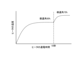
- FIG. 10 is a diagram showing an example of the relationship between heater energization time and temperature in the hand dryer according to the fourth embodiment.
- the horizontal axis indicates the energization time of the heater 23, and the vertical axis indicates the temperature of the heater 23.
- the conduction angle is gradually changed from 100% to the target set value of 50%, as described in the second embodiment.
- the microcomputer circuit 36 determines whether the hand is still inserted into the hand insertion portion 2 even after 10 seconds have elapsed since the heater 23 was turned on, that is, when the heater 23 continues to be energized.
- the set value of the conduction angle to the heater 23 is increased.
- the conduction angle to the heater 23 is changed from 50% to 75%. Note that FIG. 10 shows an example in which the set value of the conduction angle is increased for 10 seconds, but this is just an example, and any time can be set.
- FIG. 11 is a flow chart showing an example of the procedure of the heater output control method according to the fourth embodiment.
- the same step numbers are assigned to the same processes as in FIG. 5 of the first embodiment, and the description thereof is omitted.
- the microcomputer circuit 36 starts timing when heater driving is started in step S14 (step S31).
- step S16 determines whether a hand is detected in step S16 (No in step S16). If the predetermined time has not elapsed (No in step S32), the process returns to step S16. If the predetermined time has passed (Yes in step S32), the microcomputer circuit 36 increases the conduction angle to the heater 23 from the current value (step S33). After that, the microcomputer circuit 36 determines whether the hand is no longer detected by the hand detection unit 15 (step S34). If the hand is detected (No in step S34), the state of jetting the heated high-speed airflow toward the hand is continued. If the hand is no longer detected (Yes in step S34), the process proceeds to step S17.
- the angle of conduction to the heater 23 is increased, and the air at a higher speed than before the angle of conduction to the heater 23 is increased.
- the temperature of the stream can be increased to improve the feeling of warm air to the user.
- the microcomputer circuit 36 shows a method of changing the set value so that the conduction angle is determined when the hand is inserted for a predetermined period of time or longer.
- the microcomputer circuit 36 controls the conduction angle to the heater 23 so as to gradually increase to the prescribed conduction angle when the electricity supply time to the heater 23 elapses. may As a result, the feeling of warm air can be improved without causing the user to feel uncomfortable due to sudden temperature changes.
- the microcomputer circuit 36 starts timing when the heater 23 is energized, and increases the conduction angle to the heater 23 when the heater 23 is energized for a predetermined time or longer. I made it As a result, when the hands are not sufficiently dried, or when the user feels that the hands are not sufficiently dried, the feeling of warm air can be improved.
- 1 hand drying device 2 hand insertion part, 3 housing, 4 front part, 5 back part, 6 water receiving part, 7 drain tank, 10 blower part, 11 front nozzle, 12 rear nozzle, 13, 14, 17 Duct, 15 hand detection unit, 16 intake port, 18 air filter, 21 motor, 22 turbo fan, 23 heater, 30 control unit, 31 zero cross detection circuit, 32 triac, 33 DC bus power supply, 34 voltage detection circuit, 35 power supply circuit , 36 Microcomputer circuit, 40 AC power supply.
Abstract
手乾燥装置は、手挿入部を有する筐体と、手挿入部に空気流を噴射させるノズルと、空気流を発生させる送風部と、交流電源に接続され、空気流を加熱するヒータ(23)と、手挿入部へ挿入されている手を検知する手検知部と、手検知部からの手を検知したことを示す検知信号に基づいて送風部およびヒータ(23)を制御する制御部(30)と、を備える。制御部(30)は、交流電源(40)の電圧値を推定する電圧推定回路と、電圧値に応じてヒータ(23)への通電を制御する制御回路と、を有する。
Description
本開示は、濡れた手に気流を吹き付けて手を乾かす手乾燥装置に関する。
手を衛生的な状態に保全するには、洗浄後の手の乾燥処置が衛生的に行われる必要がある。洗浄後の手の衛生的な乾燥処置のために、洗浄後の濡れた手をタオルまたはハンカチで拭くことに代えて、手に高速の空気流を噴射して、手に付着している水を吹き飛ばして手を乾燥する手乾燥装置が用いられている。
手乾燥装置の手挿入部において手が検知されると、手乾燥装置は、送風部を起動して吸込口から空気を吸込み、吸込口から吸込んだ空気をヒータで加熱し、加熱された空気を手挿入部に設けられるノズルから噴射する。このとき、温度の低い風を用いる場合に比べて、ヒータで加熱された空気の流れである温風を使用することで素早く手を乾燥させることができる。
手乾燥装置のヒータの電源には交流電源が用いられる。交流電源には、100Vから120Vまでの間の交流電圧を供給する100V系の交流電源と、200Vから240Vまでの間の交流電圧を供給する200V系の交流電源と、がある。従来、手乾燥装置では、電源電圧によって異なる仕様のヒータが使い分けられている。すなわち、100V系の交流電源で使用される手乾燥装置には100V仕様のヒータが搭載され、200V系の交流電源で使用される手乾燥装置には200V仕様のヒータが搭載されている。このように交流電源の電圧値に合わせて仕様の異なる製品を用意することは、機種数の増加およびコストの増加の原因となっていた。
特許文献1には、電源電圧に関わらずモータを共通化する方法が開示されている。特許文献1では、交流電圧の電圧値を検出し、電圧値に応じて倍電圧整流および全波整流のいずれかに切り替え、同じ電圧値の直流電圧を生成して負荷に供給する構成の電源装置が開示されている。これによって、異なる電圧値の交流電源で使用される製品であっても、同じ仕様の直流負荷、すなわちモータを搭載することが可能となっている。
しかしながら、特許文献1に記載の技術は、直流で使用する負荷を共通化するものであり、交流で使用する負荷については共通化することができない。つまり、手乾燥装置におけるヒータの共通化に特許文献1に記載の技術を適用することができない。上記したように、手乾燥装置において、交流電圧が印加されるヒータは、電源電圧の種類毎に異なる仕様のものを使い分ける必要があるため、機種に関わらずヒータを共通化することが困難となる。この結果、手乾燥装置の機種数およびコストが増加してしまうという問題があった。
本開示は、上記に鑑みてなされたものであって、電源電圧の種類毎に仕様の異なるヒータを使用せずに、電源電圧の種類が異なる製品間でヒータを共通化することができる手乾燥装置を得ることを目的とする。
上述した課題を解決し、目的を達成するために、本開示の手乾燥装置は、手挿入部を有する筐体と、手挿入部に空気流を噴射させるノズルと、空気流を発生させる送風部と、交流電源に接続され、空気流を加熱するヒータと、手挿入部へ挿入されている手を検知する手検知部と、手検知部からの手を検知したことを示す検知信号に基づいて送風部およびヒータを制御する制御部と、を備える。制御部は、交流電源の電圧値を推定する電圧推定回路と、電圧値に応じてヒータへの通電を制御する制御回路と、を有する。
本開示に係る手乾燥装置は、電源電圧の種類毎に仕様の異なるヒータを使用せずに、電源電圧の種類が異なる製品間でヒータを共通化することができるという効果を奏する。
以下に、本開示の実施の形態に係る手乾燥装置を図面に基づいて詳細に説明する。
実施の形態1.
図1は、実施の形態1に係る手乾燥装置の斜視図である。図2は、実施の形態1に係る手乾燥装置の断面図であり、図1におけるII-II線に沿った断面図である。
図1は、実施の形態1に係る手乾燥装置の斜視図である。図2は、実施の形態1に係る手乾燥装置の断面図であり、図1におけるII-II線に沿った断面図である。
手乾燥装置1は、手を挿入可能とされた手挿入部2を有する筐体3を備える。手挿入部2の上部と両側部とは開放されている。手挿入部2は、上部と両側部とから手を挿入可能とされている。筐体3は、手乾燥装置1の全体の外殻をなしている。正面部4は、筐体3の一部であって、手挿入部2の正面側にある部分である。背面部5は、筐体3の一部であって、手挿入部2の背面側にある部分である。なお、正面側とは、手乾燥装置1から見て、手乾燥装置1を使用する使用者がいる側とする。背面側とは、手乾燥装置1から見て、正面側とは反対側とする。
水受け部6は、手挿入部2の最下部に位置している。水受け部6には、受けた水をドレンタンク7へ排出する図示しない排水口が設けられている。また、筐体3には、排水口からの水がドレンタンク7へ流れる図示しない排水路が設けられている。ドレンタンク7は、排水路からの水を貯留する。ドレンタンク7は、筐体3下部の正面側に設けられている。ドレンタンク7は、筐体3から取り外し可能とされている。
手乾燥装置1は、筐体3の内部で空気流を発生させる送風部10を備える。送風部10は、筐体3の内部に設けられている。送風部10は、駆動源であるDC(Direct Current)ブラシレスモータ等のモータ21と、モータ21の駆動により回転するターボファン22とを備える。送風部10の一例は、高圧空気流発生装置である。
手乾燥装置1は、手挿入部2に空気流を噴射させる正面側ノズル11および背面側ノズル12を備える。正面側ノズル11および背面側ノズル12はノズルに対応する。正面側ノズル11は、正面部4のうち手挿入部2側の面に設けられている。背面側ノズル12は、背面部5のうち手挿入部2側の面に設けられている。手乾燥装置1は、送風部10から正面部4の内部のダクト13を通過した空気流を、正面側ノズル11から手挿入部2にて噴射させる。手乾燥装置1は、送風部10から背面部5の内部のダクト14を通過した空気流を、背面側ノズル12から手挿入部2にて噴射させる。
手乾燥装置1は、手挿入部2へ挿入されている手を検知する手検知部15を備える。手検知部15は、背面部5に内蔵されている。手検知部15の一例は、測距センサである。測距センサは、赤外光を射出する発光素子と、測定対象物である手で反射した赤外光を検知する受光素子とを備える。手検知部15は、受光素子へ入射する赤外光の角度を基に、手挿入部2における手の有無を検知する。手検知部15は、手挿入部2へ挿入されている手を検知可能であればよく、測距センサ以外のセンサであってもよい。手検知部15は、正面部4に内蔵されていてもよい。
手乾燥装置1は、ダクト13,14へ送り出される空気流を加熱するヒータ23を備える。ヒータ23は、送風部10と正面側ノズル11および背面側ノズル12との間の風路に設けられる。
筐体3は、空気を吸い込む吸気口16を有する。吸気口16は、筐体3の下部に設けられている。送風部10は、吸気口16から筐体3の内部のダクト17へ空気流を取り込み、ダクト17からの空気流をダクト13,14へ送り出す。吸気口16には、ダクト17へ取り込まれる空気流から異物を取り除くエアフィルタ18が取り付けられている。
筐体3の内部には、手乾燥装置1の全体を制御する制御部30が設けられている。制御部30は、手検知部15からの手を検知したことを示す検知信号に基づいて送風部10およびヒータ23を制御する。具体的には、制御部30は、手検知部15にて手が検知されると、ヒータ23を通電させ、送風部10を駆動させる。手挿入部2から手が抜かれて、手検知部15にて手が検知されなくなると、制御部30は、ヒータ23および送風部10の動作を停止させる。
このような構成の手乾燥装置1の手挿入部2に使用者が手を挿入すると、送風部10で生成された高圧の空気流がヒータ23によって加熱され、手挿入部2の正面側壁面に設けられた正面側ノズル11および背面側壁面に設けられた背面側ノズル12に導かれる。そして、正面側ノズル11および背面側ノズル12から高速の空気流が、手挿入部2内に噴射され、手挿入部2に挿入された手に付着した水分を吹き飛ばす。そして、吹き飛ばされた水分は手挿入部2の下部の水受け部6に設けられた排水口からドレンタンク7に導かれ、ドレンタンク7に溜められる。
図3は、実施の形態1に係る手乾燥装置の制御部の回路の概略構成の一例を示す図である。なお、図3では、各回路の配置を概略的に示すものであり、実際の回路図を示すものではない。制御部30は、ゼロクロス検知回路31と、トライアック32と、直流母線電源33と、電圧検知回路34と、電源回路35と、マイクロコントローラ回路36と、を備える。以下では、マイクロコントローラ回路36は、マイコン回路36と称される。
ゼロクロス検知回路31は、交流電源40の交流電圧がゼロとなるゼロクロスを検知する回路である。トライアック32は、ヒータ23を駆動する電子部品である。図3に示されるように、ヒータ23は、トライアック32と直列に接続される。また、ヒータ23は、交流電源40に接続される。ここでは、交流電源40の電圧によって手乾燥装置1の仕様、すなわち種類が異なるが、ヒータ23は、交流電源40の電圧に依らず、すなわち手乾燥装置1の種類に依らず、同一種類のものが用いられる。
直流母線電源33は、交流電源40から供給される電源を整流し、平滑して直流母線電圧を生成する。直流母線電源33は、交流電源40の電圧の実効値に対応した直流母線電圧を生成する。交流電源40の電圧の実効値は、交流電源40の電圧値とも称される。電圧検知回路34は、直流母線電圧の電圧値を検知する。電圧検知回路34は、直流母線電圧の電圧値を検知するものであるが、直流母線電源33の電圧値と交流電源40の電圧値とが対応付けられる場合には、直流母線電圧の電圧値から交流電源40の電圧値を推定することができる。電圧検知回路34は、交流電源40の電圧値を検知または推定することができるものであればよい。電圧検知回路34は、電圧推定回路に対応する。電源回路35は、直流母線電圧からモータ21を駆動する交流電力を生成する回路である。電源回路35にモータ21が接続される。電源回路35の一例は、インバータ回路である。
マイコン回路36は、交流電源40の電圧値に応じて、ヒータ23への通電を制御する。具体的には、マイコン回路36は、交流電源40の電圧値に応じて、ヒータ23への通電に関する設定であるヒータ制御設定を行う。ヒータ制御設定は、一例では手乾燥装置1の電源がオンにされた場合に実行される。ここでは、マイコン回路36は、電圧検知回路34によって検知された直流母線電源33の電圧である電圧検知値を手乾燥装置1に供給される交流電源40の電圧値とする。マイコン回路36は、定められた期間における、交流電源40の電圧値の大きさに応じたヒータ23への通電の期間の割合である通電割合を決定する。この通電割合は、ヒータ通電割合に対応する。定められた期間は、交流電源40の電圧の1周期とすることができる。決定された通電割合となるように、トライアック32のゲートへのオン指令のタイミングが設定される。この通電割合、すなわちオン指令のタイミングの設定がヒータ制御設定となる。マイコン回路36は、検知または推定された電圧値が定められた基準値よりも大きい場合には、検知または推定された電圧値が基準値よりも小さい場合に比して、通電割合を小さくする。
マイコン回路36は、手検知部15からの情報、ヒータ制御設定およびゼロクロス検知回路31からの情報を基にトライアック32およびモータ21に接続される電源回路35を制御する。これによって、手挿入部2に手が挿入されている間における手挿入部2への温風の噴出が制御される。なお、図示されていないが、マイコン回路36は、図1に示される手検知部15とも電気的に接続され、手検知部15からの情報によって手挿入部2に手が存在しているか、手が存在しないか、を判定する。マイコン回路36は、制御回路に対応する。
ヒータ23およびトライアック32は、交流電源40と直流母線電源33との間に接続されている。ゼロクロス検知回路31は、交流電源40と、ヒータ23およびトライアック32と、の間に接続される。電圧検知回路34は、直流母線電源33の出力側に接続される。
マイコン回路36は、ヒータ制御設定およびゼロクロス検知回路31からの情報を基にオン指令またはオフ指令を生成し、トライアック32の図示しないゲートに出力する。トライアック32は、マイコン回路36からのオン指令またはオフ指令に基づいてオンまたはオフされる。この例では、ヒータ23は、位相制御にて駆動される構成となっている。図4は、位相制御の動作原理を説明するための図である。図4には、入力電圧波形VIと、トライアック32のゲートに入力される信号であるゲート入力信号GIと、ヒータ23に印加される電圧波形VHと、が示されている。これらの図において、横軸は時刻を示している。また、入力電圧波形VIおよびヒータ23に印加される電圧波形VHにおける縦軸は電圧を示し、ゲート入力信号GIにおける縦軸は信号のオンまたはオフを示している。なお、ここでは、トライアック32をオフにするタイミングを、入力電圧波形VIがゼロとなる場合としており、このタイミングでトライアック32に流れる電流はゼロとなる。このため、マイコン回路36は、オフ指令を出力しないものとしている。すなわち、ゲート入力信号GIは、マイコン回路36から出力されるオン指令GI1,GI2,GI3を示している。
位相制御は、トライアック32によって交流電圧を直接オンまたはオフして印加電圧を可変する制御方式であり、電源ゼロクロスポイントを基準にしてオン時間およびオフ時間のタイミングを調整してヒータ23への印加電圧を変化させる。電源ゼロクロスポイントは、入力電圧波形VIにおいて、電圧がゼロとなる点である。
具体的には、マイコン回路36は、トライアック32へのオン指令GI1,GI2,GI3を、入力電圧波形VIの半周期毎に出力する。図4の例では、マイコン回路36は、時刻t1,t3,t5でオン指令GI1,GI2,GI3を出力する。時刻t1でマイコン回路36からトライアック32のゲートへのオン指令GI1が出力されると、時刻t1でトライアック32がオンされ、トライアック32およびヒータ23に電流が流れる。その後、入力電圧がゼロになる時刻t2で、トライアック32はオフとなり、ヒータ23に電流が流れなくなる。ヒータ23には、図4のヒータ23に印加される電圧波形VHのように電圧が印加される。つまり、入力電圧波形VIの時刻t0から時刻t2までの半周期のうち、時刻t1から時刻t2までの時間に、ヒータ23に電圧が印加され、時刻t0から時刻t1までの時間には、ヒータ23には電圧は印加されない。
その後、時刻t3でマイコン回路36からトライアック32のゲートへのオン指令GI2が出力されると、時刻t3でトライアック32がオンされ、トライアック32およびヒータ23に電流が流れる。このときのトライアック32およびヒータ23に流れる電流の向きは、時刻t1からt2の間に流れる電流の向きとは逆向きとなる。その後、入力電圧がゼロになる時刻t4で、トライアック32はオフとなり、ヒータ23に電流が流れなくなる。ヒータ23には、図4のヒータ23に印加される電圧波形のように電圧が印加される。つまり、入力電圧波形VIの時刻t2から時刻t4までの半周期のうち、時刻t3から時刻t4までの時間に、ヒータ23に電圧が印加され、時刻t2から時刻t3までの時間には、ヒータ23には電圧は印加されない。そして、このような処理が繰り返し行われることになる。ゲートへのオン指令GI1,GI2,GI3の出力タイミング、すなわちオン時間を調整することで、ヒータ23への印加電圧を変化させることが可能となる。
例えば、入力電圧波形VIにおいて電圧がゼロになる電源ゼロクロスポイントでオンするように、マイコン回路36が時刻t0,t2,t4でトライアック32のゲートにオン指令GI1,GI2,GI3を出力した場合には、ヒータ23への導通角は100%となる。また、入力電圧波形VIの1周期を360度として、電源ゼロクロスポイントから90度進んだ位置でトライアック32のゲートにオン指令GI1,GI2,GI3を出力した場合はヒータ23への導通角は50%となる。つまり、定められた期間である1周期の期間におけるヒータ23への通電の期間の割合である通電割合が、導通角となる。1周期の内、トライアック32がオンの時間すなわちヒータ23への通電時間が長ければ電力値は大きくなり、オン時間が短ければ電力値は小さくなる。オンおよびオフのタイミング、すなわち導通角はマイコン回路36によって任意に設定することができる。
このように、マイコン回路36がトライアック32のゲートへオン指令GI1,GI2,GI3を出力するタイミングで、ヒータ23に印加される電圧が変化するので、ヒータ23で発生する熱量も変化する。交流電源40の種類に応じて、トライアック32のゲートへのオン指令GI1,GI2,GI3の出力タイミングを調整することで、ヒータ23で発生する熱量が交流電源40の種類に依らず定められた量とすることができる。このために、マイコン回路36は、電圧検知回路34から直流母線電源33の出力電圧を取得し、出力電圧から交流電源40の電圧値を推定する。また、マイコン回路36は、ゼロクロス検知回路31からの情報を取得する。ゼロクロス検知回路31からの情報は、一例では、ゼロクロス検知回路31がゼロクロスを検知した時刻である電源ゼロクロスポイントを含む。マイコン回路36は、電源ゼロクロスポイントを基準にして、出力電圧の値に応じた導通角となるように、トライアック32のゲートへのオン指令GI1,GI2,GI3の出力タイミングを決定する。
なお、ここでは、位相制御を用いてヒータ23への通電割合を制御する例を示したが、通電率制御を用いてヒータ23への通電割合を制御してもよい。
次に、この実施の形態1に係る手乾燥装置1の制御部30による制御方法について説明する。図5は、実施の形態1に係る手乾燥装置の制御方法の手順の一例を示すフローチャートである。ここでは、交流電源40の電圧値が100Vから200Vまでの間の交流電圧を供給する100V系の交流電源、および200Vから240Vまでの間の交流電圧を供給する200V系の交流電源のいずれかであるものとする。
まず、手乾燥装置1の電源がオンされると、電圧検知回路34は、直流母線電源33の電圧を検知し、検知結果である電圧検知値をマイコン回路36に出力する(ステップS11)。直流母線電源33の電圧値は、交流電源40の電圧値に応じて変化するので、直流母線電源33の電圧検知値によって交流電源40の電圧値を推定することが可能となる。
マイコン回路36は、電圧検知回路34から電圧検知値を受信すると、ヒータ制御設定を行う(ステップS12)。ヒータ制御設定は、上記したように、導通角の設定であり、トライアック32のゲートへのオン指令の出力タイミングの設定である。一例では、マイコン回路36は、電圧検知値と導通角とを対応付けたヒータ制御設定情報を保持しており、電圧検知値に対応する導通角をヒータ制御設定情報から取得し、導通角に基づいて設定を行う。
図6は、ヒータ制御設定情報の一例を示す図である。ヒータ制御設定情報は、直流母線電源33の電圧検知値と、導通角と、が対応付けられている。ここでは、電圧検知値の範囲と導通角とが対応付けられている。具体的には、直流母線電源33の電圧検知値が150V以下の場合には、導通角が100%とされ、電圧検知値が150Vよりも大きい場合には、導通角が50%とされる。電圧検知値が150V以下の場合は、交流電源40が100V系の交流電源である場合であり、電圧検知値が150Vよりも大きい場合は、交流電源40が200V系の交流電源である場合である。このように、交流電源40の電圧値が小さいほど、導通角、すなわち通電割合を大きくするように設定される。
なお、直流母線電源33の電圧検知値が150Vの場合には、図6では導通角が100%とされているが、導通角が50%とされてもよい。また、ヒータ制御設定情報で150Vは、導通角の設定を分ける基準となる値であり、基準値に対応する。ここでの基準値は150Vであるが、これは、一例であり、他の値でもよい。また、図6の導通角も一例であり、任意の値とすることができる。ただし、交流電源40の電圧値が低いほど、導通角が大きくなるように設定される。
マイコン回路36は、電圧検知値が150V以下の場合は100V系の交流電源に対応した機種である、すなわち100Vの交流電源に接続されていると判定し、ヒータ制御設定情報を参照して導通角を100%に設定する。また、マイコン回路36は、電圧検知値が150Vよりも大きい場合には200V系の交流電源に対応した機種である、すなわち200Vの交流電源に接続されていると判定し、ヒータ制御設定情報を参照して導通角を50%に設定する。
図5に戻り、マイコン回路36は、手検知部15によって手が検知されたかを判定する(ステップS13)。手が検知されない場合(ステップS13でNoの場合)には、待ち状態となる。手が検知された場合(ステップS13でYesの場合)、すなわち手挿入部2へ使用者の手が挿入された場合には、マイコン回路36は、ステップS12で設定されたヒータ制御設定に従ってヒータ駆動を開始する(ステップS14)。すなわち、マイコン回路36は、ヒータ23への通電制御を開始する。具体的には、マイコン回路36は、ゼロクロス検知回路31から電源ゼロクロスポイントを検知したことを示す情報を受けると、検知信号を受けてから導通角に対応する時間の経過後に、オン指令をトライアック32のゲートに出力する。トライアック32のゲートにオン指令が入力されると、トライアック32は通電状態となり、ヒータ23に電圧が印加される。その後、交流電源40からの入力電圧がゼロになると、トライアック32に流れる電流はゼロとなり、ヒータ23に印加される電圧はゼロとなる。このとき、ゼロクロス検知回路31は、電源ゼロクロスポイントを検知し、マイコン回路36に検知信号を通知する。このように、オン指令を受けてから入力電圧がゼロになるまでの間、ヒータ23に電圧が印加される処理が繰り返し実行される。
また、マイコン回路36は、モータ駆動を開始する(ステップS15)。ここでは、マイコン回路36は、モータ21への導通角が定められた値となるように制御する。これによって、送風部10で生成され、ヒータ23によって加熱された高圧の空気流が、手挿入部2の正面側ノズル11および背面側ノズル12から高速の空気流として、手に向かって噴射される。
その後、マイコン回路36は、手検知部15によって手が検知されなくなったかを判定する(ステップS16)。手が検知されている場合(ステップS16でNoの場合)には、加熱された高速の空気流を手に向かって噴射する状態が継続される。また、手が検知されなくなった場合(ステップS16でYesの場合)、すなわち手挿入部2から手が取り出された場合には、マイコン回路36は、ヒータ駆動を停止し(ステップS17)、マイコン回路36は、モータ駆動を停止する(ステップS18)。そして、処理がステップS13へと戻る。
以上のように、実施の形態1では、交流電源40における電源ゼロクロスポイントを検知するゼロクロス検知回路31と、交流電源40を直流電源に変換する直流母線電源33の電圧値を検知する電圧検知回路34と、ヒータ23に直列に接続されるトライアック32と、電圧検知回路34での電圧検知値に応じてヒータ23に印加する電圧を制御するマイコン回路36と、を備える。マイコン回路36は、電圧検知値の大きさに応じてヒータ23への導通角を設定する。電圧検知値が大きいときには、電圧検知値が小さいときに比して、導通角が小さくなるように、導通角は設定される。マイコン回路36は、手挿入部2に手が挿入された場合にヒータ23を駆動する。このとき、マイコン回路36は、ゼロクロス検知回路31からゼロクロスを検知したことを示す情報を受けると、設定された導通角に対応する時間が経過した後に、トライアック32にオン指令を出力し、ヒータ23に交流電圧を印加する。そして、交流電圧がゼロになると、ヒータ23に印加される交流電圧がゼロとなる。このように、交流電圧の周期のうち設定された導通角に対応する期間に、ヒータ23に交流電圧を印加することができる。つまり、交流電源40の電圧値に対応して、空気流が目標温度となるようにヒータ23に交流電圧を印加することができる。
電圧検知値が低い場合、一例では手乾燥装置1が、100V系の交流電源に対応した機種である場合、すなわち100V系の交流電源に接続されている場合には、ヒータ23への導通角が大きく設定される。電圧検知値が高い場合、一例では手乾燥装置1が、200V系の交流電源に対応した機種である場合、すなわち200V系の交流電源に接続されている場合には、ヒータ23への導通角が小さく設定される。これによって、交流電源40の電圧値が異なっていても、共通のヒータ23における加熱性能を同等に維持することができる。つまり、交流電源40の種類に応じた手乾燥装置1の機種間において、ヒータ23を共通化することができる。この結果、交流電源40の電源電圧毎に仕様の異なるヒータ23を使用せずに、交流電源40の電源電圧が異なる製品間でヒータ23を共通化することができるという効果を有する。
また上記した図5の説明では、100V系の交流電源に対応した機種と200V系の交流電源に対応した機種との場合について、ヒータ制御設定を変える例を示した。しかし、向け先によっては、110Vの交流電源、120Vの交流電源、220Vから240Vまでの交流電源の3種類の交流電源40が提供される地域もある。この場合には、導通角の設定を行う際に、電圧毎に場合分けすればよい。すなわち、ヒータ制御設定で、110Vの交流電源、120Vの交流電源、220Vから240Vまでの交流電源のそれぞれについて、電圧検知値の範囲と導通角とを定めればよい。これによって、電源電圧をさらに細分化してヒータ23への導通角を設定することが可能となる。
実施の形態2.
実施の形態1では、電圧検知回路34で検知された電圧検知値に対してヒータ23への導通角を設定すると、その後のヒータ23の駆動時において、導通角は一定としていた。実施の形態2では、ヒータ23の駆動時において、導通角を変化させる場合を示す。
実施の形態1では、電圧検知回路34で検知された電圧検知値に対してヒータ23への導通角を設定すると、その後のヒータ23の駆動時において、導通角は一定としていた。実施の形態2では、ヒータ23の駆動時において、導通角を変化させる場合を示す。
実施の形態2に係る手乾燥装置1の構成は、実施の形態1で示したものと同様であるが、制御部30におけるマイコン回路36の機能が実施の形態1とは異なる。以下では、実施の形態1と異なる点について説明する。実施の形態2では、マイコン回路36は、交流電源40の電圧値の大きさに対して設定されるヒータ23への通電割合である導通角を目標の導通角とし、目標の導通角よりも大きな導通角でヒータ23への通電を開始し、定められた時間の経過後に目標の導通角に変更する。つまり、ヒータ制御設定情報における導通角は、目標の設定値となる。そして、マイコン回路36は、ヒータ23の駆動開始時は導通角を目標の設定値よりも大きくし、目標の設定値まで徐々に小さくしていく。導通角を変えるタイミング、時間等は任意に設定することができる。
図7は、実施の形態2に係る手乾燥装置におけるヒータの通電時間と温度との関係の一例を示す図である。この図で、横軸はヒータ23の通電時間を示し、縦軸はヒータ23の温度を示している。実線で表記されているグラフG1は、実施の形態1における200V系の交流電源に対応した機種における、導通角を50%に設定したときの目標温度に到達するまでの通電時間と温度との関係を示している。破線で表記されているグラフG2は、200V系の交流電源に対応した機種における、導通角を目標の設定値まで徐々に小さくしていったときの目標温度に到達するまでの通電時間と温度との関係を示している。グラフG2では、導通角の目標の設定値は、50%であるが、導通角を100%→90%→80%→・・・→50%のように変化させている。
グラフG2の場合、マイコン回路36は、ヒータ駆動を開始すると、導通角が100%に設定されている状態であるので、ゼロクロス検知回路31からゼロクロスを検知したことを示す情報を受けたときに、トライアック32のゲートにオン指令を出力する。マイコン回路36は、このオン指令を定められた回数または時間実施した後、導通角を90%に設定する。マイコン回路36は、ゼロクロス検知回路31からゼロクロスを検知したことを示す情報を受けてから、導通角が90%に対応する時間だけ経過した後に、トライアック32のゲートにオン指令を出力する。マイコン回路36は、このオン指令を定められた回数または時間実施した後、導通角が50%となるまで導通角を10ポイントずつ低下させて同様の処理を行う。
グラフG1に示されるように、導通角を変化させずに一定として制御すると、ヒータ23の温度は通電時間とともに徐々に上昇し、目標温度に到達する。これに対して、グラフG2に示されるように、通電開始時に目標の設定値よりも大きく導通角を設定し、目標の設定値まで徐々に小さくすることで、立ち上がりで急激に温度が上昇する。このため、速く目標温度に到達させることが可能となる。
実施の形態2では、マイコン回路36は、ヒータ23への通電を開始すると、導通角が大きい値から、目標の設定値まで徐々に導通角を小さくするようにした。これによって、100%よりも低い導通角が目標の設定値となる場合に、目標の設定値で導通角を設定してヒータ23への通電を開始した場合に比して、目標温度までの到達時間を短縮することができる。つまり、実施の形態1では、ヒータ23が温まるまでに時間を要してしまうが、実施の形態2の方式では、ヒータ23の温度を実施の形態1に比して速く目標温度に到達させることができる。このため、使用者の手をより速く乾かすことが可能となる。
また、上記した説明では、目標の設定値まで導通角を徐々に小さくしていく方法を説明した。導通角を小さくするステップの数は、1回以上であればよい。一例では、目標の設定値よりも大きな導通角でヒータ23への通電を定められた時間実施した後に、目標の設定値に変更してもよい。
さらに、上記した例は、100V系の交流電源に対応する機種用のヒータ23を手乾燥装置1に使用した場合で、200V系の交流電源がヒータ23に印加される場合に有効である。しかし、ヒータ23の発熱がさらに高いものを選定することによって、100V系の交流電源の印加時でも加熱時間を短縮させる効果を期待することができる。
実施の形態3.
実施の形態1では、マイコン回路36は、モータ21への導通角を定められた一定の値となるようにモータ21を駆動する場合を示した。実施の形態3では、ヒータ23とともにモータ21への導通角も変化させる場合を示す。
実施の形態1では、マイコン回路36は、モータ21への導通角を定められた一定の値となるようにモータ21を駆動する場合を示した。実施の形態3では、ヒータ23とともにモータ21への導通角も変化させる場合を示す。
実施の形態3に係る手乾燥装置1の構成は、実施の形態1,2で示したものと同様であるが、制御部30におけるマイコン回路36の機能が実施の形態1,2とは異なる。以下では、実施の形態1,2と異なる点について説明する。また、以下では、手乾燥装置1が実施の形態2の構成を有するものとして説明する。
実施の形態3では、マイコン回路36は、ヒータ23への通電割合である導通角の変更に応じて、定められた期間におけるモータ21への通電の期間の割合であるモータ21への導通角を徐々に大きくする。モータ21への導通角は、モータ通電割合に対応する。つまり、マイコン回路36は、目標の設定値に向かってヒータ23への導通角を徐々に小さくするのに応じて、モータ21への導通角を徐々に大きくしていく。
図8は、実施の形態2に係る手乾燥装置における通電時間と消費電力との関係の一例を示す図である。この図において、横軸は通電時間を示し、縦軸は消費電力を示す。実線で表記されているグラフG11は、導通角一定としてモータ21を駆動したときの消費電力を示し、破線で表記されているグラフG12は、ヒータ23への導通角を徐々に小さくしたときの消費電力を示している。一点鎖線で表記されているグラフG13は、モータ21の消費電力とヒータ23の消費電力とを合成した負荷全体の消費電力を示している。グラフG12に示されるように、ヒータ23への通電の直後は、ヒータ23への導通角が大きいため、ヒータ23で消費される電力は、通電時間中で最大となる。この結果、モータ21およびヒータ23の消費電力を合成した負荷全体の消費電力は、グラフG13に示されるように、通電開始時に大きな電力値となっている。
図9は、実施の形態3に係る手乾燥装置における通電時間と消費電力との関係の一例を示す図である。この図において、横軸は通電時間を示し、縦軸は消費電力を示す。実線で表記されているグラフG21は、モータ21への導通角を徐々に大きくしたときの消費電力を示し、破線で表記されているグラフG22は、ヒータ23への導通角を徐々に小さくしたときの消費電力を示している。一点鎖線で表記されているグラフG23は、モータ21の消費電力とヒータ23の消費電力とを合成した負荷全体の消費電力を示している。図9でも、グラフG22に示されるように、ヒータ23への通電の直後は、ヒータ23への導通角が大きいため、ヒータ23で消費される電力は、通電時間中で最大となる。一方、実施の形態3では、グラフG21に示されるように、ヒータ23への導通角が徐々に小さくなるのに応じてモータ21への導通角を徐々に大きくしている。このように制御することで、グラフG23に示されるように、負荷全体の消費電力を常に一定に保つことができる。また、図8の場合に比して、消費電力を抑制することができ、省エネルギ性を高めることができる。
実施の形態3では、手乾燥装置1のマイコン回路36が、ヒータ23への通電を開始すると、ヒータ23への導通角については、目標の設定値よりも大きい値から目標の設定値まで徐々に下げるようにし、モータ21への導通角については、定められた値よりも小さい値から定められた値まで徐々に上げるようにした。これによって、ヒータ23の目標温度到達時間を実施の形態2の場合と同様となるように維持しながら、負荷全体の消費電力を一定に保つことができる。この結果、温風感を損なうことなく省エネルギ性を向上させることができる。
また、図8に示される制御では、起動時すなわち通電開始時に大きな突入電流が流れ、電流ヒューズが早切れしたり、電源系の電子部品が劣化したりして早期故障につながる可能性がある。しかし、実施の形態3の図9に示される制御では、起動時の突入電流を抑えることができるため、電源系の電子部品が故障する可能性を低減することができる。
上記した説明では、モータ21への導通角を制御することを説明したが、モータ21への導通角を、位相制御、通電率制御、インバータ制御等を用いて制御してもよい。
実施の形態4.
実施の形態1では、電圧検知回路34で検知された電圧検知値に対して導通角を設定すると、その後のヒータ23の駆動時において、導通角は一定としていた。また、実施の形態2では、ヒータ23の駆動時において、目標の設定値となるように、導通角を徐々に小さく変化させていた。実施の形態4では、定められた期間よりも長くヒータ23への通電が行われた場合に、ヒータ23への導通角を大きくする場合を示す。
実施の形態1では、電圧検知回路34で検知された電圧検知値に対して導通角を設定すると、その後のヒータ23の駆動時において、導通角は一定としていた。また、実施の形態2では、ヒータ23の駆動時において、目標の設定値となるように、導通角を徐々に小さく変化させていた。実施の形態4では、定められた期間よりも長くヒータ23への通電が行われた場合に、ヒータ23への導通角を大きくする場合を示す。
実施の形態4に係る手乾燥装置1の構成は、実施の形態1から3で示したものと同様であるが、制御部30におけるマイコン回路36の機能が実施の形態1から3とは異なる。以下では、実施の形態1から3と異なる点について説明する。また、以下では、手乾燥装置1が実施の形態2の構成を有するものとして説明する。実施の形態4では、マイコン回路36は、ヒータ23への通電の開始から計時を行い、ヒータ23への通電時間が定められた時間を経過して、ヒータ23への通電が継続された場合に、ヒータ23への導通角を大きくする。
手を洗った後の手の乾燥時間は、季節または手の洗い方によって違いが出てくることがある。また、使用者によって、手が十分に乾燥したとの認識には個人差がある。一定時間経過しても手の乾燥が十分に行えていない場合、あるいは使用者が手の乾燥が十分に行えていないと感じている場合には、手乾燥装置1の使用時間が長くなる。そこで、マイコン回路36は、手の乾燥が定められた時間経過しても継続されている場合には、乾燥が不十分であると判断し、ヒータ23の温度をさらに上昇させる。つまり、ヒータ23への導通角を目標の設定値よりも上げる。これによって、使用者の温風感を向上させ、乾燥にかかる時間を短くする。
図10は、実施の形態4に係る手乾燥装置におけるヒータの通電時間と温度との関係の一例を示す図である。この図で、横軸はヒータ23の通電時間を示し、縦軸はヒータ23の温度を示している。ヒータ23の通電時間が10秒までは、実施の形態2で説明したように、導通角を100%から目標の設定値である50%まで徐々に変化させている。マイコン回路36は、ヒータ23の通電の開始から10秒が経過しても、手が手挿入部2に挿入されている状態が継続している場合、すなわちヒータ23への通電が継続される場合には、ヒータ23への導通角の設定値を大きくする。図10の例では、ヒータ23への導通角が50%から75%に変更されている。なお、図10では、導通角の設定値を大きくする時間が10秒である例が示されているが、これは一例であり、任意の時間とすることができる。
次に、この実施の形態4に係る手乾燥装置1の制御部30による制御方法について説明する。図11は、実施の形態4に係るヒータの出力制御方法の手順の一例を示すフローチャートである。なお、実施の形態1の図5と同じ処理には同じステップ番号を付して、その説明を省略する。
実施の形態4では、マイコン回路36は、ステップS14でヒータ駆動を開始すると、計時を開始する(ステップS31)。
また、ステップS16で手が検知されている場合(ステップS16でNoの場合)には、ヒータ駆動の開始から定められた時間が経過したかを判定する(ステップS32)。定められた時間が経過していない場合(ステップS32でNoの場合)には、処理がステップS16に戻る。定められた時間が経過している場合(ステップS32でYesの場合)には、マイコン回路36は、ヒータ23への導通角を現在の値よりも増加させる(ステップS33)。その後、マイコン回路36は、手検知部15によって手が検知されなくなったかを判定する(ステップS34)。手が検知されている場合(ステップS34でNoの場合)には、加熱された高速の空気流を手に向かって噴射する状態が継続される。手が検知されなくなった場合(ステップS34でYesの場合)には、処理がステップS17に移る。
このような処理によって、使用者が定められた時間以上、手を挿入している場合に、ヒータ23への導通角を大きくして、ヒータ23への導通角を大きくする前よりも高速の空気流の温度を高め、使用者への温風感を向上させることができる。
上記した説明では、マイコン回路36は、定められた時間以上、手が挿入されている場合に、定められた導通角となるように設定値を変更する方法を示した。しかし、マイコン回路36は、ヒータ23への通電時間が定められた時間を経過した場合に、ヒータ23への導通角を、定められた導通角となるように、徐々に大きくするように制御してもよい。これにより、急激な温度変化により使用者が不快を感じることなく、温風感を向上させることができる。
また、上記した説明では、実施の形態2の手乾燥装置1に実施の形態4を適用する場合を説明したが、実施の形態1,3の手乾燥装置1に実施の形態4を適用してもよい。
実施の形態4では、マイコン回路36は、ヒータ23への通電を開始すると、計時を開始し、定められた時間以上、ヒータ23が通電されている場合に、ヒータ23への導通角を増加させるようにした。これによって、手の乾燥が十分に行えていない場合、あるいは使用者が手の乾燥が十分に行えていないと感じている場合に、温風感を向上させることができるという効果を有する。
以上の実施の形態に示した構成は、一例を示すものであり、別の公知の技術と組み合わせることも可能であるし、実施の形態同士を組み合わせることも可能であるし、要旨を逸脱しない範囲で、構成の一部を省略、変更することも可能である。
1 手乾燥装置、2 手挿入部、3 筐体、4 正面部、5 背面部、6 水受け部、7 ドレンタンク、10 送風部、11 正面側ノズル、12 背面側ノズル、13,14,17 ダクト、15 手検知部、16 吸気口、18 エアフィルタ、21 モータ、22 ターボファン、23 ヒータ、30 制御部、31 ゼロクロス検知回路、32 トライアック、33 直流母線電源、34 電圧検知回路、35 電源回路、36 マイコン回路、40 交流電源。
Claims (9)
- 手挿入部を有する筐体と、
前記手挿入部に空気流を噴射させるノズルと、
前記空気流を発生させる送風部と、
交流電源に接続され、前記空気流を加熱するヒータと、
前記手挿入部へ挿入されている手を検知する手検知部と、
前記手検知部からの前記手を検知したことを示す検知信号に基づいて前記送風部および前記ヒータを制御する制御部と、
を備え、
前記制御部は、
前記交流電源の電圧値を推定する電圧推定回路と、
前記電圧値に応じて前記ヒータへの通電を制御する制御回路と、
を有することを特徴とする手乾燥装置。 - 前記制御回路は、推定された前記電圧値が定められた基準値よりも大きい場合には、推定された前記電圧値が前記基準値よりも小さい場合に比して、定められた期間における前記ヒータへの通電の期間の割合であるヒータ通電割合を小さくすることを特徴とする請求項1に記載の手乾燥装置。
- 前記制御回路は、位相制御によって前記ヒータ通電割合を制御することを特徴とする請求項2に記載の手乾燥装置。
- 前記制御回路は、通電率制御によって前記ヒータ通電割合を制御することを特徴とする請求項2に記載の手乾燥装置。
- 前記制御回路は、前記交流電源の電圧値の大きさに対して設定される定められた期間における前記ヒータへの通電の期間の割合であるヒータ通電割合を目標のヒータ通電割合とし、前記目標のヒータ通電割合よりも大きなヒータ通電割合で前記ヒータへの通電を開始し、定められた時間の経過後に前記目標のヒータ通電割合に変更することを特徴とする請求項1から4のいずれか1つに記載の手乾燥装置。
- 前記制御回路は、前記ヒータへの通電の開始から前記目標のヒータ通電割合まで、徐々に前記ヒータ通電割合を小さくすることを特徴とする請求項5に記載の手乾燥装置。
- 前記送風部は、回転することによって前記空気流を発生させるファンと、前記ファンを回転させるモータと、を有し、
前記制御回路は、前記ヒータ通電割合の変更に応じて、定められた期間における前記モータへの通電の期間の割合であるモータ通電割合を徐々に大きくすることを特徴とする請求項5または6に記載の手乾燥装置。 - 前記制御回路は、前記ヒータへの通電時間が定められた時間を経過した場合に、定められた期間における前記ヒータへの通電の期間の割合であるヒータ通電割合を大きくすることを特徴とする請求項1から7のいずれか1つに記載の手乾燥装置。
- 前記制御回路は、前記ヒータへの通電時間が定められた時間を経過した場合に、定められた期間における前記ヒータへの通電の期間の割合であるヒータ通電割合を徐々に大きくすることを特徴とする請求項1から7のいずれか1つに記載の手乾燥装置。
Priority Applications (2)
| Application Number | Priority Date | Filing Date | Title |
|---|---|---|---|
| PCT/JP2021/045484 WO2023105743A1 (ja) | 2021-12-10 | 2021-12-10 | 手乾燥装置 |
| JP2023565832A JPWO2023105743A1 (ja) | 2021-12-10 | 2021-12-10 |
Applications Claiming Priority (1)
| Application Number | Priority Date | Filing Date | Title |
|---|---|---|---|
| PCT/JP2021/045484 WO2023105743A1 (ja) | 2021-12-10 | 2021-12-10 | 手乾燥装置 |
Publications (1)
| Publication Number | Publication Date |
|---|---|
| WO2023105743A1 true WO2023105743A1 (ja) | 2023-06-15 |
Family
ID=86729970
Family Applications (1)
| Application Number | Title | Priority Date | Filing Date |
|---|---|---|---|
| PCT/JP2021/045484 WO2023105743A1 (ja) | 2021-12-10 | 2021-12-10 | 手乾燥装置 |
Country Status (2)
| Country | Link |
|---|---|
| JP (1) | JPWO2023105743A1 (ja) |
| WO (1) | WO2023105743A1 (ja) |
Citations (5)
| Publication number | Priority date | Publication date | Assignee | Title |
|---|---|---|---|---|
| JP2000316280A (ja) * | 1999-04-27 | 2000-11-14 | Sony Corp | 電源装置 |
| JP2001327433A (ja) * | 2000-05-25 | 2001-11-27 | Matsushita Electric Ind Co Ltd | 手乾燥装置 |
| JP2006097924A (ja) * | 2004-09-28 | 2006-04-13 | Matsushita Electric Ind Co Ltd | 換気装置 |
| JP2007117243A (ja) * | 2005-10-26 | 2007-05-17 | Matsushita Electric Ind Co Ltd | 暖房便座 |
| WO2015128988A1 (ja) * | 2014-02-27 | 2015-09-03 | 三菱電機株式会社 | 手乾燥装置 |
-
2021
- 2021-12-10 WO PCT/JP2021/045484 patent/WO2023105743A1/ja active Application Filing
- 2021-12-10 JP JP2023565832A patent/JPWO2023105743A1/ja active Pending
Patent Citations (5)
| Publication number | Priority date | Publication date | Assignee | Title |
|---|---|---|---|---|
| JP2000316280A (ja) * | 1999-04-27 | 2000-11-14 | Sony Corp | 電源装置 |
| JP2001327433A (ja) * | 2000-05-25 | 2001-11-27 | Matsushita Electric Ind Co Ltd | 手乾燥装置 |
| JP2006097924A (ja) * | 2004-09-28 | 2006-04-13 | Matsushita Electric Ind Co Ltd | 換気装置 |
| JP2007117243A (ja) * | 2005-10-26 | 2007-05-17 | Matsushita Electric Ind Co Ltd | 暖房便座 |
| WO2015128988A1 (ja) * | 2014-02-27 | 2015-09-03 | 三菱電機株式会社 | 手乾燥装置 |
Also Published As
| Publication number | Publication date |
|---|---|
| JPWO2023105743A1 (ja) | 2023-06-15 |
Similar Documents
| Publication | Publication Date | Title |
|---|---|---|
| JP2011019606A (ja) | 手乾燥装置 | |
| RU2006123537A (ru) | Стиральная машина и способ управления ею | |
| JP6496902B2 (ja) | 浴室換気乾燥機 | |
| KR20210117879A (ko) | 건조장치 | |
| WO2023105743A1 (ja) | 手乾燥装置 | |
| JP2001346715A (ja) | 手乾燥装置 | |
| JP2019000422A (ja) | 便座装置 | |
| EP3881743A1 (en) | Drying apparatus and related methods | |
| JP5953883B2 (ja) | 浴室衣類乾燥装置 | |
| JP4792794B2 (ja) | 手乾燥装置 | |
| JP6056007B2 (ja) | 浴室暖房乾燥機 | |
| TWI622374B (zh) | Hand dryer | |
| JP6103468B2 (ja) | 手乾燥装置 | |
| JP5127952B2 (ja) | 手乾燥装置 | |
| JP2004283209A (ja) | 食器乾燥機 | |
| JP2783078B2 (ja) | 手乾燥装置 | |
| JP4771993B2 (ja) | 手乾燥装置 | |
| JP6202463B2 (ja) | 手乾燥装置 | |
| JP7309082B2 (ja) | 手乾燥装置 | |
| JP6682918B2 (ja) | 手乾燥装置 | |
| WO2020161866A1 (ja) | 手乾燥装置 | |
| JP2017056032A (ja) | 手乾燥装置 | |
| JP6464959B2 (ja) | 浴室乾燥装置 | |
| WO2018189788A1 (ja) | 手乾燥装置 | |
| JP6221052B2 (ja) | 手乾燥装置 |
Legal Events
| Date | Code | Title | Description |
|---|---|---|---|
| 121 | Ep: the epo has been informed by wipo that ep was designated in this application |
Ref document number: 21967237 Country of ref document: EP Kind code of ref document: A1 |
|
| WWE | Wipo information: entry into national phase |
Ref document number: 2023565832 Country of ref document: JP |