WO2023074105A1 - ツール交換装置 - Google Patents
ツール交換装置 Download PDFInfo
- Publication number
- WO2023074105A1 WO2023074105A1 PCT/JP2022/032196 JP2022032196W WO2023074105A1 WO 2023074105 A1 WO2023074105 A1 WO 2023074105A1 JP 2022032196 W JP2022032196 W JP 2022032196W WO 2023074105 A1 WO2023074105 A1 WO 2023074105A1
- Authority
- WO
- WIPO (PCT)
- Prior art keywords
- cylinder chamber
- tool
- plate
- lock pin
- piston
- Prior art date
- Legal status (The legal status is an assumption and is not a legal conclusion. Google has not performed a legal analysis and makes no representation as to the accuracy of the status listed.)
- Ceased
Links
Images



Classifications
-
- B—PERFORMING OPERATIONS; TRANSPORTING
- B25—HAND TOOLS; PORTABLE POWER-DRIVEN TOOLS; MANIPULATORS
- B25J—MANIPULATORS; CHAMBERS PROVIDED WITH MANIPULATION DEVICES
- B25J15/00—Gripping heads and other end effectors
- B25J15/04—Gripping heads and other end effectors with provision for the remote detachment or exchange of the head or parts thereof
Definitions
- the present invention relates to a tool changer.
- Some robot arms are equipped with a tool exchange device so that various tools can be exchanged.
- a tool changing device for a robot arm, one robot can perform a plurality of tasks by changing tools. It can contribute to small-lot production.
- this tool exchange device has a master plate attached to the robot side and a tool plate to which tools are attached.
- the master plate and the tool plate are configured to be detachable by fluid such as air, and by this detachment, the robot can work with various tools.
- the automatic tool changer disclosed in this publication comprises a fixed plate (master plate) and a tool plate (tool plate), the fixed plate being movable to and from the tool plate by a fluid (cylinder), and the actuator (cylinder). and a coupling member that can be attached to and detached from the tool plate in conjunction with the operation of the tool plate.
- a stepped stopper is formed on the distal end side of the actuator to prevent the actuator from coming off the coupling member. Further, when the supply of the fluid stops, the actuator is prevented from coming off from the coupling member by the stopper, so that the tool plate can be prevented from coming off.
- the load continues to be applied to the stopper of the actuator.
- the tip of the connecting member may climb over the step of the stopper and the tool plate may come off.
- FIG. 1 is a schematic cross-sectional side view showing a connection state between a master plate and a tool plate in a tool changing device according to one embodiment of the present invention.
- 2 is a schematic cross-sectional side view showing a detached state of the master plate and the tool plate in the tool changing device of FIG. 1.
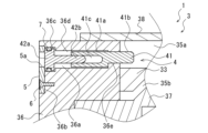
- FIG. 3 is a partially enlarged view showing a lock pin of the tool changer of FIG. 1;
- FIG. 4 is a partially enlarged view showing a state in which the lock pin of FIG. 3 has advanced into the cylinder chamber.
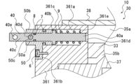
- 5 is a partially enlarged view showing a lock pin different from the lock pin of FIG. 3.
- FIG. FIG. 6 is a partially enlarged view showing a state in which the lock pin of FIG. 5 has advanced into the cylinder chamber.
- One aspect of the present invention is a tool changing device comprising a master plate having a cylinder chamber and a piston member reciprocating within the cylinder chamber, and a tool plate attached to and detached from the master plate by the reciprocation of the piston member.
- the master plate has a lock pin extending and retracting into the cylinder chamber for restricting the reciprocating motion of the piston member.
- the tool changer has a lock pin that can be retracted into and out of the cylinder chamber.
- the reciprocating motion of the piston member is restricted by the movement of the lock pin into the cylinder chamber. Since the piston member is restricted from moving to the side of separating from the tool plate, it is possible to prevent the tool plate from unintentionally separating from the master plate.
- the lock pin is not a member for connecting the master plate and the tool plate, but an independent member for restricting the movement of the piston member to the detachment side. Even if the operator erroneously gives an instruction to remove the tool plate, the removal of the tool plate can be suppressed.
- lock pin be retracted into and out of the cylinder chamber by manual operation. By doing so, it is possible to simplify the configuration of the tool changing device, improve operational stability, and reduce costs.
- the lock pin has a screw member and a piston lock member that is screwed into the screw member, and is configured such that the piston lock member moves into and out of the cylinder chamber by rotating the screw member. is preferred. By doing so, the lock pin can be easily operated.
- the piston member can be reciprocated by the supply of fluid, and that the lock pin advances into the cylinder chamber when the supply of the fluid is stopped.
- the tool plate is separated from the master plate.
- back pressure from an air-driven device such as an air cylinder used in other equipment is applied to the solenoid valve exhaust port side for the tool changer, and the piston member moves in the detachment direction.
- the tool plate may come off. Unintentional detachment of the tool plate can be suppressed by extending the lock pin into the cylinder chamber when not in operation.
- a tool changer 1 which is an embodiment of the present invention, mainly includes a tool plate 2 on which tools (not shown) are mounted, and a master plate 3 to which the tool plate 2 is detachable.
- the tool plate 2 is a substantially cylindrical member and has an insertion hole 21 formed in its center.
- the master plate 3 has a tubular portion 37 a that can be inserted into the insertion hole 21 .
- the tool plate 2 and the master plate 3 are detachable.
- the master plate 3 is mounted on, for example, a robot arm (not shown), and the tool plate 2 is mounted with tools. By attaching and detaching a plurality of tool plates 2 to which different tools are attached to the master plate 3, the robot arm can exchange various tools (tool plates 2).
- the master plate 3 includes a master master plate main body 32 having a cylinder chamber 35 formed therein, a piston member 33 mounted so as to be able to reciprocate in the cylinder chamber 35 , and a piston member 33 being moved by the reciprocating motion of the piston member 33 . and a locking member that moves in a direction substantially perpendicular to the direction of reciprocation.
- the master plate 3 also has a lock pin 4, which will be described later.
- a plurality of balls 34 are used as the locking member.
- the master plate main body 32 is formed with a flow passage (not shown) through which fluid flows in and out of the cylinder chamber 35 .
- the master plate main body 32 includes a first cylindrical body 36 formed with a through hole forming a side wall of the cylinder chamber 35, and a second cylindrical body 36 fixed to the lower side of the through hole of the first cylindrical body 36. a body 37; A portion of the second tubular body 37 constitutes a tubular portion 37a.
- the upper portion of the through hole of the first tubular body 36 is sealed with a lid portion 38 . That is, in this embodiment, the master plate main body 32 is composed of the first cylindrical body 36 and the second cylindrical body 37, and the cylinder chamber 35 is formed by and the upper surface of the second tubular body 37 .
- Both the first tubular body 36 and the second tubular body 37 are provided in a substantially cylindrical shape.
- the fluid is not particularly limited, for example, air is used.
- the flow path is formed in the first cylindrical body 36.
- the cylinder chamber 35 is divided into an upper cylinder chamber 35a and a lower cylinder chamber 35b by a piston member 33, which will be described later.
- the flow passage is composed of a first flow passage through which the fluid flows in and out of the upper cylinder chamber 35a, and a second flow passage through which the fluid flows into and out of the lower cylinder chamber 35b on the opposite side of the upper cylinder chamber 35a and the piston member 33. including.
- the first flow path and the second flow path are connected to a fluid supply device (not shown) in the factory via solenoid valves (not shown).
- the first flow path moves the piston member 33 toward the tool plate 2 by supplying fluid to the upper cylinder chamber 35a.
- the ball 34 moves toward the side where the tool plate 2 is connected to the master plate 3 (outside the tubular member 37a).
- the second flow passage discharges the fluid in the lower cylinder chamber 35b.
- the second flow path moves the piston member 33 toward the master plate 3 by supplying fluid to the lower cylinder chamber 35b.
- the balls 34 move toward the side where the tool plate 2 is separated from the master plate 3 (inside the cylindrical member 37 a ).
- the first flow passage discharges the fluid in the upper cylinder chamber 35a.
- a stepped portion to which the second cylindrical body 37 is attached is provided on the lower surface of the first cylindrical body 36 .
- the second cylindrical body 37 is fixed to this stepped portion.
- the second cylindrical body 37 has a collar portion 37b fitted to the stepped portion, and a cylindrical portion 37a projecting downward from the collar portion 37b. Therefore, the cylindrical portion 37a protrudes downward from the first cylindrical body 36.
- the second cylindrical body 37 is formed with an insertion hole through which the rod 33a of the piston member 33 is inserted.
- the master plate 3 and the tool plate 2 have contact surfaces 3a, 2a that contact each other in the connected state.
- the lower surface of the first tubular body 36 and the lower surface of the flange portion 37b are flush with each other and abut against the contact surface 2a of the tool plate 2 in the connected state. That is, in the present embodiment, the flush surface formed by the lower surface of the first tubular body 36 and the lower surface of the flange portion 37b of the second tubular body 37 serves as the contact surface 3a of the master plate 3. and the tool plate 2 are connected, the contact surfaces 3a and 2a are in close contact with each other.
- a plurality of holding holes 37c for holding the balls 34 are drilled in the tubular portion 37a in a direction perpendicular to the axis of the tubular portion 37a.
- the plurality of balls 34 are arranged at approximately equal intervals in the circumferential direction of the holding hole 37c.
- the holding hole 37c holds the ball 34 so as to be able to extend and retract from the side surface of the tubular portion 37a.
- the diameter of the holding hole 37c outside the cylindrical portion 37a is set smaller than the diameter of the ball 34 to prevent the ball 34 from falling out of the cylindrical portion 37a.
- the piston member 33 is provided so as to reciprocate in the axial direction of the cylindrical portion 37a, that is, in a direction substantially perpendicular to the contact surfaces 3a and 2a by the pressure of the fluid in the cylinder chamber 35. Due to the reciprocating motion of the piston member 33, the plurality of balls 34 protrude and retreat from the side surface of the cylindrical portion 37a.
- the piston member 33 includes a rod 33a inserted through the insertion hole of the second tubular portion 37a, and a cam portion fixed to the tip (lower end) of the rod 33a projecting from the tubular portion 37a. 33b. A side surface of the cam portion 33b abuts on the ball 34 and restricts the ball 34 from moving inside the cylindrical portion 37a.
- the cam portion 33b allows the ball 34 to move inward from the outer surface of the tubular portion 37a when the piston member 33 is positioned upward, while preventing the ball 34 from falling inside the tubular portion 37a. are preventing.
- a side surface of the cam portion 33b is formed with a sloped surface that slopes inward as it goes downward. A locked state with the locked portion 22 of the plate 2 is obtained.
- the cam portion 33b has two inclined surfaces with different inclination angles.
- the angle formed by the two inclined surfaces with respect to the axial direction of the cylindrical portion 37a is larger in the lower inclined surface in the figure and smaller in the following upper inclined surface.
- a substantially disc-shaped rod top surface 33c is formed on the top of the rod 33a of the piston member 33.
- the rod top surface 33c divides the cylinder chamber 35 into an upper cylinder chamber 35a and a lower cylinder chamber 35b.
- Tool plate An insertion hole 21 is formed in the tool plate 2 , and a locked portion 22 to which the ball 34 is locked is formed in the insertion hole 21 .
- the engaged portion 22 is a recess formed on the surface of the insertion hole 21, and this recess is formed continuously in the circumferential direction.
- the tubular portion 37a is inserted into the insertion hole 21, and the piston member 33 is moved downward.
- the ball 34 is pushed out of the cylindrical portion 37a by the cam portion 33b, and part of it enters the engaged portion 22. As shown in FIG.
- the locked portion 22 includes a side surface 22 a of the locked portion parallel to the axis of the insertion hole 21 and a side surface 22 a of the locked portion parallel to the axis of the insertion hole 21 . It has a locking portion bottom surface 22 b and a locked portion top surface 22 c that is inclined with respect to the axis of the insertion hole 21 . That is, the locked portion top surface 22c is formed so as to increase in diameter from the upper side to the lower side of the tool plate 2 . In other words, the locked portion top surface 22c is connected to the locked portion side surface 22a so that the diameter of the insertion hole 21 increases from the upper side toward the lower side.
- the master plate 3 is provided with a lock pin 4 that restricts the reciprocating motion of the piston member 33 by moving in and out of the cylinder chamber 35 .
- the lock pin 4 of this embodiment has a piston lock member 41 whose tip portion extends into the cylinder chamber 35 and a screw member 42 for retracting and extending the piston lock member 41 toward the inside of the cylinder chamber 35 .
- a lock pin hole 36 a for accommodating the lock pin 4 is bored in the first cylindrical body 36 of the master plate 3 so as to be perpendicular to the axis of the piston member 33 .
- the lock pin 4 is configured such that the piston lock member 41 moves into and out of the cylinder chamber 35 by rotating the screw member 42 within the lock pin hole 36a. Reciprocating motion of the piston member 33 within the cylinder chamber 35 is restricted by the forward end portion of the piston lock member 41 advancing into the cylinder chamber 35 .
- the piston lock 4 restricts the return movement of the piston member 33 (movement to the side away from the tool plate 2).
- the lock pin 4 engages a male screw formed in the screw portion 42b of the screw member 42 and a female screw hole 41c formed in the root portion 41a of the piston lock member 41, and engages the piston lock member 41. By rotating the screw member 42, the full length can be expanded and contracted.
- the third portion 36e movably accommodates the tip portion 41b of the piston lock member 41.
- the screw member 42 is rotated in one direction (eg, counterclockwise) with the tool.
- the tool is used to rotate the screw member 42 in the opposite direction (for example, clockwise).
- the distal end portion 41b has a substantially rectangular cross section
- the third portion 36e has a rectangular tubular shape. . Therefore, the reliability of extending and contracting the piston lock member 41 can be improved.
- the third portion 36e has a smaller cross-sectional area than the second portion 36d, it restricts the root portion 41a from moving toward the cylinder chamber 35 side. Therefore, it is possible to prevent the female screw hole 41c of the piston lock member 41 from slipping out of the screw portion 42b and the piston lock 4 from becoming unretractable.
- the master plate 30 of the tool changer 10 is provided with a lock pin 40 that restricts the reciprocating motion of the piston member 33 by advancing into the cylinder chamber 35 .
- a lock mechanism that prevents the tool plate 2 from unintentionally detaching from the master plate 30 in the tool changer 10 of this embodiment is composed of a lock pin 40 , an elastic member, and a lock shaft 8 .
- a coil spring 9 is used as the elastic member.
- a lock pin hole 361 a for accommodating the lock pin 40 is bored in the first tubular body 361 of the master plate 30 so as to be perpendicular to the axis of the piston member 33 .
- the tip portion 40 a of the lock pin 40 advances into the cylinder chamber 35 to restrict the reciprocating motion of the piston member 33 within the cylinder chamber 35 .
- Two insertion holes 40d and 40e through which the lock shaft 8 is inserted are formed in the rear end portion 40c.
- the two insertion holes 40 d and 40 e are formed in parallel in the axial direction of the lock pin 40 .
- the axial direction of the insertion holes 40 d and 40 e is perpendicular to the axial direction of the lock pin 40 .
- a lock pin hole 361a formed in the first cylindrical body 361 communicates between the outer peripheral side wall of the first cylindrical body 361 and the inner peripheral side wall of the first cylindrical body 361 (the side wall of the cylinder chamber 35).
- a plate concave portion 361 b is formed on the outer peripheral wall of the first cylindrical body 361 to fit the drop prevention plate 50 that prevents the lock pin 40 from dropping off from the master plate 3 .
- the fall prevention plate 50 is fixed to the plate concave portion 361b with the bolt 6. As shown in FIG.
- the fall prevention plate 50 is formed with a lock pin hole 50a through which the rear end portion 40c of the lock pin 40 is inserted.
- a portion of the drop-off prevention plate 50 is formed thick, and a lock pin hole 50a is formed in the thick portion 50b.
- the outer surface of the thick portion 50 b protrudes from the outer peripheral surface (outer surface) of the first cylindrical body 361 .
- the surface opposite to the outer peripheral surface of the thick portion 50b is positioned inside the lock pin hole 361a. That is, a portion of the thick portion 50b is formed in a cylindrical shape and fitted into the lock pin hole 361a.
- a seal member 7 such as an O-ring is provided at this fitting portion to prevent the fluid in the cylinder chamber 35 from leaking to the outside.
- the seal material 7 is also provided on the rear end portion 40c of the lock pin 40 that is inserted through the lock pin hole 50a.
- a shaft hole 50c through which the lock shaft 8 is inserted is formed in the thick portion 50b.
- the shaft hole 50c is formed such that its axial direction is orthogonal to the axial direction of the lock pin hole 50a.
- the diameter of the shaft hole 50c and the diameter of the insertion holes 40d and 40e of the lock pin 40 are substantially the same. Unintentional movement of the lock pin 40 is restricted by inserting the lock shaft 8 through the shaft hole 50c and the insertion holes 40d and 40e.
Landscapes
- Engineering & Computer Science (AREA)
- Robotics (AREA)
- Mechanical Engineering (AREA)
- Manipulator (AREA)
- Automatic Tool Replacement In Machine Tools (AREA)
Priority Applications (3)
| Application Number | Priority Date | Filing Date | Title |
|---|---|---|---|
| KR1020247004752A KR20240033016A (ko) | 2021-10-26 | 2022-08-26 | 툴교환장치 |
| CN202280053739.1A CN117751026A (zh) | 2021-10-26 | 2022-08-26 | 工具更换装置 |
| JP2022571229A JP7306589B1 (ja) | 2021-10-26 | 2022-08-26 | ツール交換装置 |
Applications Claiming Priority (2)
| Application Number | Priority Date | Filing Date | Title |
|---|---|---|---|
| JP2021174862 | 2021-10-26 | ||
| JP2021-174862 | 2021-10-26 |
Publications (1)
| Publication Number | Publication Date |
|---|---|
| WO2023074105A1 true WO2023074105A1 (ja) | 2023-05-04 |
Family
ID=86157723
Family Applications (1)
| Application Number | Title | Priority Date | Filing Date |
|---|---|---|---|
| PCT/JP2022/032196 Ceased WO2023074105A1 (ja) | 2021-10-26 | 2022-08-26 | ツール交換装置 |
Country Status (4)
| Country | Link |
|---|---|
| JP (1) | JP7306589B1 (https=) |
| KR (1) | KR20240033016A (https=) |
| CN (1) | CN117751026A (https=) |
| WO (1) | WO2023074105A1 (https=) |
Cited By (1)
| Publication number | Priority date | Publication date | Assignee | Title |
|---|---|---|---|---|
| WO2024252501A1 (ja) * | 2023-06-05 | 2024-12-12 | ビー・エル・オートテック株式会社 | マスタプレートおよびツール交換装置 |
Citations (5)
| Publication number | Priority date | Publication date | Assignee | Title |
|---|---|---|---|---|
| JPS60123288A (ja) * | 1983-12-07 | 1985-07-01 | 株式会社東芝 | 指交換可能な把持装置 |
| JPH0526283U (ja) * | 1991-09-23 | 1993-04-06 | 株式会社ハーモ | アタツチメント着脱装置 |
| JPH0729311U (ja) * | 1993-11-12 | 1995-06-02 | 株式会社コガネイ | 締結装置 |
| JP2009023050A (ja) * | 2007-07-20 | 2009-02-05 | Star Seiki Co Ltd | ロボットアームカップリング装置 |
| JP2020131305A (ja) * | 2019-02-13 | 2020-08-31 | 株式会社コスメック | 工具交換装置 |
Family Cites Families (5)
| Publication number | Priority date | Publication date | Assignee | Title |
|---|---|---|---|---|
| JP3212150B2 (ja) | 1992-08-07 | 2001-09-25 | 株式会社日立製作所 | 半導体装置 |
| TW200833959A (en) * | 2007-02-07 | 2008-08-16 | Wei-Yue Wu | An auxiliary locating device for the cylinder |
| WO2017212790A1 (ja) * | 2016-06-08 | 2017-12-14 | ビー・エル・オートテック株式会社 | ツール交換装置 |
| KR102751585B1 (ko) * | 2019-09-30 | 2025-01-10 | 삼성전자 주식회사 | 로봇 툴 체인저 |
| JP7159506B2 (ja) * | 2020-07-01 | 2022-10-24 | ビー・エル・オートテック株式会社 | ツール交換装置 |
-
2022
- 2022-08-26 KR KR1020247004752A patent/KR20240033016A/ko active Pending
- 2022-08-26 WO PCT/JP2022/032196 patent/WO2023074105A1/ja not_active Ceased
- 2022-08-26 JP JP2022571229A patent/JP7306589B1/ja active Active
- 2022-08-26 CN CN202280053739.1A patent/CN117751026A/zh active Pending
Patent Citations (5)
| Publication number | Priority date | Publication date | Assignee | Title |
|---|---|---|---|---|
| JPS60123288A (ja) * | 1983-12-07 | 1985-07-01 | 株式会社東芝 | 指交換可能な把持装置 |
| JPH0526283U (ja) * | 1991-09-23 | 1993-04-06 | 株式会社ハーモ | アタツチメント着脱装置 |
| JPH0729311U (ja) * | 1993-11-12 | 1995-06-02 | 株式会社コガネイ | 締結装置 |
| JP2009023050A (ja) * | 2007-07-20 | 2009-02-05 | Star Seiki Co Ltd | ロボットアームカップリング装置 |
| JP2020131305A (ja) * | 2019-02-13 | 2020-08-31 | 株式会社コスメック | 工具交換装置 |
Cited By (1)
| Publication number | Priority date | Publication date | Assignee | Title |
|---|---|---|---|---|
| WO2024252501A1 (ja) * | 2023-06-05 | 2024-12-12 | ビー・エル・オートテック株式会社 | マスタプレートおよびツール交換装置 |
Also Published As
| Publication number | Publication date |
|---|---|
| JP7306589B1 (ja) | 2023-07-11 |
| CN117751026A (zh) | 2024-03-22 |
| JPWO2023074105A1 (https=) | 2023-05-04 |
| KR20240033016A (ko) | 2024-03-12 |
Similar Documents
| Publication | Publication Date | Title |
|---|---|---|
| US5083352A (en) | Tool changing device for robot | |
| JPS601948Y2 (ja) | 工具ホルダのクランプ装置 | |
| JP7306589B1 (ja) | ツール交換装置 | |
| US12134157B2 (en) | Clamping apparatus | |
| JPS59175984A (ja) | 工業用ロボツトのハンド交換装置 | |
| JP7127836B2 (ja) | 工具交換装置 | |
| CN101983114A (zh) | 速换柄轴、孔刀及其方法 | |
| JP2022179629A (ja) | ツール交換装置 | |
| CN110253628A (zh) | 一种机器人末端工具快换装置 | |
| JP2018118333A (ja) | 自動工具交換装置 | |
| KR20190008902A (ko) | 툴 교환 장치 | |
| JP2002301630A (ja) | 工作機械の工作物固定用治具 | |
| KR20230107138A (ko) | 엔드 이펙터 교환 장치 | |
| WO2017212791A1 (ja) | ツール交換装置 | |
| JP2012240175A (ja) | チャック装置のストッパ取付構造 | |
| US8667660B2 (en) | Quick change clamping device | |
| JP5901938B2 (ja) | ロボットハンドおよびロボットハンドシステム | |
| JPS6212522Y2 (https=) | ||
| US4722536A (en) | Quick change chuck jaw | |
| JP4040806B2 (ja) | 締結部材の分解工具及び分解方法 | |
| JP3292926B2 (ja) | 工具保持装置 | |
| TWI914578B (zh) | 末端執行器交換裝置 | |
| CN215542126U (zh) | 一种旋转式双头外牙接头组件 | |
| JP2012166330A (ja) | 搬送装置のチャック装置 | |
| WO2024247204A1 (ja) | マスタプレート、ツール交換装置および保持部材 |
Legal Events
| Date | Code | Title | Description |
|---|---|---|---|
| WWE | Wipo information: entry into national phase |
Ref document number: 2022571229 Country of ref document: JP |
|
| 121 | Ep: the epo has been informed by wipo that ep was designated in this application |
Ref document number: 22886439 Country of ref document: EP Kind code of ref document: A1 |
|
| WWE | Wipo information: entry into national phase |
Ref document number: 202280053739.1 Country of ref document: CN |
|
| ENP | Entry into the national phase |
Ref document number: 20247004752 Country of ref document: KR Kind code of ref document: A |
|
| WWE | Wipo information: entry into national phase |
Ref document number: 1020247004752 Country of ref document: KR |
|
| NENP | Non-entry into the national phase |
Ref country code: DE |
|
| 122 | Ep: pct application non-entry in european phase |
Ref document number: 22886439 Country of ref document: EP Kind code of ref document: A1 |