WO2023067672A1 - 室内機、および空気調和機 - Google Patents
室内機、および空気調和機 Download PDFInfo
- Publication number
- WO2023067672A1 WO2023067672A1 PCT/JP2021/038516 JP2021038516W WO2023067672A1 WO 2023067672 A1 WO2023067672 A1 WO 2023067672A1 JP 2021038516 W JP2021038516 W JP 2021038516W WO 2023067672 A1 WO2023067672 A1 WO 2023067672A1
- Authority
- WO
- WIPO (PCT)
- Prior art keywords
- housing
- filter
- indoor unit
- heat exchanger
- outer shell
- Prior art date
- Legal status (The legal status is an assumption and is not a legal conclusion. Google has not performed a legal analysis and makes no representation as to the accuracy of the status listed.)
- Ceased
Links
Images






Classifications
-
- F—MECHANICAL ENGINEERING; LIGHTING; HEATING; WEAPONS; BLASTING
- F24—HEATING; RANGES; VENTILATING
- F24F—AIR-CONDITIONING; AIR-HUMIDIFICATION; VENTILATION; USE OF AIR CURRENTS FOR SCREENING
- F24F1/00—Room units for air-conditioning, e.g. separate or self-contained units or units receiving primary air from a central station
- F24F1/0007—Indoor units, e.g. fan coil units
- F24F1/0071—Indoor units, e.g. fan coil units with means for purifying supplied air
- F24F1/0073—Indoor units, e.g. fan coil units with means for purifying supplied air characterised by the mounting or arrangement of filters
-
- F—MECHANICAL ENGINEERING; LIGHTING; HEATING; WEAPONS; BLASTING
- F24—HEATING; RANGES; VENTILATING
- F24F—AIR-CONDITIONING; AIR-HUMIDIFICATION; VENTILATION; USE OF AIR CURRENTS FOR SCREENING
- F24F1/00—Room units for air-conditioning, e.g. separate or self-contained units or units receiving primary air from a central station
- F24F1/0007—Indoor units, e.g. fan coil units
- F24F1/0043—Indoor units, e.g. fan coil units characterised by mounting arrangements
- F24F1/0057—Indoor units, e.g. fan coil units characterised by mounting arrangements mounted in or on a wall
-
- F—MECHANICAL ENGINEERING; LIGHTING; HEATING; WEAPONS; BLASTING
- F24—HEATING; RANGES; VENTILATING
- F24F—AIR-CONDITIONING; AIR-HUMIDIFICATION; VENTILATION; USE OF AIR CURRENTS FOR SCREENING
- F24F13/00—Details common to, or for air-conditioning, air-humidification, ventilation or use of air currents for screening
- F24F13/20—Casings or covers
-
- F—MECHANICAL ENGINEERING; LIGHTING; HEATING; WEAPONS; BLASTING
- F24—HEATING; RANGES; VENTILATING
- F24F—AIR-CONDITIONING; AIR-HUMIDIFICATION; VENTILATION; USE OF AIR CURRENTS FOR SCREENING
- F24F13/00—Details common to, or for air-conditioning, air-humidification, ventilation or use of air currents for screening
- F24F13/28—Arrangement or mounting of filters
Definitions
- the present disclosure relates to indoor units and air conditioners.
- Patent Document 1 a wall-mounted indoor unit that is provided with a filter and fixed to a wall surface is known.
- the front panel is provided so that it can be freely opened and closed, and it was necessary to open the front panel in order to perform filter maintenance work such as cleaning. Therefore, there is a problem that the man-hours and time required for the filter maintenance work increase.
- an object of the present disclosure is to provide an indoor unit having a structure capable of reducing the man-hours and time required for filter maintenance work, and an air conditioner equipped with such an indoor unit.
- One aspect of the indoor unit according to the present disclosure is an indoor unit of an air conditioner, and is a wall-mounted indoor unit fixed to a wall surface, and has a heat exchanger, a blower, and a suction port.
- a housing for housing the heat exchanger and the blower therein; and a filter disposed between the suction port and the heat exchanger, wherein the housing includes an insertion port for inserting the filter.
- the insertion port opens forward, and the filter is detachably attached to the housing from the outside of the housing via the insertion port.
- One aspect of the air conditioner according to the present disclosure includes the above indoor unit and outdoor unit.
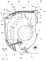
- FIG. 3 is a sectional view showing the indoor unit in the embodiment, taken along the line III-III in FIG. 2; 4 is an exploded perspective view showing an outer shell member and a filter in the embodiment; FIG. It is a perspective view which shows a part of outer shell member in embodiment.
- FIG. 4 is a perspective view showing a portion of the outer shell member and the filter when being inserted into the insertion port in the embodiment;
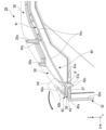
- FIG. 4 is a cross-sectional view showing part of the indoor unit in the embodiment, showing the first projecting portion.
- FIG. 2 is a cross-sectional view showing an example of a conventional indoor unit; It is sectional drawing which shows a part of procedure which attaches the filter to a housing
- the drawings show the X-axis, Y-axis, and Z-axis as appropriate.
- the X-axis indicates one of the horizontal directions.
- the Y-axis indicates the other horizontal direction.
- the Z-axis indicates the vertical direction.
- the horizontal direction along the X-axis is called “front-rear direction X”
- the horizontal direction along the Y-axis is called “left-right direction Y”
- the vertical direction is called “vertical direction Z”.
- the front-rear direction X, the left-right direction Y, and the vertical direction Z are directions orthogonal to each other.
- the side of the vertical direction Z to which the Z-axis arrow points (+Z side) is defined as the upper side
- the opposite side of the vertical direction Z to which the Z-axis arrow points (-Z side) is defined as the lower side.
- the side of the front-rear direction X to which the arrow of the X-axis points (+X side) is defined as the front side
- the side opposite to the side of the front-rear direction X to which the arrow of the X-axis is directed (-X side) is defined as the rear side.
- the left-right direction Y is the left-right direction when the indoor units of the following embodiments are viewed from the front (+X direction).
- the side of the horizontal direction Y to which the Y-axis arrow points (+Y side) is the right side
- the opposite side of the horizontal direction Y to the direction of the Y-axis arrow (-Y side) is the left side.
- FIG. 1 is a schematic diagram showing a schematic configuration of an air conditioner 100 according to the present embodiment.
- the air conditioner 100 includes an outdoor unit 10, an indoor unit 20, and a circulation path section 18.
- the outdoor unit 10 is arranged outdoors.
- the indoor unit 20 is arranged indoors.
- the outdoor unit 10 and the indoor unit 20 are connected to each other by a circulation path portion 18 through which the refrigerant 19 circulates.
- the air conditioner 100 can adjust the temperature of the indoor air by exchanging heat between the refrigerant 19 flowing through the circulation path section 18 and the indoor air in which the indoor unit 20 is arranged.
- the refrigerant 19 for example, a fluorine-based refrigerant having a low global warming potential (GWP), a hydrocarbon-based refrigerant, or the like can be used.
- GWP global warming potential
- the outdoor unit 10 includes a housing 11, a compressor 12, a heat exchanger 13, a flow control valve 14, a blower 15, a four-way valve 16, and a controller 17.
- a compressor 12 , a heat exchanger 13 , a flow control valve 14 , a blower 15 , a four-way valve 16 , and a controller 17 are accommodated inside the housing 11 .
- the compressor 12 , the heat exchanger 13 , the flow control valve 14 and the four-way valve 16 are provided in a portion of the circulation path section 18 located inside the housing 11 .
- Compressor 12 , heat exchanger 13 , flow control valve 14 , and four-way valve 16 are connected by a portion of circulation path portion 18 located inside housing 11 .
- the four-way valve 16 is provided in a portion of the circulation path portion 18 that is connected to the discharge side of the compressor 12 .
- the four-way valve 16 can reverse the direction of the refrigerant 19 flowing through the circulation path portion 18 by switching a part of the circulation path portion 18 .
- the path connected by the four-way valve 16 is the path indicated by the solid line in the four-way valve 16 in FIG. 1
- the refrigerant 19 flows through the circulation path portion 18 in the direction indicated by the solid arrow in FIG.
- the path connected by the four-way valve 16 is the path indicated by the dashed line in the four-way valve 16 in FIG. 1
- the refrigerant 19 flows in the circulation path section 18 in the direction indicated by the dashed arrow in FIG.
- the indoor unit 20 includes a housing 21, a heat exchanger 22, a blower 23, and a controller 24.
- the housing 21 accommodates the heat exchanger 22, the blower 23, and the controller 24 inside.
- the indoor unit 20 is capable of a cooling operation for cooling the air in the room in which the indoor unit 20 is arranged and a heating operation for warming the air in the room in which the indoor unit 20 is arranged.
- the refrigerant 19 flowing through the circulation path portion 18 flows in the direction indicated by the solid arrow in FIG. That is, when the indoor unit 20 is in a cooling operation, the refrigerant 19 flowing through the circulation path portion 18 flows through the compressor 12, the heat exchanger 13 of the outdoor unit 10, the flow control valve 14, and the heat exchanger 22 of the indoor unit 20. in that order back to the compressor 12 .
- the heat exchanger 13 inside the outdoor unit 10 functions as a condenser
- the heat exchanger 22 inside the indoor unit 20 functions as an evaporator.
- the refrigerant 19 flowing through the circulation path portion 18 flows in the direction indicated by the dashed line in FIG.
- the refrigerant 19 flowing through the circulation path portion 18 flows through the compressor 12, the heat exchanger 22 of the indoor unit 20, the flow control valve 14, and the heat exchanger 13 of the outdoor unit 10. in that order back to the compressor 12 .
- the heat exchanger 13 inside the outdoor unit 10 functions as an evaporator
- the heat exchanger 22 inside the indoor unit 20 functions as a condenser.
- FIG. 2 is a perspective view showing the indoor unit 20.
- FIG. FIG. 3 is a cross-sectional view showing the indoor unit 20, taken along line III--III in FIG.
- the indoor unit 20 is a wall-mounted indoor unit that is fixed to an indoor wall surface WS.
- the indoor unit 20 has a substantially rectangular parallelepiped shape elongated in the horizontal direction Y. As shown in FIG.
- the blower 23 housed inside the housing 21 of the indoor unit 20 is a cross-flow fan. Although not shown, the blower 23 extends in the horizontal direction Y. As shown in FIG. The blower 23 rotates around a rotation axis R extending in the horizontal direction Y. As shown in FIG. 3, the blower 23 housed inside the housing 21 of the indoor unit 20 is a cross-flow fan. Although not shown, the blower 23 extends in the horizontal direction Y. As shown in FIG. The blower 23 rotates around a rotation axis R extending in the horizontal direction Y. As shown in FIG.
- the heat exchanger 22 has a first heat exchanger 22a, a second heat exchanger 22b, and a third heat exchanger 22c.
- the first heat exchanger 22 a is positioned in front of the blower 23 .
- the first heat exchanger 22a extends in the vertical direction Z when viewed in the left-right direction Y.
- the second heat exchanger 22 b and the third heat exchanger 22 c are positioned above the blower 23 .
- the second heat exchanger 22b extends upward and obliquely rearward from the upper end of the first heat exchanger 22a when viewed in the left-right direction Y.
- the third heat exchanger 22c is positioned behind the second heat exchanger 22b.
- the third heat exchanger 22c extends downward and obliquely rearward from the upper end of the second heat exchanger 22b when viewed in the left-right direction Y.
- the housing 21 of the indoor unit 20 has an outer shell member 30 and an air passage member 21a.
- the outer shell member 30 is a member forming part of the outer shell of the housing 21 .
- the outer shell member 30 is a design panel that improves the appearance design of the indoor unit 20 .
- the outer shell member 30 has a substantially rectangular parallelepiped box shape that opens rearward. As shown in FIG. 3, the rear opening of the outer shell member 30 is closed by the air passage member 21a.
- the air passage member 21a is a member that constitutes a part of the air passage through which the air sucked into the housing 21 by the blower 23 passes.
- an air passage through which air sucked into housing 21 by blower 23 is formed by air passage member 21 a and outer shell member 30 .
- the air passage member 21a is hooked on a mounting plate (not shown) fixed to the wall surface WS. Thereby, the indoor unit 20 is fixed to the wall surface WS.
- the outer shell member 30 is integrally molded. In other words, the outer shell member 30 in this embodiment does not have a separable portion.
- FIG. 4 is an exploded perspective view showing the outer shell member 30 and a filter 40 which will be described later. As shown in FIG. 4, the outer shell member 30 has an upper wall portion 31, a front wall portion 32, a pair of side wall portions 33a and 33b, and a lower wall portion . Each wall portion constituting outer shell member 30 in the present embodiment is plate-shaped.
- the upper wall portion 31 is a wall portion positioned upward among the walls constituting the housing 21 .
- the upper wall portion 31 extends in the left-right direction Y.
- the upper wall portion 31 constitutes substantially the entire upper outer shell of the outer shell of the housing 21 .
- the upper outer shell of the outer shell of the housing 21 is composed of the upper wall portion 31 and the upper end portion of the air passage member 21a.
- the upper end portion of the air passage member 21 a constitutes substantially the entire rear edge portion of the upper outer shell of the housing 21 .
- the upper wall portion 31 has an upper wall body portion 31a and an upper wall inclined portion 31b.
- the upper wall body portion 31 a is a rear portion of the upper wall portion 31 .
- the upper surface of the upper wall body portion 31a is substantially orthogonal to the vertical direction Z.
- the upper wall inclined portion 31 b is a front portion of the upper wall portion 31 .
- the upper wall inclined portion 31b protrudes forward and obliquely downward from the front end portion of the upper wall body portion 31a. That is, the upper wall inclined portion 31b is positioned downward toward the front.
- the upper surface of the upper wall inclined portion 31b faces upward and obliquely forward.
- the dimension in the front-rear direction X of the upper wall inclined portion 31b is smaller than the dimension in the front-rear direction X of the upper wall body portion 31a.
- a connection portion between the upper surface of the upper wall body portion 31a and the upper surface of the upper wall inclined portion 31b is rounded. Since the upper wall portion 31 has the upper wall inclined portion 31b, the front end portion of the upper end portion of the housing 21 has a shape in which the corner portions of a rectangular parallelepiped are chamfered.
- the front wall portion 32 is a wall portion that constitutes the outer shell on the front side of the outer shell of the housing 21 . As shown in FIG. 3 , the front wall portion 32 is positioned in front of the heat exchanger 22 . More specifically, the front wall portion 32 is positioned in front of the first heat exchanger 22a and the second heat exchanger 22b. The upper end of the front wall portion 32 is connected to the front end of the upper wall portion 31 .
- the front wall portion 32 has a front wall body portion 32a and a front wall inclined portion 32b.
- the front wall body portion 32 a is a portion including the upper portion of the front wall portion 32 .
- the upper end portion of the front wall body portion 32a is connected to the front end portion of the upper wall inclined portion 31b.
- the front wall body portion 32a is positioned in front of the first heat exchanger 22a and the second heat exchanger 22b.
- the front surface of the front wall body portion 32a is substantially perpendicular to the front-rear direction X. As shown in FIG. More specifically, the front surface of the front wall body portion 32a is located slightly rearward as it goes downward.
- the front wall inclined portion 32b is part of the lower portion of the front wall portion 32.
- the dimension in the vertical direction Z of the front wall inclined portion 32b is smaller than the dimension in the vertical direction Z of the front wall body portion 32a.
- the front wall inclined portion 32b protrudes downward and obliquely rearward from the lower end portion of the front wall body portion 32a. That is, the front wall inclined portion 32b is located rearward as it goes downward.
- the front surface of the front wall inclined portion 32b faces forward and obliquely downward. Since the front wall portion 32 has the front wall inclined portion 32b, the front end portion of the lower end portion of the housing 21 has a shape in which the corner portions of a rectangular parallelepiped are chamfered.
- the pair of side wall portions 33a and 33b constitute outer shells on both sides in the left-right direction Y of the outer shell of the housing 21, respectively.
- the side wall portion 33 a constitutes a right (+Y side) outer shell of the outer shell of the housing 21 .
- the side wall portion 33b constitutes the outer shell on the left side ( ⁇ Y side) of the outer shell of the housing 21.
- the right surface of the side wall portion 33a and the left surface of the side wall portion 33b are orthogonal to the horizontal direction Y.
- the pair of side wall portions 33a and 33b protrude rearward from both ends of the front wall portion 32 in the left-right direction Y, respectively.
- the side wall portion 33 a protrudes rearward from the right end portion of the front wall portion 32 .
- the side wall portion 33b protrudes rearward from the left end portion of the front wall portion 32 .
- the upper end portion of the side wall portion 33 a is connected to the right end portion of the upper wall portion 31 .
- An upper end portion of the side wall portion 33 b is connected to a left end portion of the upper wall portion 31 .
- the lower wall portion 34 constitutes the lower outer shell of the outer shell of the housing 21 .
- the lower wall portion 34 protrudes rearward from the lower end portion of the front wall portion 32 . More specifically, the lower wall portion 34 protrudes rearward from the lower end portion of the front wall inclined portion 32b.
- the lower surface of the lower wall portion 34 is substantially perpendicular to the vertical direction Z.
- the lower surface of the lower wall portion 34 is positioned slightly downward toward the rear.
- the connecting portion between the front end portion of the lower surface of the lower wall portion 34 and the lower end portion of the front surface of the front wall inclined portion 32b is rounded.
- the housing 21 has an inlet 20a and an outlet 20b.
- the suction port 20a and the blowout port 20b are formed in the outer shell member 30.
- the suction port 20 a is formed in the upper wall portion 31 .
- the outlet 20b is formed in the front wall inclined portion 32b of the front wall portion 32. As shown in FIG.
- the suction port 20a opens upward.
- a plurality of suction ports 20a are provided.
- the plurality of suction ports 20a are arranged in a matrix in the front-rear direction X and the left-right direction Y. As shown in FIG. That is, a plurality of rows in which a plurality of suction ports 20a are arranged in the left-right direction Y are provided side by side in the front-rear direction X. As shown in FIG. In the present embodiment, three rows in which six suction ports 20a are arranged in the left-right direction Y are provided side by side in the front-rear direction X. As shown in FIG. The suction port 20a in the rearmost row among the three rows is formed in the upper wall body portion 31a.
- the suction port 20a in the row located in the center in the front-rear direction X among the three rows is formed across the upper wall body portion 31a and the upper wall inclined portion 31b.
- the suction port 20a in the frontmost row among the three rows is formed in the upper wall inclined portion 31b.
- the air outlet 20b opens forward and downward.
- the outlet 20b extends in the left-right direction Y.
- the dimension of the outlet 20b in the left-right direction Y is larger than half the dimension of the housing 21 in the left-right direction Y.
- the air sucked into the housing 21 by the blower 23 is blown out into the room from the outlet 20b.
- the blower outlet 20b is provided with a wind direction adjusting unit 25 capable of opening and closing the blower outlet 20b. The direction of the air blown into the room from the outlet 20b is adjusted by the wind direction adjusting unit 25 .
- the housing 21 has an insertion opening 50 into which a filter 40, which will be described later, is inserted.
- the insertion port 50 opens forward.
- the insertion port 50 is exposed in front of the indoor unit 20.
- insertion port 50 is formed in the upper portion of housing 21 . More specifically, the insertion opening 50 is formed in the upper wall inclined portion 31 b of the upper wall portion 31 of the outer shell member 30 .
- the insertion port 50 opens forward and upward.
- the insertion port 50 is arranged side by side in front of the plurality of suction ports 20a arranged in a matrix.
- the insertion opening 50 extends in the left-right direction Y.
- the insertion opening 50 has a substantially rectangular shape elongated in the horizontal direction Y when viewed from the front.
- a later-described filter 40 can be inserted into the insertion port 50 from the outside of the housing 21 .
- the dimension of the insertion port 50 in the left-right direction Y is larger than the dimension of the filter 40 in the left-right direction Y.
- the dimension of the insertion port 50 in the left-right direction Y is substantially the same as the dimension of the filter 40 in the left-right direction Y.
- the dimension in the vertical direction Z of the insertion port 50 is larger than the dimension in the vertical direction Z of the filter 40 .
- two insertion openings 50 are provided side by side in the horizontal direction Y. As shown in FIG.
- the plurality of suction ports 20a and the two insertion ports 50 are configured such that the through hole 31c formed in the upper wall portion 31 is partitioned by the plurality of first beam portions 31d and the plurality of second beam portions 31e. formed by The through hole 31c penetrates the upper wall portion 31 in the vertical direction Z.
- the through hole 31c is a substantially rectangular hole elongated in the horizontal direction Y when viewed from above.
- the center of the through hole 31c in the left-right direction Y is positioned to the left (-Y direction) of the center of the upper wall portion 31 in the left-right direction Y.
- the dimension of the through hole 31 c in the left-right direction Y is larger than half the dimension of the housing 21 in the left-right direction Y. As shown in FIG.
- the dimension in the horizontal direction Y of the through hole 31c is the same as the dimension in the horizontal direction Y of the outlet 20b.
- the front edge of the through-hole 31 c is positioned at the front edge of the upper wall portion 31 .
- the front edge of the through hole 31 c constitutes the front edges of the two insertion openings 50 .
- the rear edge of the through-hole 31 c is positioned at the rear edge of the upper wall portion 31 .
- the plurality of first beam portions 31d extend in the horizontal direction Y.
- the plurality of first beam portions 31d are arranged at intervals in the front-rear direction X. As shown in FIG. Three first beam portions 31d are provided. Both ends of the plurality of first beam portions 31d in the left-right direction Y are connected to portions located on both sides in the left-right direction Y of the inner edge of the through hole 31c.
- the plurality of second beam portions 31e extend in the front-rear direction X when viewed from above.
- the plurality of second beam portions 31e are arranged at intervals in the left-right direction Y. As shown in FIG. Five second beam portions 31e are provided.
- Each second beam 31e connects the plurality of first beams 31d.
- the rear end portions of the plurality of second beam portions 31e are connected to the rearward portion of the inner edge of the through hole 31c.
- the second beam portion 31e positioned at the center in the horizontal direction Y among the plurality of second beam portions 31e is the central beam portion 31f.
- a front end portion of the central beam portion 31f is connected to a portion located on the front side of the inner edge of the through hole 31c.
- the two insertion openings 50 are partitioned in the left-right direction Y by the center beam portion 31f.
- the front end portions of the second beam portions 31e other than the central beam portion 31f are connected to the first beam portion 31d positioned most forward among the plurality of first beam portions 31d.
- the central beam portion 31f protrudes downward more than the other second beam portions 31e.
- a portion of the through-hole 31c located on the right side (+Y direction) of the central beam portion 31f is referred to as a right through-hole 31g.
- a portion of the through hole 31c located to the left (-Y direction) of the central beam portion 31f is called a left through hole 31h.
- FIG. 5 is a perspective view showing part of the outer shell member 30.
- FIG. FIG. 6 is a perspective view showing a portion of the outer shell member 30 and the filter 40 when being inserted into the insertion opening 50.
- FIG. FIG. 7 is a cross-sectional view showing part of the indoor unit 20, showing a first projecting portion 42c, which will be described later.
- FIG. 8 is a cross-sectional view showing part of the indoor unit 20, showing a second projecting portion 36, which will be described later.
- the housing 21 has a placement portion 37 provided on the front edge of the insertion port 50 .
- the mounting portion 37 protrudes rearward from the front edge of the insertion opening 50 .
- the mounting portion 37 extends in the left-right direction Y.
- the mounting portion 37 has a substantially rectangular plate shape elongated in the left-right direction Y.
- a plate surface of the mounting portion 37 is orthogonal to the vertical direction Z.
- the mounting portion 37 extends from the right end to the left end of the through hole 31c.
- a front end portion of the central beam portion 31 f is connected to the mounting portion 37 .
- the mounting portion 37 has a concave portion 37a recessed forward from the rear edge portion of the mounting portion 37.
- a plurality of recesses 37a are provided at intervals in the left-right direction Y.
- Six recesses 37a are provided in the present embodiment. Of the six recesses 37a, three recesses 37a are formed in a portion of the mounting portion 37 located to the right (+Y direction) of the central beam portion 31f. The remaining three recesses 37a out of the six recesses 37a are formed in a portion of the mounting portion 37 positioned to the left (-Y direction) of the central beam portion 31f.
- a first protrusion 42c which will be described later, passes through the interior of the recess 37a in the vertical direction Z from above.
- the housing 21 has a pair of guide portions 35a and 35b.
- the pair of guide portions 35a and 35b are provided at portions located on both sides in the left-right direction Y of the inner edge of the right through hole 31g.
- the guide portion 35a is provided at an edge located on the left side (-Y side) of the inner edge of the right through hole 31g.
- the left edge portion of the inner edge of the right through hole 31g is the right (+Y side) edge portion of the central beam portion 31f.
- the guide portion 35b is provided at an edge located on the right side of the inner edge of the right through hole 31g.
- the pair of guide portions 35a and 35b protrude in the left-right direction Y from the respective edges of the right through hole 31g so as to approach each other.
- the guide portion 35a and the guide portion 35b are arranged symmetrically in the horizontal direction Y. As shown in FIG. Therefore, in the following description, one guide portion 35a will be described as a representative of the pair of guide portions 35a and 35b, and description of the other guide portion 35b may be omitted.
- the guide portion 35a extends in the front-rear direction X when viewed from above.
- a front end portion of the guide portion 35 a is connected to the mounting portion 37 .
- the rear end portion of the guide portion 35a is connected to the rear edge portion of the inner edge of the right through hole 31g.
- the guide portion 35a has a guide wall portion 35e and an opposing wall portion 35f.
- the guide wall portion 35e has an elongated plate shape extending in the front-rear direction X. As shown in FIG.
- the plate surface of the guide wall portion 35e faces the vertical direction Z.
- the guide wall portion 35e is arranged below and away from the first beam portion 31d.
- the opposing wall portion 35f protrudes upward from the rear end portion of the guide wall portion 35e.
- the upper end portion of the opposing wall portion 35f is connected to the rear edge portion of the inner edge of the right through hole 31g.
- the front surface of the opposing wall portion 35f is a surface orthogonal to the front-rear direction X. As shown in FIG.
- the housing 21 has a pair of guide portions 35c and 35d.
- the pair of guide portions 35c and 35d are the same as the pair of guide portions 35a and 35b except that they are provided for the left through hole 31h.
- the housing 21 has a second protruding portion 36 that protrudes upward from the placement portion 37 .
- the second protruding portions 36 are provided in portions of the mounting portion 37 positioned in front of the guide portions 35a, 35b, 35c, and 35d. That is, four second protrusions 36 are provided in the present embodiment. Two of the four second protrusions 36 are located on the right side (+Y direction) of the central beam portion 31 f of the mounting portion 37 . The remaining two second protrusions 36 out of the four second protrusions 36 are located on the left side (-Y direction) of the central beam portion 31f of the mounting portion 37 .
- the second projecting portion 36 has a substantially triangular shape when viewed in the horizontal direction Y.
- the second protruding portion 36 has a substantially quadrangular pyramid shape protruding upward.
- the housing 21 has support projections 38 that protrude upward from the mounting portion 37 .
- the support projection 38 protrudes upward from the front end portion of the mounting portion 37 .
- the support projection 38 has a substantially triangular shape when viewed in the horizontal direction Y.
- the upper end of the support protrusion 38 is located below the upper end of the second protrusion 36 .
- the support protrusion 38 is positioned in front of the second protrusion 36 .
- the support protrusion 38 extends in the left-right direction Y.
- the support protrusion 38 extends from the right end to the left end of the mounting portion 37 .
- the indoor unit 20 includes a filter 40 arranged between the suction port 20a and the heat exchanger 22.
- the filter 40 is positioned between the suction port 20a and the heat exchanger 22 in the vertical direction Z.
- the air sucked into the housing 21 from the suction port 20 a flows through the filter 40 and then to the heat exchanger 22 .
- Filter 40 can trap at least some of the dust contained in the air passing through filter 40 . Therefore, by passing the air through the filter 40 , at least part of the dust contained in the air can be removed from the air passing through the filter 40 .
- two filters 40 are provided side by side in the horizontal direction Y in the present embodiment.
- the two filters 40 can be inserted into the two insertion openings 50 from outside the housing 21 .
- Each filter 40 is inserted into each insertion port 50 and inserted into the housing 21 .
- One of the two filters 40 is arranged in the right through hole 31g.
- the other of the two filters 40 is arranged in the left through hole 31h.
- Each filter 40 is detachably attached to the housing 21 from the outside of the housing 21 via each insertion port 50 .
- the size of each filter 40 in the left-right direction Y is smaller than the size of each insertion opening 50 in the left-right direction Y.
- the two filters 40 have the same configuration as each other. In the following description, the filter 40 located on the right side (+Y direction) will be described as a representative of the two filters 40 .
- FIG. 9 is a perspective view showing the filter 40.
- the filter 40 is a substantially rectangular plate-shaped member.
- the plate surface of the filter 40 faces the vertical direction Z.
- the filter 40 has a filter body portion 41 and a handle portion 42 .
- the filter main body 41 has a substantially rectangular plate shape.
- the filter body portion 41 is a portion arranged between the suction port 20 a and the heat exchanger 22 .
- the filter main body 41 has a grid portion 41d and a trapping portion 41c.
- the grid portion 41d is made of resin, for example.
- the lattice portion 41d and the handle portion 42 are integrally formed.
- the lattice portion 41d is a portion formed in a lattice shape by four beam portions 41e extending in the left-right direction Y and four beam portions 41f extending in the front-rear direction X. As shown in FIG.
- the trapping portion 41c is a net-like portion through which air can pass. At least part of the dust contained in the air passing through the trapping portion 41c is trapped by the trapping portion 41c by the air passing through the trapping portion 41c.
- the trapping portion 41c is provided in each hole in the grid-shaped grid portion 41d. Each hole in the grid portion 41d is surrounded by beam portions 41e adjacent in the front-rear direction X and beam portions 41f adjacent in the left-right direction Y, respectively. In the present embodiment, three rows in which three trapping portions 41c are arranged in the left-right direction Y are provided side by side in the front-rear direction X. As shown in FIG. In other words, each filter 40 is provided with nine trapping portions 41c.
- the nine trapping portions 41c of the filter 40 located on the right side (+Y direction) of the two filters 40 are arranged below the nine suction ports 20a formed by partitioning the right through hole 31g.
- the nine trapping portions 41c of the filter 40 located on the left side ( ⁇ Y direction) of the two filters 40 are respectively arranged below the nine suction ports 20a formed by partitioning the left through hole 31h. .
- the filter main body 41 has a first portion 41a and a second portion 41b.
- the first portion 41 a is the rear portion of the filter body portion 41 .
- the first portion 41a extends along a plane orthogonal to the vertical direction Z (XY plane).
- the second portion 41b extends forward and obliquely downward from the front end of the first portion 41a. As shown in FIG. 3, the first portion 41a is positioned below the upper wall body portion 31a.
- the second portion 41b is positioned below the upper wall inclined portion 31b.
- a front portion of the second portion 41 b is positioned below the insertion opening 50 .
- Both ends of the filter body 41 in the left-right direction Y are supported from below by the guide walls 35e of the pair of guides 35a and 35b. Both ends of the filter main body 41 in the left-right direction Y are positioned between the guide walls 35e of the pair of guides 35a and 35b and the first beam 31d. Both ends of the rear end portion of the filter main body 41 in the left-right direction Y are in contact with the front surfaces of the opposed wall portions 35f of the pair of guide portions 35a and 35b.
- the handle portion 42 is provided at the front end portion of the filter body portion 41 . More specifically, the handle portion 42 is provided at the front end portion of the second portion 41 b of the filter body portion 41 .
- the handle portion 42 is made of resin, for example.
- the handle portion 42 extends in the left-right direction Y. As shown in FIG. The handle portion 42 extends from the right end to the left end of the filter body portion 41 . As shown in FIG. 7 , the handle portion 42 is positioned in front of the insertion opening 50 .
- the handle portion 42 is mounted on the upper surface of the mounting portion 37 .
- the handle portion 42 is exposed to the outside of the housing 21 .
- the handle portion 42 has a base portion 42a, a cover wall portion 42b, and a first projecting portion 42c.
- the base portion 42a is mounted on the mounting portion 37.
- the base portion 42a has a substantially rectangular plate shape elongated in the horizontal direction Y.
- the plate surface of the base portion 42a is perpendicular to the vertical direction Z.
- the rearmost edge of the base portion 42a is connected to the frontmost beam portion 41e among the plurality of beam portions 41e forming the lattice portion 41d.
- a hole portion 42d is formed in the lower surface of the base portion 42a.
- the hole portions 42d are formed at both end portions in the left-right direction Y on the lower surface of the base portion 42a.
- the shape of the internal space of the hole portion 42d is a substantially quadrangular pyramid shape that protrudes upward.
- the second protrusion 36 is inserted from below into the hole 42d.
- a rear portion of the inner surface of the hole 42 d is in contact with the rear surface of the second projecting portion 36 .
- the inner surface of the hole portion 42d is hooked on the second projecting portion 36 from the rear (-X direction).
- the dimension in the vertical direction Z of the hole portion 42 d is larger than the dimension in the vertical direction Z of the second projecting portion 36 .
- a front portion of the inner surface of the hole portion 42d faces the front surface of the second projecting portion 36 with a gap therebetween.
- the cover wall portion 42b protrudes upward from the base portion 42a. More specifically, the cover wall portion 42b protrudes upward and obliquely rearward from the front end portion of the base portion 42a. That is, the cover wall portion 42b is located rearward as it goes upward.
- the dimension of the cover wall portion 42b in the direction in which the cover wall portion 42b protrudes from the base portion 42a is larger than the dimension of the base portion 42a in the front-rear direction X.
- the position in the front-rear direction X of the upper end portion of the cover wall portion 42b is a position slightly behind the position in the front-rear direction X of the rear end portion of the base portion 42a.
- the cover wall portion 42b extends in the left-right direction Y.
- the cover wall portion 42b extends from the right end to the left end of the base portion 42a.
- the cover wall portion 42b has a substantially rectangular plate shape elongated in the horizontal direction Y.
- At least a portion of the cover wall portion 42b overlaps the insertion opening 50 when viewed from the front.
- the entire cover wall portion 42b overlaps the insertion opening 50 when viewed from the front.
- the front surface of the cover wall portion 42b is the design surface 42e.
- the design surface 42e is a flat surface.
- the design surface 42e faces forward and obliquely upward.
- the surface roughness of the design surface 42 e is smaller than the surface roughness of the other surfaces of the handle portion 42 .
- the design surface 42e is a glossy surface.
- the design surface 42 e is exposed to the outside of the housing 21 .
- the inclination angle ⁇ of the cover wall portion 42b with respect to the base portion 42a is, for example, about 45°.
- the inclination angle ⁇ of the cover wall portion 42b with respect to the base portion 42a is the angle between the lower surface of the base portion 42a and the design surface 42e of the cover wall portion 42b.
- the inclination angle ⁇ is substantially the same as the angle at which the upper wall inclined portion 31b is inclined with respect to the horizontal plane (XY plane) perpendicular to the vertical direction Z. As shown in FIG.
- the first protrusion 42c protrudes downward from the base 42a.
- the first protruding portion 42c protrudes downward from the rear end portion of the base portion 42a.
- the upper end portion of the first projecting portion 42 c is connected to the rear end portion of the base portion 42 a and the front end portion of the filter body portion 41 .
- the upper end portion of the first projecting portion 42c is connected to the lower surface of the frontmost beam portion 41e among the plurality of beam portions 41e of the filter body portion 41 .
- the first projecting portion 42c is inserted from above into a recessed portion 37a formed in the mounting portion 37 .
- the first protruding portion 42c protrudes below the mounting portion 37 through the interior of the recessed portion 37a.
- the first projecting portion 42c is hooked from the rear on a portion of the inner edge of the recess 37a located on the front side. As a result, the first projecting portion 42c is hooked on the mounting portion 37 from behind.
- a plurality of first protrusions 42c are provided at intervals in the left-right direction Y. As shown in FIG. More specifically, three first protrusions 42 c are provided for each filter 40 . Each first projecting portion 42c passes through each recess 37a from above.
- the lower end portion of the front end portion of the handle portion 42 is a supported end portion 43 that is hooked on the support projection 38 from the rear (-X direction).
- the supported end portion 43 is a corner portion where the front end portion of the base portion 42a and the lower end portion of the cover wall portion 42b are connected.
- the handle portion 42 protrudes upward from the support projection 38 .
- the upper surface of the base portion 42a is located above the upper end portions of the support projections 38.
- an air cleaning filter 60 is attached to the filter 40 .
- the air purifying filter 60 is a filter capable of inactivating at least part of bacteria, fungi, viruses, etc. contained in the air passing through the air purifying filter 60 .
- the air purifying filter 60 is attached to the lower surface of the rear portion of the second portion 41 b of the filter body portion 41 .
- the air cleaning filter 60 is positioned above the second heat exchanger 22b.
- the air cleaning filter 60 extends from the right end of the filter 40 to the left end. In the present embodiment, the air that has been sucked into the housing 21 from the suction port 20 a and has passed through the filter 40 passes through the air cleaning filter 60 .
- the dashed arrow indicates the air flow AF.
- FIG. 10 is a cross-sectional view showing part of the procedure for attaching the filter 40 to the housing 21.
- an operator who attaches the filter 40 to the housing 21 inserts the filter 40 with the air cleaning filter 60 attached into the insertion opening 50 from the front of the housing 21 .
- both ends in the horizontal direction Y of the portion of the filter 40 inserted into the housing 21 through the insertion port 50 are supported from below by a pair of guide portions 35a and 35b.
- the operator inserts the filter 40 into the housing 21 through the insertion opening 50 until the rear end of the filter main body 41 hits the front surface of the opposing wall 35f.
- the operator places the handle portion 42 on the placement portion 37 while the filter main body portion 41 abuts against the opposing wall portion 35f.
- the handle portion 42 is placed on the placing portion 37, the first projecting portion 42c of the handle portion 42 is inserted into the concave portion 37a formed in the placing portion 37, and the hole portion 42d of the handle portion 42 is inserted.
- the second projecting portion 36 formed on the mounting portion 37 is inserted therein.
- the lower end portion of the front end portion of the handle portion 42 that is, the supported end portion 43 is hooked on the support projection 38 from behind.
- the operator who removes the filter 40 from the housing 21 can remove the handle portion 42 placed on the mounting portion 37 from the front of the housing 21 without performing work such as removing a part of the housing 21, for example.
- the filter 40 can be removed from the housing 21 by moving the filter 40 by grasping with fingers. More specifically, the operator hooks the finger HF on the cover wall portion 42b of the handle portion 42 as indicated by the two-dot chain line in FIG. The operator pulls the cover wall portion 42b forward with fingers HF. At this time, the supported end portion 43 is hooked on the support projection 38, so that the handle portion 42 rotates in the direction of moving forward with the supported end portion 43 as a fulcrum when viewed in the left-right direction Y. As shown in FIG.
- the base portion 42a and the first projection portion 42c move upward, the first projection portion 42c is removed from the recess portion 37a, and the hole portion 42d formed in the base portion 42a moves upward from the second projection portion 36. do.
- the engagement between the first projecting portion 42c and the recessed portion 37a and the engagement between the second projecting portion 36 and the hole portion 42d are released.
- the operator lifts the handle portion 42 slightly upward to move the supported end portion 43 above the support protrusion 38 .
- the operator can pull the filter 40 out of the housing 21 and remove the filter 40 from the housing 21 .
- FIG. 11 is a cross-sectional view showing an indoor unit 120, which is an example of a conventional indoor unit.
- FIG. 12 is a cross-sectional view showing part of the procedure for attaching the filter 140 in the indoor unit 120 to the housing 121. As shown in FIG. In the description of the configuration of the indoor unit 120 below, the description may be omitted by assigning the same reference numerals to FIGS.
- the outer shell member 130 of the housing 121 includes a main body member 130a, a front panel 130b separate from the main body member 130a, have
- the front panel 130 b is a member that constitutes a part of the outer shell on the front side of the outer shell of the housing 121 .
- the main body member 130a is a part of the outer shell of the housing 121 that constitutes the part other than the front panel 130b.
- Outer shell member 130 has substantially the same configuration as outer shell member 30 of the present embodiment, except that it is composed of two members, body member 130a and front panel 130b.
- the front panel 130b constitutes more than half of the outer shell of the housing 121 on the front side.
- the front panel 130b is attached to the body member 130a so as to be openable and closable.
- the front panel 130b is attached to the body member 130a so as to be rotatable about an axis extending in the left-right direction Y with the upper end of the front panel 130b as a fulcrum.
- the front panel 130b is rotated, the front panel 130b is in an open state as shown in FIG.
- the front panel 130b is open, the gap in the vertical direction Z between the heat exchanger 22 and the upper wall of the walls forming the main body member 130a is exposed to the outside of the housing 121 .
- a plurality of suction ports 20a are formed in an upper wall portion of the wall portions that constitute the main body member 130a.
- the filter 140 in the indoor unit 120 covers the heat exchanger 22 from the front and above. More specifically, the filter main body 141 of the filter 140 includes a portion that covers the first heat exchanger 22a and the second heat exchanger 22b from the front inside the housing 121, and a second heat exchanger inside the housing 121. and a portion covering the vessel 22b and the third heat exchanger 22c from above.
- the filter 140 is attached to the housing 121 by engaging the lower end of the portion of the filter main body 141 located in front of the heat exchanger 22 with the housing 121 .
- An air cleaning filter 60 is attached to the rear surface of the lower end portion of the portion of the filter main body 141 positioned in front of the heat exchanger 22 .
- a handle portion 142 of the filter 140 is provided in a portion of the filter body portion 141 located in front of the heat exchanger 22 .
- the handle portion 142 is located above the lower end portion of the portion of the filter body portion 141 located in front of the heat exchanger 22 .
- the handle portion 142 protrudes forward.
- the handle portion 142 is covered from the front by the front panel 130b. Therefore, the handle portion 142 is not exposed to the outside of the housing 121 when the front panel 130b is closed.
- a worker who attaches the filter 140 to the housing 121 in the indoor unit 120 first opens the front panel 130b as shown in FIG. As described above, in this state, the gap in the vertical direction Z between the heat exchanger 22 and the upper wall of the walls forming the main body member 130 a is exposed to the outside of the housing 121 .
- the operator grips the handle portion 142 to insert the filter 140 into the exposed gap, bends the filter body portion 141 as shown in FIG. 11, and attaches the filter 140 to the housing 121. .
- the operator closes the front panel 130b.
- An operator who removes the filter 140 from the housing 121 opens the front panel 130b and then grabs the handle portion 142 exposed to the outside of the housing 121 to remove the filter 140 .
- the housing 21 has the insertion opening 50 into which the filter 40 is inserted.
- the insertion port 50 opens forward.
- the filter 40 is detachably attached to the housing 21 from the outside of the housing 21 via the insertion port 50 . Therefore, the filter 40 can be attached/detached to/from the housing 21 as described above without partially opening the housing 21 .
- the front panel 130b does not need to be opened and closed, so the man-hours and time required for the maintenance work of the filter 40 can be reduced.
- the front panel 130b does not need to be openable, so the main body member 130a and the front panel 130b of the conventional indoor unit 120 can be integrated.
- the outer shell member 30 can be made into the integrally molded member like this Embodiment. Therefore, the number of parts of the indoor unit 20 can be reduced compared to the case where the outer shell member 30 is made by combining a plurality of members. Therefore, the manufacturing cost of the indoor unit 20 can be reduced.
- the outer shell member 30 as an integrally molded member, a dividing line between different members does not appear on the outer surface of the outer shell member 30 . Therefore, the design of the exterior of the indoor unit 20 can be improved.
- the upper wall portion 31 of the housing 21 is formed with the suction port 20a that opens upward.
- the insertion port 50 is formed in the upper portion of the housing 21 . Therefore, by inserting the filter 40 into the housing 21 through the insertion port 50 , the filter 40 can be easily arranged below the suction port 20 a and above the heat exchanger 22 . As a result, even if a part of the filter 40 is not arranged in front of the heat exchanger 22 as in the conventional indoor unit 120, the entire suction port 20a can be easily covered from below with the filter 40, and the air is sucked from the suction port 20a. It is easy to pass all of the air through the filter 40.
- the upper wall portion 31 of the housing 21 has an upper wall inclined portion 31b positioned downward toward the front.
- the insertion port 50 is formed in the upper wall inclined portion 31b and opens forward and upward. Since the insertion opening 50 is formed in the upper wall inclined portion 31b in this way, the inside of the housing 21 is larger than that in the case where the insertion opening 50 is formed in a wall portion extending along the vertical direction Z, for example. Visibility from the outside of the housing 21 through 50 can be suppressed. Therefore, the filter main body 41 inserted into the housing 21 through the insertion port 50 can be made less visible to the user from the outside of the housing 21 . Thereby, the designability of the appearance of the indoor unit 20 can be further improved.
- the filter 40 includes the filter main body portion 41 arranged between the suction port 20a and the heat exchanger 22, and the handle portion 42 provided at the front end portion of the filter main body portion 41.
- the handle portion 42 is positioned in front of the insertion port 50 . Therefore, the insertion port 50 can be preferably covered from the front by the handle portion 42 . Accordingly, it is possible to further prevent the inside of the housing 21 from being seen from the outside of the housing 21 through the insertion port 50 . Therefore, the exterior design of the indoor unit 20 can be further improved.
- the filter 40 is removed from the housing 21, the operator can easily grasp the handle portion 42. As shown in FIG. Therefore, the work of removing the filter 40 from the housing 21 can be facilitated.
- the handle portion 42 has the cover wall portion 42b that at least partially overlaps the insertion port 50 when viewed from the front.
- the cover wall portion 42b is located rearward as it goes upward. Therefore, the cover wall portion 42b can easily be shaped along the upper wall inclined portion 31b, and the insertion opening 50 formed in the upper wall inclined portion 31b can be more preferably covered from the front by the cover wall portion 42b.
- the line of sight LS of the user can be easily blocked by the cover wall portion 42b, and the inside of the housing 21 can be more preferably viewed from the outside of the housing 21 through the insertion opening 50. can be suppressed. Therefore, the exterior design of the indoor unit 20 can be more suitably improved.
- the dimension of the cover wall portion 42b in the direction in which the cover wall portion 42b protrudes from the base portion 42a is large enough to block the line of sight LS of the user by the cover wall portion 42b and prevent the user from viewing the insertion port 50 from the outside. It is said.
- the dimension of the cover wall portion 42b is, for example, the position of the indoor unit 20 in the vertical direction Z in the room, or the average horizontal distance between the user and the indoor unit 20 when the user visually recognizes the indoor unit 20. , and the average height of the user.
- the size of the cover wall portion 42b is preferably as small as possible within a range in which the user's line of sight LS is suitably blocked by the cover wall portion 42b and the insertion port 50 is not visually recognized by the user from the outside.
- the design property of the portion of the handle portion 42 visible to the user can be improved.
- the designability of the appearance of the indoor unit 20 can be further improved.
- the surface roughness of the design surface 42e is made smaller than the surface roughness of the surfaces other than the design surface 42e in the handle portion 42, and the design surface 42e is glossy. The design of 42e is improved.
- the design surface 42e may be a surface whose design property is improved in any way as long as the design property is higher than that of the portion other than the design surface 42e of the handle portion 42.
- the design surface 42e may be a painted surface or a plated surface.
- the design of the design surface 42e of the handle 42 may be improved by making the handle 42 as a separate member from the filter main body 41 and changing the color of the resin forming the handle 42, for example.
- the housing 21 has the placement portion 37 provided at the front edge of the insertion port 50 .
- the handle portion 42 has a base portion 42a placed on the mounting portion 37, and a first projecting portion 42c that protrudes downward from the base portion 42a and is hooked on the mounting portion 37 from behind. Therefore, it is possible to suppress forward movement of the filter 40 with respect to the housing 21 by the first projecting portion 42 c being caught by the mounting portion 37 . This can prevent the filter 40 from unintentionally coming off the housing 21 .
- the first projecting portion 42c is inserted into the recess 37a formed in the mounting portion 37, and the first projecting portion 42c is hooked on the inner edge of the recess 37a. Therefore, the first projecting portion 42c can be stably hooked to the placing portion 37. As shown in FIG.
- the housing 21 has the second projecting portion 36 projecting upward from the placing portion 37 .
- a hole portion 42d into which the second projecting portion 36 is inserted is formed in the lower surface of the base portion 42a of the handle portion 42 . Therefore, the filter 40 can be further prevented from moving forward with respect to the housing 21 by the second projecting portion 36 being caught on the inner surface of the hole portion 42d. Accordingly, it is possible to further prevent the filter 40 from unintentionally coming off the housing 21 .
- the housing 21 has the support projection 38 with which the supported end portion 43, which is the lower end portion of the front end portion of the handle portion 42, is hooked from behind. Therefore, forward movement of the filter 40 with respect to the housing 21 can be further suppressed. Accordingly, it is possible to further prevent the filter 40 from unintentionally coming off the housing 21 . Further, as described above, when the filter 40 is removed from the housing 21, if the handle portion 42 is grasped with the fingers HF and pulled forward, the handle portion 42 extends in the horizontal direction Y with the supported end portion 43 as a fulcrum. Easy to turn around.
- the base portion 42a and the first projecting portion 42c can be easily lifted upward to facilitate the engagement between the first projecting portion 42c and the mounting portion 37 and the engagement between the second projecting portion 36 and the hole portion 42d. Easy to remove. Therefore, the filter 40 can be easily removed from the housing 21 .
- the indoor unit 20 is arranged at a relatively high position on the wall surface WS of the room, when removing the filter 40 from the housing 21, the operator extends his arm upward and pulls the handle 42 with his finger HF. to pull the filter 40 forward. As a result, even if the operator intends to simply pull the handle portion 42 forward, the handle portion 42 is likely to be pulled forward and downward. Therefore, an operator who removes the filter 40 from the housing 21 tends to unintentionally turn the handle portion 42 around the supported end portion 43 as a fulcrum. Therefore, it is easier to remove the filter 40 from the housing 21 .
- part of the air sucked into the housing 21 by the blower 23 passes through the insertion port 50 .
- the insertion port 50 can also be used as a suction port for sucking air into the housing 21 . Therefore, air can be easily sucked into the housing 21 .
- the size of the cover wall portion 42b is set to the minimum size within the range where the line of sight LS of the user can be blocked, air can be more easily sucked into the housing 21 through the insertion opening 50 .
- the outer shell member 30 includes a front wall portion 32 that is positioned in front of the heat exchanger 22 and constitutes a front outer shell of the outer shell of the housing 21, and a front wall portion a pair of side wall portions 33a and 33b projecting rearward from both ends in the left-right direction Y of the housing 21 and constituting outer shells on both sides in the left-right direction Y of the outer shell of the housing 21, and integrally formed therewith. molded. Therefore, when the indoor unit 20 is viewed from the front and when the indoor unit 20 is viewed from both the left-right direction Y, the design of the indoor unit 20 can be improved favorably.
- the front wall portion 32 of the outer shell member 30 can be formed integrally with the pair of side wall portions 33a and 33b in this manner because it is not necessary to open a part of the front wall portion 32 as a separate member as described above. It's for.
- the outer shell member 30 also has a lower wall portion 34 that constitutes the lower outer shell of the outer shells of the housing 21 . Therefore, the design of the indoor unit 20 when viewed from below can also be favorably improved.
- the filter 140 has a portion that covers the heat exchanger 22 from the front as in the conventional indoor unit 120
- the lower end of the portion that covers the heat exchanger 22 from the front of the filter 140 is attached to the housing 121. It is necessary to prevent the air sucked into the housing 121 from the suction port 20 a from flowing into the heat exchanger 22 through the gap between the filter 140 and the housing 121 .
- the handle portion 142 is provided at the lower end portion of the portion of the filter 140 that covers the heat exchanger 22 from the front, the case 121 is in the way, making it difficult to grasp the handle portion 142 .
- the handle portion 142 is arranged at a position above the lower end portion of the portion of the filter 140 that covers the heat exchanger 22 from the front, as described above.
- the filter 40 does not have a portion that covers the heat exchanger 22 from the front. Therefore, the front end portion of the filter 40 may be attached to the housing 21 in front of the insertion port 50 . That is, the filter 40 can cover the suction port 20a from below without disposing the front end portion of the filter 40 inside the housing 21 .
- the front end of the filter main body 41 is provided with a handle 42 having an easy-to-grip shape and the handle 42 is attached to the housing 21, the flow of the air after being sucked into the housing 21 is prevented by the handle 42. 42 does not interfere.
- the position and shape of the handle portion 42 can be set to a position and shape suitable for gripping the filter 40 while facilitating the flow of air inside the housing 21 . Therefore, the work of attaching and detaching the filter 40 to and from the housing 21 can be performed more easily.
- the insertion opening of the housing of the indoor unit may be formed at any position on the housing as long as it opens forward and allows the filter to be inserted from the outside of the housing of the indoor unit.
- the insertion opening may be formed in the central portion of the housing in the vertical direction Z, or may be formed in the lower portion of the housing. Only one insertion opening may be formed, or three or more insertion openings may be formed. A plurality of filters may be inserted into one insertion port.
- the shape and type of the filter placed between the suction port and the heat exchanger are not particularly limited.
- the filter inserted into the housing through the insertion opening has a portion that covers the heat exchanger from the front.
- the handle of the filter may be arranged at any position on the filter and may have any shape.
- the cover wall portion of the handle portion of the filter may only partially overlap the insertion opening when viewed from the front.
- the shape of the housing of the indoor unit is not particularly limited.
- the upper wall portion of the housing may not have the upper wall inclined portion.
- the outer shell member may have any configuration as long as it constitutes a part of the outer shell of the housing.
- the outer shell member does not have to be integrally molded. That is, the outer shell member may be configured by combining a plurality of members.
- the outer shell member may have an outer shell member main body and a decorative part attached to the outer shell member main body.
Landscapes
- Engineering & Computer Science (AREA)
- Chemical & Material Sciences (AREA)
- Combustion & Propulsion (AREA)
- Mechanical Engineering (AREA)
- General Engineering & Computer Science (AREA)
- Air Filters, Heat-Exchange Apparatuses, And Housings Of Air-Conditioning Units (AREA)
Priority Applications (5)
| Application Number | Priority Date | Filing Date | Title |
|---|---|---|---|
| CN202180100588.6A CN118043596A (zh) | 2021-10-19 | 2021-10-19 | 室内机以及空调机 |
| DE112021008375.9T DE112021008375T5 (de) | 2021-10-19 | 2021-10-19 | Innenraumeinheit und Klimaanlage |
| PCT/JP2021/038516 WO2023067672A1 (ja) | 2021-10-19 | 2021-10-19 | 室内機、および空気調和機 |
| US18/571,596 US20240280291A1 (en) | 2021-10-19 | 2021-10-19 | Indoor unit and air conditioner |
| JP2023553924A JP7462851B2 (ja) | 2021-10-19 | 2021-10-19 | 室内機、および空気調和機 |
Applications Claiming Priority (1)
| Application Number | Priority Date | Filing Date | Title |
|---|---|---|---|
| PCT/JP2021/038516 WO2023067672A1 (ja) | 2021-10-19 | 2021-10-19 | 室内機、および空気調和機 |
Publications (1)
| Publication Number | Publication Date |
|---|---|
| WO2023067672A1 true WO2023067672A1 (ja) | 2023-04-27 |
Family
ID=86058902
Family Applications (1)
| Application Number | Title | Priority Date | Filing Date |
|---|---|---|---|
| PCT/JP2021/038516 Ceased WO2023067672A1 (ja) | 2021-10-19 | 2021-10-19 | 室内機、および空気調和機 |
Country Status (5)
| Country | Link |
|---|---|
| US (1) | US20240280291A1 (https=) |
| JP (1) | JP7462851B2 (https=) |
| CN (1) | CN118043596A (https=) |
| DE (1) | DE112021008375T5 (https=) |
| WO (1) | WO2023067672A1 (https=) |
Citations (5)
| Publication number | Priority date | Publication date | Assignee | Title |
|---|---|---|---|---|
| JPS60121127U (ja) * | 1984-01-26 | 1985-08-15 | 三菱重工業株式会社 | 空気調和機用エアフイルタ |
| JPH04132322U (ja) * | 1991-05-23 | 1992-12-08 | ダイキン工業株式会社 | 空気調和機 |
| JP2001324211A (ja) * | 2000-05-19 | 2001-11-22 | Fujitsu General Ltd | 空気調和機 |
| JP2016205675A (ja) * | 2015-04-20 | 2016-12-08 | ジョンソンコントロールズ ヒタチ エア コンディショニング テクノロジー(ホンコン)リミテッド | 空気調和機の室内機 |
| CN212057519U (zh) * | 2020-03-30 | 2020-12-01 | 广州松下空调器有限公司 | 一种空调器过滤网的固定结构以及空调器 |
Family Cites Families (13)
| Publication number | Priority date | Publication date | Assignee | Title |
|---|---|---|---|---|
| JPH03236525A (ja) * | 1990-02-14 | 1991-10-22 | Toshiba Corp | 空気清浄機能付き空気調和機 |
| JP3642064B2 (ja) * | 2003-09-01 | 2005-04-27 | ダイキン工業株式会社 | 空気調和機の室内機およびその製造方法 |
| WO2006011704A2 (en) * | 2004-07-27 | 2006-02-02 | Lg Electronics Inc. | Air conditioner |
| KR101123316B1 (ko) * | 2004-08-16 | 2012-03-20 | 엘지전자 주식회사 | 공기조화기 |
| JP4490475B2 (ja) * | 2007-12-25 | 2010-06-23 | 三菱電機株式会社 | 空気調和機の室内ユニット |
| JP4713658B2 (ja) | 2009-09-09 | 2011-06-29 | シャープ株式会社 | 空気調和機 |
| JP5805305B2 (ja) * | 2012-04-06 | 2015-11-04 | 三菱電機株式会社 | 床置き型空気調和機 |
| EP3159633B1 (en) * | 2014-06-19 | 2019-08-28 | Mitsubishi Electric Corporation | Indoor unit for air-conditioning device, and air-conditioning device provided with said indoor unit |
| WO2016151641A1 (ja) * | 2015-03-26 | 2016-09-29 | 三菱電機株式会社 | 空気調和機の室内機 |
| KR102393890B1 (ko) * | 2016-07-22 | 2022-05-03 | 엘지전자 주식회사 | 공기조화기 |
| US11118791B2 (en) * | 2017-03-03 | 2021-09-14 | Mitsubishi Electric Corporation | Indoor unit of air-conditioning apparatus |
| KR102664218B1 (ko) * | 2019-08-30 | 2024-05-09 | 삼성전자주식회사 | 공기조화기 |
| CA3120136A1 (en) * | 2020-05-14 | 2021-11-14 | Man-D-Tec, Inc. | Elevator system ventilation |
-
2021
- 2021-10-19 US US18/571,596 patent/US20240280291A1/en active Pending
- 2021-10-19 WO PCT/JP2021/038516 patent/WO2023067672A1/ja not_active Ceased
- 2021-10-19 CN CN202180100588.6A patent/CN118043596A/zh active Pending
- 2021-10-19 JP JP2023553924A patent/JP7462851B2/ja active Active
- 2021-10-19 DE DE112021008375.9T patent/DE112021008375T5/de active Pending
Patent Citations (5)
| Publication number | Priority date | Publication date | Assignee | Title |
|---|---|---|---|---|
| JPS60121127U (ja) * | 1984-01-26 | 1985-08-15 | 三菱重工業株式会社 | 空気調和機用エアフイルタ |
| JPH04132322U (ja) * | 1991-05-23 | 1992-12-08 | ダイキン工業株式会社 | 空気調和機 |
| JP2001324211A (ja) * | 2000-05-19 | 2001-11-22 | Fujitsu General Ltd | 空気調和機 |
| JP2016205675A (ja) * | 2015-04-20 | 2016-12-08 | ジョンソンコントロールズ ヒタチ エア コンディショニング テクノロジー(ホンコン)リミテッド | 空気調和機の室内機 |
| CN212057519U (zh) * | 2020-03-30 | 2020-12-01 | 广州松下空调器有限公司 | 一种空调器过滤网的固定结构以及空调器 |
Also Published As
| Publication number | Publication date |
|---|---|
| CN118043596A (zh) | 2024-05-14 |
| JP7462851B2 (ja) | 2024-04-05 |
| JPWO2023067672A1 (https=) | 2023-04-27 |
| US20240280291A1 (en) | 2024-08-22 |
| DE112021008375T5 (de) | 2024-08-01 |
Similar Documents
| Publication | Publication Date | Title |
|---|---|---|
| CN112752928B (zh) | 空调 | |
| JP6157884B2 (ja) | 一体型空気調和機 | |
| JP6020543B2 (ja) | 空気調和装置の室内機 | |
| WO2016157293A1 (ja) | 空気調和機の室内機 | |
| WO2016157292A1 (ja) | 空気調和機の室内機 | |
| WO2016157295A1 (ja) | 空気調和機の室内機 | |
| JP5029544B2 (ja) | 熱交換器固定板及び空気調和機 | |
| WO2023067672A1 (ja) | 室内機、および空気調和機 | |
| JP2002061877A (ja) | 空気調和機 | |
| JP5956163B2 (ja) | 空気調和機 | |
| JP3855465B2 (ja) | 空気調和機 | |
| JP2002333159A (ja) | 空気調和機 | |
| KR20070060501A (ko) | 공기조화기 | |
| JP5505321B2 (ja) | 空気調和機 | |
| JP5780986B2 (ja) | 空気調和機の室内機及びこの室内機を備えた空気調和機 | |
| WO2022168820A1 (ja) | 冷却ユニット及び空調機 | |
| JP2008133969A (ja) | 空気調和機 | |
| JP3432790B2 (ja) | 空気調和機 | |
| JP2005351555A (ja) | 空気調和機 | |
| JP2005214470A (ja) | 換気ユニット | |
| JP7507075B2 (ja) | 空気調和装置 | |
| TR2024001503T2 (tr) | İç mekan ünitesi ve klima. | |
| JP3656397B2 (ja) | 空調換気扇 | |
| JP7179173B2 (ja) | 空気調和機の室内機、及び室内機の付加装置 | |
| JP2023178729A (ja) | 冷却貯蔵庫 |
Legal Events
| Date | Code | Title | Description |
|---|---|---|---|
| 121 | Ep: the epo has been informed by wipo that ep was designated in this application |
Ref document number: 21961325 Country of ref document: EP Kind code of ref document: A1 |
|
| WWE | Wipo information: entry into national phase |
Ref document number: 2023553924 Country of ref document: JP |
|
| WWE | Wipo information: entry into national phase |
Ref document number: 18571596 Country of ref document: US |
|
| WWE | Wipo information: entry into national phase |
Ref document number: 202180100588.6 Country of ref document: CN |
|
| WWE | Wipo information: entry into national phase |
Ref document number: 2024/001503 Country of ref document: TR |
|
| WWE | Wipo information: entry into national phase |
Ref document number: 202427009626 Country of ref document: IN Ref document number: 2401000902 Country of ref document: TH |
|
| WWE | Wipo information: entry into national phase |
Ref document number: 112021008375 Country of ref document: DE |
|
| 122 | Ep: pct application non-entry in european phase |
Ref document number: 21961325 Country of ref document: EP Kind code of ref document: A1 |